brain · opening and closing this mechatronic system should be able ... controlled servomotor...
TRANSCRIPT

1/36
ROBOTIC
OVER - UNDER GUN
SELF OPENING – SELF CLOSING
AN INNOVATIVE CONCEPT
OF
Ballistic RAdical INnovations
BRAIN
A MECHATRONIC MECHANISM
CONCEPTUAL STUDY

2/36
Executive Summary
This technical description reports on the conceptual design of a mechatronic
mechanism for actuated barrel opening of a generic hunting gun, which requires
almost no effort from a user. This system can be easily developed and manufactured
with no substantial modifications of the production line, as the design is generic
enough and does not affect existing designs and mechanisms.
The initial requirements of the design are clarified. An analysis of the main concept
follows, including a variation from the basic one. The design is illustrated by CAD
figures for better comprehension. To examine the feasibility of the design, a set of
experimental measurements on a generic gun system were taken. These measurements
were used to select the main system subcomponents such as actuators and batteries.
The results suggest possible motor assemblies (including peripherals and power
source). The appendix includes a detailed analysis of each part of the mechatronic
mechanism.
Summarizing, this technical study focuses on the automation of a generic hunting gun,
minimizing the required modifications from the current state. In fact, the mechanism
fits well within the actual shape of a generic gun. An appropriate controlled
mechatronic mechanism is proposed. Efforts have been made so that the system
retains backward compatibility in terms of users’ habits. An innovative concept has
been derived during this process, which can form the basis for future designs.

3/36
1. GENERAL REQUIREMENTS
Typically, any user of a conventional gun must use the Top Lever to open the Barrel.
By default this mechanism is not ambidextrous and requires effort by the user.
To automate the barrel opening, a novel mechatronic design is required. During
opening and closing this mechatronic system should be able to override mistaken
orders – such as double or continuous pressing of button - until the opening or the
closing is completed (or an obstacle has been found).
The technical requirements for this design include:
- Opening time duration at Normal holding position : less than 1 sec (includes
Action Bolt Unlocking and Barrel Opening)
- Opening time duration at Horizontal holding position (capability test) : less
than 1.2 sec (includes Action Bolt Unlocking and Barrel Opening)
- Closing time : less than 1.5 sec.
- Barrel opening angle (normal) : 45o.
- Minimum automatic openings on the same battery without recharging : 2000.
- External modifications are allowed but in a minor degree.
- The system should be ambidextrous.
- Additional weight to be kept minimal.
- Robustness against vibrations of recoil.
The programmatic requirements include:
- Development of a system capable of integration in a generic gun without
imposing serious modifications to the initial system, and without affecting its
firing capabilities , able to operate manually whenever needed.
- Cost to be kept to a minimum.
2. MECHATRONIC DESIGN DESCRIPTION
General
The main idea of the developed mechatronic design is that a microprocessor-
controlled servomotor pushes the barrel to open or close through a novel transmission
mechanism. The servomotor, the driving electronics and the batteries are located in
the stock, and the motion reaches the barrel through a mainly translational
mechanism. Two variations, called Variation I and II, have been developed, which
share the same basic components. The two variations differ in the way the main motor
is decoupled from the transmission. These will be discussed later. Inherently, the
system has the capability to act in various modes, i.e. the barrel may open in (a)
Automatic mode, (b) Semi-automatic mode and (c) Manual mode. It may also close in
Automatic mode or in Manual mode .The user selects the desired mode by a switch.
Although the mechanism needs electrical power (in the non-manual modes), it is

4/36
designed so that it can operate manually in the case of a failure of the mechatronic
system, despite the non-backdriveability of the transmission. The mechanism has a
fail-safe design, so that it can be used manually even if the switch is not in the manual
position, in case of emergency. A general view of the gun is shown in Fig. 1.
Measurements of a conventional gun took place and the design dimensions are based
on them. The figure shows that the external changes in the shape of the gun are
minimal. The external shape corresponding to the two developed variations is the
same. The new design’s Action bottom is slightly thicker than that of the current
design, see Fig. 2. However, this part may become thinner, if, analysis employing a
Finite Element Method (FEM), shows that for the forces and torques in the mechanism
and for the materials used, smaller cross sections of parts are required.
(a)
(b)
(c)
Figure 1. External view of the modified gun. (a) Side view, (b) top view, (c) frontal
view.
Figure 2. Gun transparent top view. External modifications are contained in the black
lines.
This point should be further clarified. The conceptual design in this report, places
emphasis in the functionality of each part and not in optimizing its size. The reader
will gain a clear picture of how the system will work, although some parts may appear
to be over designed. A more detailed dimensional design, customized for a specific
gun, is out of the scope of this report.

5/36
Variation I of the proposed mechanism is presented in Fig. 3. However later in this
report, both variations are shown and explained. The mechatronic mechanism needs
only a button to operate (and a Switch for Mode Selection), thus making it perfectly
ambidextrous. Additionally the Opening or Closing time (including Action Bolt
Unlocking, Barrel Opening or Closing and other operations) can be user-selectable
among a number of options.
Figure 3a. The mechanism inside the gun (Variation I).
Figure 3b. The mechanism inside the gun (Variation I). The gun parts are omitted.

6/36
Driving Subsystem
The components of the Driving Subsystem are described in Fig. 4 and shown in Table
I. Figs. 5 and 6 present instances, which clarify, further the functionality. Appendix A
contains all parts shown in Fig. 4, along with details about their design.
Figure 4. Driving Subsystem.
Table I: Parts list for Figure 4
1: Barrel 5: Bar 9: Engraving of Action
2: Modified Forend 6: Action Bolt Slider 10: Driving Sliders
3: Opening Wheel 7: Screws 11: Driving Pins
4: Wheel Pin 8: Action Bolt Driving Pin 12: Modified Action Bolt
(12a: Manual Opening
Extension)
7/36
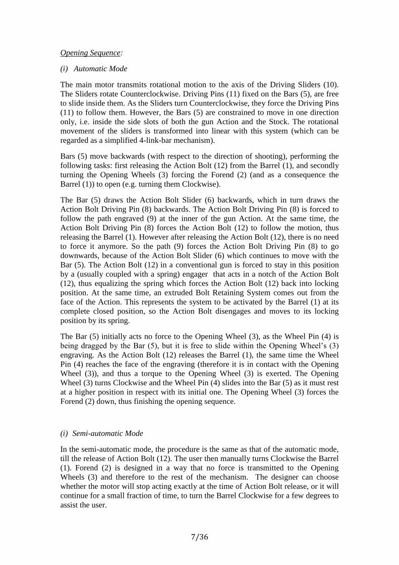
Opening Sequence:
(i) Automatic Mode
The main motor transmits rotational motion to the axis of the Driving Sliders (10).
The Sliders rotate Counterclockwise. Driving Pins (11) fixed on the Bars (5), are free
to slide inside them. As the Sliders turn Counterclockwise, they force the Driving Pins
(11) to follow them. However, the Bars (5) are constrained to move in one direction
only, i.e. inside the side slots of both the gun Action and the Stock. The rotational
movement of the sliders is transformed into linear with this system (which can be
regarded as a simplified 4-link-bar mechanism).
Bars (5) move backwards (with respect to the direction of shooting), performing the
following tasks: first releasing the Action Bolt (12) from the Barrel (1), and secondly
turning the Opening Wheels (3) forcing the Forend (2) (and as a consequence the
Barrel (1)) to open (e.g. turning them Clockwise).
The Bar (5) draws the Action Bolt Slider (6) backwards, which in turn draws the
Action Bolt Driving Pin (8) backwards. The Action Bolt Driving Pin (8) is forced to
follow the path engraved (9) at the inner of the gun Action. At the same time, the
Action Bolt Driving Pin (8) forces the Action Bolt (12) to follow the motion, thus
releasing the Barrel (1). However after releasing the Action Bolt (12), there is no need
to force it anymore. So the path (9) forces the Action Bolt Driving Pin (8) to go
downwards, because of the Action Bolt Slider (6) which continues to move with the
Bar (5). The Action Bolt (12) in a conventional gun is forced to stay in this position
by a (usually coupled with a spring) engager that acts in a notch of the Action Bolt
(12), thus equalizing the spring which forces the Action Bolt (12) back into locking
position. At the same time, an extruded Bolt Retaining System comes out from the
face of the Action. This represents the system to be activated by the Barrel (1) at its
complete closed position, so the Action Bolt disengages and moves to its locking
position by its spring.
The Bar (5) initially acts no force to the Opening Wheel (3), as the Wheel Pin (4) is
being dragged by the Bar (5), but it is free to slide within the Opening Wheel’s (3)
engraving. As the Action Bolt (12) releases the Barrel (1), the same time the Wheel
Pin (4) reaches the face of the engraving (therefore it is in contact with the Opening
Wheel (3)), and thus a torque to the Opening Wheel (3) is exerted. The Opening
Wheel (3) turns Clockwise and the Wheel Pin (4) slides into the Bar (5) as it must rest
at a higher position in respect with its initial one. The Opening Wheel (3) forces the
Forend (2) down, thus finishing the opening sequence.
(i) Semi-automatic Mode
In the semi-automatic mode, the procedure is the same as that of the automatic mode,
till the release of Action Bolt (12). The user then manually turns Clockwise the Barrel
(1). Forend (2) is designed in a way that no force is transmitted to the Opening
Wheels (3) and therefore to the rest of the mechanism. The designer can choose
whether the motor will stop acting exactly at the time of Action Bolt release, or it will
continue for a small fraction of time, to turn the Barrel Clockwise for a few degrees to
assist the user.

8/36
(ii) Manual Mode
By moving the lever, its extension (12a) pushes the Action Bolt (12), which is being
released, acting on the Action Bolt Driving Pin (8) thus forcing the Action Bolt Slider
(6) and the Bar (5) backwards. Upon release, the user can rotate the Barrel as done in
the Semi-automatic Mode.
Closing Sequence:
In case of Manual closing the user turns Counterclockwise the Barrel (1) and the
Forend (2) thus turning the Opening Wheel (3) also Counterclockwise. The Wheel Pin
(4) forces the Bar (5) to move forward, and as a consequence the Action Bolt Slider
(6) and the Action Bolt Driving Pin (8) move forward. Driving Sliders (10) are forced
to turn Clockwise. When the Barrel (1) is closed, the initial position should be
reached.
This happens through the spring that holds the Action Bolt (12) into position when
gun is closed and already exists in a conventional gun. Specifically, as the Barrel (5)
closes, it acts on the extruded part of the Bolt Retaining System, which is connected
with the engager. The engager releases the Action Bolt (12), which is forced to lock
the Barrel (5). As Action Bolt (12) moves, it acts on the Action Bolt Driving Pin (8),
the Action Bolt Slider (6) and the Bar (5). The Bar (5) forces the Wheel Pin (4) and
the Driving Slider (10) to stop at their initial positions. Thus the closing is completed
and the gun is ready for use.
In case of Automatic closing, the Forend should have retractable covers at the upper
position of the inner engraving. When these covers are used, the Opening Wheels (3)
can act with their upper side of their extruded part on the Forend. This way the Barrel
(1) can move Counterclockwise and close.

9/36
(a)
(b)
(c)
Figure 5. Sequential movements of the various parts of Driving Subsystem: (a)
Release of Action Bolt, (b) The Opening Wheels start to turn, (c) The Opening Wheel
have turned 30o.

10/36
(a)
(b)
(c)
Figure 6. Sequential movements of the Opening Wheel and the Wheel Driving Pin:
(a) Release of Action Bolt, (b) Opening Wheels start to turn, (c) Opening Wheel has
turned 30o.

11/36
Mechanical Transmission Subsystem
Shafts positioned inside appropriate extruded cuts of the Driving Sliders (10) force
them to rotate. The main motor provides the motion to these shafts through a Worm-
Gear (the Gear (19) is shown in Fig. 7) transmission, which is not backdriveable. This
would create a problem when the barrel returns to its closed position manually. To
address this potential problem, the motor is decoupled from the remaining
transmission using two clutches, as shown in Fig. 7. The clutches are controlled either
with a spindle motor (Variation I), or with a voice coil (Variation II).
Variation I
Whenever the Button for opening is pressed, the microcontroller sends a signal to the
Spindle Motor (18) to close the Clutching Arms (16). For this reason, it acts through a
screw mechanism to the Driving Cone (17), transforming the rotational motion (of the
motor) to translational (of the Cone). The Clutching Arms (16) are obliged to move
following the peripheral of the cone. It must be noted that the Arms (16) are inside
drawers of the Stock, which forces them to move only linearly, to and from the
Driving Sliders (10). On the Arms (16) preloaded springs act, thus retaining
continuously contact between Arms (16) and Cone (17).
Figure 7. Conceptual design of the Clutching Mechanism for Variation I.
Table II: Parts list for Figure 7
5: Bar 14: Minor Shaft 18: Spindle Motor
10: Driving Sliders 15: Major Shaft 19: Gear
11: Driving Pins 16: Clutching Arms
13: Friction Ring 17: Driving Cone or
Engraved Cylinder

12/36
As the Arms (16) close, they force the Minor Shafts (14) to couple with the Major
Shaft (15) in order torque from the Worm-gear to be transmitted to the Driving Sliders
(10).
When there is no need to transmit any more torque from the motor, the
microcontroller gives a signal to the Spindle Motor (18) to move the Cone (17)
backwards, so the Arms (16) disengage the Shafts.
This way the manual closing and the Semi-automatic and Manual modes can work
without transmitting torque to the Worm Gear and the Motor Assembly.
It is important to include the Friction Ring (13) between the Arms (16) and the Minor
Shafts (14).
The latter can rotate however the Arms cannot. The Friction Ring (13) allows this.
One more important thing is the shape of the teeth of the Minor and Major Shafts.
It is possible because of small inaccuracies, when the system is in rest, their faces not
to match. However with proper machining the surfaces may slide to each other.
Thus, during clutching, if they cannot completely mate, the inevitable rotation from
the Worm Wheel will result them to mate.
Instead of a Driving Cone (17) which acts on the Clutching Arms (16) by its helical
movement, an Engraved Cylinder can be used.
The Cylinder can be set on the shaft of the Spindle Motor and will have appropriate
engravings which the Arms must follow, thus creating their movement.
In this case no spring for Arms will be necessary and the movement of the Cylinder
will be strictly rotational.
Variation II
The only difference between Variation II and Variation I is the use of Voice Coil (20)
instead of the Cone and Spindle Motor, in moving the Clutching Arms (16). Upon
pressing the Button from the user, the microcontroller sends a signal to an amplifier
circuitry that activates the Voice Coil (20). A magnetic field is created forcing the
metallic ends of the Clutching Arms (16) to move inside the Coil (20), thus engaging
the Major with the Minor Shafts.

13/36
Figure 8. Conceptual design of the Clutching Mechanism for Variation II.
Table III: Parts list for Figure 8
5: Bar 13: Friction Ring 16: Clutching Arms
10: Driving Sliders 14: Minor Shaft 19: Wheel
11: Driving Pins 15: Major Shaft 20: Voice Coil
Motor Subsystem
The Motor Assembly (22) includes the Main Motor, which produces the necessary
rotational motion, an Encoder to transmit the Motor’s Shaft position to a
microcontroller, and a Gearbox to reduce the rotational speed of the Motor’s output
shaft thus increasing the torque. The output shaft of the Gearbox is coupled with a
Worm-Gear (19, 24) through a Coupler (23) in order to absorb any vibrations. The
Motor Assembly and the Battery parts are located inside the Stock. Their exact
position depends on specific requirements such us: exact dimensions of the necessary
Motor Assembly and Battery, weight, center of mass, etc.

14/36
Figure 9. Motor Assembly.
Table IV: Parts list for Figure 9
15: Major Shaft 21: Shaft 23: Coupler
19: Wheel 22: Main Motor Assembly 24: Worm
Electronics and Control
A microcontroller (MCU), see Fig. 10, with the necessary electronics is attached in a
small Printed Circuit Board (PCB). The PCB can be located anywhere in the interior
of the gun, as it requires minimal space. Electronics may have the form of THT or
SMD forms, with the latter being extremely small.
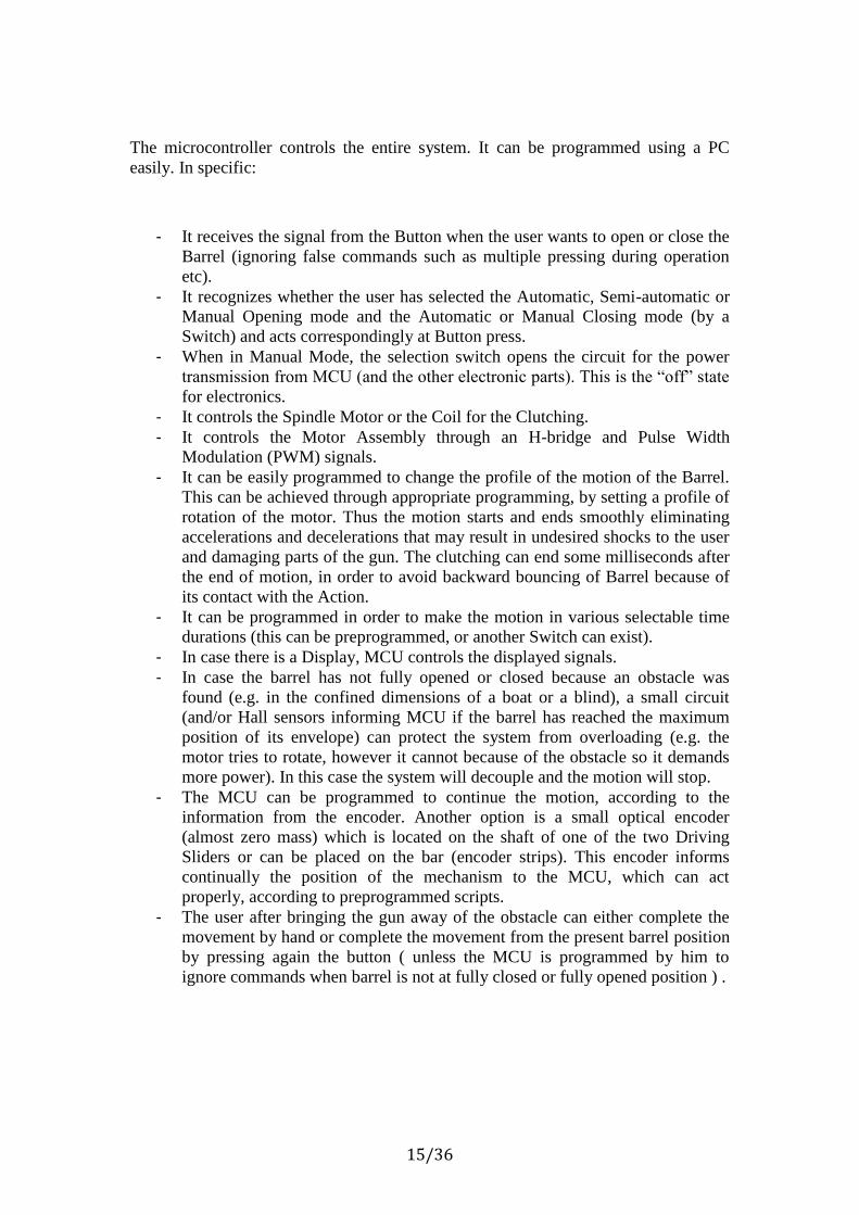
Figure 10. Some electronic components. (a) Voltage Regulators, (b) Atmel MCUs
and (c) Microchip PIC MCUs.
15/36
The microcontroller controls the entire system. It can be programmed using a PC
easily. In specific:
- It receives the signal from the Button when the user wants to open or close the
Barrel (ignoring false commands such as multiple pressing during operation
etc).
- It recognizes whether the user has selected the Automatic, Semi-automatic or
Manual Opening mode and the Automatic or Manual Closing mode (by a
Switch) and acts correspondingly at Button press.
- When in Manual Mode, the selection switch opens the circuit for the power
transmission from MCU (and the other electronic parts). This is the “off” state
for electronics.
- It controls the Spindle Motor or the Coil for the Clutching.
- It controls the Motor Assembly through an H-bridge and Pulse Width
Modulation (PWM) signals.
- It can be easily programmed to change the profile of the motion of the Barrel.
This can be achieved through appropriate programming, by setting a profile of
rotation of the motor. Thus the motion starts and ends smoothly eliminating
accelerations and decelerations that may result in undesired shocks to the user
and damaging parts of the gun. The clutching can end some milliseconds after
the end of motion, in order to avoid backward bouncing of Barrel because of
its contact with the Action.
- It can be programmed in order to make the motion in various selectable time
durations (this can be preprogrammed, or another Switch can exist).
- In case there is a Display, MCU controls the displayed signals.
- In case the barrel has not fully opened or closed because an obstacle was
found (e.g. in the confined dimensions of a boat or a blind), a small circuit
(and/or Hall sensors informing MCU if the barrel has reached the maximum
position of its envelope) can protect the system from overloading (e.g. the
motor tries to rotate, however it cannot because of the obstacle so it demands
more power). In this case the system will decouple and the motion will stop.
- The MCU can be programmed to continue the motion, according to the
information from the encoder. Another option is a small optical encoder
(almost zero mass) which is located on the shaft of one of the two Driving
Sliders or can be placed on the bar (encoder strips). This encoder informs
continually the position of the mechanism to the MCU, which can act
properly, according to preprogrammed scripts.
- The user after bringing the gun away of the obstacle can either complete the
movement by hand or complete the movement from the present barrel position
by pressing again the button ( unless the MCU is programmed by him to
ignore commands when barrel is not at fully closed or fully opened position ) .

16/36
A basic connection between the various components is presented in Fig. 11.
Voltage Regulators drop the DC Battery Voltage to nominal levels for each
subsystem (for example from 11.1V Battery Pack to 9V for Motor and 5V for
Electronics).
Figure 11. Basic interconnections between various electromechanical components.
3.EXPERIMENTAL MEASUREMENTS AND MOTOR
ASSEMBLY SIZING
Experimental measurements took place in our laboratory, using a conventional
over/under gun of a famous and well established maker. This gun was new “out of the
box”(not a single round was fired with it), with very tight “fitting” compared to others
of the same maker which were even slightly used, competition model, 12 gauge , with
75 cm barrel weigh 1.610 gr and “beaver-tail” forend weigh 360 gr (total weight
1.970 gr). That big weight supersizes the situation but is used for demonstration
purposes.
Here must be noted that in the case of side-by-side gun, due to lower barrel-forend
weight and smaller opening angle, the opening time and the required power are
almost half.
The necessary forces, and therefore the necessary torques have been measured.
Measurements for Opening were received at 30 cm from rotation center with the gun
held in vertical (normal) position (therefore gravity acts to help in the opening) and

17/36
(as a capability test) with the gun in horizontal position (held 90o around the axis of
the barrel). At the latter case, gravity does not assist the user. Additionally the torque
for the Action Bolt Unlocking has been measured also. This torque represents the
necessary energy to overcome the spring force which holds the Action Bolt into
Locking position. Before each measurement, both triggers were pulled so the force of
all cocking springs is included. Note that calculations refer to various opening times,
which are presented at each Table next. The total opening time includes Action Bolt
Unlocking and Barrel Opening, and the values are based on the measured torque
applied on the Top Lever and on the Barrel. Generally the opening times are divided
in the proposed estimates: milliseconds for clutching (so it is not included in the total
opening time), about 0.15 sec Action Bolt Unlocking and the rest (according to each
case) Barrel Opening. Driving Sliders may have various rotational angles (it depends
on the needs and the final design) which leads to various angular speed for them.
However the power to perform Action Bolt Unlocking and Barrel Opening is derived
by the physical properties of them.
Measurements and calculations performed also for Closing. In this case, the
measurements were received by pulling the barrel from the bottom part of it , at 50 cm
from rotation center, in order to keep the measuring instrument in a distance from the
forend .The chosen Closing time is 1,35 sec due to the fact that ,during closing ,the
gun stops on the soft area of the hand between the thumb and the pointing finger and a
faster closing can cause an unpleasant shock (while, during opening, the gun is firmly
held). A faster closing can also cause the emptying of the shotshells from the
chambers and the wear of the fitting . It is also recommended during closing for the
action of the gun to be held slightly downwards in order to keep the barrel pointing in
a safe direction after the completion of the closing.
It is noted that the power requirements of the spindle motor or the voice coil is
extremely low compared to the power requirements of the Motor Assembly.
Additionally the driving force for the design concept was the mechatronic subsystem
which unlocks the Action Bolt and opens or closes the Barrel. Thus the calculation for
the power demands for the Clutching Subsystem is omitted. The Safety Factor is set
high in order to cover also this.
Tables 5-8 summarize the findings and also calculations of some necessary values.
Table V. Experimental measurements and calculations for Action Bolt Unlocking
( Angle 30o ) . Mean value of 15 efforts. Unlocking time 0.15 sec.
Measured Force (kg) 2,41
Distance from Rot. Center (m) 0,06
Torque (Nm) 1,419
Angular Speed (rad/sec) 3,493
Power (W) 4,955
Safety Factor 1,20
Calculated Power 5,946

18/36
Table VI. Experimental measurements and calculations for Vertical (Normal) Barrel
Opening ( Angle 45o ) .Mean value of 30 efforts. Opening time 0.60 sec.
Measured Force (kg) 1,28
Distance from Rot. Center (m) 0,3
Torque (Nm) 3,767
Angular Speed (rad/sec) 1,309
Power (W) 4,931
Safety Factor 1,20
Calculated Power 5,917
Table VII. Experimental measurements and calculations for Horizontal Barrel (No
gravity assist) Opening ( Angle 45o ). Mean value of 30 efforts. Opening time 0.85 sec.
Measured Force (kg) 2,51
Distance from Rot. Center (m) 0,3
Torque (Nm) 7,387
Angular Speed (rad/sec) 0,924
Power (W) 6,826
Safety Factor 1,20
Calculated Power 8,191
Table VIII. Experimental measurements and calculations for Vertical (Normal) Closing
of the Barrel ( Gravity acts to the opposite direction of the movement ) ( Angle 45o ).
Mean value of 30 efforts. Closing Time 1.35sec
Measured Force (kg) 2,60
Distance from Rot. Center (m) 0,5
Torque (Nm) 12,753
Angular Speed (rad/sec) 0,582
Power (W) 7,422
Safety Factor 1,20
Calculated Power 8,906

19/36
For the calculations the following formulas were used
Torque:
T F r
Where
T (Nm) is torque
( )F N is measured force in kg ( 21 1 9.81 secN kg m )
r (m) is distance of Point of Force Application from Rotation Center
Angular Speed:
t
Where
( / sec)rad is the angular speed
(rad) is the opening angle
(sec)t is the opening time
Power P T
Where
P (W ) is power
T (Nm) is torque
( / sec)rad is the angular speed
The above mentioned power does not include a Safety Factor. Alternatively, it can be
considered as the power when the Safety Factor equals 1.00. For design purposes, the
necessary power with Safety Factor 1.20 (that means necessary power 20% more than
the measured one) has been calculated also.
The CAD design for motor set (motor, gearbox, encoder), worm-gear and battery is
based on the selection of the case of Horizontal Barrel Opening position with Safety
Factor 1 as basic situation. It is an oversizing situation by default (the gravity does not
assist the opening).
4. WORM GEAR SET
Worm Gear is the interface system between the motion that originates from the Motor
Assembly and the motion imparted on the Driving Sliders (10). Additionally it lowers
the rotational speed from the Shaft (21) after the Coupler (23) and the same time it
increases the Torque to the Driving Sliders (10).

20/36
This mechanism allows the motion transmission from one direction only (e.g. from
the Motor Assembly). This is added to the general problem of non-backdriveability,
i.e. no motion from the Mechanism should be transmitted to the Worm Gear Set and
the Motor Assembly. For this reason the Clutching Subsystem has been created.
Companies that make worm-gear systems are presented at the end of this Section.
This is an indicative list, as globally many companies produce worm-gears including
customized solutions. Therefore there was no point in referring to particular Worm
Gear Sets. It is concluded that a Worm Gear mechanism with a reduction ratio of
about 30:1 inside the volumetric permissible envelope of the gun, is feasible.
References:
(1) www.khkgears.co.jp/en/index.html
(2) www.framo-morat.com
(3) bostongear.com
(4) www.qtcgears.com
5. BATTERIES After examination of various battery technologies, Li-Po batteries were selected as the best choice, since they are characterized by:
- Very high specific energy (about 140 Wh/kg, depending on the manufacturer)
- Capability of providing huge Amps, necessary for starting the motor
- Low mass and volume
- High cycle life (even more than 1000 cycles in some cases)
- Negligible memory effect
- Small charging times
- Generally accepted working temperatures from -20oC up to 60oC
- Loss of power in storage : less than 5% per month ( almost 2 years from full)
Another crucial part is that by design, they can have any shape required, making them
perfect for being positioned in the Stock, which is non-orthogonal. The battery
producer can customize the battery according to the specific needs.
In case the temperature is below -20oC, Li-Po still works just with lower capacity .
The use of thermal insulation, especially with materials arising e.g. from aerospace
technology will provide a stable environment for the battery packs. A thin sheet of
this material around the battery, of some millimeters will solve any possible problem.
Also the use of Heavy Duty Battery Packs, will ensure the proper function of the
system according to the requirements in extreme conditions, however this design

21/36
should be of such way in order not to change the physical characteristics of the Stock
substantially.
Li-Po are established batteries, used in many applications that include laptops, mobile
phones or RC models. Additionally there are special chargers that facilitate the
charging process. In the near future, it is expected that Li-Po batteries will improve
further due to the large R&D efforts in this area. In fact, recently MIT has discovered
a method to charge Li-Po batteries in few seconds (depending on the capacity) which
leads to designs with smaller batteries with lower mass, which however can be
charged so fast rendering the drawback of capacity to a low importance matter.
To find the approximate number of opening cycles, we followed the following procedure. The necessary power to use the mechanism each time the Button is pressed is:
I
b(mAh) 1000 I( A)
t(s)
3600
Where
I
b (mAh) is the necessary power each time the Button is pressed
I ( A) is the starting current for the motor
(sec)t is the time the motor is working
Apparently the above mentioned equation over-computes the necessary power, as the
average current drawn is only a fraction of the starting current of the motor.
The number of times that the system will work without need of recharging (repeats)
are:
R I
c(mAh)
Ib(mAh)
Where
R is the number of repeat times
I
b (mAh)
is the necessary power each time the Button is pressed
I
c(mAh)
is the power capacity of the battery
References:
(1) Graupner, Instructions and Warnings Relating to the Use of LiPo Batteries
(2) KRC Newsletter Special Edition, “LiPo Batteries in Cold”
(3) www.3w-modellmotoren.com
(4) http://www.bikudo.com/product_search/details/104849/minamoto_3_7v_lithiu
m_polymer_battery.html
(5) http://www.batteryuniversity.com/partone-15.htm
(6) http://www3.towerhobbies.com/

22/36
6. CASE STUDIES
According to the measured and calculated values 3 case studies have been selected. In each case, a number of necessary Motor Assemblies (Motor, Gearbox, Encoder) are selected and the appropriate Battery Pack.
The number of available repeated uses without recharging the battery has been found.
As it is obvious from the measurements (Section 3), power needs for Safety Factor 1.20 were well above corresponding values for Safety Factor 1.
Thus for demonstration purposes only SF 1.20 was chosen for the decision of Motor Assembly.
However when the Motor Assembly is chosen according to the power needs of Horizontal Opening or the Normal Closing, these power requirements are far above of the Action Bolt Unlocking power requirements, thus they are the selection drivers.
The use of SF 1.20 supersizes the selections, adding a safer margin to estimates.
Also supersizing exists for the energy consumption, as the starting current which is used for the calculation, acts only for the first milliseconds of movement, and then its value falls.
However for our purposes starting currents is used for the whole procedure (e.g. for the total motion time).
According to this, the following cases are presented:
(a) Action Bolt Unlocking 0.15 sec and Horizontal Opening 0.85 sec, Total time 1
sec. Opening power demands prevail.
(b) Action Bolt Unlocking 0.15 sec and Vertical Opening 0.60 sec, Total time
0.75 sec. Action Bolt Unlocking power demands prevail.
(c) Action Bolt Unlocking 0.15 sec and Vertical Opening 0.60 sec, Total Opening
time 0.75 sec. 1.35 sec Closing Time. Closing power demands prevail.
Notes on the tables:
- Only Maxon Motors uses the term “Starting Current” in motor datasheets.
Other firms provide “Nominal Voltage” and “Terminal Resistance”. In the
latter case, the starting current is the division of Voltage to Resistance and has
been computed.

23/36
- Necessary ratio field is the necessary gear reduction ratio of Motor Assembly,
if the reduction ratio of Worm-Gear (see Sec. 4) is 30:1. The gearbox is
selected based on this number.
- Some companies do not provide prices.
- Encoders have little information about weight and dimensions, so assumptions
where used whenever possible. However this part adds no substantial weight
or volume.
- Total numbers is a sum of the respective mass, length or volume of each part
of Motor Assembly and Battery, whenever this was possible.
- The Spindle Motor (18) and Coil (20) consumptions, as well as the power
consumption of electronics are not included. They are minimal compared to
the Motor Assembly consumption.
See App. B for Spindle Motors information.
Information for Motor Assemblies can be found at:
(1) www.maxonmotor.com
(2) www.faulhaber-group.com
(3) www.micro-drives.com

24/36
(a) Action Bolt Unlocking 0.15 sec and HORIZONTAL OPENING 0.85 sec,
TOTAL TIME 1 sec.
SET Company Model W VNom. Torque
(mNm)St. Cur (A)
Diam.
(mm)
Length
(mm)
Volume
(cm3)
Weight
(g)Cost (€)
i (Nec.
Ratio)
1 Faulhaber 2232009R 9.35 9 10.00 4.206 22.0 32.2 12.23 62 N/A 21.58
Motor
SET Model iMax Torque
(Nm)
Diam.
(mm)
Length
(mm)
Volume
(cm3)
Weight
(g)
Cost
(€)
1 20/1 23 0.50 20.0 23.5 7.38 38 N/A
Gearbox
SET Model Counts Width HeightLength
(mm)
Weight
(g)
Cost
(€)
1 IE2-400 100 13.0 N/A N/A 20 N/A
Encoder
SETWeight
(g)
Length
(mm)
Volume(
cm3)
Cost
(€)
1 120 55.7 19.61 N/A
Total of Motor Assembly
SET Company V mAh C L (m) W (m) H (m)Volume
(cm3)
Weight
(Kg)Repeats
Repeats
(Unlock
only)
Cost (€)
1 Flight Power 11.1 2500 25 0.129 0.040 0.022 113.520 0.208 2140 8559 94.92
Batteries List
SETWeight
(kg)
Volume
(cm3)
Cost (€)
1 0.328 133.133 N/A
Total

25/36
(b) Action Bolt Unlocking 0.15 sec and VERTICAL OPENING 0.60 sec,
TOTAL TIME 0.75 sec.
SET Company Model W VNom. Torque
(mNm)Cur (A)*
Diam.
(mm)
Length
(mm)
Volume
(cm3)
Weight
(g)Cost (€)
i (Nec.
Ratio)
1 Maxon 110158 6.00 9 6.52 2.380 22.0 31.9 12.12 54 33.27 13.04
2 Maxon 220427 6.50 9 10.70 2.210 24.0 31.9 14.42 71 56.07 7.95
3 Faulhaber 2232009R 9.35 9 10.00 4.206 22.0 32.2 12.23 62 N/A 8.50
Motor
SET Model iMax Torque
(Nm)
Diam.
(mm)
Length
(mm)
Volume
(cm3)
Weight
(g)
Cost
(€)
1 134158 14 0.50 22.0 32.2 12.23 55 66.60
2 232766 14 0.30 22.0 29.5 11.21 35 38.27
3 20/1 9.7 0.50 20.0 23.5 7.38 38 N/A
Gearbox
SET Model Counts Width HeightLength
(mm)
Weight
(g)
Cost
(€)
1 110520 100 33.7 22.0 N/A 20 48.53
2 110520 100 33.7 22.0 N/A 20 48.53
3 IE2-400 100 13.0 N/A N/A 20 N/A
Encoder
SETWeight
(g)
Length
(mm)
Volume(
cm3)
Cost (€)
1 129 64.1 24.35 148.40
2 126 61.4 25.63 142.87
3 120 55.7 19.61 N/A
Total of Motor Assembly
SET Company V mAh C L (m) W (m) H (m)Volume
(cm3)
Weight
(Kg)Repeats
Repeats
(Unlock
Only)
Cost (€)
1 Thunder Power 11.1 1320 20 0.065 0.034 0.019 41.990 0.084 2662 7987 34.76
2 Thunder Power 11.1 1320 20 0.065 0.034 0.019 41.990 0.084 2867 8601 34.76
3 Thunder Power 11.1 1800 30 0.092 0.031 0.025 71.300 0.146 2054 6163 50.39
Batteries List
SETWeight
(kg)
Volume
(cm3)
Cost (€)
1 0.213 66.344 183.16
2 0.210 67.622 177.63
3 0.266 90.913 N/A
Total

26/36
(c) Action Bolt Unlocking 0.15 sec and Vertical Opening 0.60 sec,
TOTAL OPENING TIME 0.75 sec. , CLOSING TIME 1.35 sec.
SET Company Model W VNom. Torque
(mNm)St. Cur (A)
Diam.
(mm)
Length
(mm)
Volume
(cm3)
Weight
(g)Cost (€)
i (Nec.
Ratio)
1 Faulhaber 2232009R 9.35 9 10.00 4.206 22.0 32.2 12.23 62 N/A 42.51
Motor
SET Model iMax Torque
(Nm)
Diam.
(mm)
Length
(mm)
Volume
(cm3)
Weight
(g)
Cost
(€)
1 20/1 43 0.50 20.0 28.6 8.98 48 N/A
Gearbox
SET Model Counts Width HeightLength
(mm)
Weight
(g)
Cost
(€)
1 IE2-400 100 13.0 N/A N/A 20 N/A
Encoder
SETWeight
(g)
Length
(mm)
Volume(
cm3)
Cost
(€)
1 130 60.8 21.21 N/A
Total of Motor Assembly
SET Company V mAh C L (m) W (m) H (m)Volume
(cm3)
Weight
(Kg)Repeats Cost (€)
1 Flight Power 11.1 2500 25 0.129 0.040 0.022 113.520 0.208 1019 94.92
Batteries List
SETWeight
(kg)
Volume
(cm3)Cost (€)
1 0.338 134.734 N/A
Total
The additional mass due to the mechatronic mechanism will have a minimal effect in
the total mass of a conventional gun. The volumes where the parts reside, substitute
existing material, and there will be even some small gaps to enable the movements
(linear and rotational) of the various components. Thus a small reduction of mass is
possible.
Therefore the main mass problem is concentrated in the Stock, where in the wooden
cavity the motor system plus the batteries and additional electronics are inserted. The
total mass increase will be small (perhaps 50-100 g as a rough estimate), and it
depends on the materials to be used and of course on the Motor Assembly selection.
The use of novel light materials (but with approved strength and robustness), which
can substitute the wood of the Stock, may lower substantially the mass increase.

27/36
7. CONCLUSIONS
A novel mechanism for automated movement of the Barrel with minimal effort from
user has been presented. This mechanism can be easily adapted to the current form of
conventional guns without any severe modifications. The normal functionality of guns
is not affected in any case.
The description of the mechanism with relevant schematics was presented. Three
Modes for Opening have been analyzed, namely (a) the Automatic Mode (Automatic
Action Bolt Unlocking and Automatic Opening of the Barrel), (b) the Semi-automatic
Mode (Automatic Action Bolt Unlocking, Manual Opening of the Barrel), and (c) the
Manual Mode (Manual Action Bolt Unlocking and Manual Opening of the Barrel).
Additionally, two Closing Modes have been examined, the Automatic Closing and the
Manual Closing. Two clutching variations of the mechanism have been proposed also.
The design of the presented mechanism can be altered up to a high degree if needed,
by using different types of parts and materials such as chains, transmission belts, steel
threaded cables, levers, axes etc.
The experimental measurements in our laboratory were presented. According to them,
proposals for the Battery and Motor Assembly are derived for three cases. The
existence of solution is affirmed. The limit of 2000 repeats for opening can be easily
achieved even if the gun is held in horizontal position. The case of Automatic Closing
has been also examined.
A novel mechanism using mechatronic components for the opening and the closing
of a gun, retaining compatibility with user habits on conventional ones, is regarded as
absolutely feasible.

28/36
APPENDIX A
The following appendix describes one by one every component of the mechanism
alphabetically.
Bar
The Bar moves linearly inside cavities of the Action and the Stock, transforming the
rotational movement of the Driving Slider to linear. (A) is the position where the
Wheel Pin can move, (B) is the position where the Action Bolt Slider is fixed with
screws and (C) is the extruded pin, which connects the Bar with the Driving Slider.
(A) has diagonal shape, because as the Wheel Pin acts force to the Opening Wheel,
the Pin must change its initial height.
Barrel
Barrel retains its conventional form. (A) is the point where it can rotate around the Pin
of Action.

29/36
Action (modified)
The action is a conventional gun Action that has been properly modified. (A) Is where
the Action Pin exists and the Opening Wheels can rotate. Additionally it is the point
where the Barrel can rotate. (B) is the cavity where the extruded part of Opening
Wheels moves. (C) is the cavity for the Bars, from outside. (D) is the cavity for the
Bars from inside and (E) is a stop for the Action Bolt movement during Unlocking.
Stock (modified)

30/36
(A) is the outside modifications, allowing the Bar to move inside. (B) is the drawer
where Bar can linearly translate. (C) is the position where the Driving Sliders can
rotate, (D) is the position for Spindle Motor (only for Variation I), (E) is the location
where the Clutching Arms can translate and (F) the support for the Major Shaft. The
Motor Assembly and the Battery can be positioned in correspondence with
requirements.
Clutching Arms
The Clutching Arm has a shape, (A), capable to drive the Minor Shafts. (B) is
constrained into a cavity. (C) either follows the Cone (Variation I), or moves inside a
Coil (Variation II).

31/36
Clutching Cone
This cone is used in Variation I to force Clutching Arms to open or close, thus
engaging/disengaging the clutch. Alternatively it can have an engraving, which the
Arms have to follow.
Forend (modified)
The Forend is connected with the Opening Wheel at (A) and assists the Barrel
Movement. In Automatic Mode the Opening Wheels push the Forend downward
during opening. During closing the force from user to the Forend is transferred to the
Opening Wheels thus reversing the mechanism. In Semi-Automatic Mode however,
the user opens the Barrel with hand, thus the engraving of (A) allows the rotation to
be performed without acting force to the Opening Wheels and consequently to the
gears and Motor Assembly. On the upper side of the engraving there are retractable
covers to be used in the Automatic Closing Mode.
Engraving of Action
The engraving is actually part of the Action. It forces the Action Bolt Driving Pin to
follow a certain path. This way the Action Bolt unlocks initially and the Pin moves
with the Action Bolt Slider. At closing it reverses the movement.

32/36
Action Bolt (modified)
The Action Bolt is a modified conventional one. The notch (A) is retained in order to
allow the Bolt Retaining System to move in it freely. (B) is diagonal in one side to
allow the Action Bolt Driving Pin to fall, following the engraving of the Action. (C) is
the slot for the Top Lever Extension. (C) is in this position, so in Automatic and
Semi-Automatic Mode the Action Bolt Unlocking acts no force to the extension,
whereas in Manual Mode, the extension can act to the Action Bolt.
Action Bolt retains its original purpose, this of locking the Barrel. By default there is
a spring that acts in order to keep it in locking position, and an engager is used to lock
in a notch when opening the Barrel, thus equalizing the force of the spring. It is the
force of this spring that is used to reset the mechanism to its original position, when
the Barrel is closed and the engager unlocks from the notch .
Action Bolt Slider
Action Bolt Sliders move with the Bar and force the Action Bolt Driving Pins to
follow them. (A) is where the Pins are allowed to move, and (B) is the positions for
Screws for fixing the Slider together with the Bar.

33/36
Major Shaft
Major Shaft transmits the torque from the Worm-Gear to the Minor Shaft. (A)
connects it with the Wheel. (B) exists in order to couple easier with the Minor Shafts.
Minor Shafts
The Minor Shafts transmit torque form the Wheel to the Driving Sliders. (A) Allows
the Shaft to cooperate with the Slider. (B) allows the Clutching Arms to operate for
the translational movement and (C) allows the coupling with Major Shaft.

34/36
Opening Wheel
The Opening Wheel interfaces with the Forend. (A) is inserted in the Forend in order to act on it when rotating. Additionally, at Manual closing (in Automatic or Semi –Automatic Opening Mode), Forend forces the Opening Wheels to rotate in order to reset the mechanism ,while in Automatic Closing Mode the retractable covers of the Forend force the Forend to follow the Opening Wheels. (B) is the rotation point. (C) is the engraving of the Wheel, where the Wheel Pin moves.
Sliding Driver
The Driving Sliders transform in conjunction with the Bar the rotational movement
from the Motor Assembly and Worm-Gear to linear. (A) is the position where the
Minor Shafts are positioned capable to move inside and outside during clutching. The
shape allows the transmission of torque from Shafts to the Sliders. (B) is where the
extruded pin of the Bars is allowed to move. (C) is used in the wall of Stock in order
to position the Slider (small bearings can be used for greater robustness).

35/36
Trigger Assembly
This part remains unmodified.
Manual Opening Extension
This is the extension of the Manual Opening. (A) has the shape of the Action Bolt
slot. (B) is the extension from Manual Opening. Its shape allows the user only in
Manual Mode to push the Action Bolt for Unlocking and does not follow the Action
Bolt movement when the mechanism in non-manual modes.
Voice Coil
Voice Coil is used in Variation II. A magnetic field is created when current runs
inside the cables, thus forcing the Clutching Arms to move.

36/36
APPENDIX B
Spindle Motors are small, have low power demands and provide adequate torque.
Selections from Faulhaber Group have been made and presented in Table B-I. Two
kinds interest: the one has the classical form with the ration of Length to Diameter
higher than one and one flat form with the opposite. In any case the following list is
just indicative. A rotational to linear mechanism should be included at the end of
motor shaft. Starting Current is in most cases about 0.1A which is too low to impose
any substantial problem. It is certain that motors with lower consumption can be
found in the market.
Table B-I. Indicative list of Spindle Motors.
Model Type Length(mm) Diam.(mm) Weight(g) Power St.Current(A)
1506006SR IE2 Flat 7.8 15 7.1 0.170 0.123
1506006SR Flat 5.5 15 4.3 0.150 0.109
0515006B Classic 14.6 5 1.5 0.43 0.380