bpw trailer axles and suspensions axles and... · bpw trailer axles and suspensions ... 3.2.3. disc...
TRANSCRIPT

Mai
nten
ance
Inst
ruct
ion
s B
PW
-W 3
3111
102e
BPW Trailer Axles and Suspensions
MAINTENANCE INSTRUCTIONS
BPW BERGISCHE ACHSEN

2 3BPW�W 33111102e BPW�W 33111102e
1. IMPORTANT INFORMATION
1.1. GeneralThe following maintenance instructions apply to BPW trailer axles and BPW suspensions for drawbar and semi�trailers (manufactured from 1982 onwards). They are part of theTerms and Conditions for the ECO Plus Warranty (see warranty documents atwww.bpw.de).
Carry out the latest maintenance instructions in accordance with the prescribed inter�vals in order to maintain the safe operation and roadworthiness of the vehicle. Thelatest version of the maintenance instructions can always be found at www.bpw.de. Thelatest printed version is available by post on request. The relevant operation and serviceregulations of the vehicle manufacturer and the manufacturers of other vehicle parts mustalso be adhered to.
These maintenance intervals are set out in calendar weeks and are listed to coincide withstatutory testing requirements.
1.2. Maintenance, Repair and Spare PartsRectification of any discovered defects or replacement of worn parts should be carried outby a BPW Service Centre or BPW Direct Service Partner unless the vehicle owner has theappropriate personnel facilities, equipment and workshop manuals available and posses�ses an official certificate to perform interim inspections or special brake inspections.
We strongly recommend that only genuine BPW parts, brake linings in particular, are usedwhen fitting spare parts. Parts authorised by BPW for trailer axles and axle units are regu�larly subjected to special inspections. BPW accepts product responsibility for them.
BPW is unable to determine whether all third party product can be used with BPW traileraxles and axle suspensions without any safety risk; this also applies even if an authorisedtesting organisation has accepted the product.
The ECO Plus Warranty (see warranty documents) will cease to apply if spare parts otherthan genuine BPW spare parts are used.
1.3. Definition On-Road / Off-Road The term "On�Road" refers to roads having a sealed and metalled surface, in other wordswith an asphalt or concrete surface. Gravel roads are regarded as being Off�Road. A vehi�cle is also regarded as being in Off�Road operation even if it departs from sealed surfacesunder operating conditions for only short periods. Off�Road operation is assumed in allcases in tippers and vehicles with comparable applications.
1.4. Latest VersionThe latest maintenance instructions are dated 01.12.2011 and replace maintenance instruc�tions BPW�W 33111101e. All previous maintenance instructions become invalid. We reservethe right to make any changes.
Contents: Page
1. IMPORTANT INFORMATION
1.1. General 31.2. Maintenance, repair and spare parts 31.3. Definition On�Road / Off�Road 31.4. Latest version 3
2. SAFETY INSTRUCTIONS 4
3. BPW TRAILER AXLES / BPW STEERING AXLES
3.1. Lubrication 63.2. Maintenance Work and Visual Inspection
3.2.1. General 213.2.2. Drum brakes 223.2.3. Disc brakes, brake types TSB 3709, TSB 4309, TSB 4312 363.2.3. Disc brakes, brake types SB 3308, SB 3745, SB 4309, SB 4345 46
4. BPW AIR SUSPENSION
4.1 Overview Lubrication and Maintenance Work, Visual Inspection 604.2 Lubrication 664.3 Maintenance Work and Visual Inspection 66
5. BPW MECHANICAL SUSPENSIONS (LEAF SPRINGS) SERIES VA, VB, VG
5.1 Overview Lubrication and Maintenance Work, Visual Inspection 765.2 Lubrication 785.3 Maintenance Work and Visual Inspection 79
6. BPW MECHANICAL SUSPENSIONS (LEAF SPRINGS) SERIES W, BW, GW
6.1 Overview Lubrication and Maintenance Work, Visual Inspection 826.2 Lubrication 846.3 Maintenance Work and Visual Inspection 85

5BPW�W 33111102e4
2. SAFETY INSTRUCTIONS
BPW�W 33111102e
The following instructions should also be adhered to by the driver in addition to the statutory regulations:
In case of a new vehicle: – After the first run under load conditions and after each wheel change :
• Check wheel nuts for firm seating using a torque wrench. See point 1 on page 24, 38, 48.
� After the first two weeks (after the first runs under load conditions):• Check that the bolt connections of the spring attachments and axle steering devices
are secure, depending on the application (On�Road or Off�Road). Observe the stipulated tightening torques.
• Air suspensions: see 4 to 9 page 68 � 73
• Leaf�spring suspensions: see 2 and 4 to 7 page 79 � 80
see 1 and 3 page 85
Prior to each run:– Air reservoir of the brake and air suspension set at operating pressure.
– Visual inspection:• Tyre pressures
• Wheel fastenings
• Check operation of lighting and braking systems
• Drum brake: Check the brake pad/lining thickness when the brake pad/lining wear indicator is in the horizontal position.
• Disc brake: Check the remaining brake pad / lining thickness.Type TSB: The thickness of the remaining pad can be determined by the position of
the caliper in relation to the brake carrier (see page 39).Type SB: The thickness of the remaining pad can be detected by the position of
the brake caliper in relation to the stationary guide sleeve (see pages 49 � 50).
• Check that the air suspension has reached ride height and the air bags are not creased. This also applies after rapid loading or unloading.
• Normal ride level of the air bags, check air bags are not creased. This also applies to rapid loading or unloading.
In the event of frost daily or in accordance with manufacturer’s instructions:– Drain off condensation water via the drainage valve at the bottom of the air reservoirs.
– Check the valve system.
Quarterly:– Clean line filter (in accordance with manufacturer’s instructions).
Proper use of the braking system:– In the event of premature wear of the brake pads, a tractor/trailer harmonisation (accor�
ding to ISO 20918 on braking threshold pressures for heavy commercial vehicle combi�nations) is to be carried out.
– To maintain the efficiency of the braking system, regular use of the wheel brakes with the appropriate level of heat generation is recommended.
– Before proceeding with an HU or SP (PTI), the braking system performance where appli�cable, must be measured (see ISO 7634).
– The appropriate installation and operating instructions for BPW brake components (see www.bpw.de) should be observed.
We wish you a safe journey!

5 2 2 3
1
3
5
5
2
4
4
76
3. BPW TRAILER AXLES / BPW STEERING AXLES
Series H / KH / NH
Series ...LL
Series SH / SKH
1 Steering knuckle bearing, top and bottom 1
2 Brake camshaft bearing, outer and innerLow maintenance camshaft bearingfrom year of manufacture 1993
22
Outside Europe 2Conventional brake camshaft bearingup to year of manufacture 1992 2 2
3 Slack adjusters manual 3
33
Outside Europe 3
4 Brake shoes with closed anchor eye 4
5 ECO Plus 2 and ECOPlus Unit:5
55
5
ECO Unit 5Outside Europe 5
Conventional hub bearing 5
For positions 1 to 3
The use of liquid lubricants is not permitted!1) After a long idle period, prior to initial operation actuate the brake lever and lubricate the
brake camshaft bearing.2)
pressure grease is necessary.
Overview
Dep
end
ent
on in
stal
latio
n
Eve
ry 2
6 w
eeks
1) 2
)
Ann
ually
Eve
ry 2
yea
rs
Tra
iler
axle
s
Eve
ry 3
yea
rs
afte
r ev
ery
3 ye
ars
Late
st e
very
3
year
s or
min
. ev
ery
500,
000
km2)
Eve
ry 1
2 w
eeks
Initi
ally
1)
commendation. Does not affectwarranty
At everybrakelining
ment, 2)
Late
st
annu
ally
1)
Late
st e
very
2
year
s
3.1. Lubrication

98
3. BPW TRAILER AXLES / BPW STEERING AXLES
BPW�W 33111102e BPW�W 33111102e
AAuuttoommaattiicc ssllaacckk aaddjjuusstteerr EECCOO--MMaasstteerr(from year of manufacture 5/91)– every year and with each brake lining
change in On�Road use –– every 6 months in Off�Road use and in use
outside Europe –
Remove rubber seal cap. Grease withBPW special longlife grease ECO�LiPlus
(approx. 80 g) until sufficient new greaseemerges from the adjustment bolt.
Turn back adjustment screw (keep clutchsleeve pressed down) by approx. one turnusing a ring spanner. Actuate the brakelever several times by hand. The adjustment must be carried outsmoothly. If necessary, repeat severaltimes.
Once again only use BPW special longlifegrease ECO�LiPlus. Replace seal cap.
Adjust the brake � see relevant workshopmanual.
2 BBrraakkee ccaammsshhaafftt bbeeaarriinngg,, oouutteerr aanndd iinnnneerrLLooww mmaaiinntteennaannccee bbrraakkee ccaammsshhaafftt bbeeaarriinngg (from year of manufacture 1993)– every year and with each brake lining
change in On�Road use –– every 6 months in Off�Road use and in use
outside Europe –
Use only BPW special longlife grease ECO�LiPlus until fresh grease emerges from the bearing points.
CCoonnvveennttiioonnaall bbrraakkee ccaammsshhaafftt bbeeaarriinngg(up to year of manufacture 1992)– quarterly –(and prior to initial operation after a long idle period!)Grease lubrication nipple with BPW special longlife grease ECO�LiPlus untilfresh grease emerges from the bearingpoints.
TTrraa
iilleerr
aaxxllee
ss
Note: After cleaning the vehicle with high� pressure cleaners, all lubrication points must be relubricated.
1 SStteeeerriinngg kknnuucckkllee bbeeaarriinngg,, ttoopp aanndd bboottttoomm– every 6 weeks –
Lift axle in order to relieve the steeringpivot bearing. Grease lubrication nipplewith BPW special longlife grease ECO�LiPlus until fresh grease emerges from the bearing points.
�
3 SSllaacckk aaddjjuusstteerrss ((mmaannuuaall))– quarterly –
Grease lubrication nipple with BPW special longlife grease ECO�LiPlus untilfresh grease emerges.
�
3
3
2
2
4 BBrraakkee sshhooeess wwiitthh cclloosseedd aanncchhoorr eeyyee– every 2 years and with each brake lining
change –
Clean the bush and roller, check for wearand, if necessary replace. Smear BPWspecial longlife grease ECO�LiPlus ontobearing points of brake shoe.
3.1. Lubrication

11BPW�W 33111102e10
3. BPW TRAILER AXLES / BPW STEERING AXLES
BPW�W 33111102e
TTrraa
iilleerr
aaxxllee
ss
Position 1 Position 2Important!Do not use an impact driver -bayonet lock.
Undo the cap by turning it anti�clock�wise by approx. 30° from position 1 toposition 2.When turned further the hub cap liftsclearly away from the ECO Unit and can be removed by pulling it away.
Remove the hooked spring ring and retaining key from the axle bolt.Unscrew the axle bolt, pulling the complete ECO Unit off the bearing seats of the axle stub as you do so.Dismantle the ECO Unit � see the corresponding workshop manuals.
5 EECCOO PPlluuss 22 UUnniitt– for the first time after 5 years in On�Road
use, or every 3 years in Off�Road use in Europe, then at least every 3 years depending on operating conditions –
– every 2 years in On�Road use or every year in Off�Road use outside Europe –
Prevent the vehicle from rolling away.Remove the wheel.Unscrew the cap with a 120 mm capspanner.
Clean the tapered roller bearings thoroughly (e.g. with diesel oil), dry themand check if they can be re�used. Fit anew shaft seal.(Recommendation: Renew the taperedroller bearings after 5 years in On�Roaduse and after 3 years in Off�Road use.)
Clean the grease cartridge and fill it onboth sides up to the edge with BPWspecial longlife grease ECO�LiPlus. It isimportant to ensure that it is filled withoutany trapped air or cavities.Apply a ring�shaped bead of grease to therunning surfaces of the bearing outer races(see arrows in illustration below). When BPW grease applicators are used,there is no need to fill the grease cartridgeor to apply the bead of grease.Mount the ECO Unit.Clean the bearing seats of the axle stub(metal must be bright, dry and free fromgrease). Apply BPW ECO ProtectionGrease as thin as possible and around the entire area. Bare metal surfaces areprohibited after application.
ECO Plus 2 Unit
�
3.1. Lubrication

13BPW�W 33111102e12
3. BPW TRAILER AXLES / BPW STEERING AXLES
BPW�W 33111102e
TTrraa
iilleerr
aaxxllee
ss
Position 1 Position 2
Insert the hooked spring ring into thegroove of the hexagon profile of the axlebolt. Make sure that the hooked spring ringassembly is correctly seated in theannular groove of the axle bolt.
Insert a new O�ring into the groove in thewheel hub.
Apply a thin layer of BPW ECO�LiPlus
special long�life grease to the cap in thearea of the O�ring contact surface and thebayonet fitting.Screw on the cap with a 120 mm capspanner.
Important!Do not use an impact driver -bayonet lock.
Push on the cap, see position 1.Press on the cap and turn it by approx.30° in a clockwise direction to lock it inplace.A tight seat is provided when position 2 is reached.
Apply only a thin layer of BPW ECO�LiPlus
to the threaded hole in the axle stub.Important!Do not apply too much grease!It is necessary to make sure that theaxle bolt can be completely screwedinto the axle stub. Mount the ECO Unit. Guide the toothedlock washer into the hole in the axle stub.The position of the pin can be seen by thepunched�in BPW logo in the recess of theaxle bolt.
�
Tighten the axle bolt (46 mm) at the sametime as turning the ECO Unit until the axlebolt torque limiter operates. (Do not turn back the axle bolt.)
Important!Do not use an impact driver.
Insert the retaining key into the recess in the axle bolt and the gearing of thetoothed lock washer. (Do not turn back the axle bolt.)
�
3.1. Lubrication

1514
3. BPW TRAILER AXLES / BPW STEERING AXLES
BPW�W 33111102e BPW�W 33111102e
TTrraa
iilleerr
aaxxllee
ss
EECCOOPPlluuss UUnniitt– for the first time after 5 years in On�Road
use, or every 3 years in Off�Road use in Europe, then at least every 3 years depending on operating conditions –
– every 2 years in On�Road use or every year in Off�Road use outside Europe –
Thoroughly clean taper roller bearings andseals (using e.g. diesel oil), dry and checkfor re�useability. Replace oil seal.(Recommendation: Renew the taperedroller bearings after 5 years in On�Road and after 3 years in Off�Road use.)
Work BPW special longlife grease ECO�LiPlus thoroughly into the cavitiesbetween the taper rollers and the cage in both taper roller bearings. (For greasequantity see illustration on page 15.) Smear any residual grease into the hub'souter bearing race. Smear the lip of the new seal all round with BPW special longlifegrease ECO�LiPlus. Clean the bearing seatsof the axle stub (metal must be bright, dryand free from grease). Apply BPW ECO Protection Grease asthinly as possible and around the entirearea. Bare metal surfaces are prohibitedafter application.
Fit the ECO Unit by tightening the axle nutwhilst at the same time turning the ECO Unit,until the axle nut torque limiter operates.
Important!Do not use an impact driver.
Fit the retaining key in the groove betweenthe axle stub and the nut (do not reset theaxle nut).For production date April 2000 onwards,insert the hooked spring ring behind theedge of the axle nut or, up to March 2000,into the thread on the axle stub. Screw on the cap and tighten to 800 Nm.
ECOPlus Unit
BPW special longlife grease ECO�LiPlus
Grease quantity per taper roller bearing
1 Inner bearing 2 Outer bearing
Manual greasing 170 g 120 g
Greasing with a grease applicator 130 g 90 g
�
3.1. Lubrication
17BPW�W 33111102e16
3. BPW TRAILER AXLES / BPW STEERING AXLES
BPW�W 33111102e
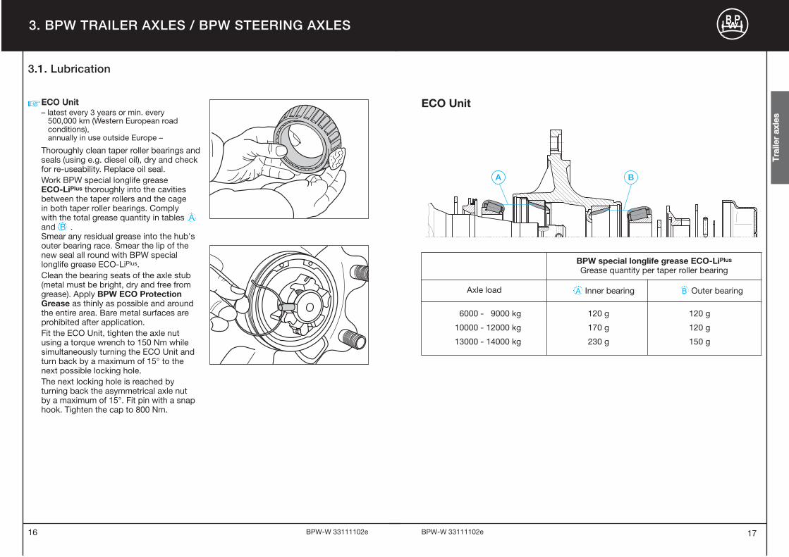
EECCOO UUnniitt– latest every 3 years or min. every
500,000 km (Western European road conditions), annually in use outside Europe –
Thoroughly clean taper roller bearings andseals (using e.g. diesel oil), dry and checkfor re�useability. Replace oil seal.Work BPW special longlife grease ECO�LiPlus thoroughly into the cavitiesbetween the taper rollers and the cage in both taper roller bearings. Comply with the total grease quantity in tables Aand B . Smear any residual grease into the hub'souter bearing race. Smear the lip of thenew seal all round with BPW speciallonglife grease ECO�LiPlus.Clean the bearing seats of the axle stub(metal must be bright, dry and free fromgrease). Apply BPW ECO ProtectionGrease as thinly as possible and aroundthe entire area. Bare metal surfaces areprohibited after application. Fit the ECO Unit, tighten the axle nutusing a torque wrench to 150 Nm whilesimultaneously turning the ECO Unit andturn back by a maximum of 15° to thenext possible locking hole. The next locking hole is reached byturning back the asymmetrical axle nut by a maximum of 15°. Fit pin with a snaphook. Tighten the cap to 800 Nm.
�
TTrraa
iilleerr
aaxxllee
ss
BPW special longlife grease ECO�LiPlus
Grease quantity per taper roller bearing
Axle load A Inner bearing B Outer bearing
6000 � 9000 kg
10000 � 12000 kg
13000 � 14000 kg
120 g
170 g
230 g
120 g
120 g
150 g
ECO Unit
3.1. Lubrication
1918
3. BPW TRAILER AXLES / BPW STEERING AXLES
BPW�W 33111102e BPW�W 33111102e
TTrraa
iilleerr
aaxxllee
ss
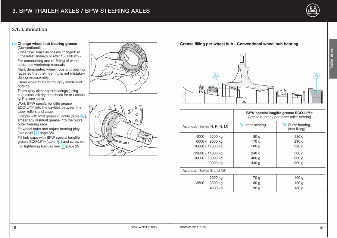
CChhaannggee wwhheeeell hhuubb bbeeaarriinngg ggrreeaassee(Conventional)– whenever brake linings are changed: at
the latest annually or after 150,000 km –For demounting and re�fitting of wheelhubs, see workshop manuals. Mark demounted wheel hubs and bearingraces so that their identity is not mistakenduring re�assembly. Clean wheel hubs thoroughly inside andoutside. Thoroughly clean taper bearings (using e. g. diesel oil) dry and check for re�useabili�ty. Replace seals.Work BPW special longlife grease ECO�LiPlus into the cavities between thetaper rollers and cage. Comply with total grease quantity (table A ),smear any residual grease into the hub’souter bearing race.Fit wheel hubs and adjust bearing play(see point 7 page 35).Fill hub caps with BPW special longlifegrease ECO�LiPlus (table B ) and screw on.For tightening torques see 5 page 29.
�
BPW special longlife grease ECO�LiPlus
Grease quantity per taper roller bearing
Axle load (Series H, K, N, M) A Inner bearing B Outer bearing (cap filling)
4000 � 5500 kg6000 � 9000 kg
10000 � 12000 kg
13000 � 14000 kg16000 � 18000 kg
20000 kg
80 g170 g180 g
240 g400 g440 g
130 g290 g320 g
500 g800 g900 g
Axle load (Series E and NE)
3000 kg3500 � 3800 kg
4500 kg
70 g80 g90 g
100 g120 g180 g
Grease filling per wheel hub � Conventional wheel hub bearing
3.1. Lubrication

21BPW�W 33111102e20
3. BPW TRAILER AXLES / STEERING AXLES
BPW�W 33111102e
3.2. Maintenance Work and Visual Inspection
3.2.1. General
In order to distribute the braking effort evenly to all the brakes in the unit, adjustment mustalways be carried out according to the vehicle manufacturer's specifications, or after5,000 km. Tractor units with EBS cannot have their brakes adjusted in the normal manner.As a result, the trailer or semi�trailer merely has to be checked for compliance with the ECtolerance bands. Always check the tractor vehicle if the trailer is in the EC band despite pre�mature brake pad wear. The EBS parameters in the tractor unit must be modified in order toimprove compatibility, see ECE R 13 in this connection. Failure to do so will invalidate thewarranty (see warranty documents).
Other possible solutions to premature brake pad wear:
� Prescribed maintenance work must be performed at regular intervals.
� Use the retarder or engine brake to adjust the vehicle’s speed.
� Think ahead when driving.
� Drop down to a lower gear in good time.
� BPW Disc Protector (cover plates for brake discs).
Even at high temperatures, disc brakes display stable braking properties and a high level ofsafety. Excessive temperatures do not make themselves apparent through brake fading andshould be avoided. This effect leads to increased wear when used under these conditions.
TTrraa
iilleerr
aaxxllee
ss

5 7
5 7
1
1
3
7 23 4 615
3
2 6
4
64 23
2322
3. BPW TRAILER AXLES / BPW STEERING AXLES
BPW�W 33111102e BPW�W 33111102e
SSeerriieess HH,, KKHH,, NNHH
SSeerriieess LLLL
Maintenance work � Drum brakes1 Check wheel nuts for tightness. 1
2 With manual slack adjusters, check brake play, 2adjust if necessary to 10 � 12% of the connected brake lever length and activate by hand or with 0.5 � 0.8 bar. (Not applicable in the case of automatic slack adjusters.)
– Check the tyres for uneven wear, adjust the inflation –pressure if necessary, according to the manufacturer's specifications.
3 Check brake lining thickness is at least 5 mm. (Cam 3brake N 3006 min. 2.5 mm residual lining thickness.)
4 Check brake drum for cracks and check the internal 4diameter.
5 Check caps for firm seating (not necessary with 5ECO Plus 2 and ECOPlus axles).
6 Check operation of automatic slack adjusters. 6 6
° Visual inspection of all component parts and welding ° °seams for damage and wear.
7 Check wheel hub bearing play, adjust if necessary.� ECO Plus 2 and ECOPlus Unit 7� ECO Unit, conventional bearing 7
1) After the first run under load conditions, likewise after each wheel change.2) Under extreme conditions, increase frequency (e.g. construction sites and poor roads).3) For use outside Europe.
Note: Components that have damages due to improper mounting are to be exchanged after a review by a BPW Service Centre.
Overview
For detailed description, see pages 24 � 35Disc brakes, see pages 36 � 58Air suspension, see pages 60 � 74Suspension, see pages 76 � 85 E
very
26
wee
ks 2)
At
ever
y b
rake
lini
ngre
pla
cem
ent,
late
st a
nnua
lly 2)
1)
TTrraa
iilleerr
aaxxllee
ss
Eve
ry 1
2 w
eeks
Initi
ally
Eve
ry 1
to
3 w
eeks
SSeerriieess NNEE,, NNMM,, NNRR,, MM
3)
3)
3.2. Maintenance Work and Visual Inspection3.2.2. Drum brakes
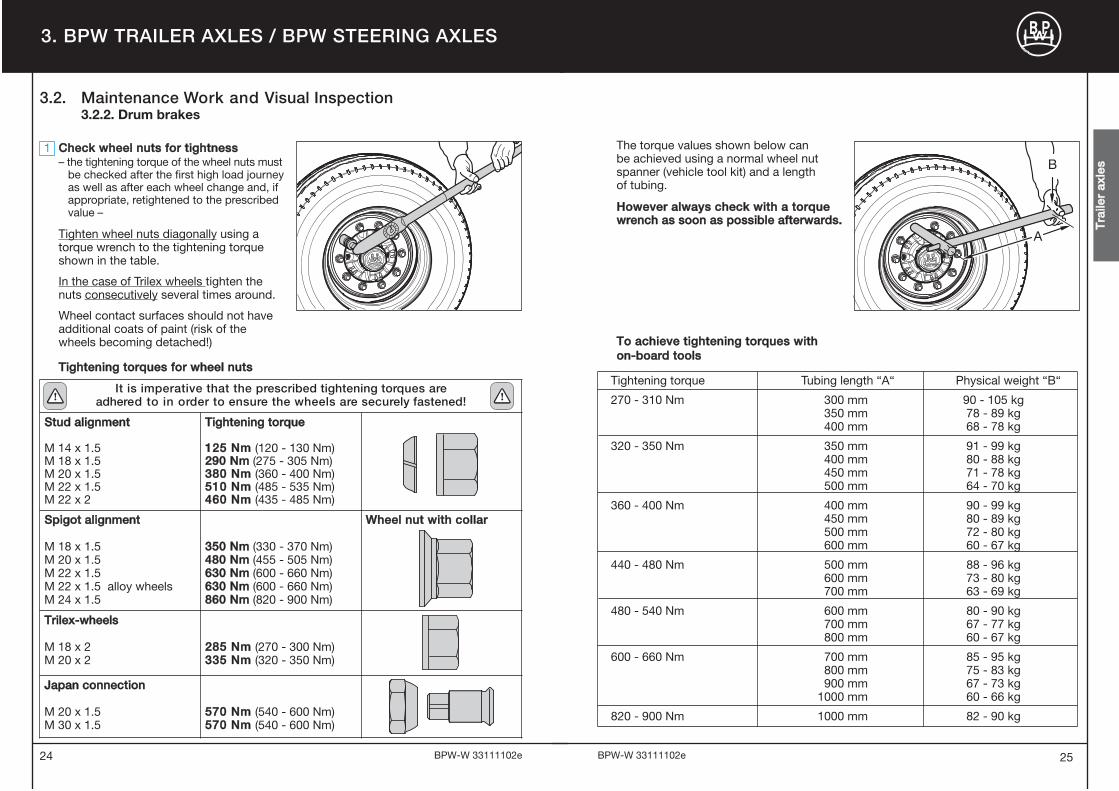
The torque values shown below can be achieved using a normal wheel nutspanner (vehicle tool kit) and a length of tubing.
HHoowweevveerr aallwwaayyss cchheecckk wwiitthh aa ttoorrqquueewwrreenncchh aass ssoooonn aass ppoossssiibbllee aafftteerrwwaarrddss..
25
1 CChheecckk wwhheeeell nnuuttss ffoorr ttiigghhttnneessss– the tightening torque of the wheel nuts must
be checked after the first high load journey as well as after each wheel change and, if appropriate, retightened to the prescribed value –
Tighten wheel nuts diagonally using atorque wrench to the tightening torqueshown in the table.
In the case of Trilex wheels tighten thenuts consecutively several times around.
Wheel contact surfaces should not haveadditional coats of paint (risk of thewheels becoming detached!)
24 BPW�W 33111102e BPW�W 33111102e
3. BPW TRAILER AXLES / BPW STEERING AXLES
A
B
Tightening torque Tubing length “A“ Physical weight “B“
270 � 310 Nm 300 mm 90 � 105 kg350 mm 78 � 89 kg400 mm 68 � 78 kg
320 � 350 Nm 350 mm 91 � 99 kg400 mm 80 � 88 kg450 mm 71 � 78 kg500 mm 64 � 70 kg
360 � 400 Nm 400 mm 90 � 99 kg450 mm 80 � 89 kg500 mm 72 � 80 kg600 mm 60 � 67 kg
440 � 480 Nm 500 mm 88 � 96 kg600 mm 73 � 80 kg700 mm 63 � 69 kg
480 � 540 Nm 600 mm 80 � 90 kg700 mm 67 � 77 kg800 mm 60 � 67 kg
600 � 660 Nm 700 mm 85 � 95 kg800 mm 75 � 83 kg900 mm 67 � 73 kg
1000 mm 60 � 66 kg
820 � 900 Nm 1000 mm 82 � 90 kg
TTrraa
iilleerr
aaxxllee
ss
TToo aacchhiieevvee ttiigghhtteenniinngg ttoorrqquueess wwiitthh oonn--bbooaarrdd ttoooollss
It is imperative that the prescribed tightening torques are adhered to in order to ensure the wheels are securely fastened!
SSttuudd aalliiggnnmmeenntt
M 14 x 1.5M 18 x 1.5M 20 x 1.5M 22 x 1.5M 22 x 2
TTiigghhtteenniinngg ttoorrqquuee
112255 NNmm (120 � 130 Nm)229900 NNmm (275 � 305 Nm)338800 NNmm (360 � 400 Nm)551100 NNmm (485 � 535 Nm)446600 NNmm (435 � 485 Nm)
SSppiiggoott aalliiggnnmmeenntt
M 18 x 1.5M 20 x 1.5M 22 x 1.5M 22 x 1.5 alloy wheelsM 24 x 1.5
335500 NNmm (330 � 370 Nm)448800 NNmm (455 � 505 Nm)663300 NNmm (600 � 660 Nm)663300 NNmm (600 � 660 Nm)886600 NNmm (820 � 900 Nm)
WWhheeeell nnuutt wwiitthh ccoollllaarr
TTrriilleexx--wwhheeeellss
M 18 x 2M 20 x 2
228855 NNmm (270 � 300 Nm)333355 NNmm (320 � 350 Nm)
JJaappaann ccoonnnneeccttiioonn
M 20 x 1.5M 30 x 1.5
557700 NNmm (540 � 600 Nm)557700 NNmm (540 � 600 Nm)
TTiigghhtteenniinngg ttoorrqquueess ffoorr wwhheeeell nnuuttss
3.2. Maintenance Work and Visual Inspection3.2.2. Drum brakes

2726
3. BPW TRAILER AXLES / BPW STEERING AXLES
BPW�W 33111102e BPW�W 33111102e
TTrraa
iilleerr
aaxxllee
ss
2 CChheecckk aanndd aaddjjuusstt wwhheeeell bbrraakkee ppllaayy wwiitthh mmaannuuaall ssllaacckk aaddjjuusstteerrss– frequent checks are necessary –– depending upon application
every 1 to 3 weeks –
Actuate slack adjusters by hand, pullingagainst the return spring. If there is morethan 35 mm of play, the slack adjustermust be reset. This can be done byadjusting the nut on the slack adjuster as shown.Adjust the play “a” to 10 �12% of theconnected brake lever length “B”, e.g.lever length 150 mm = 15 � 18 mm ofplay.Automatic slack adjusters make thisadjustment automatically whenever thecamshaft is rotated by more than 17.5°.
– CChheecckk tthhee ttyyrreess ffoorr uunneevveenn wweeaarr,, aaddjjuusstt tthhee iinnffllaattiioonn pprreessssuurree iiff nneecceessssaarryy aaccccoorrddiinngg ttoo tthhee mmaannuu--ffaaccttuurreerr''ss ssppeecciiffiiccaattiioonnss..– quarterly –
min. 5 mm
3 CChheecckk bbrraakkee lliinniinngg tthhiicckknneessss– quarterly –
Open inspection hole by folding back therubber flap (not required with ECO Drumbrakes). The brake lining should bereplaced at a residual lining thickness of 5 mm (check with slide gauge) or onreaching the bottom of the indicatormachined into the edge of the lining. Re�insert the rubber flap.
If brake lining wear indicators are fitted to the slack adjusters, the minimumthickness of the brake linings is indicatedby the horizontal position of the lever(when the brake is released).
The Brake Monitor displays the “Service”signal when the wear sensor for drumbrakes is installed. There is no warningfunction.
In certain cases the slack adjusters may not be fitted in the normal (i.e. vertical)position. In such instances, the positionof the wear indicator will also be different.Linings should be changed when thewear indicator is approximately at rightangles to the brake lever.
33
ECO Drum ECO Drum / BPW 95
3.2. Maintenance Work and Visual Inspection3.2.2. Drum brakes

29BPW�W 33111102e28
3. BPW TRAILER AXLES / BPW STEERING AXLES
BPW�W 33111102e
5 CChheecckk ccaappss ffoorr ffiirrmm sseeaattiinngg– every 6 months – (not necessary with ECO Plus 2 and ECOPlus axles)
Check caps for tightness using a torquewrench or power tool.Tightening torques:
Cap for ECO and ECOPlus Unit 6 � 12 t 800 NmSteel cap 6 � 12 t 500 Nm
14 t 800 NmAlloy cap 6 � 12 t 350 Nm
Steel cap 5.5 t 500 NmSteel cap 6 � 16 t 700 NmAlloy cap 5.5 � 12 t 350 Nm
In an emergency the caps can be tightened using a normal cap spanner(vehicle tool kit) by striking the latter with a hammer, or also with the aid of a pieceof tubing inserted into the spanner. Caps with integrated hubodometers mustbe fitted and dismantled using only torquecontrolled (not impact!) air guns or manu�ally with a torque wrench.Tighten to the correct tightening torqueas soon as possible.
4 CChheecckk tthhee bbrraakkee ddrruumm ffoorr ccrraacckkss aanndd tthhee iinntteerrnnaall ddiiaammeetteerr– quarterly –Check the condition of the brake drumand that there is adequate remainingthickness. If the wear is approaching the wear edge,measure the brake drum and renew it ifthe maximum permitted amount of wearhas been reached.
ECO DrumMax. amounts of wear, measured at theposition with the greatest wear:
Brake Brake shoewidth(mm)
Ø Max. amount ofwear (mm)
Ø Skimmingsize (mm)
SN 420 120 / 160 424 423
SN 420180 / 200 / 220
425.5 424
SN 360 160 / 200 364 363
SN 300100 / 150 / 200
304 303
FL 300 80 303 302
Wearing edgeof brake lining
Wearing edgeof brake drumBrake drum
Brake lining
Caps on ECO Plus 2 axles are providedwith a bayonet fitting. Check for firmseating.Position 1: Hub cap seated loosely on the
Unit.Position 2: Hub cap seated firmly on the
Unit.
�Position 1 Position 2
TTrraa
iilleerr
aaxxllee
ss
BPW 95
3.2. Maintenance Work and Visual Inspection3.2.2. Drum brakes

3130
3. BPW TRAILER AXLES / BPW STEERING AXLES
BPW�W 33111102e BPW�W 33111102e
TTrraa
iilleerr
aaxxllee
ss
6 CChheecckk ooppeerraattiioonn ooff tthhee aauuttoommaattiicc ssllaacckk aaddjjuusstteerr– every 6 months –– quarterly in use outside Europe (e.g. within
the scope of the statutory checks) –
Prevent the vehicle from rolling away.Release the service brakes and thehandbrake.Free play check:Operate the slack adjuster by hand or with0.8 bar. In this case, the free play „a“ cor�responds to 10 � 15 % of the connectedbrake lever length „B“, e.g. brake leverlength 150 mm = free play 15 � 22 mm.
Check the adjustment if the free play is notwithin tolerance:Remove rubber seal cap. Turn back adjustment bolt, keep clutch sleeve pres�sed down, by approx. 3/4 of a turn in a counterclockwise direction using a ring spanner. A play of at least 50 mmwith a lever length of 150 mm must beavailable. Actuate the brake lever several times by hand. When this is done automaticadjustment must take place smoothly. Engagement of the clutch coupling isaudible and on the return stroke theadjustment bolt turns slightly in a clockwise direction. Grease with ECO�LiPlus, see also 3 on page 9. Fit seal cap. Adjust the brake, see relevant workshopmanual.
° VViissuuaall iinnssppeeccttiioonn– every 6 months –– quarterly in use outside Europe –
Check all components and welding seamsfor damage and wear.
7 CChheecckk wwhheeeell hhuubb bbeeaarriinngg ppllaayy– ECO Plus 2 and ECOPlus Unit at every
brake lining replacement, latest annually –– ECO Unit und conventional hub
bearing every 6 months –
Prevent the vehicle from rolling away.In order to check the wheel hub bearingplay, lift the axle until the wheels are offthe ground. Release the brake.Apply a lever between the tyre and theground and check the play.
If bearing play is detected �ECO Plus 2 Unit:Adjust the bearing play1. Unscrew the cap with a 120 mm
hub cap spanner. Undo the cap by turning it anti�clockwise by approx. 30° from position 1 to position 2.When turned further the hub cap lifts clearly away from the ECO Unit and can be removed by pulling it away.
Important!Do not use an impact driver -bayonet lock.
2. Remove the hooked spring ring and retaining key from the axle bolt. Position 1 Position 2
B
a
3.2. Maintenance Work and Visual Inspection3.2.2. Drum brakes

33BPW�W 33111102e32
3. BPW TRAILER AXLES / BPW STEERING AXLES
BPW�W 33111102e
If bearing play is detected �ECOPlus Unit:Adjust the bearing play1. Unscrew the cap. 2. Remove the hooked spring ring with
a wedge from the axle nut.3. Use a spanner to tighten the axle nut
whilst at the same time turning the ECO Unit, until the axle nut torque limiter operates.
Important!Do not use an impact driver.
4. Fit the retaining key in the groove between the axle stub and the nut (do not reset the axle nut).
5. For production date April 2000 onwards,insert the hooked spring ring behind the edge of the axle nut or, up to March 2000, into the thread on the axle stub.
6. Tighten the cap to 800 Nm.
TTrraa
iilleerr
aaxxllee
ss
3. Tighten the axle bolt at the same time as turning the ECO Unit with a 46 mm hexagon spanner until the gearing slips over the axle bolt.
Important!Do not use an impact driver.
Position 1 Position 2
7. Apply a thin layer of BPW ECO�LiPlus
special long�life grease to the hubcap in the area of the O�ring contact sur�face and the bayonet fitting.
8. Screw on the cap with a 120 mm cap spanner.
Important!Do not use an impact driver -bayonet lock.
Push on the hubcap, see position 1.Press on the hubcap and turn it by approx. 30° in a clockwise direction to lock it in place. A tight seat is provided when position 2 is reached.
4. Insert the retaining key into the recess in the axle bolt and the gearing of the toothed lock washer (arrow). (Do not turn back the axle bolt.)
5. Insert the hooked spring ring into the groove of the hexagon profile of the axle bolt. Make sure that the clasped spring ring assembly is correctly seatedin the annular groove of the axle bolt.
6. Insert a new O�ring into the groove in the wheel hub.
3.2. Maintenance Work and Visual Inspection3.2.2. Drum brakes

3534
3. BPW TRAILER AXLES / BPW STEERING AXLES
BPW�W 33111102e BPW�W 33111102e
If bearing play is detected �conventional hub bearing:Adjust the bearing play1. Unscrew the cap. 2. Remove the split pin from the axle nut.3. Tighten using a torque wrench whilst
simultaneously turning the wheel.Tightening torques:Up to an axle load of 5.5 tons = 100 Nm,From 6 to 14 tons axle load = 150 Nm,From 16 to 30 tons axle load = 350 Nm.� If a normal axle nut spanner is used (vehicle tool kit), tighten the axle nut until the wheel bearing race drags slightly.
4. Turn back the axle nut to the next available split pin hole. Should they already be in line turn back to the next hole (30° at the maximum). (Does not apply to the ECO Plus 2, ECOPlus
and ECO Unit.)5. Insert the split pin and bend upwards
slightly.6. Refill the cap as required with
BPW special longlife grease ECO�LiPlus
and replace. For tightening torques see point 5 on page 29.
TTrraa
iilleerr
aaxxllee
ss
If bearing play is detected �ECO Unit:Adjust the bearing play1. Unscrew the cap.2. Loosen axle nut.3. Tighten axle nut with torque wrench
while simultaneously turning the ECO Unit with a tightening moment of 150 Nm.� If a normal axle nut spanner is used (vehicle tool kit), tighten the axle nut until the ECO Unit drags slightly (auxiliary solution).
4. Turn back axle nut to the next locking position (max. 15°). The asymmetrical cap of the axle nut enables the next locking position to be reached after turning back max. 15°.
5. Insert bolt and locking ring. 6. Screw on cap.
Tightening torque:Steel / cast cap 800 Nm Aluminium cap 350 Nm
3.2. Maintenance Work and Visual Inspection3.2.2. Drum brakes

37BPW�W 33111102e36
3. BPW TRAILER AXLES / BPW STEERING AXLES
BPW�W 33111102e
Maintenance work � Disc brakesBrake type: TSB 3709, TSB 4309, TSB 4312
1 Check wheel nuts for tightness. 1 2)
2 Check brake pad thickness. 2
� Visual check, check all components and welding seams –for damage, wear and corrosion.
3 Check brake disc thickness and visually check for 3 3)
3cracks.
4 Check caliper guide system. 4 3)
4
5 Check coarse dirt seals at the pressure plates. 5 3)
5
6 Check the bearing play of the ECO Unit, adjust 6if necessary.
1) Under extreme conditions, increase frequency (e.g. Off�Road, heavy�duty braking work).2) After the first run under load conditions and likewise after each wheel change.3) For use outside Europe.
Note: Components that have damages due to improper mounting are to be exchanged after a review by a BPW Service Centre.
Overview
For detailed description, see pages 38 � 44Disc brakes type SB, see pages 46 � 58Air suspension, see pages 60 � 74Suspension, see pages 76 � 85
Initi
ally
Eve
ry 1
2 w
eeks
1)
Eve
ry 2
6 w
eeks
1)
At
ever
y b
rake
linin
g re
pla
cem
ent,
la
test
ann
ually
2
3
5 416SSeerriieess SSHH wwiitthh ddiisscc bbrraakkeess ttyyppee TTSSBB
SSeerriieess LLLL wwiitthh ddiisscc bbrraakkeess ttyyppee TTSSBB
TTrraa
iilleerr
aaxxllee
ss
3.2. Maintenance Work and Visual Inspection3.2.3. Disc brakes, brake types TSB 3709, TSB 4309, TSB 4312

39BPW�W 33111102e38
3. BPW TRAILER AXLES / BPW STEERING AXLES
BPW�W 33111102e
Wheel nuts for:
Stud alignment Spigot alignment
1 CChheecckk wwhheeeell nnuuttss ffoorr ttiigghhttnneessss– the tightening torque of the wheel nuts must
be checked after the first high load journey as well as after each wheel change and, if appropriate, retightened to the prescribed value –
Tighten wheel nuts diagonally using atorque wrench to the correct tighteningtorque.
It is imperative that the prescribedtightening torques are adhered toin order to ensure the wheels aresecurely fastened!
Tightening torques for wheel nuts M 22 x 1.5:Stud alignment:
510 Nm (485 � 535 Nm)Spigot alignment:
630 Nm (600 � 660 Nm)
Warning: Do not exceed specified settings!Wheel contact surface should not haveadditional coats of paint (risk of the wheelsbecoming detached)!
TTrraa
iilleerr
aaxxllee
ss
3.2. Maintenance Work and Visual Inspection3.2.3. Disc brakes, brake types TSB 3709, TSB 4309, TSB 4312
2 CChheecckk bbrraakkee ppaadd tthhiicckknneessss– quarterly –
The brake pad thickness must be checkedregularly, e.g. during the tyre inflationpressure check. The intervals must not bemore than 3 months.
The brake pad thickness can be checkedwhere the brake caliper interfaces with thewelded anchor plate with the wheelsmounted (approximate wear indicator).
Dimension x (distance between brakecaliper and brake anchor plate):9 mm => when newTSB 3709 / TSB 430930 mm => max. permissible brake
pad wear, 21 mm34 mm => max. permissible wear for
brake pad and brake discTSB 431228 mm => max. permissible brake
pad wear, 19 mm32 mm => max. permissible wear for
brake pad and brake disc
The brake pads must be removed toinspect them more closely � see relevantworkshop manual.Heat affected, glazed over, or oily brakepads must be replaced immediately.The remaining brake pad thickness mustnot be less than 2 mm (use a calipergauge for this).Hairline cracks at the edges are permis�sible; replacement is required if moresizable surface cracks are present.
Lining anchor plate
Brake lining
Total brakelining thickness
2 mmBrake liningthickness
30 mm
X X
New condition Check required
–– VViissuuaall iinnssppeeccttiioonn– every six months –
Check all components and weldingseams for damage, wear and corrosion.

41BPW�W 33111102e40
3. BPW TRAILER AXLES / BPW STEERING AXLES
BPW�W 33111102e
TTrraa
iilleerr
aaxxllee
ss
max. 0.75 x a
max. 1.5 mm
aA
D C
B
3 BBrraakkee ddiissccCheck the condition of the brake disc– every 6 months when used within Europe,
quarterly when used outside Europe – Sections A � D (see fig.) show the possibleconditions of the disc surface:AA:: Network�type tears = permissibleBB:: Radial cracks
up to max. 1.5 mmwidth and depth = permissible
CC:: Uneven disc surface lessthan 1.5 mm = permissible
DD:: Continuous cracks = not permissible
Technical details:• Disc thickness, new = 45 mm• Minimum permissible
disc thickness = 37 mm(Use a caliper gauge where the pads make contact)
In the case of surface conditions A � C, the brake disc can be used until the minimum permissible disc thickness has been reached.
IMPORTANT!To prevent damage to the brake discs, the brake pads should be replaced when their thickness (excluding backing plate) is 2 mm or less.Brake discs should always be replaced inpairs. The brake pads should also bereplaced when new brake discs are fitted.If this instruction is not adhered to, there is a danger that braking performance could be seriously reduced.
�
30 mm
2 mm
45 mm37 mm Wear edge
4 mm
3.2. Maintenance Work and Visual Inspection3.2.3. Disc brakes, brake types TSB 3709, TSB 4309, TSB 4312
010
20 30
4050
60
7 080
90
1
32
4 CChheecckkiinngg tthhee bbrraakkee ccaalliippeerr gguuiiddee ssyysstteemm(check play and adjustment)– every 6 months when used within Europe,
quarterly when used outside Europe – (e.g. within the scope of the statutorychecks)
Prevent the vehicle from rolling away.Release the service and parking brakes. The brake cylinder and fasteners for thebrake pads can remain fitted.Forcefully push the sliding caliper in theaxle direction. The caliper must moveapproximately 0.7 to 1.3 mm (play). If play is not within this tolerance, thebrake caliper guide must be checked andreadjusted.
For close inspection of play with wheels mounted:Use a dial gauge to determine the play. To this end, attach a dial gauge holder tothe axle housing and position the buttonon the outside of the screw plug (1) or onthe brake cylinder.
For close inspection of play with wheels removed:Check the play using two feeler gauges. Forcefully push the sliding caliper towardthe centre of the axle and insert thegauges between the pressure plates (2)and pad backing plate (3).If play is not within the tolerance required, adjustment must be carried out and thebrake caliper guide checked.

43BPW�W 33111102e42
3. BPW TRAILER AXLES / BPW STEERING AXLES
BPW�W 33111102e
TTrraa
iilleerr
aaxxllee
ss
4
4
1
1
Set play and check adjustment1. Remove the plug.2. Using a torx wrench (T25), depress the
return spring and turn clockwise until it „clicks“ 2 times.
3. Actuate the brake 5 to 10 times with a force of approximately 2 bar.
4. Forcefully push the sliding caliper in the axle direction. The play exhibited at this time must be between 0.7 and 1.3 mm. Adjustment is correct if play is within this tolerance.
5. Reinsert the plug.
Check brake caliper guide:The brake caliper guide must be checkedif the play was not adjusted properly. The guide bushings are sealed by thebellows (4) and the screw plug (1).Inspect the bellows and sealing plugs forcracks, damage, and proper seating andreplace if necessary. Sealing plugs thathave been removed must be replaced,not re�used.
See workshop manual ECO Disc for infor�mation on how to repair the brake caliperguide.
3.2. Maintenance Work and Visual Inspection3.2.3. Disc brakes, brake types TSB 3709, TSB 4309, TSB 4312
> 30 mm5 CChheecckk ccooaarrssee ddiirrtt sseeaallss aatt tthhee ttaappppeettss– at every brake lining replacement,
latest annually in Europe –– every six months in use outside Europe –
Prevent the vehicle from rolling away.Release the service and parking brakes.See workshop manual ECO Disc for infor�mation on how to remove the brake pads.The service brake and spring actuatormust be released.Unscrew the tappets (362) beyond theadjuster (min. 30 mm) until the coarse dirtseals (365) are plainly visible.Ensure proper seating. (Visual inspection, see detail extract)
Check the dust cover of the brake calliperin the area between the coarse dirt seals(365, arrows) for deformation. If deforma�tion is detected, the brake calliper requireschanging!
Note: Penetrating dirt and damp cause corrosionand affect the operation of the clampingmechanism and adjustment.
The bellows must be replaced if thermaloverloading was detected.Only new parts may be used.The adjustment device must be checkedfor corrosion and ease of movementbefore the new parts are installed.See workshop manual ECO Disc forinformation on how to replace the bel�lows.
Check the brake calliper bearing play:The bearing play of the brake calliper canbe established using a dial gauge. Attachthe dial gauge holder to the axle beam andposition the gauge, facing the long locatingbearing, on the lower edge of the cylinderflange.Press the brake calliper on the brake cylin�der vertically downwards to its installationdiagram and set the dial gauge to "zero".Press the brake calliper upwards and readthe bearing play on the dial gauge.If a brake calliper bearing play exceeds 1.5 mm, the brake calliper bearing must be replaced.

45BPW�W 33111102e44
3. BPW TRAILER AXLES / BPW STEERING AXLES
BPW�W 33111102e
TTrraa
iilleerr
aaxxllee
ss
6 CChheecckk tthhee bbeeaarriinngg ppllaayy ooff tthhee EECCOO UUnniitt– at every brake lining replacement,
latest annually –
Prevent the vehicle from rolling away.In order to check the bearing play of theECO Unit, lift the axle until the wheels areoff the ground. Release the brake.Apply a lever between the tyre and theground and check the play.
The bearing play must be reset if thebearing play can be felt. See instructions on setting bearings forECO Plus 2 and ECOPlus, pages 31 to 33.
3.2. Maintenance Work and Visual Inspection3.2.3. Disc brakes, brake types TSB 3709, TSB 4309, TSB 4312

4746
3. BPW TRAILER AXLES / BPW STEERING AXLES
BPW�W 33111102e BPW�W 33111102e
Maintenance work � Disc brakeBrake type: SB 3308, SB 3745, SB 4309, SB 4345
1 Check wheel nuts for firm seating. 1 1)
2 Check brake pad thickness. 2
– Check the tyres for uneven wear, adjust the inflation –pressure if necessary according to the manufacturer's specifications.
° Visual check of all components and welding seams °for damage, wear and corrosion.
3 Check brake disc thickness and visually check for cracks. 3 3)
3
4 Check brake adjustment. 4 3)
4
5 Check caliper guide system. 5 3)
5
6 Check bellows on the guide pins.� ECO Plus 2 and ECOPlus axles 6
3)6
� ECO axles and axles with conventional hub bearing 6
7 Check caliper unit.� ECO Plus 2 and ECOPlus axles 7
3)7
� ECO axles and axles with conventional hub bearing 7
8 Check wheel hub bearing play, adjust if necessary.� ECO Plus 2 and ECOPlus Unit 8� ECO Unit and conventional hub bearing 8
9 Check caps for tightness. 9(not necessary with ECO Plus 2 and ECOPlus axles)
1) After the first run under load conditions, likewise after each wheel change.2) Under extreme conditions, increase frequency (eg. construction sites and poor roads).3) For use outside Europe.
Note: Components that have damages due to improper mounting are to be exchanged after a review by a BPW Service Centre.
Overview
For detailed description, see pages 48 � 58Disc brakes type TSB, see pages 36 � 44Air suspension, see pages 60 � 74Suspension, see pages 76 � 85 E
very
26
wee
ks 2)
At e
very
bra
ke li
ning
rep
lace
men
t,la
test
ann
ually
2)
Eve
ry 1
2 w
eeks
Initi
ally
TTrraa
iilleerr
aaxxllee
ss8 19 2 3 6 4 75
5
SSeerriieess SSHH // SSKKHH wwiitthh ddiisscc bbrraakkeess ttyyppee SSBB
SSeerriieess SSHH....LLLL // SSKKHH....LLLL wwiitthh ddiisscc bbrraakkeess ttyyppee SSBB
SSeerriieess SSNNRR wwiitthh ddiisscc bbrraakkeess ttyyppee SSBB
3.2. Maintenance Work and Visual Inspection3.2.4. Disc brakes, brake types SB 3308, SB 3745, SB 4309, SB 4345

4948
3. BPW TRAILER AXLES / BPW STEERING AXLES
BPW�W 33111102e BPW�W 33111102e
TTrraa
iilleerr
aaxxllee
ss
1 CChheecckk wwhheeeell nnuuttss ffoorr ttiigghhttnneessss– the tightening torque of the wheel nuts
must be checked after the first high load journey as well as after each wheel change and, if appropriate, retightened to the prescribed value –
Tighten wheel nuts diagonally using atorque wrench to the correct tighteningtorque.
It is imperative that the prescribedtightening torques are adhered toin order to ensure the wheels aresecurely fastened!
Tightening torques for wheel nuts M 18 x 1.5:Stud alignment:
229900 NNmm (275 � 305 Nm)Spigot alignment:
335500 NNmm (330 � 370 Nm)
M 22 x 1.5:Stud alignment:
551100 NNmm (485 � 535 Nm)Spigot alignment:
663300 NNmm (600 � 660 Nm)
Warning: Do not exceed specifiedsettings!Wheel contact surface should not haveadditional coats of paint (risk of the wheelsbecoming detached)!
Wheel nuts for:
Stud alignment Spigot alignment
3.2. Maintenance Work and Visual Inspection3.2.4. Disc brakes, brake types SB 3308, SB 3745, SB 4309, SB 4345
Lining anchor plate
Brake lining
Total brakelining thickness
2 mmBrake liningthickness
30 mm
21
3
2 CChheecckk bbrraakkee ppaadd tthhiicckknneessssSSBB 33774455 // SSBB 44330099 // SSBB 44334455– quarterly –
The brake pad thickness must be checkedregularly, e.g. during the tyre inflationpressure check. The intervals must not bemore than 3 months.The thickness of the remaining pad mustnot be less than 2 mm (check with slidegauge).
Sealed bearing:The sealed bearing has a ridged rubberseal which is fitted over the guide pin. Pad wear should be checked when thewear mark (transition point between theridged and smooth areas � see diagram) has moved to the end of the guide pin.
�
Open bearing:The thickness of the brake pad can be checked by the position of the brake caliper (1) in relation to the guide rod (2) (rough indication of wear).If the end of the guide sleeve (3) is levelwith the fixed guide rod, the pad thicknessmust be checked again after the wheelshave been removed.
� New condition Check brake padthickness
Check brake padthickness
Wear indicator Wear indicator
New condition

5150 BPW�W 33111102e BPW�W 33111102e
3. BPW TRAILER AXLES / BPW STEERING AXLES
TTrraa
iilleerr
aaxxllee
ss
CChheecckk bbrraakkee ppaadd tthhiicckknneessssSSBB 33330088– quarterly –
The brake pad thickness must be checkedregularly, e.g. during the tyre inflationpressure check. The intervals must not bemore than 3 months.The thickness of the remaining pad mustnot be less than 2 mm (check with slidegauge).
The brake pad thickness can be checkedwith the wheels attached by means of theposition of the brake caliper marking (P) in relation to the fixed brake carrier flange(R).On reaching the status as shown in theillustration below right, the brake padthickness and the brake disc must bechecked with the wheel removed.Replace the brake pads and/or brake discas necessary.
3.2. Maintenance Work and Visual Inspection3.2.4. Disc brakes, brake types SB 3308, SB 3745, SB 4309, SB 4345
max. 0.75 x a
max. 1.5 mm
aA
D C
B
3 BBrraakkee ddiissccCheck the condition of the brake disc– every 6 months –– quarterly in use outside Europe –Section A � D (see fig.) show the possibleconditions of the disc surface:AA:: Network�type tears = permissibleBB:: Radial cracks
up to max. 1.5 mmwidth and depth = permissible
CC:: Uneven disc surface lessthan 1.5 mm = permissible
DD:: Continuous cracks = not permissible
In the case of surface conditions AA -- CCthe brake disc can be used until theminimum permissible disc thickness hasbeen reached.
IMPORTANT!To prevent damage to the brake discs, the brake pads should be replaced when their thickness (excluding backing plate) is 2 mm or less.
If this instruction is not adhered to, there is a danger that braking performance could be seriously reduced.
�
° VViissuuaall iinnssppeeccttiioonn– every six months –
Check all components and welding seamsfor damage, wear and corrosion.
– CChheecckk tthhee ttyyrreess ffoorr uunneevveenn wweeaarr aanndd aaddjjuusstt tthhee iinnffllaattiioonn pprreessssuurree iiff nneecceessssaarryyaaccccoorrddiinngg ttoo tthhee mmaannuuffaaccttuurreerr’’ss ssppeecciiffiiccaattiioonnss– quarterly –

53BPW�W 33111102e52
3. BPW TRAILER AXLES / BPW STEERING AXLES
BPW�W 33111102e
30 mm
2 mm
45 mm37 mm Wear edge
4 mm
SB 3745 / SB 4309 / SB 4345Technical details:• Disc thickness, new = 45 mm• Minimum permissible
disc thickness = 37 mm(check with slide gauge)
SB 3308Technical details:A Disc thickness, new = 34 mm
minimum permissible disc thickness = 28 mm(check with slide gauge)
C1 Overall thickness of new brake pad = 27 mm
C2 Overall thickness of new brake pad = 34 mm
D1 Pad backing plate = 8 mmD2 Pad backing plate = 15 mmE Brake pad minimum
thickness = 2 mmF1 Brake pad minimum thick�
ness incl. pad backing plate = 10 mmF2 Brake pad minimum thick�
ness incl. pad backing plate = 17 mm
TTrraa
iilleerr
aaxxllee
ss
3.2. Maintenance Work and Visual Inspection3.2.4. Disc brakes, brake types SB 3308, SB 3745, SB 4309, SB 4345
4 CChheecckk aaddjjuussttmmeenntt– every 6 months –– quarterly in use outside Europe –
Prevent the vehicle from rolling away.Release the service brakes and the handbrake.
SB 3308Remove wheel. Remove pad retainer clip.Pull the brake caliper on its guide pins inthe direction of the outside of the vehicle.Using a suitable tool, press the outer brakepad in the direction of the pressure pad.Measure the gap between the backingplate and the inside of the caliper. Thismust be between 0.6 and 1.1 mm.
Important!If the air gap is too large, the braking effectmay fail.If the air gap is too small the brake mayoverheat and cause further damage.If the air gap is to big or too small, theadjustment must be checked as follows:
SB 3308 / SB 3745 / SB 4309 / SB 4345Remove cap.Place a ring spanner size 8 on the hex.profile of the adjuster, or a spanner size 10on the adjuster adapter. Turn anti�clockwiseuntil the ratchet clicks 3 or 4 times.
Important!If the version has an adjustment adapter,never turn without the adapter. Exceedingthe specified break�off torque of the adapterwill cause the adapter to break. Repeatwith a new adapter. Fit a new brake caliperif the adapter shears off again � this is anindication of internal damage.Do not use an open�ended spanner.Max. torque: approx. 25 Nm
�
�

5554
3. BPW TRAILER AXLES / BPW STEERING AXLES
BPW�W 33111102e BPW�W 33111102e
TTrraa
iilleerr
aaxxllee
ss
Apply brake 5 to 10 times (approximately 2 bar). If the adjustment is correct, thering spanner will turn back in a clockwisedirection (make sure the ring spanner canrotate freely).Note: As the cycle rate increases, themovement of the ring spanner, becomessmaller.If the ring spanner moves as described, the adjustment is OK.Remove ring spanner.Apply Renolit HLT2 to the cap and re�fit.For the version with the adapter, fit the lugon the cap pointing towards the axle beam.If the following faults occur:The adjuster, or the ring spanner:a) does not turn,b) turns only upon initial application,c) turns forward and back again upon
each application,the adjustment is not correct and the brake caliper must be replaced.
3.2. Maintenance Work and Visual Inspection3.2.4. Disc brakes, brake types SB 3308, SB 3745, SB 4309, SB 4345
5 CChheecckk tthhee bbrraakkee ccaalliippeerr gguuiiddee ssyysstteemm– every 6 months –(e.g. within the scope of the statutory checks)– quarterly in use outside Europe –
Prevent the vehicle from rolling away.Release the service brakes and the hand�brake.Apply considerable pressure to the slidingcaliper in the direction of the guide bear�ing. It should be possible to move it byabout 0.5 to 1 mm (play). Check the brakecaliper guide if this is not the case.
SB 3745 / SB 4309 / SB 4345The guide bush (1a) is sealed by thebellows (2) and the sheet metal cap (3) with the sealing ring (4).Parts (2) and (3) must not be split ordamaged in any way. Check for correctfitting.If the version has a guide sleeve (5), check it for damage and to make sure it is correctly seated.
SB 3308Ability of the caliper to slide to the fullextent of the caliper guides:Remove the brake pads. Fully retract thepressure pad (7) by turning the adjuster inan anti�clockwise direction, using anadapter.It must be possible to slide the brakecalliper (6) by hand over the entire distance of more than 20 mm on theguide pieces (8) and (9) as well as (10) and (11), without using any tools.Check caliper guide seals:The guide bushes (8) and (10) are sealedby means of the bellows pieces (12) and(13). These parts must not show anycracks or damage. Check that everythingis properly seated.
7 9 813
12
12
1011136
1a2 341
1 1a 5
57BPW�W 33111102e56
3. BPW TRAILER AXLES / BPW STEERING AXLES
BPW�W 33111102e
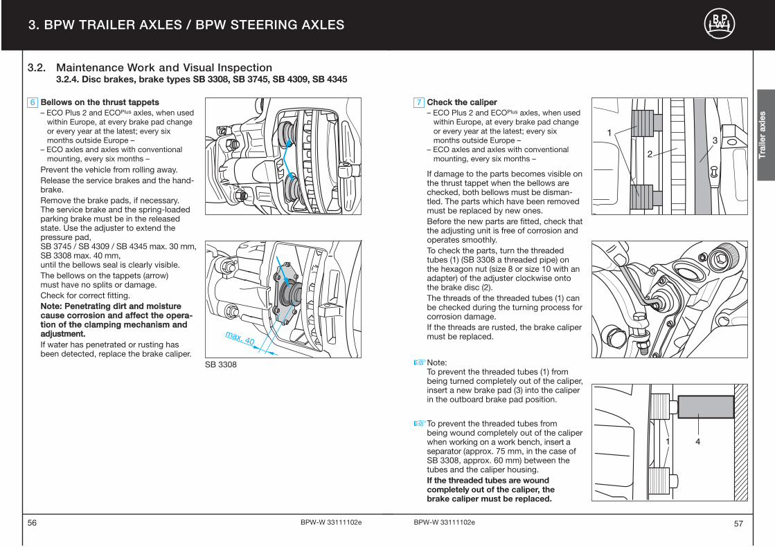
6 BBeelllloowwss oonn tthhee tthhrruusstt ttaappppeettss– ECO Plus 2 and ECOPlus axles, when used
within Europe, at every brake pad change or every year at the latest; every six months outside Europe –
– ECO axles and axles with conventional mounting, every six months –
Prevent the vehicle from rolling away.Release the service brakes and the hand�brake.Remove the brake pads, if necessary.The service brake and the spring�loadedparking brake must be in the releasedstate. Use the adjuster to extend thepressure pad,SB 3745 / SB 4309 / SB 4345 max. 30 mm,SB 3308 max. 40 mm,until the bellows seal is clearly visible.The bellows on the tappets (arrow) must have no splits or damage.Check for correct fitting.NNoottee:: PPeenneettrraattiinngg ddiirrtt aanndd mmooiissttuurreeccaauussee ccoorrrroossiioonn aanndd aaffffeecctt tthhee ooppeerraa--ttiioonn ooff tthhee ccllaammppiinngg mmeecchhaanniissmm aannddaaddjjuussttmmeenntt..If water has penetrated or rusting has been detected, replace the brake caliper.
TTrraa
iilleerr
aaxxllee
ss
max. 40
SB 3308
3.2. Maintenance Work and Visual Inspection3.2.4. Disc brakes, brake types SB 3308, SB 3745, SB 4309, SB 4345
13
2
7 CChheecckk tthhee ccaalliippeerr– ECO Plus 2 and ECOPlus axles, when used
within Europe, at every brake pad change or every year at the latest; every six months outside Europe –
– ECO axles and axles with conventional mounting, every six months –
If damage to the parts becomes visible onthe thrust tappet when the bellows arechecked, both bellows must be disman�tled. The parts which have been removedmust be replaced by new ones.Before the new parts are fitted, check thatthe adjusting unit is free of corrosion andoperates smoothly.To check the parts, turn the threadedtubes (1) (SB 3308 a threaded pipe) on the hexagon nut (size 8 or size 10 with anadapter) of the adjuster clockwise ontothe brake disc (2).The threads of the threaded tubes (1) can be checked during the turning process forcorrosion damage.If the threads are rusted, the brake calipermust be replaced.
Note:To prevent the threaded tubes (1) from being turned completely out of the caliper, insert a new brake pad (3) into the caliper in the outboard brake pad position.
To prevent the threaded tubes from being wound completely out of the caliper when working on a work bench, insert a separator (approx. 75 mm, in the case of SB 3308, approx. 60 mm) between the tubes and the caliper housing.If the threaded tubes are wound completely out of the caliper, the brake caliper must be replaced.
�
�

59
8 CChheecckk wwhheeeell hhuubb bbeeaarriinngg ppllaayy– ECO Plus 2 and ECOPlus Unit at every brake
pad change, however at least once a year –– ECO Unit and conventional hub bearing
every six months –
To check the wheel hub bearing play, raisethe axle until the tyres are free. Releasebrake. Position lever between tyre andground, and check play.If you can feel play in the bearing, adjust thebearing play as described on pages 31 � 35.
58 BPW�W 33111102e BPW�W 33111102e
3. BPW TRAILER AXLES / BPW STEERING AXLES
TTrraa
iilleerr
aaxxllee
ss
9 CChheecckk ccaappss ffoorr ttiigghhttnneessss(not necessary with ECO Plus 2 and ECOPlus
axles)– every 6 months and/ or as part of any
other service inspection –
Check caps for tightness using a torquewrench or power tool. Tightening torques:Steel cap 5.5 t M = 500 Nm
6 � 12 t M = 800 NmAlloy cap M = 350 NmIn an emergency the caps can be tight�ened using a normal cap spanner (vehicle tool kit) by striking the latter witha hammer, or also with the aid of a pieceof tubing, inserted into the spanner.Caps with integrated hubodometers mustbe fitted and dismantled using onlytorque controlled (not impact!) airguns or manually with a torque wrench.Tighten to the correct tighteningtorque as soon as possible.
Position 1 Position 2
Caps on ECO Plus 2 axles are providedwith a bayonet fitting. Check for firmseating.Position 1: Hub cap seated loosely on the
Unit.Position 2: Hub cap seated firmly on the
Unit.
�
3.2. Maintenance Work and Visual Inspection3.2.4. Disc brakes, brake types SB 3308, SB 3745, SB 4309, SB 4345

60 61BPW�W 33111102e BPW�W 33111102e
Air
sus
pen
sio
n
4. BPW AIR SUSPENSION
3
245
5
5 13
3 3
5
5
SSeerriieess AALLOO//SSLLOO SSeerriieess AALLOO//SSLLOO wwiitthh ttwwoo--ssiiddeedd aaxxllee lliifftt
SSeerriieess AALLMM//SSLLMM SSeerriieess AALLMM//SSLLMM wwiitthh bboolltteedd--oonnwwiitthh KKoommbbii--AAiirr BBaagg IIII aaiirr ssuussppeennssiioonn hhaannggeerr bbrraacckkeett
SSeerriieess AALLUU//SSLLUU wwiitthh SSeerriieess DDLLUU -- AAiirrlliigghhtt DDiirreeccttssiiddeewwiissee mmoouunntteedd aaxxllee lliifftt
1 Grease stabilizer bearing bushes with BPW special longlife 3)
grease ECO�LiPlus and check for wear.
– Visual inspection, check all component parts and welding 3)
seams for damage and wear.
1 Check strap: Check condition and fastening.
2 Check air suspension level valves for condition, seal�tightness and general tightness.
3 Check condition of air bags.
4 Check shock absorber fastening for tightness. Tightening torque with a torque wrench:
M 20 (SW 30) M = 320 Nm (300 � 350 Nm)M 24 (SW 36) M = 420 Nm (390 � 460 Nm)
For aluminium hanger brackets:M 24 (SW 36) M = 320 Nm (300 � 350 Nm)
5 Check spring pivot bolts for tightness.Tightening torque with a torque wrench:Hanger brackets and channel crossmember Airlight II from 09/2007:
M 24 (SW 36) M = 650 Nm (605 � 715 Nm)Hanger brackets from 8/2001:
M 30 (SW 46) M = 900 Nm (840 � 990 Nm)Hanger brackets up to 7/2001:
M 30 (SW 46) M = 750 Nm (700 � 825 Nm)Channel crossmember:
M 30 (SW 46) M = 900 Nm (840 � 990 Nm)1) ECO Plus Units with Airlight II and Airlight Direct air suspension are maintenance�free in On�Road
applications and do not need to be retightened (see warranty documents ECO Plus).2) Under extreme conditions, with more frequency.3) Check twice annually.
Overview
For detailed description, see pages 62 � 74Suspension, see pages 76 � 85
With
in 2
wee
ks o
f firs
tjo
urne
y un
der
load
, la
test
aft
er 2
000
km. 1)
Ann
ually
2)
Vis
ual c
heck
s d
urin
g th
e w
ar�
rant
y p
erio
d fo
r ch
assi
s fit
ted
with
EC
O P
lus
air
susp
ensi
onaf
ter
12, 3
6, 6
0 an
d 72
mon
ths.
4.1. OverviewLubrication and Maintenance Work, Visual Inspection

63BPW�W 33111102e62
4. BPW AIR SUSPENSION
BPW�W 33111102e
Air
sus
pen
sio
n
9
9
8
7
9
6
SSeerriieess AALLOO//SSLLOO SSeerriieess AALLOO//SSLLOO wwiitthh ttwwoo--ssiiddeedd aaxxllee lliifftt
SSeerriieess AALLMM//SSLLMM SSeerriieess AALLMM//SSLLMM wwiitthh bboolltteedd--oonn aaiirr wwiitthh KKoommbbii--AAiirr BBaagg IIII ssuussppeennssiioonn hhaannggeerr bbrraacckkeett aanndd
ssccrreeww--oonn ddoouubbllee--ssiiddeedd lliifftt
SSeerriieess AALLUU//SSLLUU wwiitthh SSeerriieess DDLLUU -- AAiirrlliigghhtt DDiirreeccttssiiddeewwiissee mmoouunntteedd aaxxllee lliifftt
6 Check spring mounting kit for tightness. Tightening torque with a torque wrench:
M 20 (SW 30) M = 340 Nm (315 � 375 Nm)M 22 (SW 32) M = 550 Nm (510 � 605 Nm)M 24 (SW 36) M = 650 Nm (605 � 715 Nm)
When mounting new spring mounting kits for Airlight II M 22 (SW 32):
M = 550 Nm + 90° tightening angle
7 Check the bolt connection between the air suspensionhanger bracket and the longitudinal member for tightness. Tightening torques with a torque wrench:
M 16 M = 260 Nm (240 � 285 Nm)
8 Tighten the spring bolt to gusset plate connecting bolt. Tightening torques with a torque wrench:
M 18 x 1.5 M = 420 Nm (390 � 460 Nm)
9 Check axle lift for tightness.Tightening torques with a torque wrench:Cylinder
M 16 M = 180 � 210 NmM 20 M = 350 � 380 Nm
Supporting armM 16 M = 230 Nm
Hexagon screwM 12 M = 75 Nm
1) ECO Plus Units with Airlight II and Airlight Direct air suspension are maintenance�free in On�Road applications and do not need to be retightened (see warranty documents ECO Plus).
2) Under extreme conditions, with more frequency.
Overview
For detailed description, see pages 62 � 74Suspension, see pages 76 � 85
With
in 2
wee
ks o
f firs
tjo
urne
y un
der
load
, la
test
aft
er 2
000
km. 1)
Ann
ually
2)
Vis
ual c
heck
s d
urin
g th
e w
ar�
rant
y p
erio
d fo
r ch
assi
s fit
ted
with
EC
O P
lus
air
susp
ensi
onaf
ter
12, 3
6, 6
0 an
d 72
mon
ths.
4.1. OverviewLubrication and Maintenance Work, Visual Inspection

65BPW�W 33111102e64
4. BPW AIR SUSPENSION
BPW�W 33111102e
10
10
10
10
10
SSeerriieess AALLOO//SSLLOO SSeerriieess AALLOO//SSLLOO wwiitthh ttwwoo--ssiiddeedd aaxxllee lliifftt
SSeerriieess AALLMM//SSLLMM SSeerriieess AALLMM//SSLLMM wwiitthh bboolltteedd--oonn aaiirr wwiitthh KKoommbbii--AAiirr BBaagg IIII ssuussppeennssiioonn hhaannggeerr bbrraacckkeett aanndd
ssccrreeww--oonn ddoouubbllee--ssiiddeedd lliifftt
SSeerriieess AALLUU//SSLLUU wwiitthh SSeerriieess DDLLUU -- AAiirrlliigghhtt DDiirreeccttssiiddeewwiissee mmoouunntteedd aaxxllee lliifftt
Air
sus
pen
sio
n10 Check air bag fastening for tightness.Tightening torques with a torque wrench:
M 12 M = 66 NmM 16 M = 230 Nm
11 Check stabilizer fastenings.Tightening torques with a torque wrench:
M 10 M = 53 NmM 30 M = 750 Nm (700 � 825 Nm)
1) ECO Plus Units with Airlight II and Airlight Direct air suspension are maintenance�free in On�Road applications and do not need to be retightened (see warranty documents ECO Plus).
2) Under extreme conditions, with more frequency.
Note: Components that have damages due to improper mounting are to be exchanged after a review by a BPW Service Centre.
Overview
For detailed description, see pages 62 � 74Suspension, see pages 76 � 85
With
in 2
wee
ks o
f firs
tjo
urne
y un
der
load
, la
test
aft
er 2
000
km. 1)
Ann
ually
2)
Vis
ual c
heck
s d
urin
g th
e w
ar�
rant
y p
erio
d fo
r ch
assi
s fit
ted
with
EC
O P
lus
air
susp
ensi
onaf
ter
12, 3
6, 6
0 an
d 72
mon
ths.
4.1. OverviewLubrication and Maintenance Work, Visual Inspection

66 67BPW�W 33111102e BPW�W 33111102e
2
2 AAiirr iinnssttaallllaattiioonn cciirrccuuiitt– Service intervals as shown on page 60 –
Check air installation valves and line connections for firm seating, damage andseal tightness. Check valve linkage andfastenings (arrows) for damage andtightness. The length of the valve leverand permissible angular positions for thevalve linkage are shown in the illustrationbelow.
Air suspension valve
4. BPW AIR SUSPENSION
1 SSttaabbiilliizzeerr bbeeaarriinngg bbuusshheess– Service intervals as shown on page 60 –
Grease stabilizer bearing bushes withBPW special longlife grease ECO�LiPlus
and check for wear.
1 CChheecckk ssttrraappss– Service intervals as shown on page 60 –
Examine check straps and attachment.Replace if necessary.
– VViissuuaall iinnssppeeccttiioonn– Service intervals as shown on page 60 –
Check all component parts and weldingseams for wear and damage.
Air
sus
pen
sio
n
4.2. Lubrication4.3. Maintenance Work and Visual Inspection

68
Lateral
wear washers
Spring pivot bolt
Hea
d o
f sp
ring
piv
ot b
olt
held
in s
qua
re lo
cato
r
5 SSpprriinngg ppiivvoott bboollttss– Service intervals as shown on page 60 –
Check bushes, move vehicle back and forth slightly with the brake applied, ormove rolled spring ends with the aid of a lever. No play should be present in therolled spring end when doing so. If thefastening is loose the spring pivot bolt may be damaged.� Check the lateral wear washers in the
hanger bracket.� Check the M 24 or M 30 lock nut on the
spring pivot bolt for tightness.
Tightening torque with a torque wrench:Air suspension hanger brackets and channel crossmember from 09/2007: M 24 (SW 36) M = 650 Nm (605 � 715 Nm)
Hanger brackets from 08/2001:M 30 (SW 46) M = 900 Nm (840 � 990 Nm)
Hanger brackets up to 07/2001:M 30 (SW 46) M = 750 Nm (700 � 825 Nm)
Channel crossmember:M 30 (SW 46) M = 900 Nm (840 � 990 Nm)
The serviceable life of the rubber / steelbush is dependent on the tightness of theinner steel bushing.
69BPW�W 33111102e BPW�W 33111102e
4 SShhoocckk aabbssoorrbbeerr ffaasstteenniinngg– Service intervals as shown on page 60 –
Check lower and upper shock absorberfastening for tightness.Tightening torques with a torque wrench:M 20 (SW 30) M = 320 Nm (300�350 Nm)M 24 (SW 36) M = 420 Nm (390�460 Nm)In the case of alloy hanger brackets:M 24 (SW 36) M = 320 Nm (300�350 Nm)
4. BPW AIR SUSPENSION
NNoonn--aaddjjuussttaabbllee hhaannggeerr bbrraacckkeett
Hea
d o
f sp
ring
piv
ot b
olt
in a
dju
stm
ent
pla
tes
Adjustmentplates
Washer
Adjustmentplates
Lateralwear washers
Spring pivot bolt
AAddjjuussttaabbllee hhaannggeerr bbrraacckkeett
Air
sus
pen
sio
n
4
53
3 AAiirr bbaaggss– Service intervals as shown on page 60 –
Check air bags for external damage(surface cracking, abrasion, crease formation, trapped foreign bodies etc.).Replace air bags in the event of damage.
Safety noticeNo welding should be carried out on steel parts of air bags and pressurevessel! The air suspension should only be filled with compressed air whenmounted. Danger of injury!
4.3. Maintenance Work and Visual Inspection

71BPW�W 33111102e70
4. BPW AIR SUSPENSION
BPW�W 33111102e
Air
sus
pen
sio
n
6 SSpprriinngg mmoouunnttiinngg kkiitt– Service intervals as shown on page 62 –
Check lock nuts of spring U�bolts fortightness. If loose, tighten nuts alternatelya little at a time. Tightening torques with a torque wrench:M 20 (SW 30) M = 340 Nm (315�375 Nm)M 22 (SW 32) M = 550 Nm (510�605 Nm)M 24 (SW 36) M = 650 Nm (605�715 Nm)When mounting new spring mounting kitcomponents for Airlight II, tighten the M 22 locknuts to a tightening torque of:
M = 550 Nm + 90° angle tightening.
Note:No welding should be performed on thetrailing arm spring!
6
�
6
7 Bolted connection, air suspension hanger bracket to longitudinal chassis beam– Service intervals as shown on page 62 –
Check that the mounting bolts of the air suspension hanger bracket on thelongitudinal member are firmly tightened.Tighten with a torque wrench if necessary.Tightening torque:
M 16 M = 260 Nm (240 � 285 Nm)
7
8
8 Bolted connection, gusset plate spring bolts– Service intervals as shown on page 62 –
Check the mounting bolts of the gussetplates on the spring bolts are firmly tightened, and retighten with a torquewrench if necessary. Tightening torque:
M 18 M = 420 Nm (390 � 460 Nm)
Installing or renewing the spring bolt:1. Unscrew or install the spring bolt. 2. Loosely pre�mount the gusset plate
with at least three M 16 bolts at the top on the crossmember and one M 18 bolt at the bottom on the spring bolt and tighten further until contact is made.
3. Set the track.4. Tighten the spring bolt to the
prescribed tightening torque.5. Tighten the connecting bolt on the
gusset plates spring bolt and then tighten the upper connecting bolt to the prescribed tightening torques.
4.3. Maintenance Work and Visual Inspection

73BPW�W 33111102e72
4. BPW AIR SUSPENSION
BPW�W 33111102e
Air
sus
pen
sio
n
9 AAxxllee lliifftt– Service intervals as shown on page 62 –
Single�sided lift:Check the M16 lock nuts on the lever armfixing to make sure they are tight. Tightenwith a torque wrench if necessary.Tightening torque:
M 16 M = 230 NmCheck for wear on the bump stop on thelever arm. Make sure it is secure:
M 10 M = 25 NmM 12 M = 66 Nm
Two�sided lift:a) Check the M 16 lock nuts on the
diaphragm cylinder to make sure they are tight. Tighten with a torque wrench if necessary. Tightening torque:
M 16 M = 180 � 210 NmM 20 M = 350 � 380 Nm
b) Check the bump stop on the lever arm for wear, and that the M 6 attachment bolts are firmly tightened.
c) Check that the attachment bolts of the front bracing strut of the mount on the air suspension hanger bracket are tight, and in the case of the bolt�on two�sided lift, the bolted connection on the air suspension hanger bracket.Tightening torque:
M 12 M = 75 Nm
10 9 9
5
5
9c
9a
9b
9a
9b
5
9c
Washer
Turnproof d
evice
Spring pivot bolt Spring pivot bolt
Support
ScrewsM 12
Lever
Springpivot bolt
Spring pivot bolt bearing with axle lift
Single�sided lift Two�sided lift
Bolt�on double�sided lift
Single�sided lift
Two�sided lift
Bolt�on double�sided lift
4.3. Maintenance Work and Visual Inspection

74 75BPW�W 33111102e BPW�W 33111102e
4. BPW AIR SUSPENSION
Air
sus
pen
sio
n
10
10
10 AAiirr bbaagg ffaasstteenniinnggss– Service intervals as shown on page 64 –
Check air bag fixing bolts or nuts for tightness.Tightening torques with a torque wrench:
M 12 M= 66 NmM 16 M= 230 Nm
11
11 SSttaabbiilliizzeerr– Service intervals as shown on page 64 –
Check stabilizer bearings for wear andtightness. Tightening torques with a torquewrench:
M 10 M = 53 NmM 30 M = 750 Nm (700 � 825 Nm)
4.3. Maintenance Work and Visual Inspection
7776
5. BPW SUSPENSION, SERIES VA, VB, VG
BPW�W 33111102e BPW�W 33111102e
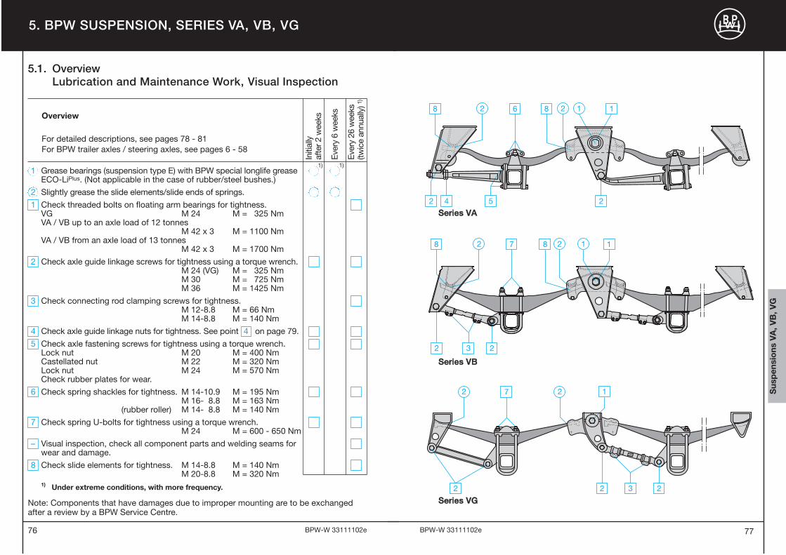
1 Grease bearings (suspension type E) with BPW special longlife greaseECO�LiPlus. (Not applicable in the case of rubber/steel bushes.)
2 Slightly grease the slide elements/slide ends of springs.
1 Check threaded bolts on floating arm bearings for tightness.VG M 24 M = 325 NmVA / VB up to an axle load of 12 tonnes
M 42 x 3 M = 1100 NmVA / VB from an axle load of 13 tonnes
M 42 x 3 M = 1700 Nm
2 Check axle guide linkage screws for tightness using a torque wrench.M 24 (VG) M = 325 NmM 30 M = 725 NmM 36 M = 1425 Nm
3 Check connecting rod clamping screws for tightness.M 12�8.8 M = 66 NmM 14�8.8 M = 140 Nm
4 Check axle guide linkage nuts for tightness. See point 4 on page 79.
5 Check axle fastening screws for tightness using a torque wrench. Lock nut M 20 M = 400 NmCastellated nut M 22 M = 320 NmLock nut M 24 M = 570 NmCheck rubber plates for wear.
6 Check spring shackles for tightness. M 14�10.9 M = 195 NmM 16� 8.8 M = 163 Nm
(rubber roller) M 14� 8.8 M = 140 Nm
7 Check spring U�bolts for tightness using a torque wrench.M 24 M = 600 � 650 Nm
– Visual inspection, check all component parts and welding seams for wear and damage.
8 Check slide elements for tightness. M 14�8.8 M = 140 NmM 20�8.8 M = 320 Nm
1) Under extreme conditions, with more frequency.
Note: Components that have damages due to improper mounting are to be exchanged after a review by a BPW Service Centre.
Overview
For detailed descriptions, see pages 78 � 81For BPW trailer axles / steering axles, see pages 6 � 58
Initi
ally
afte
r 2 w
eeks
Ever
y 6
wee
ks
Ever
y 26
wee
ks
(twic
e an
nual
ly) 1
)
8 7 8 1
232
2 2 1
8 6 8 1
5 242
2 2 1
7 1
2 3 22
2 2
SSeerriieess VVAA
SSeerriieess VVBB
SSeerriieess VVGG
1) 1)
Sus
pen
sio
ns V
A, V
B, V
G
5.1. OverviewLubrication and Maintenance Work, Visual Inspection

1 EEqquuaalliizzeerr aarrmm bbeeaarriinnggss– twice annually –
Check nuts on the equalizer arm bearingsfor tightness. The serviceable life of therubber/steel bush bearings is dependenton the tightness of the inner steel bush.Tightening torques:VG M 24 M = 325 NmVA/VB up to an axle load of 12 tonnes
M 42 x 3 M = 1100 NmVA/VB from an axle load of 13 tonnes
M 42 x 3 M = 1700 Nm
2 AAxxllee gguuiiddee lliinnkkaaggeess– twice annually, initially after 2 weeks –Check lock nuts of the axle guide link�ages/connecting rods for tightness using atorque wrench. Tightening torques: VG M 24 M= 325 NmVA/VB M 30 M = 725 NmVA/VB M 36 M = 1425 Nm
3 CCoonnnneeccttiinngg rrooddss– twice annually –Check connecting rod clamping screws fortightness. Tightening torques:
M 12�8.8 M = 66 NmM 14�8.8 M = 140 Nm
4 AAxxllee gguuiiddee lliinnkkaaggeess ((VVAA))– twice annually, initially after 2 weeks –In the case of horizontal play in the axle guidelinkages: loosen rear nut locking plate or locknut. Tighten rear nut (M 42 x 2, M 55 x 1.5,M 70 x 1.5) to tightening torque M = 100 Nmand lock. In the case of double nuts:Tighten first nut to 100 Nm, tighten secondnut to 1000 Nm, firmly locking both nutstogether using two spanners. (The frontdouble nuts (hex. nut M 36 x 2) remainlocked at 1000 Nm or locked by means ofa lock plate.)
79
1 EEqquuaalliizzeerr aarrmm bbeeaarriinnggss with bronze bushes (series VA-E, VB-E)– initially after 2 weeks then every 6 weeks –– under extreme conditions, lubricate with
more frequency –
Lift trailer to take pressure off equalizer arm bearings.Grease bronze bush bearing via the grease nipple in the heads of the threaded bolts with BPW special longlife grease ECO�LiPlus until fresh grease emerges.(Not applicable to rubber/steel bushes.)
�
2 SSlliiddee eelleemmeennttss– initially after 2 weeks then every 6 weeks –– under extreme conditions, lubricate with
more frequency –
In the case of VB suspensions with anti�vibration leaf underneath the parabolicsprings, grease the lower slide elementsvia the grease nipples.
78
5. BPW SUSPENSION, SERIES VA, VB, VG
BPW�W 33111102e BPW�W 33111102e
Sus
pen
sio
ns V
A, V
B, V
G
5.3. Maintenance Work and Visual Inspection5.2. Lubrication

8 SSlliiddee eelleemmeennttss– twice annually –Check slide elements and lateral wearplates in the shackle and equalizer arm for wear and the fastening screws fortightness. Tightening torques:M 14�8.8 M = 140 NmM 20�8.8 M = 320 NmIf necessary, check rubber rollers underthe spring ends for wear.
81
5 AAxxllee ffaasstteenniinnggss ((VVAA))– initially after 2 weeks then twice annually –Check axle fastening screws for tightnessusing a torque wrench. Tighten the 4 nutscrosswise, in the case of castle nutssecure again by means of a cotter pin. Tightening torques:Lock nut M 20 M = 400 NmCastle nut M 20 M = 320 NmLock nut M 24 M = 570 NmCheck rubber plate between axle shaftand guide linkage for wear. If the rubberplate has visibly worked its way outdownwards or upwards, replace the plate.
6 SSpprriinngg sshhaacckkllee ((VVAA))– initially after 2 weeks then twice annually –Check fastening screws of the springshackle for tightness. Tightening torques:a M 14�10.9 M = 195 Nma M 16�8.8 M = 163 Nmb M 14�8.8 M = 140 Nm
(rubber roller)c Check rubber rollers for wear and
required pretensioning of at least 1 mm.
7 SSpprriinngg UU--bboollttss– initially after 2 weeks then twice annually –Check spring U�bolts for tightness. Ifnecessary loosen lock nuts, tighten nutsalternately to the prescribed torque, and a bit at a time, then re�lock.Tightening torques:
M 24 M = 600 � 650 Nm
80 BPW�W 33111102e BPW�W 33111102e
Sus
pen
sio
ns V
A, V
B, V
G
5.3. Maintenance Work and Visual Inspection
5. BPW SUSPENSION, SERIES VA, VB, VG
– VViissuuaall iinnssppeeccttiioonn– twice annually –
Check all component parts and weldingseams for wear and damage. In order to check the bearing on theequalizer and axle guide linkage, movethe vehicle back and forth slightly with thebrake applied; or move the bearing pointswith the aid of a lever. No play should bepresent in the bearing when doing so.

8382
6. BPW SUSPENSIONS, SERIES W, BW, GW
BPW�W 33111102e BPW�W 33111102e
1 Grease axle support bearing series W, BW using BPW special longlifegrease ECO�LiPlus.
2 Grease spring tension casing series W using BPW special longlife grease ECO�LiPlus.
– Visual inspection, check all component parts and welding seams for wear and damage.
1 Check spring U�bolt of support axle for tightness.M 30 x 2�8.8 M = 980 NmM 36�8.8 M = 1555 Nm
2 Check fastening screws on the bearing covers for tightness.M 20�8.8 M = 320 NmM 24�8.8 M = 570 Nm
3 Check spring U�bolts on the spring tension casings for tightness.M 20�8.8 M = 320 NmM 20�10.9 M = 450 NmM 24�8.8 M = 570 NmM 24�10.9 M = 700 Nm
1) Under extreme conditions, with more frequency.
Note: Components that have damages due to improper mounting are to be exchanged after a review by a BPW Service Centre.
Overview
For detailed description, see pages 84 � 85BPW trailer axles / steering axles, see pages 6 � 58
Initi
ally
af
ter 2
wee
ks
Ever
y 6
wee
ks
Ever
y 26
wee
ks
(twic
e an
nual
ly) 1
)
1) 1)
SSeerriieess WW
SSeerriieess BBWW // GGWW
Sus
pen
sio
ns W
, BW
, GW
6.1. OverviewLubrication and Maintenance Work, Visual Inspection

– VViissuuaall iinnssppeeccttiioonn– twice annually –
Check all components and welding seamsfor wear and damage.
1 SSpprriinngg UU--bboollttss oonn tthhee ttrruunnnniioonn aaxxllee– twice annually, initially after 2 weeks –
Check spring U�bolts for tightness. If necessary loosen lock nuts, tighten nuts alternately to the prescribed torque, a bit at a time, then relock.Tightening torques:
M 30 x 2�8.8 M = 980 NmM 36�8.8 M = 1555 Nm
2 FFaasstteenniinngg ssccrreewwss oonn tthhee ccoovveerr ppllaatteess– twice annually –
Check the fastening screws on the coverplates of the support axle for tightness.Tightening torques:
M 20�8.8 M = 320 NmM 24�8.8 M = 570 Nm
3 SSpprriinngg UU--bboollttss oonn tthhee sspprriinngg tteennssiioonn ccaassiinnggss– twice annually –
Check spring U�bolts on the spring tension casings for tightness.If necessary loosen lock nuts, tighten nuts alternately to the prescribed torque, a bit at a time, then relock.Tightening torques:
M 20�8.8 M = 320 NmM 20�10.9 M = 450 NmM 24�8.8 M = 570 NmM 24�10.9 M = 700 Nm
85
1 SSuuppppoorrtt aaxxllee (series W, BW)– initially after 2 weeks then every 6 weeks –– under extreme conditions, lubricate with
more frequency –
Lift trailer to take pressure off the bearings. Grease lubrication nipple front and rear on the bearing brackets of the supportaxle using BPW special longlife greaseECO�LiPlus until fresh grease emerges (notapplicable to axle assembly series GW = rubber bush).
2 SSpprriinngg tteennssiioonn ccaassiinngg (series W)– initially after 2 weeks then every 6 weeks –
Grease lubrication nipples on the springtension casing using BPW special longlifegrease ECO�LiPlus.
84
6. BPW SUSPENSIONS, SERIES W, BW, GW
BPW�W 33111102e BPW�W 33111102e
Series W
Series BW
Series W Sus
pen
sio
ns W
, BW
, GW
6.3. Maintenance Work and Visual Inspection6.2. Lubrication

87BPW�W 33111102e86
Notice
BPW�W 33111102e

BPW Bergische Achsen Kommanditgesellschaft, P.O. Box 12 80, D-51656 Wiehl, Phone +49 22 62 78-0, [email protected], www.bpw.de
BP
W-W
33
11
11
02
e