“bpc960 v0” bliss powercom genset controller kirloskar ... · bpc960v0 user manual bpc960v0...
TRANSCRIPT
BPC960V0 User Manual
BPC960V0 Customer User Manual.doc Page 1 of 20 10/08/2011
“BPC960 V0” Bliss Powercom
Genset Controller
Kirloskar Electric Co. Ltd
User Manual
This document applies to Product 9001-0049
Build Version 3600-0129
Firmware Version 5000-xxxx
www.BPC.gen.nz
The information contained in this document is copyright, and
shall not be reproduced without the written authority of BPC
©2008
BPC960V0 User Manual
BPC960V0 Customer User Manual.doc Page 2 of 20 10/08/2011
BPC960V0
Manual Genset Controller 1. Introduction
The BPC960V0 is an integrated Engine and AC controller for gensets.
The unit incorporates both manual and auto start initiated start and stop sequencing, monitors engine and alternator operating parameters and provides both engine and alternator protection, in a single integrated package.
The genset operating parameters are shown by scrolling screens on a backlit 128 x 64 dot Graphics LCD. Alarms and warning are also shown on the LCD and supplemented by an alarm LED and Hooter output.
The unit provides comprehensive monitoring of the engine and generator operating parameters and provides automatic shutdown of the genset in the event of damaging conditions. In addition to the usual engine safety protections the unit monitors coolant level, fuel level, canopy temperature and generator loading to provide even more comprehensive protection.
The unit incorporates a Stop Alarm Log (10 events) to give the field service engineer the operational alarm history for easier diagnostics.
In the factory environment, the unit is configured by cloning through a PC system. Field specific parameters can be adjusted by using the front panel buttons and an inbuilt menu system.
2. Benefits
• Reduces system cost:
• Integrates engine gauges and AC metering into one unit.
• Minimises control panel wiring offering reduced material and labour costs.
• Reduces warranty costs by providing comprehensive engine and generator protection and a maintenance due timer.
• Flexible, the unit can be customised by PC cloning with application codes for individual genset
model characteristics and fitments.
BPC960V0 User Manual
BPC960V0 Customer User Manual.doc Page 3 of 20 10/08/2011
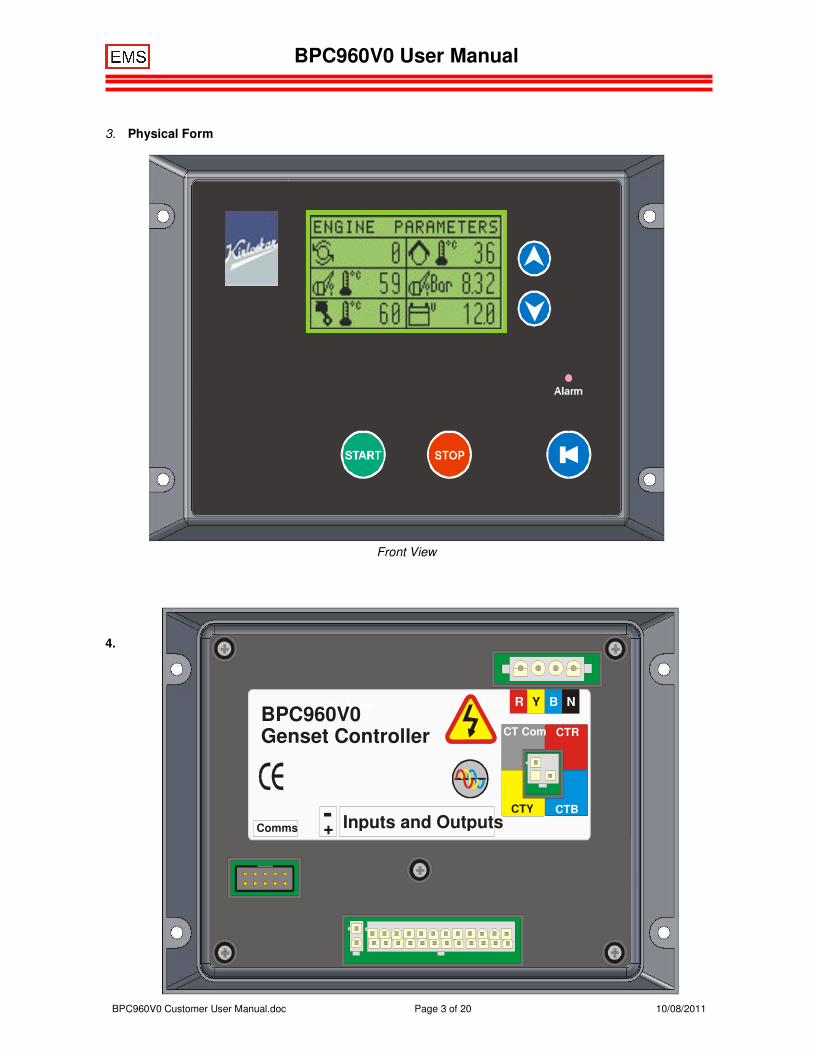
3. Physical Form
Front View
Rear View
4.
BPC960V0
Genset Controller
Inputs and Outputs+ -
Comms
R Y B N
CT Com CTR
CTY CTB
BPC960V0 User Manual
BPC960V0 Customer User Manual.doc Page 4 of 20 10/08/2011
Functions
1. Operation
Front Layout
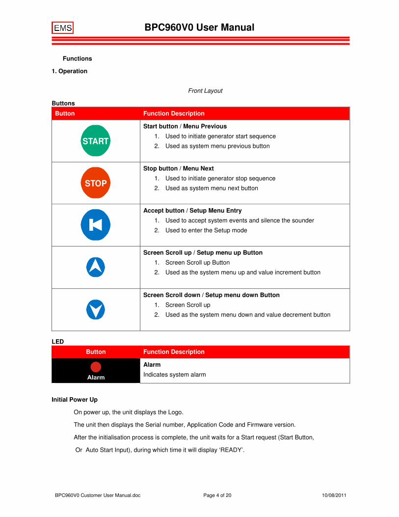
Buttons
Button Function Description
START
Start button / Menu Previous
1. Used to initiate generator start sequence
2. Used as system menu previous button
STOP
Stop button / Menu Next
1. Used to initiate generator stop sequence
2. Used as system menu next button
Accept button / Setup Menu Entry
1. Used to accept system events and silence the sounder
2. Used to enter the Setup mode
Screen Scroll up / Setup menu up Button
1. Screen Scroll up Button
2. Used as the system menu up and value increment button
Screen Scroll down / Setup menu down Button
1. Screen Scroll up
2. Used as the system menu down and value decrement button
LED
Button Function Description
Alarm
Indicates system alarm
Initial Power Up
On power up, the unit displays the Logo.
The unit then displays the Serial number, Application Code and Firmware version.
After the initialisation process is complete, the unit waits for a Start request (Start Button,
Or Auto Start Input), during which time it will display ‘READY’.
BPC960V0 User Manual
BPC960V0 Customer User Manual.doc Page 5 of 20 10/08/2011
Ready
When the unit is in READY all measuring systBPC and display systBPC are turned on. The unit remains on for 1 minute and if the genset is not started in that time the unit goes into sleep mode to conserve battery power. In this mode the unit wakes periodically to check for any unusual conditions and if it finds none it goes back to sleep, otherwise it alarms accordingly. Where ‘awake’ mode has been selected the system parameters are continuously scrolled.
Any activity on the buttons immediately wakes the unit and the appropriate action is taken.
Pressing the STOP button while the unit is asleep immediately wakes the unit and scrolls all engine and generator parameter screens. This allows reading of battery voltage, fuel level, run hours KWH etc.
Manual Operation
To start the genset
When the display is showing READY, press the start START
button momentarily to start the genset. The READY state implies the engine and generator parameters are as expected for a stationary genset. If the conditions are not as expected, an appropriate warning or alarm is displayed on the LCD. The warning or alarm condition must be cleared before the genset can be started.
The unit will perform the starting sequence as follows:
• FUEL-ON.
o If ETR (Energise To Run) fuel control is configured, the unit will control the fuel output and display FUEL ON and the proceeds to the CRANK state.
o For ETS (Energise To Stop) the sequence does not activate the output but proceeds after a short delay to the CRANK state.
•
• CRANK.
o The crank output is activated and the display shows ‘Cranking’ with a count down time.
o The crank output is deactivated when the unit has detected a speed signal above the crank disconnect speed specified in the settings, or has detected oil pressure above the minimum oil pressure specified in the settings or Excitation is present
o If the genset does not start, the LCD will show ‘Stopping’, control the Fuel and Crank outputs accordingly, and return to READY. No retries are done.
o If the unit looses power due to battery voltage drop during cranking, and the engine fires, then on regaining adequate battery voltage, the unit will continue to allow the engine to run. This typically ONLY happens with ETS fuel systBPC.
• RUN UP.
o When the engine starts, the display shows ‘Run Up’ with a count down in seconds. This allows the engine measurement system to stabilise. Over speed and loss of speed signal are the only parameters checked during Run Up.
• WARM UP
o Allows the engine to stabilise at full speed before going on load. Oil pressure and Over-speed are monitored. The display shows ‘Warm Up’ with a countdown time.
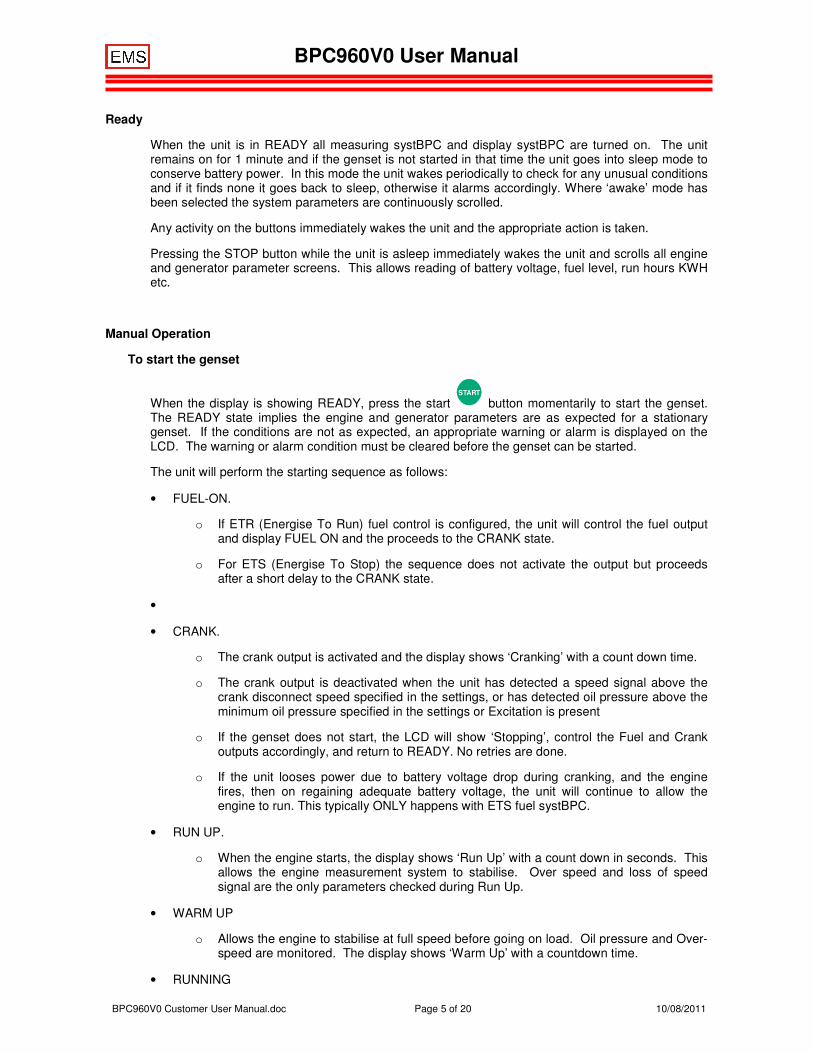
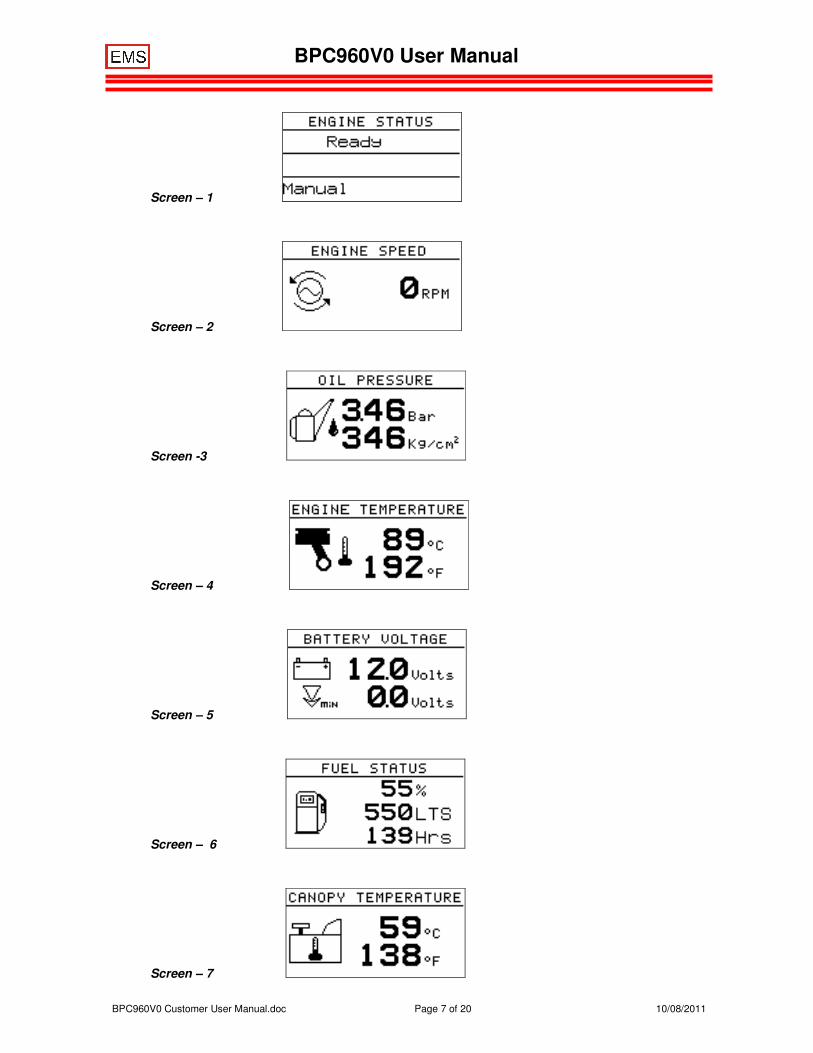
• RUNNING
BPC960V0 User Manual
BPC960V0 Customer User Manual.doc Page 6 of 20 10/08/2011
o The display shows ‘Running’. Operating parameters are scrolled onto the display.
To stop the genset
Push the STOP
button briefly.
The unit will perform a stopping sequence as follows:
• STOPPING
o The display will show ‘Stopping’ with a countdown time.
o If ETR fuel control has been selected the Fuel output will be de-energised.
o If ETS fuel control has been selected then the Fuel output will be energised for the Max Fuel Time or until the engine stops. The stopping process will retry if the engine fails to stop the first time. During the ‘ETS Rest period’ the Fuel output is deactivated.
o The fuel output is controlled until the engine stops rotating and oil pressure decays. If the Oil Pressure has not decayed by the end of the ‘Max Fuel Time’, the fuel output is deactivated and the controller waits until the oil pressure has decayed, or for the remainder of the ‘Stop Time’. The speed must remain at zero and the oil pressure must be below the alarm set point for the ‘Stop Rest Time’ before the engine is considered stopped.
o If the genset does not stop then the alarm output is activated and ‘STOP FAIL’ is displayed on the LCD.
• READY
o The engine has stopped and is ready to start again as required.
3. Display Operation
When the genset is running
When the genset is starting and stopping, the display shows the state of the sequence together with the time remaining before the next state will commence.
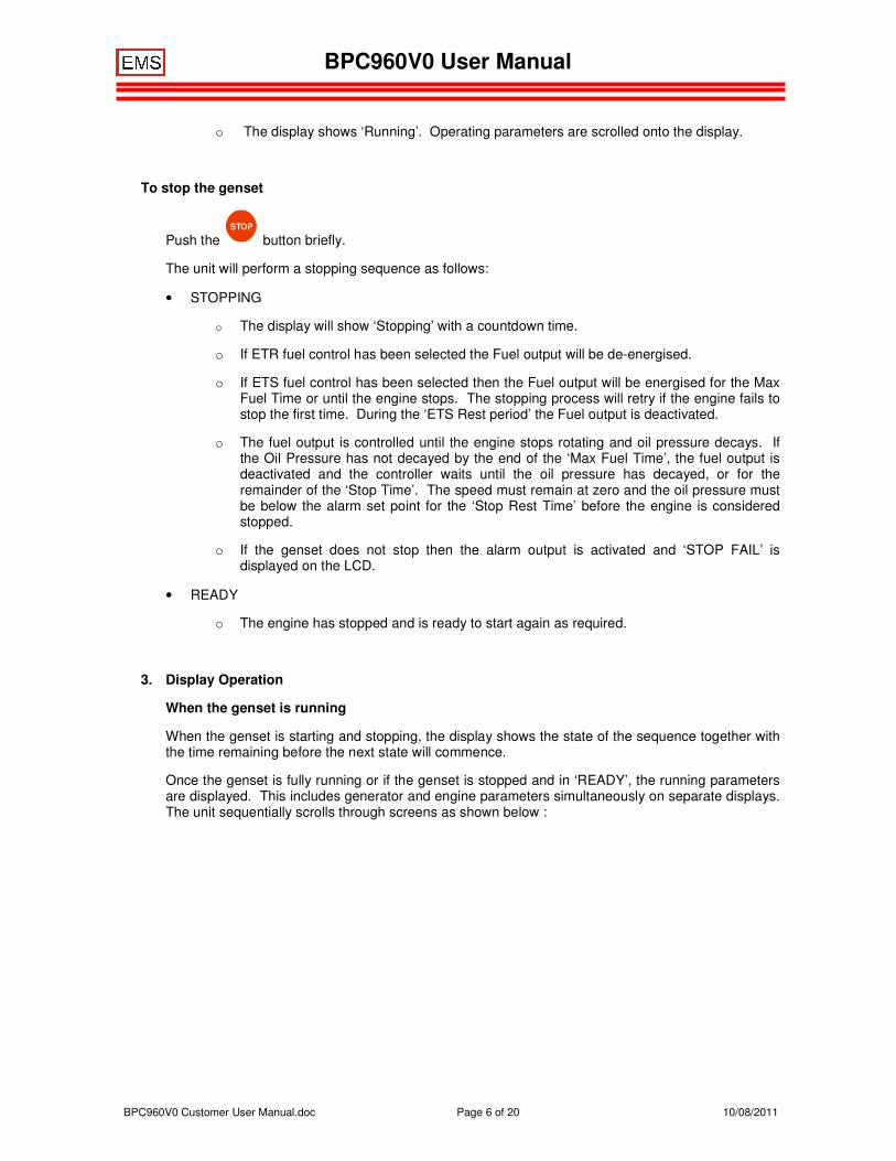
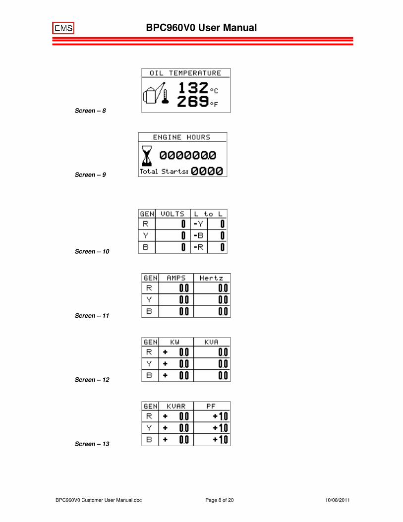
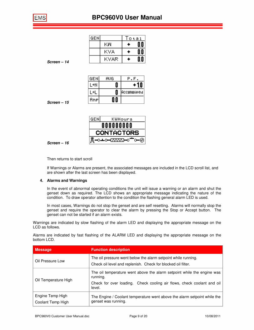
Once the genset is fully running or if the genset is stopped and in ‘READY’, the running parameters are displayed. This includes generator and engine parameters simultaneously on separate displays. The unit sequentially scrolls through screens as shown below :
BPC960V0 User Manual
BPC960V0 Customer User Manual.doc Page 7 of 20 10/08/2011
Screen – 1
Screen – 2
Screen -3
Screen – 4
Screen – 5
Screen – 6
Screen – 7
BPC960V0 User Manual
BPC960V0 Customer User Manual.doc Page 8 of 20 10/08/2011
Screen – 8
Screen – 9
Screen – 10
Screen – 11
Screen – 12
Screen – 13
BPC960V0 User Manual
BPC960V0 Customer User Manual.doc Page 9 of 20 10/08/2011
Screen – 14
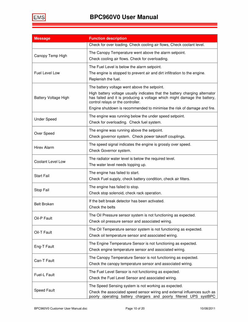
Screen – 15
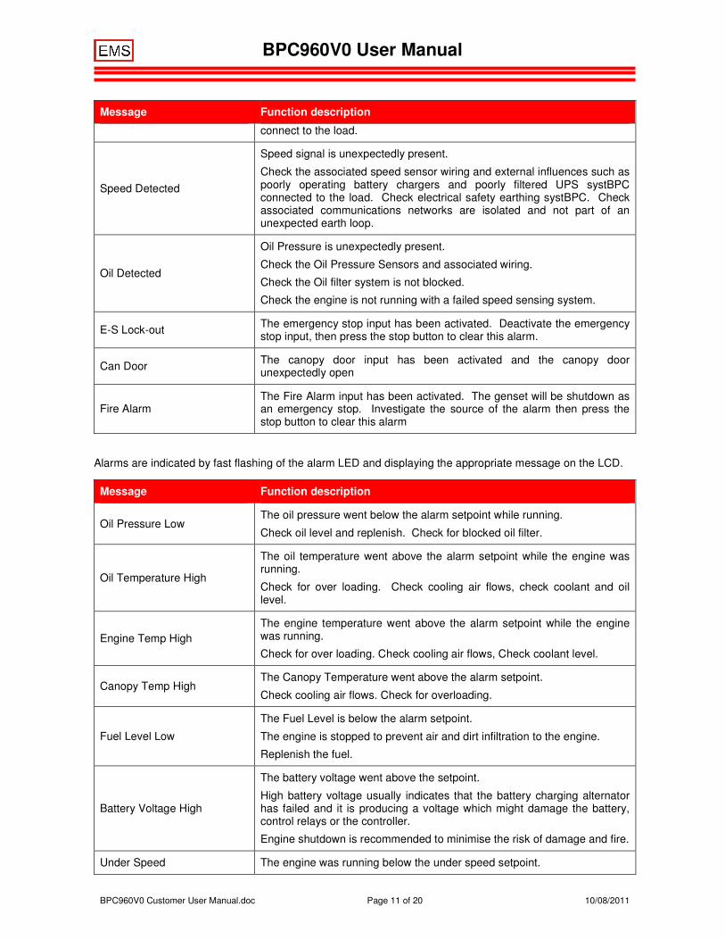
Screen – 16
Then returns to start scroll If Warnings or Alarms are present, the associated messages are included in the LCD scroll list, and are shown after the last screen has been displayed.
4. Alarms and Warnings
In the event of abnormal operating conditions the unit will issue a warning or an alarm and shut the genset down as required. The LCD shows an appropriate message indicating the nature of the condition. To draw operator attention to the condition the flashing general alarm LED is used.
In most cases, Warnings do not stop the genset and are self resetting. Alarms will normally stop the genset and require the operator to clear the alarm by pressing the Stop or Accept button. The genset can not be started if an alarm exists.
Warnings are indicated by slow flashing of the alarm LED and displaying the appropriate message on the LCD as follows.
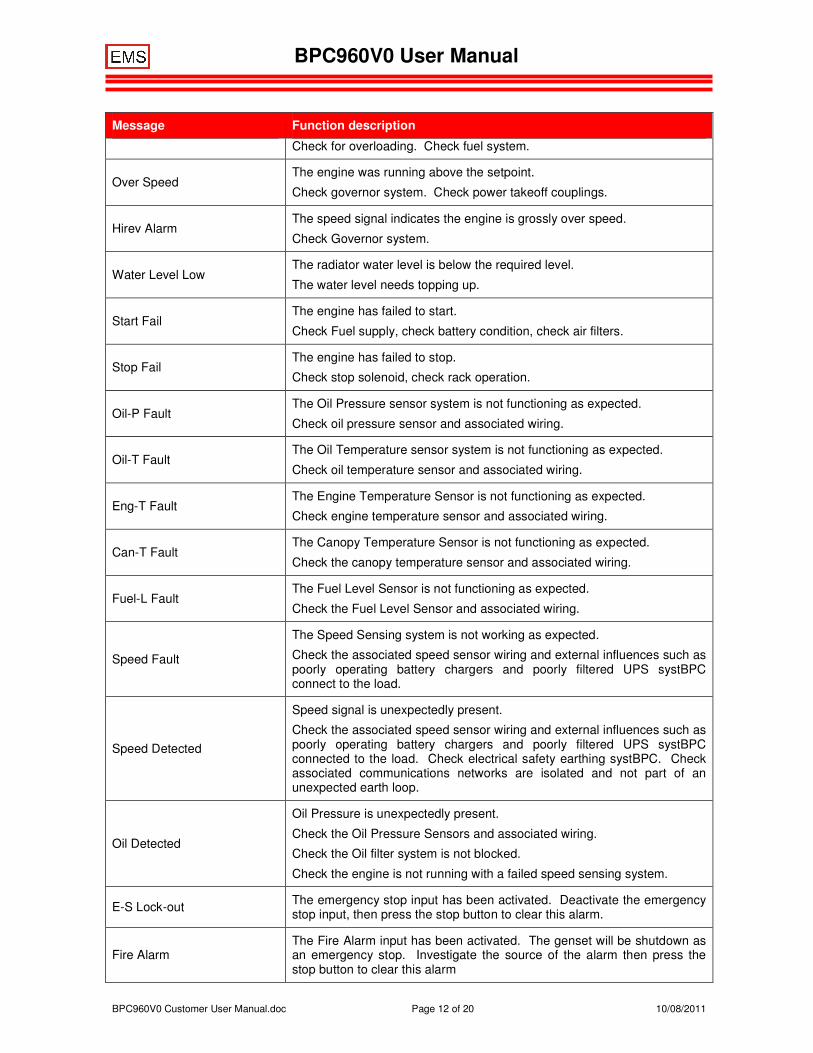
Alarms are indicated by fast flashing of the ALARM LED and displaying the appropriate message on the bottom LCD.
Message Function description
Oil Pressure Low The oil pressure went below the alarm setpoint while running.
Check oil level and replenish. Check for blocked oil filter.
Oil Temperature High
The oil temperature went above the alarm setpoint while the engine was running.
Check for over loading. Check cooling air flows, check coolant and oil level.
Engine Temp High
Coolant Temp High The Engine / Coolant temperature went above the alarm setpoint while the genset was running.
BPC960V0 User Manual
BPC960V0 Customer User Manual.doc Page 10 of 20 10/08/2011
Message Function description
Check for over loading. Check cooling air flows, Check coolant level.
Canopy Temp High The Canopy Temperature went above the alarm setpoint.
Check cooling air flows. Check for overloading.
Fuel Level Low
The Fuel Level is below the alarm setpoint.
The engine is stopped to prevent air and dirt infiltration to the engine.
Replenish the fuel.
Battery Voltage High
The battery voltage went above the setpoint.
High battery voltage usually indicates that the battery charging alternator has failed and it is producing a voltage which might damage the battery, control relays or the controller.
Engine shutdown is recommended to minimise the risk of damage and fire.
Under Speed The engine was running below the under speed setpoint.
Check for overloading. Check fuel system.
Over Speed The engine was running above the setpoint.
Check governor system. Check power takeoff couplings.
Hirev Alarm The speed signal indicates the engine is grossly over speed.
Check Governor system.
Coolant Level Low The radiator water level is below the required level.
The water level needs topping up.
Start Fail The engine has failed to start.
Check Fuel supply, check battery condition, check air filters.
Stop Fail The engine has failed to stop.
Check stop solenoid, check rack operation.
Belt Broken If the belt break detector has been activated.
Check the belts
Oil-P Fault The Oil Pressure sensor system is not functioning as expected.
Check oil pressure sensor and associated wiring.
Oil-T Fault The Oil Temperature sensor system is not functioning as expected.
Check oil temperature sensor and associated wiring.
Eng-T Fault The Engine Temperature Sensor is not functioning as expected.
Check engine temperature sensor and associated wiring.
Can-T Fault The Canopy Temperature Sensor is not functioning as expected.
Check the canopy temperature sensor and associated wiring.
Fuel-L Fault The Fuel Level Sensor is not functioning as expected.
Check the Fuel Level Sensor and associated wiring.
Speed Fault The Speed Sensing system is not working as expected.
Check the associated speed sensor wiring and external influences such as poorly operating battery chargers and poorly filtered UPS systBPC
BPC960V0 User Manual
BPC960V0 Customer User Manual.doc Page 11 of 20 10/08/2011
Message Function description
connect to the load.
Speed Detected
Speed signal is unexpectedly present.
Check the associated speed sensor wiring and external influences such as poorly operating battery chargers and poorly filtered UPS systBPC connected to the load. Check electrical safety earthing systBPC. Check associated communications networks are isolated and not part of an unexpected earth loop.
Oil Detected
Oil Pressure is unexpectedly present.
Check the Oil Pressure Sensors and associated wiring.
Check the Oil filter system is not blocked.
Check the engine is not running with a failed speed sensing system.
E-S Lock-out The emergency stop input has been activated. Deactivate the emergency stop input, then press the stop button to clear this alarm.
Can Door The canopy door input has been activated and the canopy door unexpectedly open
Fire Alarm The Fire Alarm input has been activated. The genset will be shutdown as an emergency stop. Investigate the source of the alarm then press the stop button to clear this alarm
Alarms are indicated by fast flashing of the alarm LED and displaying the appropriate message on the LCD.
Message Function description
Oil Pressure Low The oil pressure went below the alarm setpoint while running.
Check oil level and replenish. Check for blocked oil filter.
Oil Temperature High
The oil temperature went above the alarm setpoint while the engine was running.
Check for over loading. Check cooling air flows, check coolant and oil level.
Engine Temp High The engine temperature went above the alarm setpoint while the engine was running.
Check for over loading. Check cooling air flows, Check coolant level.
Canopy Temp High The Canopy Temperature went above the alarm setpoint.
Check cooling air flows. Check for overloading.
Fuel Level Low
The Fuel Level is below the alarm setpoint.
The engine is stopped to prevent air and dirt infiltration to the engine.
Replenish the fuel.
Battery Voltage High
The battery voltage went above the setpoint.
High battery voltage usually indicates that the battery charging alternator has failed and it is producing a voltage which might damage the battery, control relays or the controller.
Engine shutdown is recommended to minimise the risk of damage and fire.
Under Speed The engine was running below the under speed setpoint.
BPC960V0 User Manual
BPC960V0 Customer User Manual.doc Page 12 of 20 10/08/2011
Message Function description
Check for overloading. Check fuel system.
Over Speed The engine was running above the setpoint.
Check governor system. Check power takeoff couplings.
Hirev Alarm The speed signal indicates the engine is grossly over speed.
Check Governor system.
Water Level Low The radiator water level is below the required level.
The water level needs topping up.
Start Fail The engine has failed to start.
Check Fuel supply, check battery condition, check air filters.
Stop Fail The engine has failed to stop.
Check stop solenoid, check rack operation.
Oil-P Fault The Oil Pressure sensor system is not functioning as expected.
Check oil pressure sensor and associated wiring.
Oil-T Fault The Oil Temperature sensor system is not functioning as expected.
Check oil temperature sensor and associated wiring.
Eng-T Fault The Engine Temperature Sensor is not functioning as expected.
Check engine temperature sensor and associated wiring.
Can-T Fault The Canopy Temperature Sensor is not functioning as expected.
Check the canopy temperature sensor and associated wiring.
Fuel-L Fault The Fuel Level Sensor is not functioning as expected.
Check the Fuel Level Sensor and associated wiring.
Speed Fault
The Speed Sensing system is not working as expected.
Check the associated speed sensor wiring and external influences such as poorly operating battery chargers and poorly filtered UPS systBPC connect to the load.
Speed Detected
Speed signal is unexpectedly present.
Check the associated speed sensor wiring and external influences such as poorly operating battery chargers and poorly filtered UPS systBPC connected to the load. Check electrical safety earthing systBPC. Check associated communications networks are isolated and not part of an unexpected earth loop.
Oil Detected
Oil Pressure is unexpectedly present.
Check the Oil Pressure Sensors and associated wiring.
Check the Oil filter system is not blocked.
Check the engine is not running with a failed speed sensing system.
E-S Lock-out The emergency stop input has been activated. Deactivate the emergency stop input, then press the stop button to clear this alarm.
Fire Alarm The Fire Alarm input has been activated. The genset will be shutdown as an emergency stop. Investigate the source of the alarm then press the stop button to clear this alarm
BPC960V0 User Manual
BPC960V0 Customer User Manual.doc Page 13 of 20 10/08/2011
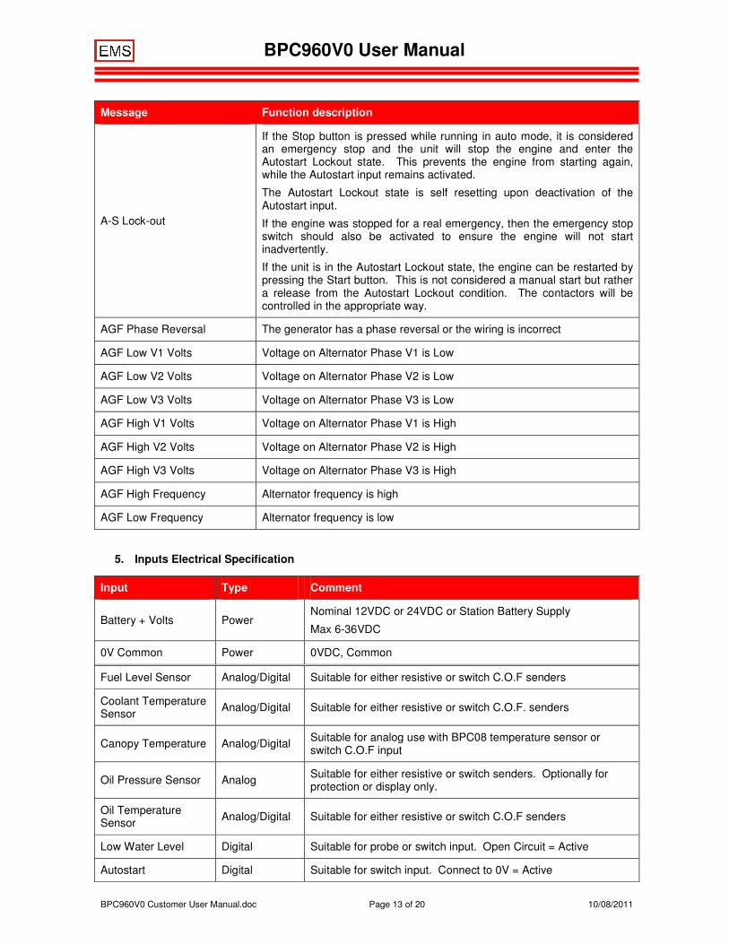
Message Function description
A-S Lock-out
If the Stop button is pressed while running in auto mode, it is considered an emergency stop and the unit will stop the engine and enter the Autostart Lockout state. This prevents the engine from starting again, while the Autostart input remains activated.
The Autostart Lockout state is self resetting upon deactivation of the Autostart input.
If the engine was stopped for a real emergency, then the emergency stop switch should also be activated to ensure the engine will not start inadvertently.
If the unit is in the Autostart Lockout state, the engine can be restarted by pressing the Start button. This is not considered a manual start but rather a release from the Autostart Lockout condition. The contactors will be controlled in the appropriate way.
AGF Phase Reversal The generator has a phase reversal or the wiring is incorrect
AGF Low V1 Volts Voltage on Alternator Phase V1 is Low
AGF Low V2 Volts Voltage on Alternator Phase V2 is Low
AGF Low V3 Volts Voltage on Alternator Phase V3 is Low
AGF High V1 Volts Voltage on Alternator Phase V1 is High
AGF High V2 Volts Voltage on Alternator Phase V2 is High
AGF High V3 Volts Voltage on Alternator Phase V3 is High
AGF High Frequency Alternator frequency is high
AGF Low Frequency Alternator frequency is low
5. Inputs Electrical Specification
Input Type Comment
Battery + Volts Power Nominal 12VDC or 24VDC or Station Battery Supply
Max 6-36VDC
0V Common Power 0VDC, Common
Fuel Level Sensor Analog/Digital Suitable for either resistive or switch C.O.F senders
Coolant Temperature Sensor Analog/Digital Suitable for either resistive or switch C.O.F. senders
Canopy Temperature Analog/Digital Suitable for analog use with BPC08 temperature sensor or switch C.O.F input
Oil Pressure Sensor Analog Suitable for either resistive or switch senders. Optionally for protection or display only.
Oil Temperature Sensor Analog/Digital Suitable for either resistive or switch C.O.F senders
Low Water Level Digital Suitable for probe or switch input. Open Circuit = Active
Autostart Digital Suitable for switch input. Connect to 0V = Active
BPC960V0 User Manual
BPC960V0 Customer User Manual.doc Page 14 of 20 10/08/2011
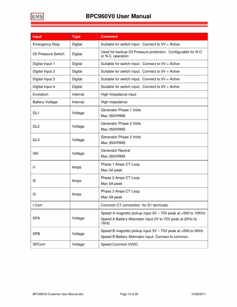
Input Type Comment
Emergency Stop Digital Suitable for switch input. Connect to 0V = Active
Oil Pressure Switch Digital Used for backup Oil Pressure protection. Configurable for N.O or N.C. operation
Digital Input 1 Digital Suitable for switch input. Connect to 0V = Active
Digital Input 2 Digital Suitable for switch input. Connect to 0V = Active
Digital Input 3 Digital Suitable for switch input. Connect to 0V = Active
Digital Input 4 Digital Suitable for switch input. Connect to 0V = Active
Excitation Internal High Impedance input
Battery Voltage Internal High Impedance
GL1 Voltage Generator Phase 1 Volts
Max 350VRMS
GL2 Voltage Generator Phase 2 Volts
Max 350VRMS
GL3 Voltage Generator Phase 3 Volts
Max 350VRMS
GN Voltage Generator Neutral
Max 350VRMS
I1 Amps Phase 1 Amps CT Loop
Max 5A peak
I2 Amps Phase 2 Amps CT Loop
Max 5A peak
I3 Amps Phase 3 Amps CT Loop
Max 5A peak
I Com Common CT connection for S1 terminals.
SPA Voltage Speed A magnetic pickup input 3V – 70V peak at >500 to 10KHz
Speed A Battery Alternator input 2V to 70V peak at 20Hz to 1KHz
SPB Voltage Speed B magnetic pickup input 3V – 70V peak at >500 to 0KHz
Speed B Battery Alternator input. Connect to common.
SPCom Voltage Speed Common 0VDC
BPC960V0 User Manual
BPC960V0 Customer User Manual.doc Page 15 of 20 10/08/2011
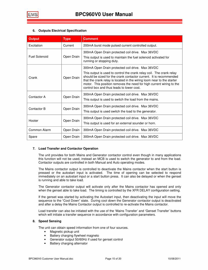
6. Outputs Electrical Specification
Output Type Comment
Excitation Current 200mA burst mode pulsed current controlled output.
Fuel Solenoid Open Drain 300mA Open Drain protected coil drive. Max 36VDC
This output is used to maintain the fuel solenoid activated for running or stopping duty.
Crank Open Drain
300mA Open Drain protected coil drive. Max 36VDC
This output is used to control the crank relay coil. The crank relay should be sized for the crank contactor current. It is recommended that the crank relay is located in the wiring loom near to the starter motor. This position removes the need for high current wiring to the control box and thus leads to lower cost.
Contactor A Open Drain 300mA Open Drain protected coil drive. Max 36VDC
This output is used to switch the load from the mains.
Contactor B Open Drain 300mA Open Drain protected coil drive. Max 36VDC
This output is used switch the load to the generator.
Hooter Open Drain 300mA Open Drain protected coil drive. Max 36VDC
This output is used for an external sounder or horn.
Common Alarm Open Drain 300mA Open Drain protected coil drive. Max 36VDC
Spare Open Drain 300mA Open Drain protected coil drive. Max 36VDC
7. Load Transfer and Contactor Operation
The unit provides for both Mains and Generator contactor control even though in many applications this function will not be used, instead an MCB is used to switch the generator to and from the load. Contactor outputs are controlled in both Manual and Auto operating modes.
The Mains contactor output is controlled to deactivate the Mains contactor when the start button is pressed or the autostart input is activated. The time of opening can be selected to respond immediately on an autostart input or a start button press. It can also be delayed or when the genset is running and able to take load.
The Generator contactor output will activate only after the Mains contactor has opened and only when the genset able to take load. The timing is controlled by the XFR DELAY configuration setting.
If the genset was started by activating the Autostart input, then deactivating the input will move the sequence to the “Cool Down” state. During cool down the Generator contactor output is deactivated and after a delay the Mains Contactor output is controlled to re-activate the Mains contactor.
Load transfer can also be initiated with the use of the ‘Mains Transfer’ and ‘Genset Transfer’ buttons which will initiate a transfer sequence in accordance with configuration parameters.
8. Speed Sensing
The unit can obtain speed information from one of four sources. • Magnetic pickup unit • Battery charging flywheel magneto • Generator output 50/60Hz if used for genset control • Battery charging alternator
BPC960V0 User Manual
BPC960V0 Customer User Manual.doc Page 16 of 20 10/08/2011
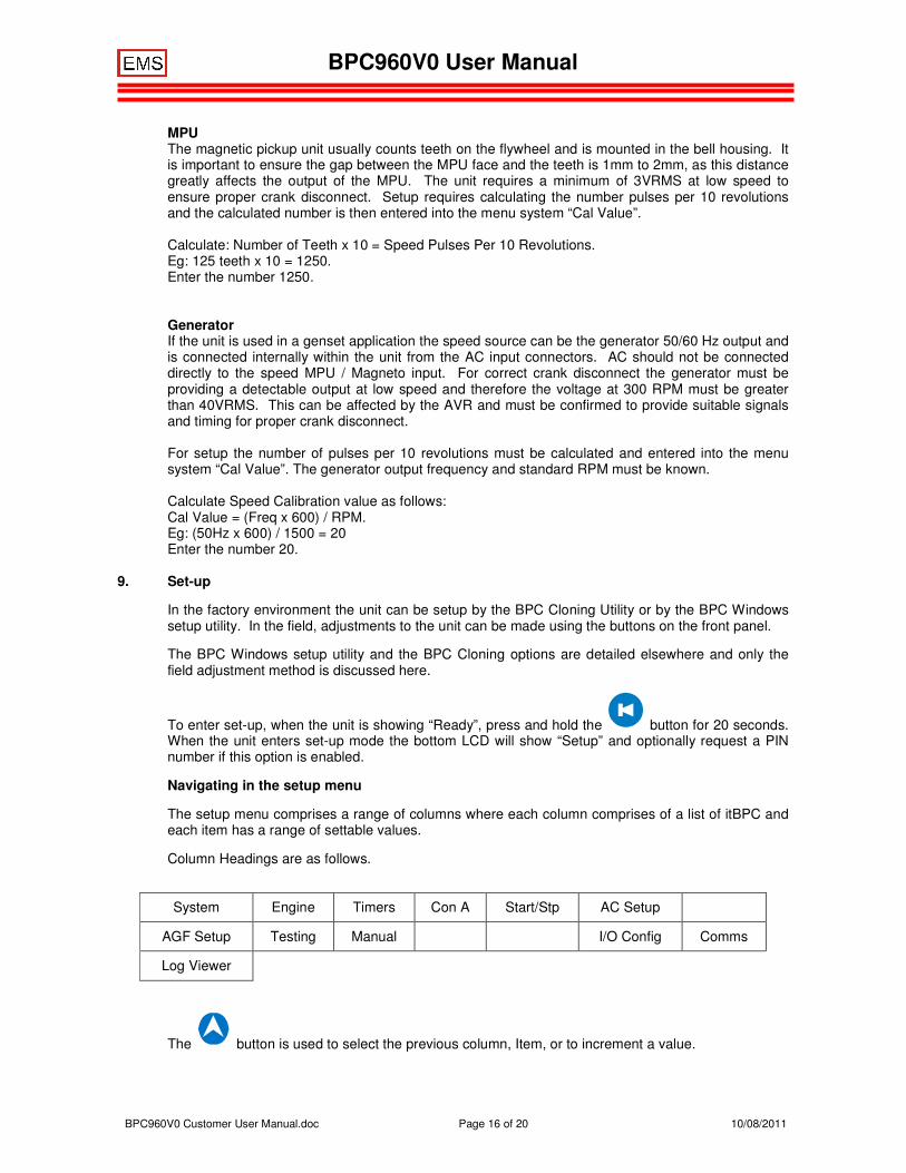
MPU The magnetic pickup unit usually counts teeth on the flywheel and is mounted in the bell housing. It is important to ensure the gap between the MPU face and the teeth is 1mm to 2mm, as this distance greatly affects the output of the MPU. The unit requires a minimum of 3VRMS at low speed to ensure proper crank disconnect. Setup requires calculating the number pulses per 10 revolutions and the calculated number is then entered into the menu system “Cal Value”. Calculate: Number of Teeth x 10 = Speed Pulses Per 10 Revolutions. Eg: 125 teeth x 10 = 1250. Enter the number 1250.
Generator If the unit is used in a genset application the speed source can be the generator 50/60 Hz output and is connected internally within the unit from the AC input connectors. AC should not be connected directly to the speed MPU / Magneto input. For correct crank disconnect the generator must be providing a detectable output at low speed and therefore the voltage at 300 RPM must be greater than 40VRMS. This can be affected by the AVR and must be confirmed to provide suitable signals and timing for proper crank disconnect. For setup the number of pulses per 10 revolutions must be calculated and entered into the menu system “Cal Value”. The generator output frequency and standard RPM must be known. Calculate Speed Calibration value as follows: Cal Value = (Freq x 600) / RPM. Eg: (50Hz x 600) / 1500 = 20 Enter the number 20.
9. Set-up
In the factory environment the unit can be setup by the BPC Cloning Utility or by the BPC Windows setup utility. In the field, adjustments to the unit can be made using the buttons on the front panel.
The BPC Windows setup utility and the BPC Cloning options are detailed elsewhere and only the field adjustment method is discussed here.
To enter set-up, when the unit is showing “Ready”, press and hold the button for 20 seconds. When the unit enters set-up mode the bottom LCD will show “Setup” and optionally request a PIN number if this option is enabled.
Navigating in the setup menu
The setup menu comprises a range of columns where each column comprises of a list of itBPC and each item has a range of settable values.
Column Headings are as follows.
The button is used to select the previous column, Item, or to increment a value.
System Engine Timers Con A Start/Stp AC Setup
AGF Setup Testing Manual I/O Config Comms
Log Viewer
BPC960V0 User Manual
BPC960V0 Customer User Manual.doc Page 17 of 20 10/08/2011
The button is used to select the next column, item, or to decrement a value.
The button changes from Column to item to value editor.
The button changes from Item to column and exit setup mode.
The button is used to accept value changes.
Setup mode automatically terminates if no button in pressed for 60 seconds, or when you press the
button with the column headers list visible.
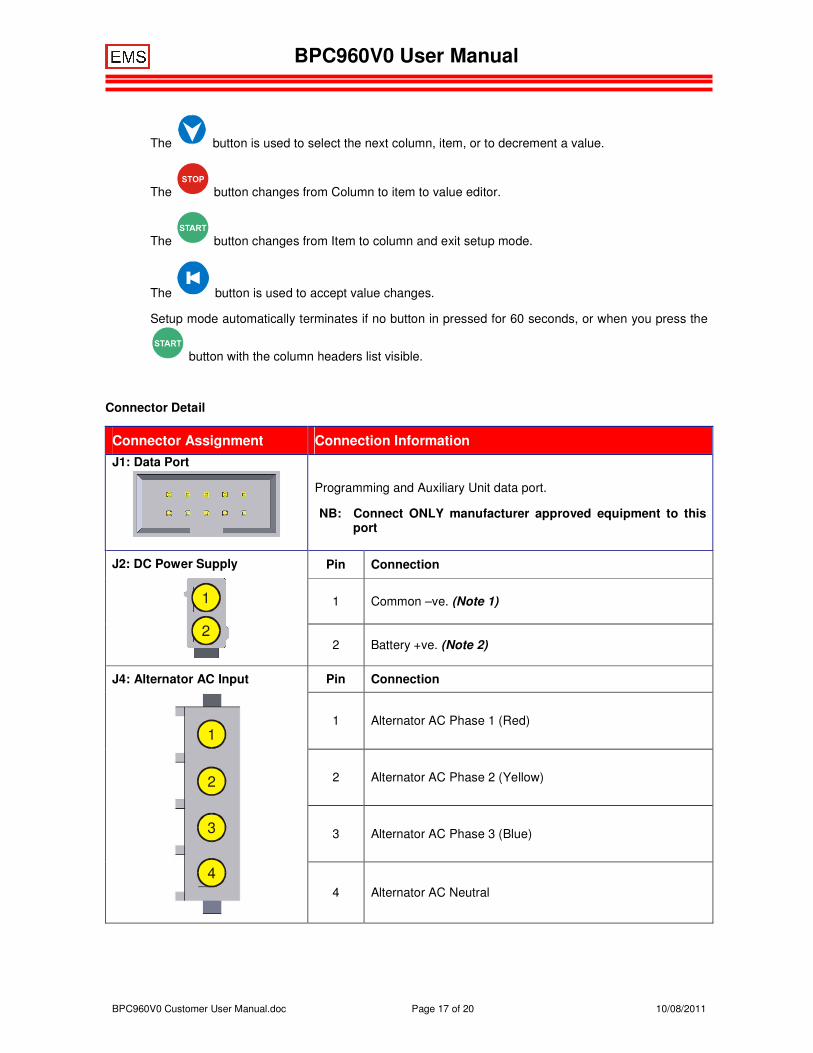
Connector Detail
Connector Assignment Connection Information J1: Data Port
Programming and Auxiliary Unit data port.
NB: Connect ONLY manufacturer approved equipment to this port
J2: DC Power Supply
1
2
Pin Connection
1 Common –ve. (Note 1)
2 Battery +ve. (Note 2)
J4: Alternator AC Input
1
2
3
4
Pin Connection
1 Alternator AC Phase 1 (Red)
2 Alternator AC Phase 2 (Yellow)
3 Alternator AC Phase 3 (Blue)
4 Alternator AC Neutral
BPC960V0 User Manual
BPC960V0 Customer User Manual.doc Page 18 of 20 10/08/2011
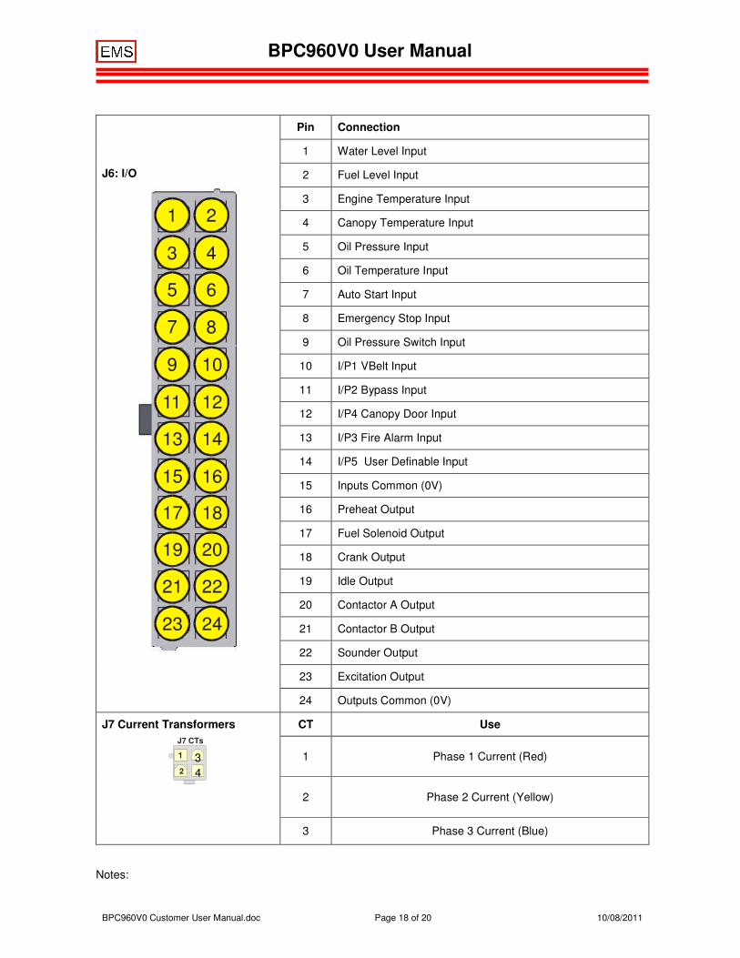
J6: I/O
1 2
3 4
5 6
7 8
9 10
11 12
13 14
15 16
17 18
19 20
21 22
23 24
Pin Connection
1 Water Level Input
2 Fuel Level Input
3 Engine Temperature Input
4 Canopy Temperature Input
5 Oil Pressure Input
6 Oil Temperature Input
7 Auto Start Input
8 Emergency Stop Input
9 Oil Pressure Switch Input
10 I/P1 VBelt Input
11 I/P2 Bypass Input
12 I/P4 Canopy Door Input
13 I/P3 Fire Alarm Input
14 I/P5 User Definable Input
15 Inputs Common (0V)
16 Preheat Output
17 Fuel Solenoid Output
18 Crank Output
19 Idle Output
20 Contactor A Output
21 Contactor B Output
22 Sounder Output
23 Excitation Output
24 Outputs Common (0V)
J7 Current Transformers
CT Use
1 Phase 1 Current (Red)
2 Phase 2 Current (Yellow)
3 Phase 3 Current (Blue)
Notes:
4 3
2 1
J7 CTs
BPC960V0 User Manual
BPC960V0 Customer User Manual.doc Page 19 of 20 10/08/2011
1. This connection must be made directly to the engine crankcase for lowest electrical noise. This connection must not have currents other than the controller currents flowing and must be used exclusively for the controller.
2. This connection must be made directly to the positive terminal of the battery for best performance. Do not make this connection to the positive terminal on the Starting Motor.
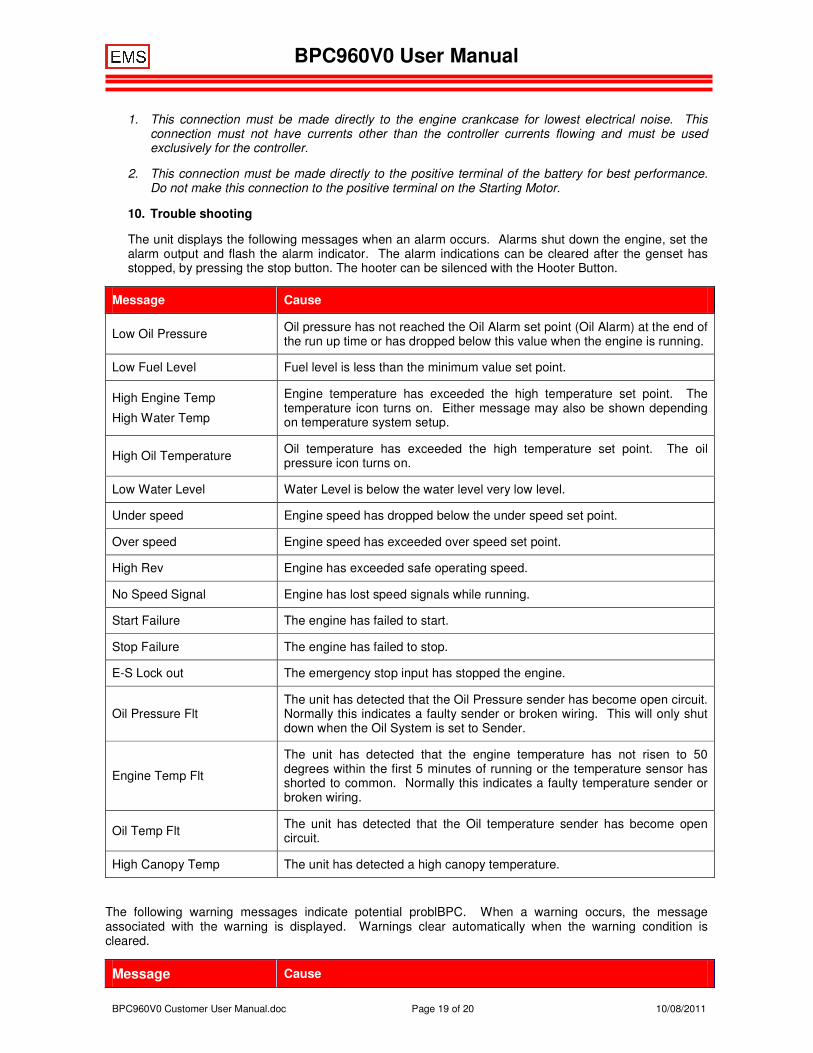
10. Trouble shooting
The unit displays the following messages when an alarm occurs. Alarms shut down the engine, set the alarm output and flash the alarm indicator. The alarm indications can be cleared after the genset has stopped, by pressing the stop button. The hooter can be silenced with the Hooter Button.
Message Cause
Low Oil Pressure Oil pressure has not reached the Oil Alarm set point (Oil Alarm) at the end of the run up time or has dropped below this value when the engine is running.
Low Fuel Level Fuel level is less than the minimum value set point.
High Engine Temp
High Water Temp
Engine temperature has exceeded the high temperature set point. The temperature icon turns on. Either message may also be shown depending on temperature system setup.
High Oil Temperature Oil temperature has exceeded the high temperature set point. The oil pressure icon turns on.
Low Water Level Water Level is below the water level very low level.
Under speed Engine speed has dropped below the under speed set point.
Over speed Engine speed has exceeded over speed set point.
High Rev Engine has exceeded safe operating speed.
No Speed Signal Engine has lost speed signals while running.
Start Failure The engine has failed to start.
Stop Failure The engine has failed to stop.
E-S Lock out The emergency stop input has stopped the engine.
Oil Pressure Flt The unit has detected that the Oil Pressure sender has become open circuit. Normally this indicates a faulty sender or broken wiring. This will only shut down when the Oil System is set to Sender.
Engine Temp Flt
The unit has detected that the engine temperature has not risen to 50 degrees within the first 5 minutes of running or the temperature sensor has shorted to common. Normally this indicates a faulty temperature sender or broken wiring.
Oil Temp Flt The unit has detected that the Oil temperature sender has become open circuit.
High Canopy Temp The unit has detected a high canopy temperature.
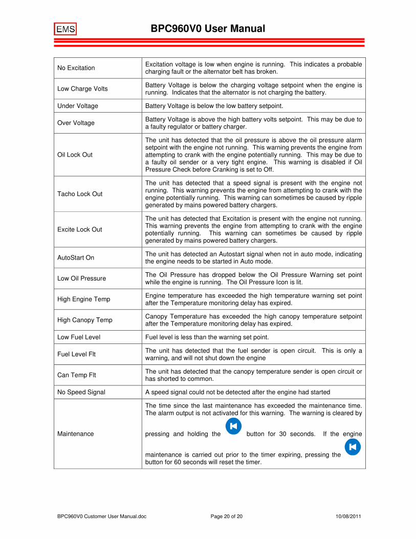
The following warning messages indicate potential problBPC. When a warning occurs, the message associated with the warning is displayed. Warnings clear automatically when the warning condition is cleared.
Message Cause
BPC960V0 User Manual
BPC960V0 Customer User Manual.doc Page 20 of 20 10/08/2011
No Excitation Excitation voltage is low when engine is running. This indicates a probable charging fault or the alternator belt has broken.
Low Charge Volts Battery Voltage is below the charging voltage setpoint when the engine is running. Indicates that the alternator is not charging the battery.
Under Voltage Battery Voltage is below the low battery setpoint.
Over Voltage Battery Voltage is above the high battery volts setpoint. This may be due to a faulty regulator or battery charger.
Oil Lock Out
The unit has detected that the oil pressure is above the oil pressure alarm setpoint with the engine not running. This warning prevents the engine from attempting to crank with the engine potentially running. This may be due to a faulty oil sender or a very tight engine. This warning is disabled if Oil Pressure Check before Cranking is set to Off.
Tacho Lock Out
The unit has detected that a speed signal is present with the engine not running. This warning prevents the engine from attempting to crank with the engine potentially running. This warning can sometimes be caused by ripple generated by mains powered battery chargers.
Excite Lock Out
The unit has detected that Excitation is present with the engine not running. This warning prevents the engine from attempting to crank with the engine potentially running. This warning can sometimes be caused by ripple generated by mains powered battery chargers.
AutoStart On The unit has detected an Autostart signal when not in auto mode, indicating the engine needs to be started in Auto mode.
Low Oil Pressure The Oil Pressure has dropped below the Oil Pressure Warning set point while the engine is running. The Oil Pressure Icon is lit.
High Engine Temp Engine temperature has exceeded the high temperature warning set point after the Temperature monitoring delay has expired.
High Canopy Temp Canopy Temperature has exceeded the high canopy temperature setpoint after the Temperature monitoring delay has expired.
Low Fuel Level Fuel level is less than the warning set point.
Fuel Level Flt The unit has detected that the fuel sender is open circuit. This is only a warning, and will not shut down the engine
Can Temp Flt The unit has detected that the canopy temperature sender is open circuit or has shorted to common.
No Speed Signal A speed signal could not be detected after the engine had started
Maintenance
The time since the last maintenance has exceeded the maintenance time. The alarm output is not activated for this warning. The warning is cleared by
pressing and holding the button for 30 seconds. If the engine
maintenance is carried out prior to the timer expiring, pressing the button for 60 seconds will reset the timer.