border crossing · pdf fileg valley crossing pipeline, llc docket no. cp17-19-000 border...
TRANSCRIPT
Valley Crossing Pipeline, LLC Docket No. CP17-19-000
Border Crossing Project
Environmental Assessment
Washington DC, 20426
Fe
dera
l Ene
rgy
Reg
ulat
ory
Comm
issi
on
Office of Energy Projects
June 2017

FEDERAL ENERGY REGULATORY COMMISSION WASHINGTON, D.C. 20426
OFFICE OF ENERGY PROJECTS
In Reply Refer To: OEP/DG2E/Gas Branch 3 Valley Crossing Pipeline, LLC
Border Crossing Project Docket No. CP17-19-000
TO THE PARTY ADDRESSED: The staff of the Federal Energy Regulatory Commission (FERC or Commission)
has prepared an environmental assessment (EA) for the Border Crossing Project (Project) proposed by Valley Crossing Pipeline, LLC (Valley Crossing). Valley Crossing proposes to construct and operate an approximately 1,000-foot-long, 42-inch-diameter, natural gas transmission pipeline in the Gulf of Mexico, across the international boundary between the United States of America and the United Mexican States (Mexico). The Project would connect the non-jurisdictional Valley Crossing System with the Mexican Marina Pipeline and facilitate the delivery/export of up to 2.6 billion cubic feet per day of natural gas to Mexico.
The EA assesses the potential environmental impacts of constructing and operating the Project in accordance with the requirements of the National Environmental Policy Act (NEPA). The FERC staff concludes that approval of the Project would not constitute a major federal action significantly affecting the quality of the human environment.
The FERC staff mailed copies of the EA to federal, state, and local government
representatives and agencies; elected officials; and interested individuals and groups. In addition, the EA is available for public viewing on the FERC’s website (www.ferc.gov) using the eLibrary link. A limited number of copies of the EA are available for distribution and public inspection at:
Federal Energy Regulatory Commission Public Reference Room
888 First Street NE, Room 2A Washington, DC 20426
(202) 502-8371
- 2 -
Any person wishing to comment on the EA may do so. Your comments should focus on potential environmental impacts, reasonable alternatives, and measures to avoid or lessen impacts. The more specific your comments, the more useful they will be. To ensure that the Commission has the opportunity to consider your comments prior to making a decision, it is important that we receive your comments in Washington, DC on or before July 31, 2017.
For your convenience, there are three methods you can use to file your comments
with the Commission. In all instances, please reference the project docket number (CP17-19-000) with your submission. The Commission encourages electronic filing of comments and has expert staff available to assist you at (202) 502-8258 or [email protected].
(1) You can file your comments electronically using the eComment feature located on the Commission's website (www.ferc.gov) under the link to Documents and Filings. This is an easy method for submitting brief, text-only comments on a project;
(2) You can also file your comments electronically using the eFiling feature on the Commission's website (www.ferc.gov) under the link to Documents and Filings. With eFiling, you can provide comments in a variety of formats by attaching them as a file with your submission. New eFiling users must first create an account by clicking on “eRegister.” You must select the type of filing you are making. If you are filing a comment on a particular project, please select “Comment on a Filing”; or
(3) You can file a paper copy of your comments by mailing them to the
following address:
Kimberly D. Bose, Secretary Federal Energy Regulatory Commission 888 First Street NE, Room 1A Washington, DC 20426
Any person seeking to become a party to the proceeding must file a motion to intervene pursuant to Rule 214 of the Commission's Rules of Practice and Procedures (18 CFR 385.214).1 Only intervenors have the right to seek rehearing of the Commission's decision. The Commission grants affected landowners and others with environmental concerns intervenor status upon showing good cause by stating that they have a clear and direct interest in this proceeding that no other party can adequately
1 See the previous discussion on the methods for filing comments.

- 3 - represent. Simply filing environmental comments will not give you intervenor status, but you do not need intervenor status to have your comments considered.
Additional information about the project is available from the Commission's
Office of External Affairs, at (866) 208-FERC, or on the FERC website (www.ferc.gov) using the eLibrary link. Click on the eLibrary link, click on “General Search,” and enter the docket number excluding the last three digits in the Docket Number field (i.e., CP17-19). Be sure you have selected an appropriate date range. For assistance, please contact FERC Online Support at [email protected] or toll free at (866) 208-3676, or for TTY, contact (202) 502-8659. The eLibrary link also provides access to the texts of formal documents issued by the Commission, such as orders, notices, and rulemakings.
In addition, the Commission offers a free service called eSubscription that allows you to keep track of all formal issuances and submittals in specific dockets. This can reduce the amount of time you spend researching proceedings by automatically providing you with notification of these filings, document summaries, and direct links to the documents. Go to www.ferc.gov/docs-filing/esubscription.asp.

i
Border Crossing Project
FERC Docket No. CP17-19-000
TABLE OF CONTENTS
A. PROPOSED ACTION ........................................................................................................ 5
1.0 Introduction ....................................................................................................................... 5
2.0 Purpose and Need for the Project ...................................................................................... 5
3.0 Proposed Facilities ............................................................................................................ 6
4.0 Related and Non-jurisdictional Facilities .......................................................................... 6
5.0 Public Review and Comments .......................................................................................... 7
6.0 Land (Seafloor) Requirements .......................................................................................... 7
7.0 Construction Procedures .................................................................................................... 8
8.0 Operation and Maintenance ............................................................................................... 8
9.0 Environmental Compliance ............................................................................................... 8
10.0 Permits, Approvals, and Regulatory Consultations ........................................................... 8
B. ENVIRONMENTAL ANALYSIS ................................................................................... 11
1.0 Seafloor (Sediments) ....................................................................................................... 11
2.0 Water Resources .............................................................................................................. 12
3.0 Aquatic Wildlife and Fisheries ........................................................................................ 13
4.0 Protected Species and Habitats ........................................................................................ 13
5.0 Use of Marine Waters (Land Use) .................................................................................. 14
6.0 Cultural Resources .......................................................................................................... 15
7.0 Air Quality and Noise ...................................................................................................... 16
8.0 Reliability and Safety ...................................................................................................... 17
9.0 Cumulative Impacts ......................................................................................................... 18
10.0 Related Facilities ............................................................................................................. 21
C. ALTERNATIVES............................................................................................................. 26
D. CONCLUSIONS AND RECOMMENDATIONS ........................................................... 27
ii
LIST OF TABLES
Table 1 Permits, Approvals, and Regulatory Consultations
Table 10.1 Estimated Range of Construction Emissions
Table 10.2 Estimated Compressor Station Operational Emissions
LIST OF APPENDICES
Appendix A Turbidity Modeling
Appendix B List of Preparers

iii
TECHNICAL ACRONYMS AND ABBREVIATIONS
ACHP Advisory Council on Historic Preservation APE area of potential effect AQCR Air Quality Control Regions CAA Clean Air Act CFR Code of Federal Regulations CH4 methane CEQ Council on Environmental Quality CO carbon monoxide CO2 carbon dioxide Commission Federal Energy Regulatory Commission DOE Department of Energy DOE/FE Department of Energy – Office of Fossil Energy EA Environmental Assessment EFH Essential Fish Habitat EI environmental inspector EPA Environmental Protection Agency ESA Endangered Species Act FERC Federal Energy Regulatory Commission GHG greenhouse gas HAP hazardous air pollutant MAOP maximum allowable operating pressure MMBtu/d million British thermal units per day NO2 nitrous dioxide NOx nitrous oxide NAAQS National Ambient Air Quality Standards NEPA National Environmental Policy Act NGA Natural Gas Act NHPA National Historic Preservation Act NMFS National Marine Fisheries Service NRHP National Register of Historic Places NSPS New Source Performance Standards NOA Notice of Application NOI Notice of Intent NPDES National Pollutant Discharge Elimination System O3 ozone PCB polychlorinated bi-phenyl compounds PM2.5 particulate matter less than 2.5 microns in diameter PM10 particulate matter less than 10 microns in diameter Project Border Crossing Project PSD Prevention of Significant Deterioration RCT Railroad Commission of Texas SHPO State Historic Preservation Office SPCCP Spill Prevention, Containment, and Countermeasures Plan SO sulfur dioxide USACE United States Army Corps of Engineers USC United States Code USDOT U.S. Department of Transportation

iv
5
A. PROPOSED ACTION
1.0 Introduction
On November 21, 2016, Valley Crossing Pipeline, LLC (Valley Crossing) pursuant to Section 3 of the Natural Gas Act (NGA) filed an application with the Federal Energy Regulatory Commission (FERC or Commission) seeking authorization to site, construct, operate, and maintain certain natural gas transmission facilities for the purpose of exporting or importing natural gas between the United States and Mexico. These facilities are referred to as the Border Crossing Project (Project). Valley Crossing is also seeking the issuance of a Presidential Permit pursuant to Subpart C of Part 153 of the Commission’s regulations.
This environmental assessment (EA) describes the environment that would be affected by the Project; assesses the potential impacts on the environment that would likely result from implementation of the proposed action; assesses reasonable alternatives to the proposed action; and as necessary, includes recommendations to avoid, minimize or mitigate potential adverse impacts. We1 have prepared this EA in compliance with the requirements of the National Environmental Policy Act (NEPA) (40 Code of Federal Regulations [CFR] Parts 1500-1508), and the Commission’s implementing regulations (18 CFR, Part 380).
2.0 Purpose and Need for the Project
The Project would connect the non-jurisdictional intrastate Valley Crossing System also constructed by Valley Crossing with the Comision Federal de Electricidad’s Marina Pipeline. The purpose of the Project is to provide the border crossing facilities that would connect the two pipelines.
The FERC is the federal agency responsible for evaluating applications pursuant to section 3 of the NGA for natural gas import and export facilities, and for Presidential Permits which are necessary pursuant to Executive Order 10485 when export/import facilities are to be constructed at international borders. Under Section 3 of the NGA, the FERC considers as part of its decision to authorize natural gas facilities, all factors bearing on the public interest. Specifically, regarding whether to authorize natural gas facilities used for importation or exportation, the FERC shall authorize the proposal unless it finds that the proposed facilities will not be consistent with the public interest.
Section 3 of the NGA also requires prior approval from the Department of Energy (DOE) for the import and/or export of natural gas from or to a foreign country. Section 3(c) of the NGA, as amended by section 201 of the Energy Policy Act of 1992 (Public Law 102-148), requires that import and export of natural gas applications to the DOE - Office of Fossil Energy (DOE/FE) from and to any nation with which the United States currently has or in the future will have a Free Trade Agreement be deemed consistent with the public interest and granted without
1 “We,” “us,” and “our” refer to the environmental staff of the FERC’s Office of Energy Projects.

6
modification or delay. In its application, Valley Crossing indicates that it will acquire all necessary DOE authorizations.
3.0 Proposed Facilities
Valley Crossing proposes to construct and operate approximately 1,000 feet of 42-inch-diameter natural gas transmission pipeline across the international boundary between the United States and Mexico. The Project would be located in the Gulf of Mexico about 30 miles east of Brownsville, Texas and would be capable of delivering up to 2.6 billion cubic feet per day of natural gas. The figure below illustrates the general location of the proposed pipeline.
4.0 Related and Non-jurisdictional Facilities
We received several comments on the Valley Crossing System. As previously indicated, the Project would connect the non-jurisdictional Valley Crossing System and the Marina Pipeline. The Valley Crossing System is an intrastate pipeline (wholly located within the State of Texas) regulated by the Railroad Commission of Texas (RCT). On September 15, 2016, RCT issued Valley Crossing a permit to operate its proposed system. The Commission has no authority to approve or deny the Valley Crossing System and no ability to require the avoidance or minimization of related impacts; however, we disclose available resource impact information
7
for the Valley Crossing System in the Related Facilities section of this EA to inform decision makers, concerned citizens, and other stakeholders. The Marina Pipeline is located in Mexico and therefore, not subject to U.S. laws and regulations. The Valley Crossing System and Marina Pipeline projects are also considered in the Cumulative Impacts section of this EA.
The intrastate Valley Crossing System consists of approximately 165 miles of 48-inch- and 42-inch-diameter natural gas transmission pipeline, numerous interconnects, and associated facilities, and two compressor stations (Nueces and Brownsville Compressor Stations). The Valley Crossing System would originate in Nueces County and would traverse Kleberg, Kenedy, Willacy, and Cameron Counties before connecting to the Project.
According to Valley Crossing, the non-jurisdictional Marina Pipeline would consist of approximately 500 miles of 42-inch- and 36-inch-diameter natural gas transmission pipeline and associated facilities between its interconnection with the Project and a point near Tuxpan in the state of Veracruz.
5.0 Public Review and Comments
The Commission’s administrative record, FERC Docket No. CP17-19-000, includes Valley Crossing filings, staff issuances, public comments, and other project-related documents. These documents are accessible to the public through the Commission’s eLibrary.2
On December 2, 2016, the Commission issued a Notice of Application (NOA) in response to the filing of Valley Crossing’s application. On January 27, 2017, the Commission issued a Notice of Intent to Prepare an Environmental Assessment for the Proposed Border Crossing Project and Request for Comments on Environmental Issues (NOI). The NOI was mailed to federal, state, and local government representatives and agencies; elected officials; and other interested individuals and groups. With the issuance of the NOI, a 30-day public comment period was initiated to gather input from the public and other interested agencies about the Project. In response to the NOI, the Commission received 18 comment letters from concerned citizens pertaining to the non-jurisdictional Valley Crossing System; the need for an environmental impact statement that includes the Valley Crossing System and other jurisdictional projects; and nearby proposed liquefied natural gas export projects. Three commenters expressed concerns specific to the Project. These concerns are for water quality, methane pollution, aquatic/marine life including threatened and endangered species, pipeline integrity, climate change, and cumulative impacts. We considered these comments and as appropriate, they are addressed in our environmental analysis.
6.0 Land (Seafloor) Requirements
Valley Crossing would install the pipeline within a 50-foot-wide construction corridor, encompassing approximately 1.1 acres of seafloor. Additionally, barge anchors (and anchor cable sweeps) would impact numerous sections of seafloor, totaling approximately 100 acres. 2 The Commission’s eLibrary is accessible at www.ferc.gov. To review Project documents, select “General Search” from the eLibrary menu, enter docket number CP17-19 in the “Docket Number” field, and select an appropriate date range.
8
The pipeline would be buried with at least 3 feet of cover, to a depth of approximately 8 feet. As discussed in the Water Resources section of this EA, additional seafloor may be affected by turbidity and sedimentation.
7.0 Construction Procedures
As described by Valley Crossing, a pipe lay barge (positioned with anchors) would be used to weld the pipeline, coat the pipeline with concrete, and then place the pipeline on the seafloor. The depth to seafloor is approximately 90 feet. A bury barge (also positioned by anchors) would facilitate the placement of the pipeline under the seafloor. The pipeline would be buried using “jetting” techniques. A jetting sled uses high pressure water and air to disperse sediments, creating a trench under the pipeline. Jetting techniques would then be used to cover the pipeline. Once complete, the pipeline would be hydrostatically tested using approximately 72,000 gallons of water. This water would be sourced from available seawater or would be obtained from an onshore groundwater well. Supplements may be added and after testing, water would be discharged into the Gulf of Mexico in accordance with the National Pollutant Discharge Elimination System water discharge permit. To ensure impacts on the environment are avoided and minimized, Valley Crossing would implement measures contained in its Spill Prevention, Containment, and Countermeasures Plan (SPCCP) and Unanticipated Discovery Plan. Valley Crossing anticipates completing the Project within 30 days.
8.0 Operation and Maintenance
Valley Crossing would operate and maintain the pipeline in compliance with the requirements of the U.S. Department of Transportation’s Office of Pipeline Safety (49 CFR Part 192). Valley Crossing would periodically inspect the pipeline by running an in-line inspection tool through the pipeline.
9.0 Environmental Compliance
Valley Crossing would train all construction personnel on environmental commitments, permit/authorization conditions, and other compliance requirements. As applicable, construction managers would be provided copies of all compliance related documents. Additionally, an environmental inspector would be present and would be responsible for ensuring the Project’s compliance with all environmental permits and authorizations.
10.0 Permits, Approvals, and Regulatory Consultations
As identified in the table below, Valley Crossing would be responsible for obtaining and completing all necessary permits, approvals, and consultations prior to construction of the Project.
9
Table 1 Permits, Approvals, and Regulatory Consultations
Agency/Organization Permit/Approval or
Consultation Date Submitted Date Received
Federal Energy Regulatory Commission (FERC)
Natural Gas Act Section 3 Authorization, Presidential Permit
November 21, 2016 Pending
Department of Energy (DOE)
Blanket Authorization Anticipated first quarter 2017
Pending
U.S. Army Corps of Engineers (USACE)
Authorization under Section 404 of the Clean Water Act and Section 10 of the Rivers and Harbors Act under Nationwide Permit 12
October 21, 2016 Pending
National Marine Fisheries Service (NMFS)
Consultation under Magnuson-Stevens Fishery Conservation and Management Act for adverse effects to Essential Fish Habitat
N/A N/A
U.S. Environmental Protection Agency
National Pollutant Discharge Elimination System (NPDES)
Anticipated fourth quarter 2016
Pending
Texas Historical Commission (THC)
National Historic Preservation Act, Section 106 Compliance
Anticipated first quarter 2017
Pending
Railroad Commission of Texas (RCT)
401 Water Quality Certification
N/A RCT has previously issued a 401 water quality certification for use with USACE Nationwide Permit 12 in the State of Texas
10
Table 1 Permits, Approvals, and Regulatory Consultations
Agency/Organization Permit/Approval or
Consultation Date Submitted Date Received
Coastal Zone Management Act Consistency Determination
N/A RCT has previously issued a consistency determination for use with USACE Nationwide Permit 12 in the State of Texas
T-4 Permit Received on September 15, 2016
Texas General Land Office (TxGLO)
State Land Use Lease
Pending
11
B. ENVIRONMENTAL ANALYSIS
This analysis describes the condition of the existing natural and human environment and the potential impacts on it resulting from installation and operation of the pipeline. Based on the scope of the Project and its location in the Gulf of Mexico (approximately 30 miles east of Brownsville, Texas), we have determined that groundwater, geological resources (mineral extraction and geological hazards), wetlands, vegetation, terrestrial wildlife, and migratory birds are not present or would not be affected by the Project; therefore, these resources are not considered nor addressed further in this analysis.
This analysis generally describes, as necessary, temporary, short-term, long-term, and permanent impacts and effects. A temporary effect generally occurs during construction with the resource returning to pre-construction condition immediately after restoration or within a few months. A short-term effect could continue for up to 3 years following construction. Long-term effects would last more than 3 years, but the affected resource would eventually recover to pre-construction conditions. A permanent effect would result from an activity that modifies a resource to the extent that it would not return to pre-construction conditions. As appropriate, our analysis also addresses direct and indirect effects.
1.0 Seafloor (Sediments)
According to the Texas Coastal Sediments Geodatabase, the seafloor in the Project area is comprised primarily of sand with silt and clay components. No contaminated sediments are known in the area. Installing the pipeline would directly disturb approximately 1.1 acres of seafloor. This disturbance would result primarily from jetting which would be used, as described previously, to create the pipeline trench by pushing (displacing) sediments into piles (and back over the pipeline) and subsequently into the water column. Anchors associated with the construction barges would also disturb seafloor sediments (see additional discussion below). Displacing sediments into the water column would result in a plume(s) that would drift across a larger area. Eventually, sediments within the plume(s) would fall out and settle on adjacent seafloor (sediment deposition). In response to a request for additional environmental information regarding sediment plumes, Valley Crossing conducted a sediment transport analysis to more accurately describe the impacts of the Project. The findings of Valley Crossing’s Border Crossing Pipeline Sediment Plume Modeling report are summarized below and the report, in its entirety is available in Appendix A – Turbidity Report.
Modeling performed by Valley Crossing indicates that gulf currents would generally distribute disturbed sediments in a northeast direction. Assuming high and normal wind conditions, Valley Crossing estimates that project-related sediments could travel for 3-4 days, between 1-4 miles, and covering 655 to 1,275 acres of seafloor. Valley Crossing also estimates 12 inches of sediment deposition immediately adjacent to the Project area, covering approximately 1-5 acres of seafloor, gradually diminishing as distance from the construction work area increases, with 0.5 inch of sediment covering approximately 70-81 acres of seafloor, and 0.06 inch of sediment covering 655-1,275 acres of seafloor. Additionally, as described
12
previously, anchored barges would be used to install the pipeline. According to Valley Crossing, up to 16 anchors, spanning outwards up to 2,000 feet would be used to stabilize and maneuver the barges. Anchor drops as well as drags across the seafloor resulting from currents and tidal/wave actions would impact approximately 94.8 acres of seafloor. To minimize the impacts of anchor drops and drags, Valley Crossing contractors would maintain anchor cable tension and actively monitor anchoring activities/positions.
The jetting and anchoring activities would disturb sediments and result in the displacement of sediments into the water column. Displaced sediments would be deposited on nearby seafloor altering existing contours. Displaced sediments would also affect water quality and aquatic wildlife and fisheries. These resources are addressed later in this analysis.
Direct seafloor disturbance and indirect impacts on adjacent seafloor would be temporary, minor, and localized. Additionally, naturally occurring currents and wave action would redistribute deposited sediments. Therefore, based on the characteristics of the seafloor, the scope of the Project, and the amount of resulting deposition, we conclude that installing and operating the pipeline would not significantly affect sediments in the Project area.
2.0 Water Resources
The Gulf of Mexico is a semi-enclosed oceanic system whose characteristics are primarily defined by its general configuration, currents, and freshwater inflows. According to the Gulf of Mexico Coastal Ocean Observing System, the average water temperature in the Project area is 71 degrees Fahrenheit, salinity is 36 practical salinity units, and dissolved oxygen is 5.59 parts per million.
As described in the previous section, installing the pipeline would displace sediment into the Gulf of Mexico. The sediment plumes (displaced sediment into the water column) resulting from installation of the pipeline would vary in size depending on the installation activity. The displacement of sediments to create a trench and then bury the pipeline would result in the largest sediment plumes while anchor drags and drops would result in smaller sediment plumes. Modeling performed by Valley Crossing, indicates that sediments would generally drift in a northeast direction for up to for 3-4 days and between 1-4 miles. As the sediment plume(s) drifts away from the initial point(s) of disturbance the concentration of the plume would decrease as sediments begin falling out (deposition, see previous section).
The introduction of sediment into the water column would increase turbidity and temporarily, adversely affect water quality. Valley Crossing estimates that turbidity attributable to installation activities would range from 1.5 to 150 milligrams per liter (mg/L). Impacts on water quality would be greatest closest to the point of disturbance and would gradually decrease with distance and time as sediments are deposited on adjacent seafloor. Decreased water quality and the deposition of sediment into adjacent areas could affect aquatic fisheries and wildlife. These resources are addressed later in this analysis.
13
Based on the scope of the Project, and the expected concentrations and durations of the resulting sediments plumes as well as the distances traveled, we conclude that installing and operating the pipeline would not significantly affect water quality.
3.0 Aquatic Wildlife and Fisheries
The Project area consists of common seafloor dwelling (benthic) organisms, small aquatic organisms (microbiota), worms, mollusks, crustaceans, sea turtles, and marine birds, collectively referred to as aquatic wildlife. Aquatic wildlife would be affected by installation of the pipeline. The use of barges and the direct displacement of sediments necessary for installation of the pipeline could increase the rates of stress, injury, and mortality experienced by aquatic wildlife and would result in the temporary loss of aquatic habitat. The deposition of sediments onto adjacent seafloor resulting from sediment introduced into the water column could also increase the rates of stress, injury, and mortality experienced by aquatic wildlife. However, aquatic wildlife, due to the dynamic nature of the Gulf of Mexico (currents, wave/tidal action and existing vessel use) are acclimated to some disturbance and should only be temporarily affected by installation of the pipeline.
The Gulf of Mexico is a saltwater fishery that supports a variety of fish including several protected and managed fisheries (see Protected Species and Habitats below). The Texas Parks and Wildlife Department identifies several fish species occurring in its open waters including striped mullet (Mugil cephalus), American eel (Anguilla rostrata), red drum (Sciaenops ocellatus), black drum (Pogonias cromis), tarpon (Megalops atlanticus), greater amberjack (Seriola dumerili), Florida pompano (Trachinotus carolinus), crevalle jack (Caranx hippos), tripletail (Lobotes surinamensis), and cobia (Rachycentron canadum). The Gulf of Mexico is also home to black tip sharks (Carcharhinus limbatus), nurse sharks (Ginglymostoma cirratum), bull sharks (Carcharhinus leucas), and hammerhead sharks (Sphyrna spp.).
As described in the previous section, installing the pipeline would temporarily increase turbidity and decrease water quality. Lower water quality could result in reduced fitness; avoidance and displacement which could increase the rates of stress and injury experienced by fish; and increased predation which would result in higher rates of mortality. However, because impacts on water quality would be temporary, the resulting impacts on fish would also be temporary.
Based on the scope of the Project and the temporary impacts on aquatic wildlife and fisheries, we conclude that installing and operating the pipeline would not significantly affect these resources.
4.0 Protected Species and Habitats
According to the National Marine Fisheries Services (NMFS), the Gulf of Mexico is home to several federally-listed threatened and endangered species. The sei whale (Balaenoptera borealis), fin whale (Balaenoptera physalus), humpback whale (Megaptera novaeangliae), sperm whale (Physeter macrocephalus); lobed star coral (Orbicella annularis),
14
mountainous star coral (Orbicella faveolata), boulder star coral (Orbicella franksi), elkhorn coral (Acropora palmate), Atlantic hawksbill sea turtle (Eretmochelys imbricata), green sea turtle (Chelonia mydas), Kemp’s ridley sea turtle (Lepidochelys kempii), leatherback sea turtle (Dermochelys coriacea), and loggerhead sea turtle (Caretta caretta) are all known to occur in the Gulf of Mexico.
The whale species identified above are generally restricted to deeper offshore waters. Therefore, it is unlikely that any of these species would venture into the Project area and we have determined that there would be no effect on whale species. Additionally, no corals were identified during a survey of the Project area; therefore, we have determined that there would be no effects on corals. Lastly, sea turtles may occur in the Project area. To minimize potential impacts on sea turtles, Valley Crossing would place biological monitors on the barges to monitor for sea turtles; and if sea turtles were observed, construction activities would be assessed and modified. Based on the scope of the Project, the characteristics of sea turtles; the stationing of monitors, and Valley Crossing’s commitment to assess and modify its activities, we have determined that the Project, may affect, but is not likely to adversely affect sea turtles. To ensure that federally-listed threatened and endangered species are protected, we recommend that:
Valley Crossing should not begin construction activities until:
a. the staff receives comments from the NMFS regarding the proposed action; and
b. Valley Crossing has received written notification from the Director of OEP that construction or use of mitigation may begin.
In addition to supporting threatened and endangered species, the Gulf of Mexico also provides Essential Fish Habitat (EFH) for a number of managed fisheries. NMFS defines EFH as the waters and substrate necessary for fish spawning, breeding, feeding or growth to maturity. EFH has been identified in the project area. However, any impacts on EFH would be minimal as the general impacts of the Project would be temporary (see previous discussion). Therefore, based on the scope of the Project and the resulting temporary impacts on the environment, we conclude that installing and operating the pipeline would not adversely affect EFH. Because EFH would not be adversely affected, consultation with NMFS is not required per publicly issued guidance.
The opossum pipefish, a NMFS species of concern and a state-listed threatened species occurs in the Gulf of Mexico; however, this species require a vegetated habitat; therefore, it would not be likely to occur in the Project area.
5.0 Use of Marine Waters (Land Use)
The marine waters located approximately 30 miles east of Brownsville, Texas are open waters traversed by shipping, recreational, and fishing traffic. Fishing activities in these waters are managed by federal regulations. The presence of barges would temporarily impede the use of surrounding waters. However, this impact would be minor and localized. Additionally, the installation of the pipeline may temporarily affect fishing activities due to the general disturbance caused by the presence of vessels and changes in water quality (turbidity), but again, this impact would be minor and localized. Therefore, based on the scope of the Project and the
15
temporary nature of resulting impacts, we conclude that installing and operating the pipeline would not significantly affect use of marine waters.
6.0 Cultural Resources
In its application and supplemental filings, Valley Crossing provided information regarding communications with the Texas State Historic Preservation Officer (SHPO); however, no cultural resources survey reports have been submitted to the Texas SHPO, and the Texas SHPO has not provided comments on the Project’s effects to historic properties. Additionally Valley Crossing did not file documentation of outreach with federally recognized tribes (Tribes) with an interest in the vicinity.
Compliance with section 106 of the National Historic Preservation Act has not been completed for the project. To ensure that the FERC’s responsibilities under National Historic Preservation Act and its implementing regulations are met we recommend that:
Valley Crossing should not begin construction of facilities until:
a. Valley Crossing files with the Secretary of the Commission (Secretary):
(1) documentation that Valley Crossing contacted and provided project details to the appropriate federally recognized tribes (Tribes) for comments;
(2) copies of all correspondence with Tribes and resulting documentation; (3) remaining cultural resources survey report(s) and addendum(s); (4) site evaluation report(s) and avoidance/treatment plan(s), as required;
and (5) comments on the cultural resources reports, addendums, and plans
from the Texas State Historic Preservation Officer.
b. the Advisory Council on Historic Preservation is afforded an opportunity to comment if historic properties would be adversely affected; and
c. the FERC staff reviews and the Director of OEP approves the cultural resources reports and plans, and notifies Valley Crossing in writing that treatment plans/mitigation measures (including archaeological data recovery) may be implemented and/or construction may proceed.
All materials filed with the Commission containing location, character, and ownership information about cultural resources must have the cover and any relevant pages therein clearly labeled in bold lettering: “CUI//PRIV - DO NOT RELEASE.”
16
7.0 Air Quality and Noise
Air Quality
Federal and state air quality standards are designed to protect human health. The U.S. Environmental Protection Agency (EPA) has developed National Ambient Air Quality Standards (NAAQS) for criteria air pollutants such as oxides of nitrogen (NOx) and carbon monoxide (CO), sulfur dioxide (SO2), and inhalable particulate matter (PM2.5 and PM10). PM2.5 includes particles with an aerodynamic diameter less than or equal to 2.5 micrometers, and PM10 includes particles with an aerodynamic diameter less than or equal to 10 micrometers. The NAAQS were set at levels the EPA believes are necessary to protect human health and welfare. Volatile organic compounds (VOC) and hazardous air pollutants (HAP) are also emitted during fossil fuel combustion.
Greenhouse gases (GHG) produced by fossil-fuel combustion are carbon dioxide (CO2), methane (CH4), and nitrous oxide (N2O). GHGs status as a pollutant is not related to toxicity. GHGs are non-toxic and non-hazardous at normal ambient concentrations, and there are no applicable ambient standards or emission limits for GHG under the Clean Air Act. GHGs emissions due to human activity are the primary cause of increased levels of all GHG since the industrial age. These elevated levels of GHGs are the primary cause of warming of the climate system since the 1950s. During construction and operation of the Project, these GHGs would be emitted from construction equipment and the pipeline. Emissions of GHGs are typically expressed in terms of CO2 equivalents (CO2e).
If measured ambient air pollutant concentrations for a subject area remain below the NAAQS criteria, the area is considered to be in attainment with the NAAQS. The Project areas are in attainment for all NAAQS.
The Clean Air Act is the basic federal statute governing air pollution in the United States. We have reviewed the following federal requirements and determined that they are not applicable to the proposed Project:
New Source Review;
Title V;
National Emissions Standards for Hazardous Air Pollutants;
New Source Performance Standards;
Greenhouse Gas Reporting Rule; and
General Conformity of Federal Actions
During construction, a temporary reduction in ambient air quality may result from criteria pollutant emissions generated by construction equipment, specifically the emissions from the lay-barge.
Based on the short duration of construction activities (about 30 days); and the short length of pipeline resulting in extremely minor amounts of fugitive methane leaks, we conclude that there would be no local or regionally significant impacts on air quality.
17
Noise
The noise environment can be affected both during construction and operation of pipeline projects. The magnitude and frequency of environmental noise may vary considerably over the course of the day, throughout the week, and across seasons, in part due to changing weather conditions and the effects of seasonal vegetative cover. Two measures to relate the time-varying quality of environmental noise to its known effect on people are the 24-hour equivalent sound level (Leq) and day-night sound level (Ldn). The Leq is the level of steady sound with the same total (equivalent) energy as the time-varying sound of interest, averaged over a 24-hour period. The Ldn is the Leq plus 10 decibels on the A-weighted scale (dBA) added to account for people’s greater sensitivity to nighttime sound levels (between the hours of 10 p.m. and 7 a.m.). The A-weighted scale is used because human hearing is less sensitive to low and high frequencies than mid-range frequencies. The human ear’s threshold of perception for noise change is considered to be 3 dBA; 6 dBA is clearly noticeable to the human ear, and 10 dBA is perceived as a doubling of noise.
Construction of the Project would be entirely offshore. While there may be minor inconveniences on fisherman, the noise would not significantly affect people. While there would be a greater impact from noise underwater, this would be short duration.
Because of the temporary nature of construction activities, we conclude that no significant noise impacts are anticipated from construction of the proposed Project. There would be no long-term impacts from operation of the Project.
8.0 Reliability and Safety
The transportation of natural gas by pipeline involves some risk to the public in the event of an accident and subsequent release of gas. The greatest hazard is a fire or explosion following a major pipeline rupture. Methane, the primary component of natural gas, is colorless, odorless, and tasteless. It is not toxic, but is classified as a simple asphyxiate, possessing a slight inhalation hazard. If breathed in high concentration, oxygen deficiency can result in serious injury or death.
The pipeline associated with the project must be designed, constructed, operated, and maintained in accordance with the DOT Minimum Federal Safety Standards in 49 CFR Part 192. The regulations are intended to ensure adequate protection for the public and to prevent natural gas facility accidents and failures.
The DOT pipeline standards are published in Parts 190-199 of Title 49 of the CFR. For example, Part 192 of 49 CFR specifically addresses natural gas pipeline safety issues, prescribes the minimum standards for operating and maintaining pipeline facilities, including compressor station design, emergency shutdowns and safety equipment (sections 192.163-192.173). Part 192 also requires a pipeline operator to establish a written emergency plan that includes procedures to minimize the hazards in a natural gas pipeline emergency.

18
The operator must also establish a continuing education program to enable customers, the public, government officials, and those engaged in excavation activities to recognize a gas pipeline emergency and report it to appropriate public officials.
Valley Crossing’s construction and operation or the Project would represent a minimum increase in risk to the public and we are confident that with the options available in the detailed design of Valley Crossing’s facilities, that they would be constructed and operated safely.
9.0 Cumulative Impacts
The Gulf of Mexico is approximately 600,000 square miles in size and fed in part by freshwater inflows. The Gulf of Mexico has long been used for commercial and recreational fishing, recreation, and mineral extraction (oil and gas). These activities have come to define the Gulf of Mexico as it exists today.
In accordance with NEPA, we analyzed the impacts of the Project along with the known impacts of other past, present, and reasonably foreseeable future projects (and actions) to determine the potential for cumulative impacts. Cumulative impacts occur when the incremental impacts of an action are added to the impacts of other past, present, or reasonably foreseeable future projects.
The Council of Environmental Quality (CEQ), states that an adequate cumulative effects analysis may be conducted by focusing on the current aggregate effects of past actions without delving into the historical details of individual past actions. In this analysis, we consider the impacts of past projects as part of the affected environment (environmental baseline) which was described and evaluated in the preceding environmental analysis. However, present effects of past actions that are relevant and useful are also considered.
Consistent with CEQ guidance and to determine if potential cumulative impacts exist, we reviewed other projects located or whose impacts would be located in the areas affected by the Project. We refer to an area affected by the Project and subject to this cumulative impacts analysis as a “geographic scope”. Other projects and actions located within a geographic scope or whose impacts occur within a geographic scope may contribute to a cumulative impact. Projects and actions located outside a geographic scope are generally not considered because their potential to contribute to a cumulative impact diminishes with increasing distance from the Project. Based on the scope of the Project and the resulting impacts as identified and described in this EA and consistent with CEQ guidance, we have determined that the appropriate geographic scope is a 5 mile radius centered on the pipeline. As discussed previously, the sediment plume created by installing the pipeline was estimated to travel 1-4 miles to the northeast of the pipeline; however, in an effort to fully capture any potential cumulative impacts, we chose to expand the geographic scope.
Based on our review, only the related, non-jurisdictional Valley Crossing System and the Marina Pipeline would be located within the geographic scope of the Project. These projects were generally described previously. In addition, Valley Crossing provided in its application an overview of the construction and environmental resources affected by its Valley Crossing
19
System. This information is summarized in the Related Facilities section of this EA. No such information was provided or is available for the Marina Pipeline; although we would expect the related impacts would mirror those of the Valley Crossing System.
Only small segments of the Valley Crossing System and Marina Pipeline projects would be located within the geographic scope of the Project and only these small segments are considered in this analysis. Within the geographic scope of the Project, the Valley Crossing System, the Project, and Marina Pipeline generally run west to east. The larger segments of these projects would be located outside the geographic scope of the Project and their resulting impacts when added to the impacts of the Project would not be cumulative and are therefore, not considered further in this cumulative impacts analysis. However, we have included available information on the impacts of these related projects in the Related Facilities section of this EA.
As described in the environmental analysis section of this is EA, installing and operating the Project would temporarily impact the environment. The Project would impact sediments, water resources, aquatic wildlife and fisheries, use of marine waters, and air quality and noise. However, we conclude that these impacts would not be significant. Furthermore, the impacts of the Project as discussed further below would only contribute incrementally to a cumulative impact in the geographic scope.
Assuming the methods used to install and operate the Valley Crossing System and Marina Pipeline projects in the Gulf of Mexico are similar to those of the Project, we expect the impacts of these projects to be similar to those of the Project. Within the geographic scope of the Project, the Valley Crossing System and Marina Pipeline projects would affect sediments, water resources, aquatic wildlife and fisheries (including EFH), use of marine waters, cultural resources, and air quality and noise. The Valley Crossing System could impact federally-listed threatened and endangered aquatic species; however, based on the scope and the effect of the Project, we have determined there would no significant cumulative effect on listed species.
Sediments and Water Resources
Installing the Valley Crossing System and Marina Pipeline projects would directly and indirectly affect seafloor and displace sediments into the water column. These impacts would be very similar to that of the Project. In considering the direct impact to the seafloor within the geographic scope, we do not have data available for the other two pipelines. However, if we assume the same construction configuration, then each 1,000-foot-long segment would equate to an impact of about 100 acres. Extrapolating over 5 miles for each pipeline, we estimate that about 5,280 acres of seafloor would be directly affected by construction within the geographic scope. This area includes the impacts for the Border Crossing Project. As previously stated, the dynamic conditions on the seafloor are expected to rapidly redistribute most signs of construction. The only features likely to persist over time are anchor drop locations. These are relatively small features and would also fill in over time.
Based on the locations of the projects and assuming sediments in the water column would act in a manner similar to that of the Project (drifting for 3-4 days and traversing between 1-4 miles), we have determined that there would likely be a cumulative impact on water quality. Sediment plumes and deposition from the western Valley Crossing System could overlap with the sediment plumes and deposition from the Project; and similarly sediment plumes and
20
deposition from the Project could overlap with the eastern Marina Pipeline plumes and deposition. The amount of overlap and cumulative impact would vary depending on the sequence and timing of pipeline installations. Because the sequence and timing of installation activities are unknown, it is difficult to quantify the cumulative impact of the projects. If the installation activities were to occur close in time, the cumulative impact on water quality and sediments would be greater; however, if the installation activities were conducted at different points in time, the cumulative impact on these resources could be minimal. Based on the impact of the Project as described in this EA and the similar impacts of the Valley Crossing System and Marina Pipeline projects within the geographic scope of the Project, we have determined that installing and operating the pipeline would not result in a significant cumulative impact on sediments and water resources.
Aquatic Wildlife and Fisheries
The cumulative impact on sediments and water resources discussed above would also result in a cumulative impact on aquatic wildlife and fisheries (including EFH) within the geographic scope of the Project. Installing the three pipelines would increase the rates of stress, injury, and mortality experienced by aquatic wildlife and fisheries and could impact their habitats. However, this cumulative impact would be temporary and would cease once the projects are complete. Because aquatic wildlife and fisheries are accustomed to natural occurring disturbance (currents and wave and tidal actions) and the cumulative impact of the projects would be temporary, we have determined that installing and operating the pipeline would not result in a significant cumulative impact on these resources.
Use of Marine Waters
The use of barges and other marine vessels to install the Valley Crossing System and Marina Pipeline projects would temporarily preclude the use of marine waters during construction. Because pipeline installation generally moves in an assembly line fashion the exclusion of specific marine waters would be temporary as the installation goes forward. Given that the purpose of the Project is to connect the Valley Crossing System and Marina Pipeline projects it is unlikely that vessels from all three projects would converge resulting in a cumulative impact. However, if a convergence of vessels were to occur, the cumulative impact would be minor and temporary as other recreational or commercial vessels would avoid the area and the convergence itself would only persist through construction of the Project (about 30 days). Therefore, we conclude that installing and operating the pipeline would not result in a significant cumulative impact on the use of marine waters.
Air Quality and Noise
There would be no cumulative impacts with the other projects from operational emissions as operational emissions from the Project would be extremely minor, and only consist of minor fugitive methane emissions. The combined effect of multiple construction projects occurring in the same airshed and timeframe could temporarily add to the ongoing air quality effects of existing activities. Typically, smaller local projects have varying construction schedules and would take place over a relatively large geographic area. We conclude that the Project would not have a significant long-term adverse impact on air quality and would not add significantly to the long term cumulative impact of the area. Additionally, the Project would not contribute to cumulative noise impacts as there would be no operational noise, and very short term

21
construction noise and the project is far offshore. Therefore, we conclude that cumulative noise impacts would not be significant.
10.0 Related Facilities
As described previously, the related, non-jurisdictional Valley Crossing System consists of two compressor stations and approximately 165 miles of 48-inch- and 42-inch-diameter natural gas transmission pipeline, numerous interconnects, and associated facilities in Nueces, Kleberg, Kenedy, Willacy, and Cameron Counties, Texas. Work began on this project in April 2017 and the project is expected to go into service in October 2018.
As stated previously, the RCT has issued Valley Crossing a permit to construct and operate the Valley Crossing System. The Valley Crossing System is also subject to the authority of the USACE, U.S. Fish and Wildlife Service (USFWS), NMFS, and the U.S. Environmental Protection Agency. The USACE is the primary federal agency responsible for non-jurisdictional work in the Gulf of Mexico and along with NMFS will ensure that all requirements of the Endangered Species Act are met.
The Valley Crossing System is being constructed using conventional industry techniques. Construction of the compressor stations will occur concurrently at both sites, and pipeline construction activities will occur sequentially over the construction period, so that workers would move along the pipeline. The onshore portion of the Valley Crossing System is approximately 150 miles in length and is generally being installed within a 125-foot-wide construction right-of-way. Thru wetlands, the construction right-of-way is being reduced to 100 feet and where necessary Valley Crossing is using additional temporary workspace. Construction of the compressor stations is occurring on approximately 135 acres of land, 45 acres of which will be permanently maintained. Following construction, Valley Crossing would maintain a 50-foot-wide permanent easement to operate the project. The offshore portion of the Valley Crossing System is approximately 15 miles in length and will be installed in a manner similar to that described for the Project. In total, approximately 2,500 acres of land will be affected by the construction of the Valley Crossing System and approximately 1,000 acres will be permanently maintained.
The Valley Crossing System will cross 105 waterbodies, 51 of which are classified as perennial, 16 as intermittent, and 38 as ephemeral. As stated previously, 15 miles of pipeline will be located offshore in the Gulf of Mexico. Named waterbodies include Pintas Creek, San Fernando, Gertrudis Creek, Jaboncillos Creek, Radicha Creek, Los Olmos Creek, Arroyo Colorado, Resaca De Los Fresnos, Resaca De Los Cuates, Rancho Viejo Floodway, San Martin Lake, Bahia Grande, Brazos Island Harbor Ship Channel, and South Bay. Also, eight waterbody crossings are Section 10 (Clean Water Act) Waters of the U.S. including Los Olmos Creek, Arroyo Colorado, inlet to San Martin Lake, inlet to Bahia Grande, Brazos Island Harbor Ship Channel, and two sections of South Bay. Waterbodies will be crossed using several techniques including horizontal direction drilling (HDD). To minimize impacts on waterbodies, Valley Crossing will implement measures described in its Erosion and Sediment Control Plan which is based in part on the Commission’s Upland Erosion Control, Revegetation & Maintenance Plan,
22
and Wetland & Waterbody Construction & Mitigation Procedures. Valley Crossing will also implement measures described in its SPCCP.
The Valley Crossing System will cross at least 120 wetlands and have a total temporary impact of about 115 acres. During operations only a 10-foot-wide corridor centered over the pipeline will be regularly maintained in wetlands. Additionally, trees over 15 feet in height will not be permitted within 15 feet of the pipeline.
Not including the Gulf of Mexico, the Valley Crossing System will cross a variety of lands including approximately 600 acres of land characterized as agricultural, 290 acres of grassland, 220 acres of scrub/shrub, and 150 acres of pasture/grazing land. Other lands include upland forest and coastal grasslands. According to Valley Crossing, the primary impact of the project will result from clearing and removing vegetation. Additionally, approximately 3 acres of forested uplands and 122 acres of scrub-shrub lands will be permanently maintained during operation of the project.
A variety of wildlife is known to occur on the lands affected by the Valley Crossing System. This wildlife includes raccoons (Procyon lotor), coyotes (Canis latrans), white-tailed deer (Odocoileus virginianus); common bird species including various dove species, great tailed grackles (Quiscalus mexicanus), green jays (Cyanocorax yncas), red-winged blackbirds (Agelaius phoeniceus), northern cardinals (Cardinalis cardinal), Harris’s hawks (Parabuteo unicinctus), turkey (Cathartes aura), black vultures (Coragyps atratus), northern bobwhites (Colinus virginianus), greater roadrunner (Geococcyx californianus), various species of waterbirds and shorebirds including willets (Tringa semipalmata), black-necked stilts (Himantopus mexicanus), egrets, herons, and ibises; amphibians and reptiles such as cricket frogs (Acris crepitans), leopard frogs (Lithobates sphenocephalus), whiptail lizards (Aspidoscelis spp.), Texas rat snakes (Pantherophis obsoletus), and Texas tortoises (Gopherus berlandieri).
EFH for reef fishes, coastal migratory pelagic fishes, shrimp and various species of sharks will be crossed by the Valley Crossing System. Onshore EFH will be crossed via HDD and direct pipe crossing methods. Offshore seafloor and EFH will be crossed using a combination of HDD and jetting techniques which will result in a plume of suspended solids that could impact fishes. HDD will also be used to avoid impacts on oyster reefs. No corals reefs were identified along the offshore segment of the Valley Crossing System; however, the project will be located within 0.3 mile of the Port Isabel artificial reef.
As previously identified, the state-listed threatened opossum pipefish can be found in the Gulf of Mexico. This species prefers densely vegetated aquatic habitats. Valley Crossing proposes to avoid impacts on this habitat by crossing them via HDD.
More than 400 migratory bird species are known to occur in the five counties crossed by the Valley Crossing System. To avoid take of migratory birds, Valley Crossing will survey for nests prior to construction and a buffer of vegetation will remain around occupied nests found in the area until the young have fledged or the nest is abandoned.
Valley Crossing reviewed publicly available USFWS and NMFS information to determine the presence or absence of federally-listed threatened and endangered species. Valley Crossing identified 17 federally-listed threatened and endangered species under the purview of the USFWS that occur or may occur on lands affected by the Valley Crossing System. Valley
23
Crossing also identified 13 federally-listed threatened and endangered species (whales, turtles, and corals) under the purview of the NMFS that occur or may occur in the waters of the Gulf of Mexico where the Valley Crossing System will be located. Whales generally occur in waters deeper than those affected by Valley Crossings route and Valley Crossing concluded its project will have no effect on whales. To minimize impacts on federally-protected sea turtles, Valley Crossing will place biological monitors on the pipe lay barge and if turtles are observed, construction activities will be modified as specified in the Sea Turtle and Smalltooth Sawfish Construction Conditions. Based on Valley Crossing’s evaluation of federally-listed threatened and endangered species which included a review of habitat requirements, temporal and spatial distributions, and surveys, all included in a biological assessment, Valley Crossing determined that its project may affect, but is not likely to adversely affect several terrestrial species including Gulf Coast jaguarondi (Puma yagouaroundi cacomitli); Ocelot (Leopardus pardalis); Northern Aplomado Falcon (Falco femoralis septentrionalis); Piping Plover (Charadrius melodus); Rufa Red Knot (Calidris canutus rufa); Black Lace Cactus (Echinocereus reichenbachii var. albertii); Slender Rush-pea (Hoffmannseggia tenella); South Texas Ambrosia (Ambrosia cheiranthifolia); and Texas Ayenia (Ayenia limitaris); and would result in no effect on all aquatic species.
According to Valley Crossing, the Valley Crossing System is being constructed thru a rural part of the state. Valley Crossing anticipates a work force greater than 2,000, of which at least half may come from outside the area. Constructing the Valley Crossing System will result in a temporary increase in the local population during the construction phase and a minor change during the operational phase. A majority of the workers would reside in temporary housing including short-term rental units (e.g., hotels, motels, bed and breakfasts, apartments), trailers, recreational vehicles, and campgrounds. Valley Crossing has stated that the introduction of workers may increase the burden of existing public services and infrastructure.
Constructing and operating the new compressor stations will result in additional state and local tax revenues related to retail sales and payroll. These revenues will likely result in short-term beneficial impacts on local businesses by generating additional revenues and contributing to the tax base. Additionally, Valley Crossing states it will pay ad valorem taxes based on the assessed value of the facilities. Other short-term beneficial financial impacts would result from purchases of equipment, fuel, and some construction materials, and from expenditures by nonlocal construction workers on housing, transportation, food, and entertainment.
Valley Crossing will access construction sites from interstate roadways, state and local highways, county roadways, and private roads. During construction, Valley Crossing expects short-term impacts will occur, including increased traffic along some roadways from the delivery of equipment and materials and the movement of workers.
A Phase I cultural resources survey and archaeological inventory of the Valley Crossing System began in June 2016, continued through July 2016, resumed in mid-September 2016 and is ongoing. Valley Crossing’s contractor applied a multistage approach to the onshore investigation. Pre-field research consisted of cartographic and archival reviews of data relevant to the areas under investigation to identify previously recorded cultural resources; development of a probability model for pre-contact resources; pedestrian survey and systematic shovel testing along the entire length and width of the proposed pipeline corridor and other impact areas; opportunistic metal detecting along approximately 5.6 miles of the route located in close proximity to Palo Alto Battlefield (i.e., Milepost 127.2-132.75) and, the recordation and

24
preliminary assessment of all cultural resources identified during survey. This investigation also included recordation and assessment of all built resources located within or immediately adjacent to affected lands.
Four NRHP listed historic properties are traversed by the survey corridor including: King Ranch National Historic District, Palo Alto Battlefield, the Garcia Pasture Site, and the Brazos Santiago Depot. In addition to the NRHP-listed sites, two archeological sites are mapped in the survey corridor; the Loma Ochoa Indian Camp and a small Native American shell midden which was recorded in the Texas Archeological Sites Atlas as not eligible for listing in the NRHP. Additionally, the Valley Crossing System will cross four historic irrigation districts.
Offshore fieldwork began on September 16, 2016, and the Phase I-II offshore geophysical survey data collection operations were completed on October 18, 2016. Data collection for the Phase III geotechnical investigation began in late 2016. Processing and analysis of the geophysical survey data are underway.
As with any pipeline, the installation of the Valley Crossing System would result in emissions. As described previously, these emissions would be criteria pollutants, VOCs, HAPs, GHGs, and fugitive dust. For a FERC- regulated pipeline, we would request construction emissions from all activities broken down by year. In addition, we would list out construction emissions within any nonattainment areas. We did not receive this information, nor do we have the ability to compel Valley Crossing to provide this information for a case where we do not have jurisdiction. However, similar projects in the Texas and the southern United States that were jurisdictional to FERC have estimated a range construction emissions. We used these projects to provide a rough estimate of emissions from construction of the 165 miles of pipeline.
Table 10.1 Estimated Range of Construction Emissions1
Tons (except where noted) NOx VOC CO SO2 PM10
3 PM2.5 CO2e (metric
tons) 190-270 20-170 75-10002 0.5-2 550-840 80-160 47,000-
80,000 1: Estimated from average other Texas, and southern U.S. project pipeline construction on a per miles basis. 2: High estimate only if open burning of brush/tress is conducted. 3: High estimate likely for dryer, finer soils
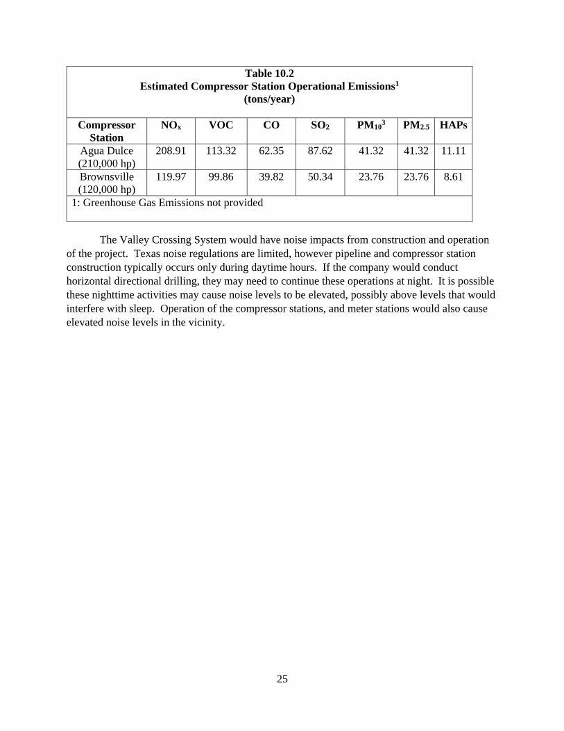
The compressor station operators have received air quality permits from the TCEQ for the Valley Crossing System compressor stations located at Agua Dulce and Brownsville. We contacted the TCEQ and received the permit and emissions information. Other sources of operational emissions, such as fugitive methane emissions, emissions from any line heaters, boilers, etc. were not provided.
25
Table 10.2 Estimated Compressor Station Operational Emissions1
(tons/year)
Compressor Station
NOx VOC CO SO2 PM103 PM2.5 HAPs
Agua Dulce (210,000 hp)
208.91 113.32 62.35 87.62 41.32 41.32 11.11
Brownsville (120,000 hp)
119.97 99.86 39.82 50.34 23.76 23.76 8.61
1: Greenhouse Gas Emissions not provided
The Valley Crossing System would have noise impacts from construction and operation of the project. Texas noise regulations are limited, however pipeline and compressor station construction typically occurs only during daytime hours. If the company would conduct horizontal directional drilling, they may need to continue these operations at night. It is possible these nighttime activities may cause noise levels to be elevated, possibly above levels that would interfere with sleep. Operation of the compressor stations, and meter stations would also cause elevated noise levels in the vicinity.
26
C. ALTERNATIVES
In accordance with NEPA and Commission policy, we considered the No-Action Alternative as discussed below and sought to identify and evaluate reasonable alternatives to the Project. Our evaluation criteria included whether the alternatives would: 1) provide a significant environmental advantage over the Project; 2) meet the Project’s stated objectives; and 3) be technically and economically feasible and practical.
Implementing the No-Action Alternative would result in the proposed Project not being constructed. Not constructing the Project would avoid affecting the environment as described previously in this document. However, the objective of the Project would not be met and the demand for natural gas in Mexico would not be satisfied. Ultimately, the facilities proposed by the Project are simply an interconnection between two non-jurisdictional facilities that are already sited. If the Project were not constructed, then the operators of the non-jurisdictional systems would find an alternative interconnection mode. These alternatives would result in their own set of specific environmental impacts that could be equal to or greater than those described for the current proposal.
Valley Crossing selected the siting of the proposed Project to traverse the shortest distance necessary to interconnect the two non-jurisdictional pipelines. No substantial adverse impacts were identified during scoping or in our analysis of the Project. Therefore, we did not identify any crossing location or other alternatives that could provide a significant environmental advantage over the Project as proposed, and we identified no alternatives that could satisfy all three of our evaluation criteria. In summary, we have determined that the proposed Project, as modified by our recommended mitigation measures, is the preferred alternative that can meet the Project objectives.
27
D. CONCLUSIONS AND RECOMMENDATIONS
Based on our analysis as described in this EA and Valley Crossing’s implementation of our recommendations, we conclude that approval of this Project would not constitute a major federal action significantly affecting the quality of the human environment. Therefore, we recommend that the Commission Order contain a finding of no significant impact and include the measures listed below as conditions to any authorization the Commission may issue.
1. Valley Crossing shall follow the construction procedures and mitigation measures described in its application and supplements, including responses to staff data requests, as identified in the EA, unless modified by the Order. Valley Crossing must:
a. request any modification to these procedures, measures, or conditions in a filing with the Secretary;
b. justify each modification relative to site-specific conditions; c. explain how that modification provides an equal or greater level of environmental
protection than the original measure; and d. receive approval in writing from the Director of the Office of Energy Projects (OEP)
before using that modification.
2. The Director of OEP has delegated authority to take whatever steps are necessary to ensure the protection of all environmental resources during activities associated with the construction and operation of the project. This authority shall allow:
a. the modification of conditions of the Order; and b. the design and implementation of any additional measures deemed necessary
(including stop work authority) to ensure continued compliance with the intent of the environmental conditions as well as the avoidance or mitigation of adverse environmental impact resulting from project construction and operation.
3. Prior to any construction, Valley Crossing shall file an affirmative statement with the Secretary, certified by a senior company official, that all company personnel, environmental inspectors, and contractor personnel will be informed of the EI’s authority and have been or will be trained on the implementation of the environmental mitigation measures appropriate to their jobs before becoming involved with construction and restoration activities.
4. The authorized facility locations shall be as shown in the EA, as supplemented by filed alignment sheets. As soon as they are available, and before the start of construction, Valley Crossing shall file with the Secretary any revised detailed survey alignment maps/sheets at a scale not smaller than 1:6,000 with station positions for all facilities approved by the Order. All requests for modifications of environmental conditions of the Order or site-specific clearances must be written and must reference locations designated on these alignment maps/sheets.
5. Valley Crossing shall file with the Secretary detailed alignment maps/sheets and aerial photographs at a scale not smaller than 1:6,000 identifying all route realignments or facility relocations, and staging areas, pipe storage yards, new access roads, and other areas that would be used or disturbed and have not been previously identified in filings with the Secretary. Approval for each of these areas must be explicitly requested in
28
writing. For each area, the request must include a description of the existing land use/cover type, documentation of landowner approval, whether any cultural resources or federally listed threatened or endangered species would be affected, and whether any other environmentally sensitive areas are within or abutting the area. All areas shall be clearly identified on the maps/sheets/aerial photographs. Each area must be approved in writing by the Director of OEP before construction in or near that area.
This requirement does not apply to extra workspace allowed by the Commission’s Upland Erosion Control, Revegetation, and Maintenance Plan, minor field realignments per landowner needs, and requirements that do not affect other landowners or sensitive environmental areas such as wetlands.
Examples of alterations requiring approval include all route realignments and facility location changes resulting from:
a. implementation of cultural resources mitigation measures; b. implementation of endangered, threatened, or special concern species mitigation
measures; c. recommendations by state regulatory authorities; and d. agreements with individual landowners that affect other landowners or could
adversely affect sensitive environmental areas.
6. At least 60 days before construction begins, Valley Crossing shall file an Implementation Plan with the Secretary for review and written approval by the Director of OEP. Valley Crossing must file revisions to the plan as schedules change. The plan shall identify:
a. how Valley Crossing will implement the construction procedures and mitigation measures described in its application and supplements (including responses to staff environmental information requests), identified in the EA, and required by the Order;
b. how Valley Crossing will incorporate these requirements into the contract bid documents, construction contracts (especially penalty clauses and specifications), and construction drawings so that the mitigation required at each site is clear to onsite construction and inspection personnel;
c. company personnel, including EIs and contractors, who will receive copies of the appropriate material;
d. the location and dates of the environmental compliance training and instructions Valley Crossing will give to all personnel involved with construction and restoration (initial and refresher training as the project progresses and personnel change),
e. the company personnel (if known) and specific portion of Valley Crossing’s organization having responsibility for compliance;
f. the procedures (including use of contract penalties) Valley Crossing will follow if noncompliance occurs; and
g. for each discrete facility, a Gantt or PERT chart (or similar project scheduling diagram), and dates for: (1) the completion of all required surveys and reports; (2) the environmental compliance training of onsite personnel; (3) the start of construction; and (4) the start and completion of restoration.
29
7. Valley Crossing shall employ at least one EI for the Project. The EI shall be:
a. responsible for monitoring and ensuring compliance with all mitigation measures required by the Order and other grants, permits, certificates, or other authorizing documents;
b. responsible for evaluating the construction contractor's implementation of the environmental mitigation measures required in the contract (see condition 6 above) and any other authorizing document;
c. empowered to order correction of acts that violate the environmental conditions of the Order, and any other authorizing document;
d. responsible for documenting compliance with the environmental conditions of the Order, as well as any environmental conditions/permit requirements imposed by other federal, state, or local agencies; and
e. responsible for maintaining status reports.
8. Beginning with the filing of its Implementation Plan, Valley Crossing shall file updated status reports with the Secretary on a biweekly basis until all construction and restoration activities are complete. On request, these status reports will also be provided to other federal and state agencies with permitting responsibilities. Status reports shall include:
a. an update on Valley Crossing’s efforts to obtain the necessary federal authorizations; b. the construction status of the project, work planned for the following reporting period,
and any schedule changes for stream crossings or work in other environmentally-sensitive areas;
c. a listing of all problems encountered and each instance of noncompliance observed by the EI during the reporting period (both for the conditions imposed by the Commission and any environmental conditions/permit requirements imposed by other federal, state, or local agencies);
d. a description of the corrective actions implemented in response to all instances of noncompliance, and their cost.
e. the effectiveness of all corrective actions implemented; f. a description of any landowner/resident complaints that may relate to compliance
with the requirements of the Order, and the measures taken to satisfy their concerns; and
g. copies of any correspondence received by Valley Crossing from other federal, state, or local permitting agencies concerning instances of noncompliance, and Valley Crossing’s response.
9. Prior to receiving written authorization from the Director of OEP to commence construction of any Project facilities, Valley Crossing shall file with the Secretary documentation that it has received all applicable authorizations required under federal law (or evidence of wavier thereof).
10. Valley Crossing must receive written authorization from the Director of OEP before placing the Project into service. Such authorization will only be granted following a determination that rehabilitation and restoration of the right-of-way and other areas affected by the Project are proceeding satisfactorily.
11. Within 30 days of placing the authorized facilities in service, Valley Crossing shall file an affirmative statement with the Secretary, certified by a senior company official:
30
a. that the facilities have been constructed and installed in compliance with all applicable conditions, and that continuing activities will be consistent with all applicable conditions; or
b. identifying which of the conditions in the Order Valley Crossing has complied with or will comply with. This statement shall also identify any areas affected by the Project where compliance measures were not properly implemented, if not previously identified in filed status reports, and the reason for noncompliance.
12. Valley Crossing shall not begin construction activities until: a. the staff receives comments from the NMFS regarding the proposed action; and b. Valley Crossing has received written notification from the Director of OEP that
construction or use of mitigation may begin.
13. Valley Crossing shall not begin construction of facilities until:
a. Valley Crossing files with the Secretary: (1) documentation that Valley Crossing contacted and provided project details to the
appropriate federally recognized tribes (Tribes) for comments; (2) copies of all correspondence with Tribes and resulting documentation; (3) remaining cultural resources survey report(s) and addendum(s); (4) site evaluation report(s) and avoidance/treatment plan(s), as required; and (5) comments on the cultural resources reports, addendums, and plans from the
Texas State Historic Preservation Officer.
b. the Advisory Council on Historic Preservation is afforded an opportunity to comment if historic properties would be adversely affected; and
c. the FERC staff reviews and the Director of OEP approves the cultural resources reports and plans, and notifies Valley Crossing in writing that treatment plans/mitigation measures (including archaeological data recovery) may be implemented and/or construction may proceed.
All materials filed with the Commission containing location, character, and ownership information about cultural resources must have the cover and any relevant pages therein clearly labeled in bold lettering: “CUI//PRIV - DO NOT RELEASE.”
Appendix A
TECHNICAL MEMORANDUM DATE: May 1, 2017 TO: Mr. Rio Franzman SWCA Environmental Consultants FROM: Lee Beshoner, PE and Ranjit Jadhav, PhD FTN Associates, Ltd. Firm Registration No: F-02550 SUBJECT: Border Crossing Pipeline Sediment Plume Modeling
FTN No. R11659-1600-001 1.0 INTRODUCTION At the request of SWCA Environmental Consultants (SWCA), FTN Associates, Ltd. (FTN) has performed numerical sediment transport modeling analysis for the Border Crossing Pipeline Project (the Project). The project consists of a segment of 42-inch diameter pipe that extends 1,000 feet in the Gulf of Mexico in Texas state waters to the International Boundary between the United States and Mexico (VCP, 2016). The Project is location is shown Figure 1. The primary source of sediment release considered is the jetted trenching operation for pipeline burial.
2.0 PURPOSE The purpose of the study is to model transport of the sediment plume emanating from the trenching operation during placement of a pipeline segment on the seafloor. There are two specific objectives as follows:
Estimate the thickness and acreage of sediment deposition on the seafloor; and
Estimate the size, duration, and spatial migration of the sediment plume ejected during the jetting operations.
3.0 STUDY AREA The study area is part of the open water off the coast of south Texas. The hydrodynamics of the system are driven by tides and winds in the Gulf of Mexico. The depth at the project location is approximately 90 ft.
20170502-5169 FERC PDF (Unofficial) 5/2/2017 3:33:19 PM
Mr. Rio Franzman May 1, 2017 Page 2
4.0 METHODOLOGY FTN developed and applied Delft3D model version 4.02.03 (Deltares, 2016) to predict the tidal circulation and the transport of suspended sediment. The Delft3D model simulates water levels and velocities driven by boundary conditions of tides and currents. Concurrently, it also simulates transport of suspended sediment particles and calculates the thickness of the deposited sediments. It has been applied in several sediment plume and deposition model studies around the world (e.g. Dunn, et al., 2015). The Delft3D FLOW module utilizes a robust numerical finite-difference scheme where model results are computed on a horizontal staggered grid. The water level points are designated in the center of a continuity cell and the velocity components are perpendicular to the grid cell faces. Delft3D can be operated in a two-dimensional (2D) (vertically averaged) or a three-dimensional (3D) mode. In 3D mode, the model uses the sigma-coordinate system. The sigma-coordinate system is a variable layer-thickness modeling system. This means that, over the entire computational area, irrespective of the local water depth, the number of layers is constant. As a result, a smooth representation of the bathymetry is obtained. Also, as opposed to fixed vertical grid size 3D models, the full definition of the 3D layering system is maintained into shallow water until the computational point is dried. Vertical turbulence closure in Delft3D is based on the eddy viscosity concept. Delft3D simulates sediment as a scalar transport term in the governing equations and allows the modeling of suspended sediment in the water column as well as the bed load transport. It also offers the capability for bed morphology modeling by tracking the change in bed level through time and space. Due to the expedited schedule, the modeling study is based on existing information and data available to FTN. No field topographic surveys, measurements of water levels, velocities, or suspended sediment concentrations were carried out to support the results of this study. All supporting data were obtained from public sources or were provided by SWCA. The simulations were performed under "normal" hydrodynamic and meteorological conditions. Again, due to time constraints, no statistical analyses were performed to develop parameters (e.g., tide levels, wind, currents) that are statistically "normal". Instead, available tidal and wind data were used that were deemed normal. 5.0 STUDY ASSUMPTIONS AND LIMITATIONS The following assumptions and limitations apply to this study: It is assumed that the trenching device captures all the dredged sediment from the trench
and releases it in the open water at approximately 12 ft above the seafloor.
20170502-5169 FERC PDF (Unofficial) 5/2/2017 3:33:19 PM
Mr. Rio Franzman May 1, 2017 Page 3
The sediment grain size distribution from one sample at the project site is assumed to apply to the entire length of the modeled trench segment.
As the fine sand and silt-clay constitutes majority of the sediment, the coarser fraction and gravel is not modeled and is assumed to deposit almost immediately close to the trench.
Representing the trench itself in the model bathymetry was not necessary for the computations so it is not represented in the model. The sediment deposition depth that is calculated along the trench is referenced to the original seafloor elevation.
Only the statistically significant wind speed and direction are considered in the analysis. Sediment plume migration may have a different trajectory under other wind conditions, especially other wind directions.
The predicted suspended sediment concentration applies outside the initial rapid mixing zone occurring at the release point.
The ambient suspended sediment concentration is assumed to be insignificant due to the lack of available observed data.
6.0 MODEL DEVELOPMENT AND INPUTS 6.1 Grid and Bathymetry The model domain is shown in Figure 2. It is approximately 9 miles alongshore and extends 14 miles eastwards with depths varying from 5 ft near the coastline to about 120 ft offshore. The model domain size was selected such that the boundary conditions are specified far away from the area of interest. The domain is represented by a 3D computational grid. The grid is most refined (cell size 14 m) near the sediment source where rapid variations in sediment concentration are expected and becomes coarser (cell size 400 m) towards the boundary. The grid has 20 layers in the vertical direction. The bathymetry was obtained from the Texas Natural Resources Information System (TNRIS) v0-1 database. (https://tnris.org/data-catalog/entry/bathymetry-tx-coast-v0-1/) and interpolated on a 100 m grid in the UTM (WGS184 for horizontal) coordinate system. This database for the Louisiana-Texas coastal shelf is a collection of about 3.5 million soundings from 300 historic hydrographic surveys conducted between 1930 and 2005 by the National Oceanic and Atmospheric Agency’s Office (NOAA) of Coast Survey and is available from the NOAA National Geophysical Data Center. The vertical datum of this dataset is unknown and is assumed to be Mean Sea Level (MSL) for this study.
20170502-5169 FERC PDF (Unofficial) 5/2/2017 3:33:19 PM
Mr. Rio Franzman May 1, 2017 Page 4
6.2 Hydraulic Boundary Conditions Hydraulic boundary conditions are tidal water levels specified at the offshore boundary of the model domain. There is no known water level data buoy west of the model domain. Ideally, a much larger tidal circulation model would have been developed to provide boundary conditions for the model domain. However, due to time constraints, water level data from NOAA Station 8779749 (Brazos, Santiago) (Figure 2) were utilized instead. The applied tidal boundary conditions are shown in Figure 3. All water surface elevation data are referenced to MSL.
6.3 Meteorological Wind Forcing Meteorological wind forcing was represented in the model by specifying a constant wind speed and direction over the simulation period. The wind data is obtained from the US Army Corps of Engineers (USACE) Wave Information System (WIS) Station 73017. The annual wind rose at this station is shown in Figure 4. Two cases of wind conditions were simulated, namely, a Normal Wind Case with a wind speed of 7.5 m/s (14.6 knots) and a High Wind Case with a wind speed of 15 m/s (29.2 knots). For both cases, the wind direction was selected to be 135o out of the southeast based on the dominant direction observed in the wind rose. The annual wind rose includes seasonal wind variations.
6.4 Sediment Source Characteristics The sediment released from the trenching operation is determined to be a mix of 67% fine sand (Mean diameter, D50=0.018 mm) and 23% silt-clay based on the field vibrocore sample VC_V (REV) collected at the site (Fugro, 2016). This sample was taken near the US-Mexico border. The sediment has been described to be clayey fine sand from the seafloor to the maximum explored depth of about 9 ft below seafloor. Figure 5 shows grain-size distribution at this location. Additionally, SWCA provided the following characteristics of the trenching devices that were used in determining the mass rate of sediment release:
Volume of sand being jet-dredged = 5.2 yd3/ft = 140.4 ft3/ft Forward speed of the device = 3 ft/min
This results in volumetric rate of dredging of 421.2 ft3/min (0.2 m3/s). The sediment is ejected in the water column approximately 12 ft above the seafloor.
20170502-5169 FERC PDF (Unofficial) 5/2/2017 3:33:19 PM
Mr. Rio Franzman May 1, 2017 Page 5
6.5 Model Input Coefficients Model coefficients specified for simulations are as follows: Horizontal and vertical eddy viscosities and diffusivities were set to 1.0 m2/s and
1.0x10⁻⁶ m2/s, respectively.
Bed roughness was specified by using Manning's n of 0.025.
Settling velocity was set at 0.25 mm/s for the cohesive fraction of the sediment.
Wind drag coefficient, Cd, was assumed to vary linearly with wind speed from 0.00063 to 0.00723 over the range of U10 = 0–100 m/s.
6.6 Model Time Parameters Model simulation was carried out for 144 hours (6 days) starting from January 1, 2017, 00:00. The model time-step was set to 1 min during the active sediment release period and then to 2 min for the remainder of the simulation period.
7.0 MODEL CALIBRATION A model calibration is a process where the model results are compared with known measurements of water levels and velocities. A model is calibrated to increase confidence in its results. Since there are no dedicated monitoring gauges installed or available to calibrate the model to, a complete calibration was not possible. To asses overall performance of the model, the predicted velocities were compared with those observed at a nearby NOAA TGLO TABS Buoy (J) 42044 by a velocity or current rose analysis. The velocity is the primary driver of sediment plume migration. Figure 6 shows the predicted and observed current roses. It can be seen that the overall current directions predicted by the model are consistent with those observed at the nearby NOAA Station 42044. The predicted current direction is also consistent with such measurements reported in the literature along lower Texas coast (e.g. Smith, 1980). The median observed current was 15.3 cm/s while the model predicted currents of 16.5 cm/s and 52.2 cm/s under normal and high wind conditions, respectively.
8.0 MODEL SCENARIO SETUP The sediment release simulated in the model corresponds to a trenching operation along the pipeline alignment that is made up two segments (Figure 7). Segment BC is the 1,000 ft segment that is in the FERC jurisdictional zone. Segment AB is the adjoining non-jurisdictional segment, with an arbitrary length of 0.9 mi. Segment AB was simulated to account for the potential contribution of sediment from trenching outside the jurisdictional segment. The trenching operation sediment release started at Location A. The sediment source continued
20170502-5169 FERC PDF (Unofficial) 5/2/2017 3:33:19 PM
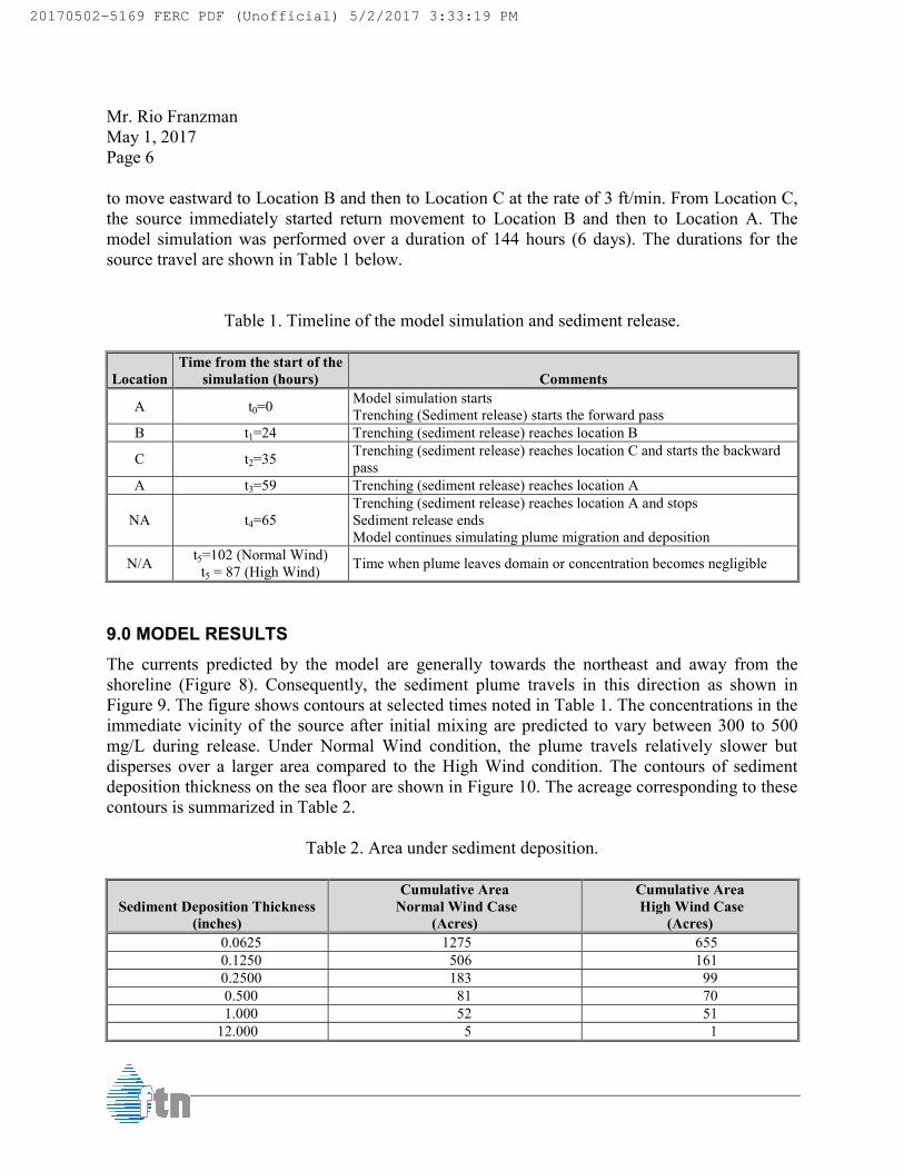
Mr. Rio Franzman May 1, 2017 Page 6
to move eastward to Location B and then to Location C at the rate of 3 ft/min. From Location C, the source immediately started return movement to Location B and then to Location A. The model simulation was performed over a duration of 144 hours (6 days). The durations for the source travel are shown in Table 1 below.
Table 1. Timeline of the model simulation and sediment release.
Location Time from the start of the
simulation (hours) Comments
A t0=0 Model simulation starts Trenching (Sediment release) starts the forward pass
B t1=24 Trenching (sediment release) reaches location B
C t2=35 Trenching (sediment release) reaches location C and starts the backward pass
A t3=59 Trenching (sediment release) reaches location A
NA t4=65 Trenching (sediment release) reaches location A and stops Sediment release ends Model continues simulating plume migration and deposition
N/A t5=102 (Normal Wind) t5 = 87 (High Wind) Time when plume leaves domain or concentration becomes negligible
9.0 MODEL RESULTS The currents predicted by the model are generally towards the northeast and away from the shoreline (Figure 8). Consequently, the sediment plume travels in this direction as shown in Figure 9. The figure shows contours at selected times noted in Table 1. The concentrations in the immediate vicinity of the source after initial mixing are predicted to vary between 300 to 500 mg/L during release. Under Normal Wind condition, the plume travels relatively slower but disperses over a larger area compared to the High Wind condition. The contours of sediment deposition thickness on the sea floor are shown in Figure 10. The acreage corresponding to these contours is summarized in Table 2.
Table 2. Area under sediment deposition.
Sediment Deposition Thickness (inches)
Cumulative Area Normal Wind Case
(Acres)
Cumulative Area High Wind Case
(Acres) 0.0625 1275 655 0.1250 506 161 0.2500 183 99 0.500 81 70 1.000 52 51
12.000 5 1
20170502-5169 FERC PDF (Unofficial) 5/2/2017 3:33:19 PM
Mr. Rio Franzman May 1, 2017 Page 7 The thickness of sediment deposition along the shown in Figure 11. Note that the model bathymetry does not include actual trench, so the sediment thickness is referenced above the original seafloor. We appreciate the opportunity to work with you on this project. If you have any questions or comments regarding this project, please do not hesitate to contact Ranjit Jadhav, PhD, at (225) 766 LJB/tas R:\TRANSFER\RSJ\2017-05-01 TM-R FRANZMAN BORDER CROSSING PIPELINE SEDIMENT PLUME MODELINGBORDER CROSSING PIPELINE SEDIMENT PLUME MODE
The thickness of sediment deposition along the approximate centerline trajectory of Note that the model bathymetry does not include actual trench, so the
sediment thickness is referenced above the original seafloor.
We appreciate the opportunity to work with you on this project. If you have any questions or comments regarding this project, please do not hesitate to contact me at (479) 571
766-0586.
R FRANZMAN BORDER CROSSING PIPELINE SEDIMENT PLUME MODELING\2017-05-01 TMBORDER CROSSING PIPELINE SEDIMENT PLUME MODELING\2017-05-01 TM-R FRANZMAN.DOCX
trajectory of the plume is Note that the model bathymetry does not include actual trench, so the
We appreciate the opportunity to work with you on this project. If you have any questions or me at (479) 571-3334 or
01 TM-R FRANZMAN
20170502-5169 FERC PDF (Unofficial) 5/2/2017 3:33:19 PM

Mr. Rio Franzman May 1, 2017 Page 8
10.0 REFERENCES Deltares. 2016. Hydro-morphodynamics: Delft3D Flow User Manual. Deltares, the Netherlands. Dunn et al (2015) Hydrodynamic and Sediment Modelling within a Micro Tidal Estuary: Port
Curtis Estuary, Australia. J. Mar. Sci. Eng., 3, 720-744. FUGRO. 2016. Geotechnical Data Report, Offshore Geophysical and Geotechnical Survey,
Valley Crossing Pipeline Project, South Padre Island Area, Offshore Gulf of Mexico, Texas. Fugro Marine Geoservices, Inc.
Smith, N.P (1980). Temporal and Spatial Variability in Longshore Motion Along the Texas Gulf Coast. J. Geophy. Res., 85, 1531-1536.
VCP (2016) Application for Section 3 Authorization and Presidential Permit, Border Crossing Project, Texas. Valley Crossing Pipeline, LLC.
20170502-5169 FERC PDF (Unofficial) 5/2/2017 3:33:19 PM
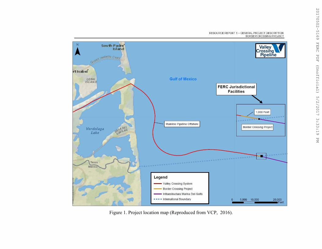
Figure 1. Project location map (Reproduced from VCP, 2016).
20170502-5169 FERC PDF (Unofficial) 5/2/2017 3:33:19 PM
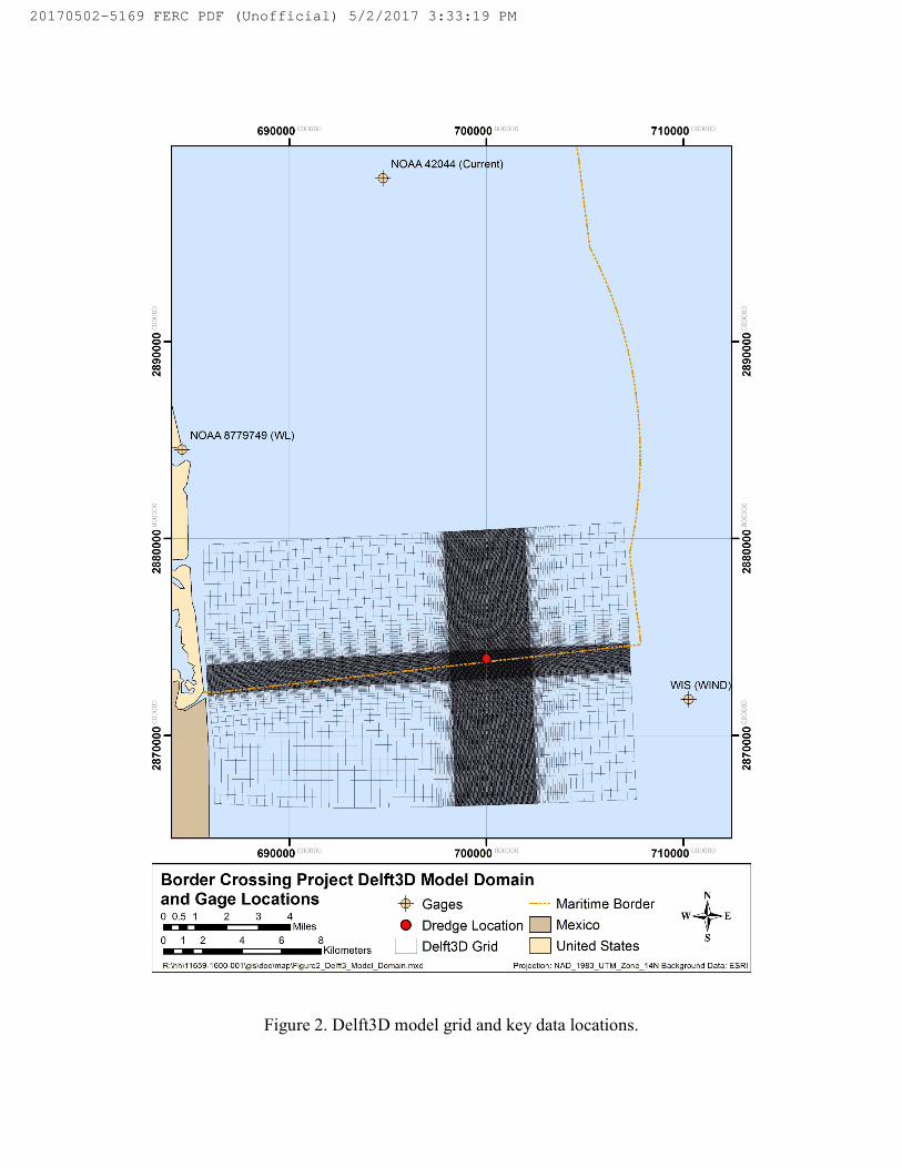
Figure 2. Delft3D model grid and key data locations.
20170502-5169 FERC PDF (Unofficial) 5/2/2017 3:33:19 PM
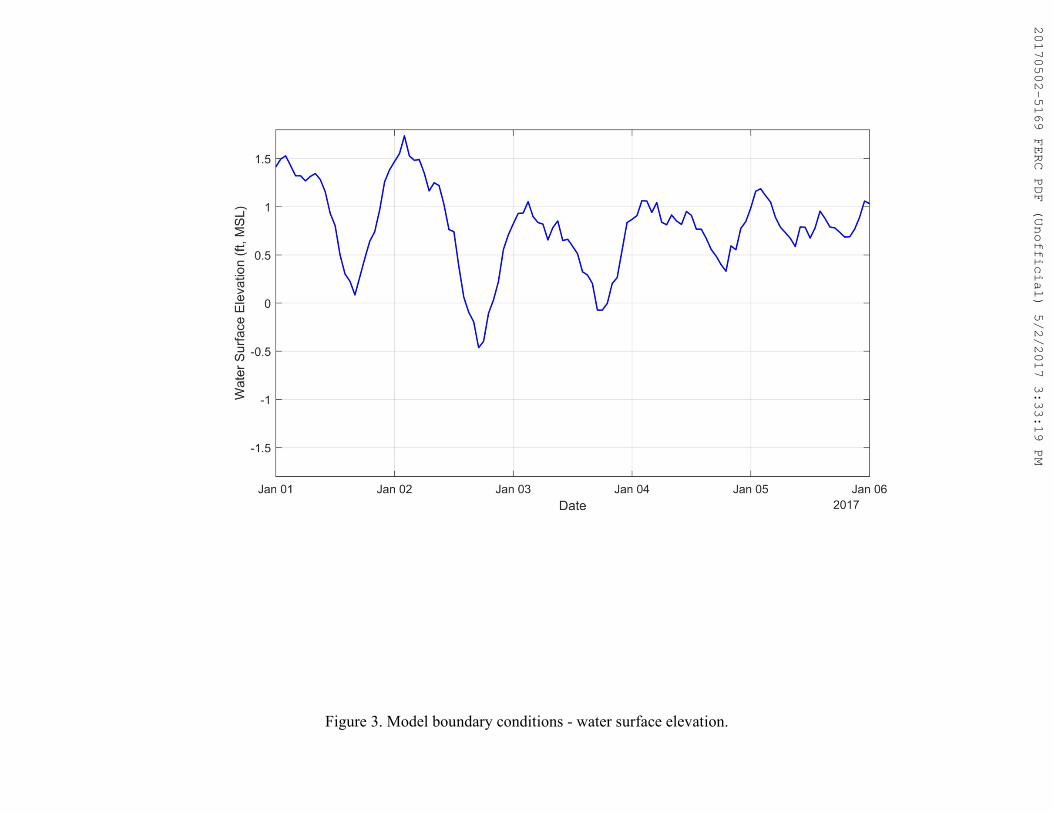
Figure 3. Model boundary conditions - water surface elevation.
20170502-5169 FERC PDF (Unofficial) 5/2/2017 3:33:19 PM
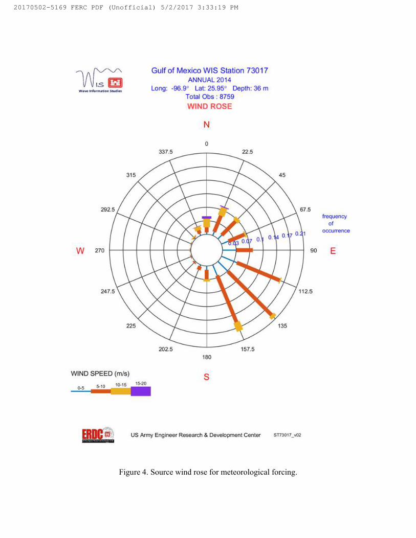
Figure 4. Source wind rose for meteorological forcingSource wind rose for meteorological forcing.
20170502-5169 FERC PDF (Unofficial) 5/2/2017 3:33:19 PM

Figure 5. Grain-size distribution curve at VC_V(REV) (Reproduced from Fugro 2016).
20170502-5169 FERC PDF (Unofficial) 5/2/2017 3:33:19 PM
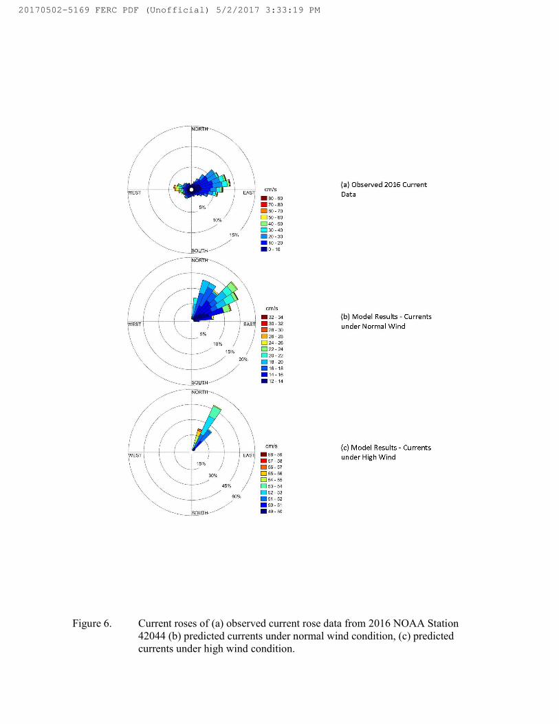
Figure 6. Current roses of (a) observed current rose data from 2016 NOAA Station 42044 (b) predicted currents under normal wind condition, (c) predicted currents under high wind condition.
20170502-5169 FERC PDF (Unofficial) 5/2/2017 3:33:19 PM
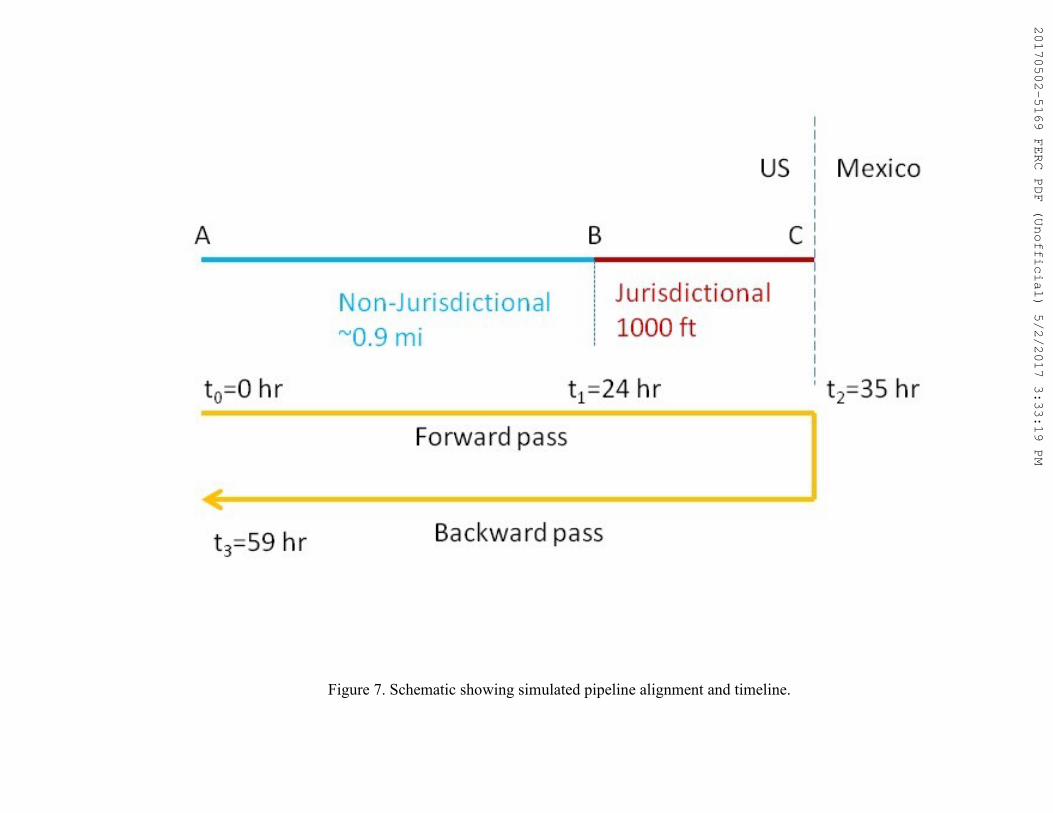
Figure 7. Schematic showing simulated pipeline alignment and timeline.
20170502-5169 FERC PDF (Unofficial) 5/2/2017 3:33:19 PM
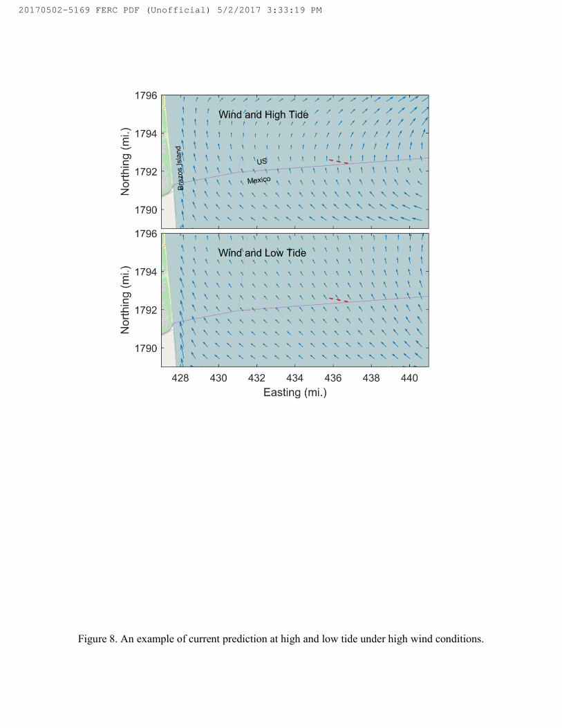
Figure 8. An example of current prediction at high and low tide under high wind conditions.
20170502-5169 FERC PDF (Unofficial) 5/2/2017 3:33:19 PM
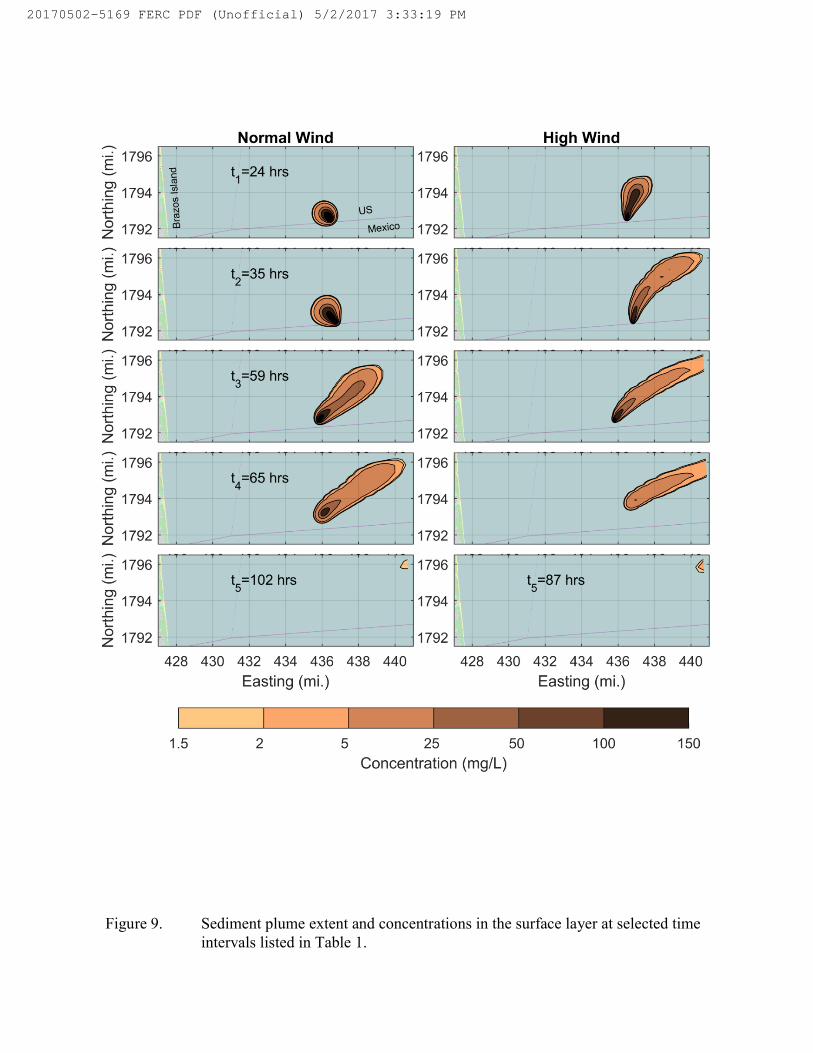
Figure 9. Sediment plume extent and concentrations in the surface layer at selected time intervals listed in Table 1.
20170502-5169 FERC PDF (Unofficial) 5/2/2017 3:33:19 PM
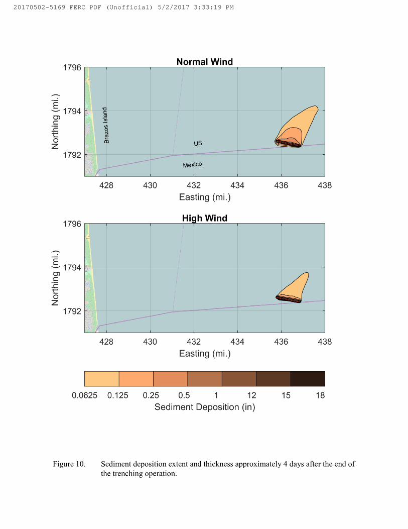
Figure 10. Sediment deposition extent and thickness approximately 4 days after the end of the trenching operation.
20170502-5169 FERC PDF (Unofficial) 5/2/2017 3:33:19 PM
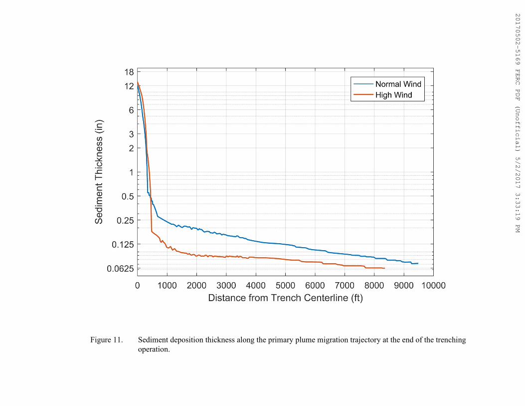
Figure 11. Sediment deposition thickness along the primary plume migration trajectory at the end of the trenching operation.
20170502-5169 FERC PDF (Unofficial) 5/2/2017 3:33:19 PM
Attachment 2
Cable Sweep Diagram
20170502-5169 FERC PDF (Unofficial) 5/2/2017 3:33:19 PM
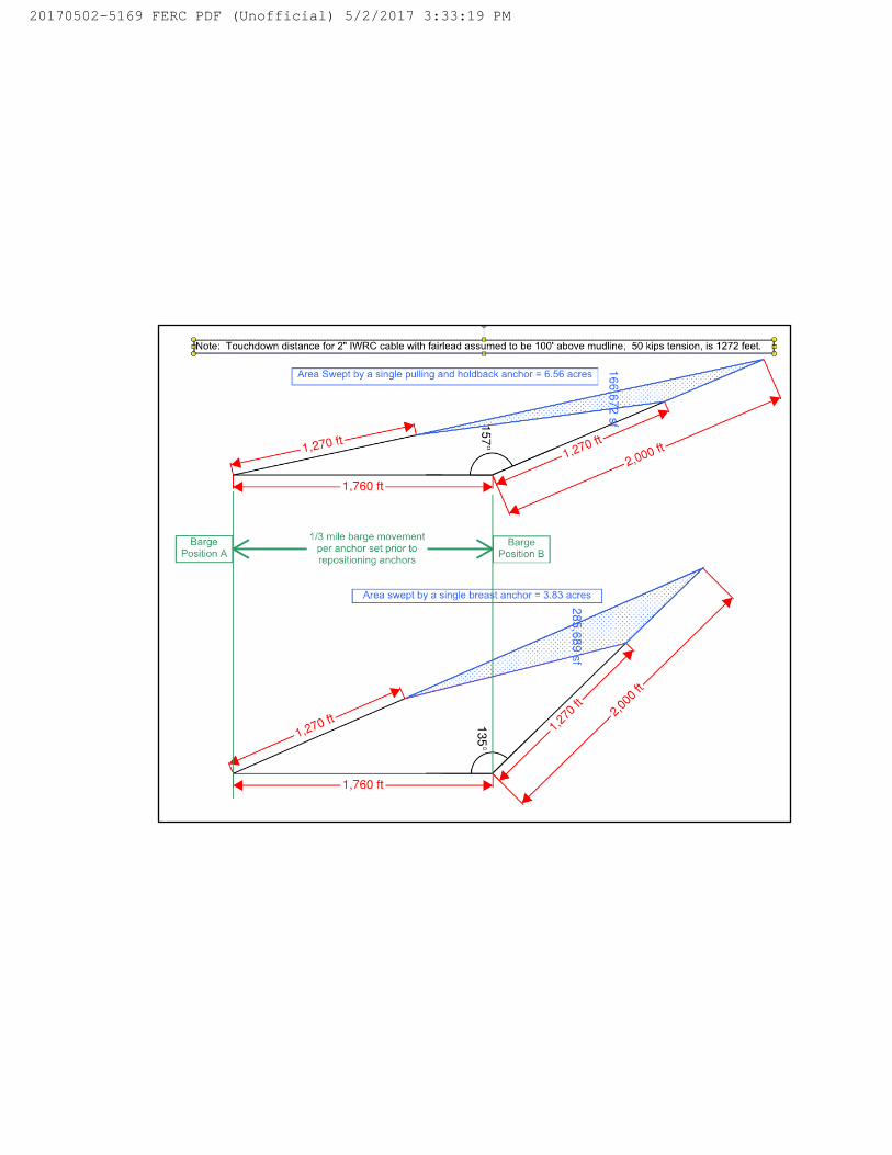
20170502-5169 FERC PDF (Unofficial) 5/2/2017 3:33:19 PM
Appendix B
LIST OF PREPARERS
Peconom, John – Project Manager; Proposed Action, Environmental Analysis; and Alternatives B.S. Environmental Biology & Management, University of California at Davis
Howard, Eric – Cultural Resources M.A., Anthropology, University of Tennessee B.A., Anthropology, University of Tennessee
Tomasi, Eric – Resources Specialist, Air Quality and Noise, Reliability and Pipeline Safety B.S. Aerospace Engineering, Boston University