bmp 6.4.1: pervious pavement with infiltration bed · 2017-06-30 · pervious concrete should...
TRANSCRIPT

Pennsylvania Stormwater Best Management Practices Manual Chapter 6
BMP 6.4.1: Pervious Pavement with Infiltration Bed
Pervious pavement consists of a permeable surface course underlain by a uniformly-graded stone bed which provides temporary storage for peak rate control and promotes infiltration. The surface course may consist of porous asphalt, porous concrete, or various porous structural pavers laid on uncompacted soil.
Key Design Elements Potential Applications
Residential: Commercial: Ultra Urban:
Industrial: Retrofit:
Highway/Road:
Limited Yes Yes Yes Yes Limited
Stormwater Functions
Volume Reduction: Recharge:
Peak Rate Control: Water Quality:
Medium Medium Medium Medium
Water Quality Functions
TSS: TP:
NO3:
85% 85% 30%
· Almost entirely for peak rate control
· Water quality and quantity are not addressed
· Short duration storage; rapid restoration of primary uses
· Minimize safety risks, potential property damage, and user inconvenience
· Emergency overflows
· Maximum ponding depths
· Flow control structures
· Adequate surface slope to outlet
Other Considerations
• Protocol 1. Site Evaluation and Soil Infiltration Testing and Protocol 2. Infiltration Systems
Guidelines should be followed, see Appendix C
363-0300-002 / December 30, 2006 Page 7 of 257

Pennsylvania Stormwater Best Management Practices Manual Chapter 6
Description A pervious pavement bed consists of a pervious surface course underlain by a stone bed of uniformly graded and clean-washed coarse aggregate, 1-1/2 to 2-1/2 inches in size, with a void space of at least 40%. The pervious pavement may consist of pervious asphalt, pervious concrete, or pervious pavement units. Stormwater drains through the surface, is temporarily held in the voids of the stone bed, and then slowly drains into the underlying, uncompacted soil mantle. The stone bed can be designed with an overflow control structure so that during large storm events peak rates are controlled, and at no time does the water level rise to the pavement level. A layer of geotextile filter fabric separates the aggregate from the underlying soil, preventing the migration of fines into the bed. The bed bottoms should be level and uncompacted. If new fill is required, it should consist of additional stone and not compacted soil.
Pervious pavement is well suited for parking lots, walking paths, sidewalks, playgrounds, plazas, tennis courts, and other similar uses. Pervious pavement can be used in driveways if the homeowner is aware of the stormwater functions of the pavement. Pervious pavement roadways have seen wider application in Europe and Japan than in the U.S., although at least one U.S. system has been constructed . In Japan and the U.S., the application of an open-graded asphalt pavement of 1” or less on roadways has been used to provide lateral surface drainage and prevent hydroplaning, but these are applied over impervious pavement on compacted sub-grade. This application is not pervious pavement. Properly installed and maintained pervious pavement has a significant life-span, and existing systems that are more than twenty years in age continue to function. Because water drains through the surface
363-0300-002 / December 30, 2006 Page 8 of 257

Pennsylvania Stormwater Best Management Practices Manual Chapter 6
course and into the subsurface bed, freeze-thaw cycles do not tend to adversely affect pervious pavement. Pervious pavement is most susceptible to failure difficulties during construction, and therefore it is important that the construction be undertaken in such as way as to prevent:
• Compaction of underlying soil • Contamination of stone subbase with sediment and fines • Tracking of sediment onto pavement • Drainage of sediment laden waters onto pervious surface or into constructed bed
Staging, construction practices, and erosion and sediment control must all be taken into consideration when using pervious pavements. Studies have shown that pervious systems have been very effective in reducing contaminants such as total suspended solids, metals, and oil and grease. When designed, constructed, and maintained according to the following guidelines, pervious pavement with underlying infiltration systems can dramatically reduce both the rate and volume of runoff, recharge the groundwater, and improve water quality. In northern climates, pervious pavements have less of a tendency to form black ice and often require less plowing. Winter maintenance is described on page 17. Pervious asphalt and concrete surfaces provide better traction for walking paths in rain or snow conditions. Variations Pervious Bituminous Asphalt Early work on pervious asphalt pavement was conducted in the early 1970’s by the Franklin Institute in Philadelphia and consists of standard bituminous asphalt in which the fines have been screened and reduced, allowing water to pass through small voids. Pervious asphalt is placed directly on the stone subbase in a single 3 ½ inch lift that is lightly rolled to a finish depth of 2 ½ inches. Because pervious asphalt is standard asphalt with reduced fines, it is similar in appearance to standard asphalt. Recent research in open-graded mixes for highway application has led to additional improvements in pervious asphalt through the use of additives and higher-grade binders. Pervious asphalt is suitable for use in any climate where standard asphalt is appropriate.
363-0300-002 / December 30, 2006 Page 9 of 257

Pennsylvania Stormwater Best Management Practices Manual Chapter 6
Pervious Concrete Pervious Portland Cement Concrete, or pervious concrete, was developed by the Florida Concrete Association and has seen the most widespread application in Florida and southern areas. Like pervious asphalt, pervious concrete is produced by substantially reducing the number of fines in the mix in order to establish voids for drainage. In northern and mid-Atlantic climates such as Pennsylvania, pervious concrete should always be underlain by a stone subbase designed for stormwater management and should never be placed directly onto a soil subbase. While pervious asphalt is very similar in appearance to standard asphalt, pervious concrete has a coarser appearance than its conventional counterpart. Care must be taken during placement to avoid working the surface and creating an impervious layer. Pervious concrete has been proven to be an effective stormwater management BMP. Additional information pertaining to pervious concrete, including specifications, is available from the Florida Concrete Association and the National Ready Mix Association.
363-0300-002 / December 30, 2006 Page 10 of 257
Pennsylvania Stormwater Best Management Practices Manual Chapter 6
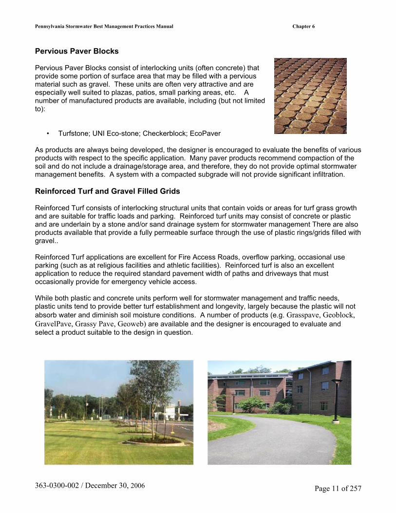
Pervious Paver Blocks Pervious Paver Blocks consist of interlocking units (often concrete) that provide some portion of surface area that may be filled with a pervious material such as gravel. These units are often very attractive and are especially well suited to plazas, patios, small parking areas, etc. A number of manufactured products are available, including (but not limited to):
• Turfstone; UNI Eco-stone; Checkerblock; EcoPaver
As products are always being developed, the designer is encouraged to evaluate the benefits of various products with respect to the specific application. Many paver products recommend compaction of the soil and do not include a drainage/storage area, and therefore, they do not provide optimal stormwater management benefits. A system with a compacted subgrade will not provide significant infiltration. Reinforced Turf and Gravel Filled Grids Reinforced Turf consists of interlocking structural units that contain voids or areas for turf grass growth and are suitable for traffic loads and parking. Reinforced turf units may consist of concrete or plastic and are underlain by a stone and/or sand drainage system for stormwater management There are also products available that provide a fully permeable surface through the use of plastic rings/grids filled with gravel.. Reinforced Turf applications are excellent for Fire Access Roads, overflow parking, occasional use parking (such as at religious facilities and athletic facilities). Reinforced turf is also an excellent application to reduce the required standard pavement width of paths and driveways that must occasionally provide for emergency vehicle access. While both plastic and concrete units perform well for stormwater management and traffic needs, plastic units tend to provide better turf establishment and longevity, largely because the plastic will not absorb water and diminish soil moisture conditions. A number of products (e.g. Grasspave, Geoblock, GravelPave, Grassy Pave, Geoweb) are available and the designer is encouraged to evaluate and select a product suitable to the design in question.
363-0300-002 / December 30, 2006 Page 11 of 257

Pennsylvania Stormwater Best Management Practices Manual Chapter 6
Applications
Parking Walkways
Pervious Pavement Walkways Pervious pavement has also been used in walkways and sidewalks. These installations typically consist of a shallow (8 in. minimum) aggregate trench that is sloped to follow the surface slope of the path. In the case of relatively mild surface slopes, the aggregate infiltration trench may be “terraced” into level reaches in order to maximize the infiltration capacity, at the expense of additional aggregate.
Playgrounds
Alleys
363-0300-002 / December 30, 2006 Page 12 of 257

Pennsylvania Stormwater Best Management Practices Manual Chapter 6
Roof drainage; Direct connection of roof leaders and/or inlets
Limited use for roads and highways
Design Considerations
1. Protocol 1, Site Evaluation and Soil Infiltration Testing required (see Appendix C). 2. Protocol 2, Infiltration Systems Guidelines must be met (see Appendix C).
3. The overall site should be evaluated for potential pervious pavement / infiltration areas early in
the design process, as effective pervious pavement design requires consideration of grading.
4. Orientation of the parking bays along the existing contours will significantly reduce the need for cut and fill.
5. Pervious pavement and infiltration beds should not be placed on areas of recent fill or compacted fill. Any grade adjust requiring fill should be done using the stone subbase material. Areas of historical fill (>5 years) may be considered for pervious pavement.
363-0300-002 / December 30, 2006 Page 13 of 257

Pennsylvania Stormwater Best Management Practices Manual Chapter 6
6. The bed bottom should not be compacted, however the stone subbase should be placed in lifts and lightly rolled according to the specifications.
7. During construction, the excavated bed may serve as a temporary sediment basin or trap. This will reduce overall site disturbance. The bed should be excavated to within twelve (12) inches of the final bed bottom elevation for use as a sediment trap or basin. Following construction and site stabilization, sediment should be removed and final grades established.
8. Bed bottoms should be level or nearly level. Sloping bed bottoms will lead to areas of ponding and reduced distribution.
9. All systems should be designed with an overflow system. Water within the subsurface stone bed should never rise to the level of the pavement surface. Inlet boxes can be used for cost-effective overflow structures. All beds should empty to meet the criteria in Chapter 3.
10. While infiltration beds are typically sized to handle the increased volume from a storm, they should also be able to convey and mitigate the peak of the less-frequent, more intense storms (such as the 100-yr). Control in the beds is usually provided in the form of an outlet control structure. A modified inlet box with an internal weir and low-flow orifice is a common type of control structure. The specific design of these structures may vary, depending on factors such as rate and storage requirements, but it always should include positive overflow from the system.
11. The subsurface bed and overflow may be designed and evaluated in the same manner as a detention basin to demonstrate the mitigation of peak flow rates. In this manner, the need for a detention basin may be eliminated or reduced in size.
12. A weir plate or weir within an inlet or overflow control structure may be used to maximize the
water level in the stone bed while providing sufficient cover for overflow pipes.
363-0300-002 / December 30, 2006 Page 14 of 257

Pennsylvania Stormwater Best Management Practices Manual Chapter 6
13. Perforated pipes along the bottom of the bed may be used to evenly distribute runoff over the entire bed bottom. Continuously perforated pipes should connect structures (such as cleanouts and inlet boxes). Pipes should lay flat along the bed bottom and provide for uniform distribution of water. Depending on size, these pipes may provide additional storage volume.
14. Roof leaders and area inlets may be connected to convey runoff water to the bed. Water Quality Inserts or Sump Inlets should be used to prevent the conveyance of sediment and debris into the bed.
15. Infiltration areas should be located within the immediate project area in order to control runoff at its source. Expected use and traffic demands should also be considered in pervious pavement placement.
16. Control of sediment is critical. Rigorous installation and maintenance of erosion and sediment control measures should be provided to prevent sediment deposition on the pavement surface or within the stone bed. Nonwoven geotextile may be folded over the edge of the pavement until the site is stabilized. The Designer should consider the placement of pervious pavement to reduce the likelihood of sediment deposition. Surface sediment should be removed by a vacuum sweeper and should not be power-washed into the bed.
17. Infiltration beds may be placed on a slope by benching or terracing parking bays. Orienting parking bays along existing contours will reduce site disturbance and cut/fill requirements.
18. The underlying infiltration bed is typically 12-36
inches deep and comprised of clean, uniformly graded aggregate with approximately 40% void space. AASHTO No.3, which ranges 1.5-2.5 inches in gradation, is often used. Depending on local aggregate availability, both larger and smaller srequirements are that the aggregate be uniformly graded, clean washed, and contain a significant void content. The depth of the bed is a function of stormwater storage requirements, frost depth considerations, site grading, and anticipated loading. Infiltration beds are typically sized to mitigate the increased runoff volume from a 2-yr design storm. M
ize aggregate has been used. The critical
19. ost pervious pavement installations are underlain by an aggregate bed; alternative subsurface
20. ll pervious pavement installations should have a
ails
e .
s compromised.
storage products may also be employed. These include a variety of proprietary, interlocking plastic units that contain much greater storage capacity than aggregate, at an increased cost. Abackup method for water to enter the stone storage bed in the event that the pavement for is altered. In uncurbed lots, this backup drainage may consist of an unpaved 2 ft widstone edge drain connected directly to the bedIn curbed lots, inlets with water quality devices may be required at low spots. Backup drainageelements will ensure the functionality of the infiltration system, if the pervious pavement i
363-0300-002 / December 30, 2006 Page 15 of 257

Pennsylvania Stormwater Best Management Practices Manual Chapter 6
1. In areas with poorly draining soils, infiltration beds below pervious pavement may be designed
22. those areas where the threat of spills and groundwater contamination is likely, pretreatment
nt
23. he use of pervious pavement must be carefully considered in areas where the pavement may
ntional
2to slowly discharge to adjacent wetlands or bioretention areas. Only in extreme cases (i.e. industrial sites with contaminated soils) will the aggregate bed need to be lined to prevent infiltration. Insystems, such as filters and wetlands, may be required before any infiltration occurs. In hot spot areas, such as truck stops, and fueling stations, the appropriateness of pervious pavememust be carefully considered. A stone infiltration bed located beneath standard pavement, preceded by spill control and water quality treatment, may be more appropriate. Tbe seal coated or paved over due to lack of awareness, such as individual home driveways. In those situations, a system that is not easily altered by the property owner may be more appropriate. An example would include an infiltration system constructed under a convedriveway. Educational signage at pervious pavement installations may guarantee its prolonged use in some areas.
Detailed Stormwater Functions
olume Reduction Calculations rea (sf) x Void Space
vent, depending on the drainage area and
Infiltration Volume = Bed Bottom Area (sf) x Infiltration design rate (in/hr)
receiving runoff and capable of infiltrating at the design rate.
V Volume = Depth* (ft) x A*Depth is the depth of the water stored during a storm econveyance to the bed. x Infiltration period* (hr) x (1/12) *Infiltration Period is the time when bed isNot to exceed 72 hours.
363-0300-002 / December 30, 2006 Page 16 of 257

Pennsylvania Stormwater Best Management Practices Manual Chapter 6
Peak Rate Mitigation eak Rate Mitigation methodology that addresses link between volume reduction
ater Quality Improvement uality methodology that addresses pollutant removal effectiveness of this
onstruction Sequence
1. Due to the nature of construction sites, pervious pavement and other infiltration measures nder
ade
. The existing subgrade under the bed areas should NOT
See in Chapter 8 for Pand peak rate control. WSee in Chapter 8 for Water QBMP. C
should by installed toward the end of the construction period, if possible. Infiltration beds upervious pavement may be used as temporary sediment basins or traps provided that they are not excavated to within 12 inches of the designated bed bottom elevation. Once the site is stabilized and sediment storage is no longer required, the bed is excavated to the its final grand the pervious pavement system is installed.
2 be compacted or subject to excessive
3. Where erosion of subgrade has caused accumulation of fine materials and/or surface ponding,
ng
4. arthen berms (if used) between infiltration n.
. Geotextile and bed aggregate should be placed
in d
should overlap a minimum of 16 in. It should
us
. Clean (washed) uniformly graded aggregate is placed in the bed in 8-inch lifts. Each layer
ch
to
construction equipment traffic prior to geotextile and stone bed placement.
this material shall be removed with light equipment and the underlying soils scarified to a minimum depth of 6 inches with a York rake (or equivalent) and light tractor. All fine gradishall be done by hand. All bed bottoms should be at a level grade. Ebeds should be left in place during excavatioThese berms do not require compaction if proven stable during construction.
5immediately after approval of subgrade preparation. Geotextile should be placedaccordance with manufacturer’s standards anrecommendations. Adjacent strips of geotextile also be secured at least 4 ft. outside of bed in order to prevent any runoff or sediment from entering the storage bed. This edge strip should remain in place until all bare soils contiguoto beds are stabilized and vegetated. As the site is fully stabilized, excess geotextile along bed edges can be cut back to bed edge.
6should be lightly compacted, with the construction equipment kept off the bed bottom as muas possible. Once bed aggregate is installed to the desired grade, a +/- 1 in. layer of choker base course (AASHTO #57) aggregate should be installed uniformly over the surface in orderprovide an even surface for paving.
363-0300-002 / December 30, 2006 Page 17 of 257

Pennsylvania Stormwater Best Management Practices Manual Chapter 6
7. The pervious pavement should be installed in accordance with current standards. Further
information can be obtained from the appropriate Association.
The full permeability of the pavement surface should be tested by application of clean water at the rate of at least 5 gpm over the surface, using a hose or other distribution devise. All applied water should infiltrate directly without puddle formation or surface runoff.
363-0300-002 / December 30, 2006 Page 18 of 257

Pennsylvania Stormwater Best Management Practices Manual Chapter 6
Maintenance Issues The primary goal of pervious pavement maintenance is to prevent the pavement surface and/or underlying infiltration bed from being clogged with fine sediments. To keep the system clean throughout the year and prolong its life span, the pavement surface should be vacuumed biannually with a commercial cleaning unit. Pavement washing systems or compressed air units are not recommended. All inlet structures within or draining to the infiltration beds should also be cleaned out biannually. Planted areas adjacent to pervious pavement should be well maintained to prevent soil washout onto the pavement. If any washout does occur it should be cleaned off the pavement immediately to prevent further clogging of the pores. Furthermore, if any bare spots or eroded areas are observed within the planted areas, they should be replanted and/or stabilized at once. Planted areas should be inspected on a semiannual basis. All trash and other litter that is observed during these inspections should be removed. Superficial dirt does not necessarily clog the pavement voids. However, dirt that is ground in repeatedly by tires can lead to clogging. Therefore, trucks or other heavy vehicles should be prevented from tracking or spilling dirt onto the pavement. Furthermore, all construction or hazardous materials carriers should be prohibited from entering a pervious pavement lot. Special Maintenance Considerations:
• Prevent Clogging of Pavement Surface with Sediment
° Vacuum pavement 2 or 3 times per year ° Maintain planted areas adjacent to pavement ° Immediately clean any soil deposited on pavement ° Do not allow construction staging, soil/mulch storage, etc. on unprotected pavement
surface ° Clean inlets draining to the subsurface bed twice per year
Winter Maintenance Winter maintenance for a pervious parking lot may be necessary but is usually less intensive than that required for a standard impervious surface. By its very nature, a pervious pavement system with subsurface aggregate bed has superior snow melting characteristics than standard pavement. The underlying stone bed tends to absorb and retain heat so that freezing rain and snow melt faster on pervious pavement. Therefore, ice and light snow accumulation are generally not as problematic. However, snow will accumulate during heavier storms. Abrasives such as sand or cinders should not be applied on or adjacent to the pervious pavement. Snow plowing is fine, provided it is done carefully (i.e. by setting the blade slightly higher than usual, about an inch). Salt is acceptable for use as a deicer on the pervious pavement, though nontoxic, organic deicers, applied either as blended, magnesium chloride-based liquid products or as pretreated salt, are preferable. Repairs Potholes in the pervious pavement are unlikely; though settling might occur if a soft spot in the subgrade is not removed during construction. For damaged areas of less than 50 square feet, a declivity could be patched by any means suitable with standard pavement, with the loss of porosity of that area being insignificant. The declivity can also be filled with pervious mix. If an
363-0300-002 / December 30, 2006 Page 19 of 257

Pennsylvania Stormwater Best Management Practices Manual Chapter 6
area greater than 50 sq. ft. is in need of repair, approval of patch type should be sought from either the engineer or owner. Under no circumstance should the pavement surface ever be seal coated. Any required repair of drainage structures should be done promptly to ensure continued proper functioning of the system.
Cost Issues
• Pervious asphalt, with additives, is generally 10% to 20% higher (2005) in cost than standard asphalt on a unit area basis.
• Pervious concrete as a material is generally more expensive than asphalt and requires
more labor and experience for installation due to specific material constraints. • Permeable interlocking concrete pavement blocks vary in cost depending on type and
manufacturer. The added cost of a pervious pavement/infiltration system lies in the underlying stone bed, which is generally deeper than a conventional subbase and wrapped in geotextile. However, this additional cost is often offset by the significant reduction in the required number of inlets and pipes. Also, since pervious pavement areas are often incorporated into the natural topography of a site, there generally is less earthwork and/or deep excavations involved. Furthermore, pervious pavement areas with subsurface infiltration beds often eliminate the need (and associated costs, space, etc.) for detention basins. When all of these factors are considered, pervious pavement with infiltration has proven itself less expensive than the impervious pavement with associated stormwater management. Recent (2005) installations have averaged between $2000 and $2500 per parking space, for the pavement and stormwater management. Specifications The following specifications are provided for informational purposes only. These specifications include information on acceptable materials for typical applications, but are by no means exclusive or limiting. The designer is responsible for developing detailed specifications for individual design projects in accordance with the project conditions.
1. Stone for infiltration beds shall be 2-inch to 1-inch uniformly graded coarse aggregate, with a wash loss of no more than 0.5%, AASHTO size number 3 per AASHTO Specifications, Part I, 19th Ed., 1998, or later and shall have voids 40% as measured by ASTM-C29. Choker base course aggregate for beds shall be 3/8 inch to 3/4 inch uniformly graded coarse aggregate AASHTO size number 57 per Table 4, AASHTO Specifications, Part I, 13th Ed., 1998 (p. 47).
2. Non-Woven Geotextile shall consist of needled nonwoven polypropylene fibers and meet the
following properties: a. Grab Tensile Strength (ASTM-D4632) ≥ 120 lbs b. Mullen Burst Strength (ASTM-D3786) ≥ 225 psi c. Flow Rate (ASTM-D4491) ≥ 95 gal/min/ft2 d. UV Resistance after 500 hrs (ASTM-D4355) ≥ 70% e. Heat-set or heat-calendared fabrics are not permitted. Acceptable types include Mirafi 140N, Amoco 4547, Geotex 451, or approved others.
363-0300-002 / December 30, 2006 Page 20 of 257

Pennsylvania Stormwater Best Management Practices Manual Chapter 6
3. Pipe shall be continuously perforated, smooth interior, with a minimum inside diameter of 6-inches. High-density polyethylene (HDPE) pipe shall meet AASHTO M252, Type S or AASHTO M294, Type S.
4. Storm Drain Inlets and Structures
a. Concrete Construction: Concrete construction shall be in accordance with PennDOT Pub. 4082003 including current supplements or latest edition.
b. Precast concrete iInlets and manholes: Precast concrete inlets may be substituted for cast-in-place structures and shall be constructed as specified for cast-in-place. Standard inlet boxes will be modified to provide minimum 12" sump storage and bottom leaching basins, open to gravel sumps in sub-grade, when situated in the recharge bed.
c. All PVC Catch Basins/Cleanouts/Inline Drains shall have H-10 or H-20 rated grates,
depending on their placement (H-20 if vehicular loading).
d. Steel reinforcing bars over the top of the outlet structure shall conform to ASTM A615, grades 60 and 40.
e. Permanent turf reinforcement matting shall be installed according to manufacturers’ specifications.
5. Pervious Bituminous Asphalt
Bituminous surface course for pervious paving should be two and one-half (2.5) inches thick with a bituminous mix of 5.75% to 6% by weight dry aggregate. In accordance with ASTM D6390, drain down of the binder shall be no greater than 0.3%. If more absorptive aggregates, such as limestone, are used in the mix, then the amount of bitumen is to be based on the testing procedures outlined in the National Asphalt Pavement Association’s Information Series 131 – “Pervious Asphalt Pavements” (2003) or PennDOT equivalent. Use neat asphalt binder modified with an elastomeric polymer to produce a binder meeting the requirements of PG 76-22 as specified in AASHTO MP-1. The elastomer polymer shall be styrene-butadiene-styrene (SBS), or approved equal, applied at a rate of 3% by weight of the total binder. The composite materials shall be thoroughly blended at the asphalt refinery or terminal prior to being loaded into the transport vehicle. The polymer modified asphalt binder shall be heat and storage stable. Aggregate shall be minimum 90% crushed material and have a gradation of:
U.S. Standard Sieve Size Percent Passing ½ (12.5 mm) 100 3/8 (9.5 mm) 92-98 4 (4.75 mm) 34-40 8 (2.36 mm) 14-20 16 (1.18 mm) 7-13 30 (0.60 mm) 0-4 200 (0.075mm) 0-2
Add hydrated lime at a dosage rate of 1.0% by weight of the total dry aggregate to mixes containing granite. Hydrated lime shall meet the requirements of ASTM C 977. The additive must be able to prevent the separation of the asphalt binder from the aggregate and achieve a
363-0300-002 / December 30, 2006 Page 21 of 257

Pennsylvania Stormwater Best Management Practices Manual Chapter 6
required tensile strength ratio (TSR) of at least 80% on the asphalt mix when tested in accordance with AASHTO T 283. The asphaltic mix shall be tested for its resistance to stripping by water in accordance with ASTM D-1664. If the estimated coating area is not above 95 percent, anti-stripping agents shall be added to the asphalt. Pervious pavement shall not be installed on wet surfaces or when the ambient air temperature is 50 degrees Fahrenheit or lower. The temperature of the bituminous mix shall be between 300 degrees Fahrenheit and 350 degrees Fahrenheit (based on the recommendations of the asphalt supplier).
6. Pervious Concrete
GENERAL Weather Limitations: Do not place Portland cement pervious pavement mixtures when the ambient temperature is 40 degrees Fahrenheit or lower or 90 degrees Fahrenheit or higher, unless otherwise permitted in writing by the Engineer. Test Panels: Regardless of qualification, Contractor is to place, joint and cure at least two test panels, each to be a minimum of 225 sq. ft. at the required project thickness to demonstrate to the Engineer’s satisfaction that in-place unit weights can be achieved and a satisfactory pavement can be installed at the site location. Test panels may be placed at any of the specified Portland Cement pervious locations. Test panels shall be tested for thickness in accordance with ASTM C 42; void structure in accordance with ASTM C 138; and for core unit weight in accordance with ASTM C 140, paragraph 6.3. Satisfactory performance of the test panels will be determined by: Compacted thickness no less than ¼” of specified thickness. Void Structure: 15% minimum; 21% maximum. Unit weight plus or minus 5 pcf of the design unit weight. If measured void structure falls below 15% or if measured thickness is greater than ¼” less than the specified thickness of if measured weight falls less than 5 pcf below unit weight, the test panel shall be removed at the contractor’s expense and disposed of in an approved landfill. If the test panel meets the above-mentioned requirements, it can be left in-place and included in the completed work.
363-0300-002 / December 30, 2006 Page 22 of 257

Pennsylvania Stormwater Best Management Practices Manual Chapter 6
CONCRETE MIX DESIGN Contractor shall furnish a proposed mix design with proportions of materials to the Engineer prior to commencement of work. The data shall include unit weights determined in accordance with ASTM C29 paragraph 11, jigging procedure. MATERIALS Cement: Portland Cement Type I or II conforming to ASTM C 150 or Portland Cement Type IP or IS conforming to ASTM C 595. Aggregate: Use No 8 coarse aggregate (3/8 to No. 16) per ASTM C 33 or No. 89 coarse aggregate (3/8 to No. 50) per ASTM D 448. If other gradation of aggregate is to be used, submit data on proposed material to owner for approval. Air Entraining Agent: Shall comply with ASTM C 260 and shall be used to improve resistance to freeze/thaw cycles. Admixtures: The following admixtures shall be used: Type D Water Reducing/Retarding – ASTM C 494. A hydration stabilizer that also meets the requirements of ASTM C 494 Type B Retarding or Type D Water Reducing/Retarding admixtures. This stabilizer suspends cement hydration by forming a protective barrier around the cementitious particles, which delays the particles from achieving initial set. Water: Potable shall be used. Proportions: Cement Content: For pavements subjected to vehicular traffic loading, the total cementitious material shall not be less than 600 lbs. Per cy. Aggregate Content: the volume of aggregate per cu. yd. shall be equal to 27 cu.ft. when calculated as a function of the unit weight determined in accordance with ASTM C 29 jigging procedure. Fine aggregate, if used, should not exceed 3 cu. ft. and shall be included in the total aggregate volume. Admixtures: Shall be used in accordance with the manufacturer’s instructions and recommendations. Mix Water: Mix water shall be such that the cement paste displays a wet metallic sheen without causing the paste to flow from the aggregate. (Mix water yielding a cement paste with a dull-dry appearance has insufficient water for hydration).
• Insufficient water results in inconsistency in the mix and poor bond strength. • High water content results in the paste sealing the void system primarily at the bottom
and poor surface bond. An aggregate/cement (A/C) ratio range of 4:1 to 4.5:1 and a water/cement (W/C) ratio range of 0.34 to 0.40 should produce pervious pavement of satisfactory properties in regard to permeability, load carrying capacity, and durability characteristics. INSTALLATION Portland Cement Pervious Pavement Concrete Mixing, Hauling and Placing: Mix Time: Truck mixers shall be operated at the speed designated as mixing speed by the manufacturer for 75 to 100 revolutions of the drum.
363-0300-002 / December 30, 2006 Page 23 of 257

Pennsylvania Stormwater Best Management Practices Manual Chapter 6
Transportation: The Portland Cement aggregate mixture may be transported or mixed on site and should be used within one (1) hour of the introduction of mix water, unless otherwise approved by an engineer. This time can be increased to 90 minutes when utilizing the specified hydration stabilizer. Each truck should not haul more than two (2) loads before being cycled to another type concrete. Prior to placing concrete, the subbase shall be moistened and in a wet condition. Failure to provide a moist subbase will result in a reduction in strength of the pavement. Discharge: Each mixer truck will be inspected for appearance of concrete uniformity according to this specification. Water may be added to obtain the required mix consistency. A minimum of 20 revolutions at the manufacturer’s designated mixing speed shall be required following any addition of water to the mix. Discharge shall be a continuous operation and shall be completed as quickly as possible. Concrete shall be deposited as close to its final position as practicable and such that fresh concrete enters the mass of previously placed concrete. The practice of discharging onto subgrade and pulling or shoveling to final placement is not allowed. Placing and Finishing Equipment: Unless otherwise approved by the Owner or Engineer in writing, the Contractor shall provide mechanical equipment of either slipform or form riding with a following compactive unit that will provide a minimum of 10 psi vertical force. The pervious concrete pavement will be placed to the required cross section and shall not deviate more than +/- 3/8 inch in 10 feet from profile grade. If placing equipment does not provide the minimum specified vertical force, a full width roller or other full width compaction device that provides sufficient compactive effort shall be used immediately following the strike-off operation. After mechanical or other approved strike-off and compaction operation, no other finishing operation will be allowed. If vibration, internal or surface applied, is used, it shall be shut off immediately when forward progress is halted for any reason. The Contractor will be restricted to pavement placement widths of a maximum of fifteen (15’) feet unless the Contractor can demonstrate competence to provide pavement placement widths greater than that to the satisfaction of the Engineer. Curing: Curing procedures shall begin within 20 minutes after the final placement operations. The pavement surface shall be covered with a minimum six-(6) mil thick polyethylene sheet or other approved covering material. Prior to covering, a fog or light mist shall be sprayed above the surface when required due to ambient conditions (high temperature, high wind, and low humidity). The cover shall overlap all exposed edges and shall be secured (without using dirt) to prevent dislocation due to winds or adjacent traffic conditions. Cure Time:
1. Portland Cement Type I, II, or IS – 7 days minimum. 2. No truck traffic shall be allowed for 10 days (no passenger car/light trucks for 7 days).
Jointing: Control (contraction) joints shall be installed at 20-foot intervals. They shall be installed at a depth of the 1/ 4 the thickness of the pavement. These joints can be installed in the plastic concrete or saw cut. If saw cut, the procedure should begin as soon as the pavement has hardened sufficiently to prevent raveling and uncontrolled cracking (normally after curing). Transverse constructions joints shall be installed whenever placing is suspended a sufficient length of time that concrete may begin to harden. In order to assure aggregate bond at construction joints, a bonding agent suitable for bonding fresh concrete shall be brushed, tolled, or sprayed on the existing pavement surface edge. Isolation (expansion) joints will not be used except when pavement is abutting slabs or other adjoining structures.
363-0300-002 / December 30, 2006 Page 24 of 257

Pennsylvania Stormwater Best Management Practices Manual Chapter 6
TESTING, INSPECTION, AND ACCEPTANCE Laboratory Testing: The owner will retain an independent testing laboratory. The testing laboratory shall conform to the applicable requirements of ASTM E 329 “Standard Recommended Practice for Inspection and Testing Agencies for Concrete, Steel, and Bituminous Materials as Used in Construction” and ASTM C 1077 “Standard Practice for Testing Concrete and Concrete Aggregates for use in Construction, and Criteria for Laboratory Evaluation” and shall be inspected and accredited by the Construction Materials Engineering Council, Inc. or by an equivalent recognized national authority. The Agent of the testing laboratory performing field sampling and testing of concrete shall be certified by the American Concrete Institute as a Concrete Field Testing Technician Grade I, or by a recognized state or national authority for an equivalent level of competence. Testing and Acceptance: A minimum of 1 gradation test of the subgrade is required every 5000 square feet to determine percent passing the No. 200 sieve per ASTM C 117. A minimum of one test for each day’s placement of pervious concrete in accordance with ASTM C 172 and ASTM C 29 to verify unit weight shall be conducted. Delivered unit weights are to be determined in accordance with ASTM C 29 using a 0.25 cubic foot cylindrical metal measure. The measure is to be filled and compacted in accordance with ASTM C 29 paragraph 11, jigging procedure. The unit weight of the delivered concrete shall be +/- 5 pcf of the design unit weight. Test panels shall have two cores taken from each panel in accordance with ASTM 42 at a minimum of seven (7) days after placement of the pervious concrete. The cores shall be measured for thickness, void structure, and unit weight. Untrimmed, hardened core samples shall be used to determine placement thickness. The average of all production cores shall not be less than the specified thickness with no individual core being more than ½ inch less than the specified thickness. After thickness determination, the cores shall be trimmed and measured for unit weight in the saturated condition as described in paragraph 6.3.1 of ‘Saturation’ of ASTM C 140 “Standard Methods of Sampling and Testing Concrete Masonry Units.” The trimmed cores shall be immersed in water for 24 hours, allowed to drain for one (1) minute, surface water removed with a damp cloth, then weighed immediately. Range of satisfactory unit weight values are +/- 5 pcf of the design unit weight. After a minimum of 7 days following each placement, three cores shall be taken in accordance with ASTM C 42. The cores shall be measured for thickness and unit weight determined as described above for test panels. Core holes shall be filled with concrete meeting the pervious mix design.
References and Additional Sources Adams, Michele (2003). Porous Asphalt Pavement with Recharge Beds: 20 Years & Still Working, Stormwater 4, 24-32. Backstrom, Magnus (1999). Porous Pavement in a Cold Climate, Licentiate Thesis, Lulea, Sweden: Lulea University of Technology (http://epubl.luth.se).
363-0300-002 / December 30, 2006 Page 25 of 257

Pennsylvania Stormwater Best Management Practices Manual Chapter 6
Cahill, Thomas (1993). Porous Pavement with Underground Recharge Beds, Engineering Design Manual, West Chester Pennsylvania: Cahill Associates. Cahill, Thomas (1994). A Second Look at Porous Pavement/Underground Recharge, Watershed Protection Techniques, 1, 76-78. Cahill, Thomas, Michele Adams, and Courtney Marm (2003). Porous Asphalt: The Right Choice for Porous Pavements, Hot Mix Asphalt Technology September-October. Ferguson, Bruce (2005). Porous Pavements, Boca Raton, Florida: CRC Press. Florida Concrete and Products Association (no date). Construction of a Portland Cement Pervious Pavement, Orlando: Florida Concrete and Products Association. Hossain, Mustaque, Larry A. Scofield, and W.R. Meier, Jr. (1992). Porous Pavement for Control of Highway Runoff in Arizona: Performance to Date, Transportation Research Record 1354, 45-54. Jackson, Newt (2003). Porous Asphalt Pavements, Information Series 131, Lanham, Maryland: National Asphalt Pavement Association. Kandhal, Prithvi S. (2002). Design, Construction, and Maintenance of Open-Graded Asphalt Friction Courses, Information Series 115, Lanham, Maryland: National Asphalt Pavement Association. Kandhal, Prithvi S., and Rajib B. Mallick (1998). Open-Graded Asphalt Friction Course: State of the Practice, Report No. 98-7, Auburn, Alabama: Auburn University National Center for Asphalt Technology. Kandhal, Prithvi S., and Rajib B. Mallick (1999). Design of New-Generation Open-Graded Friction Courses, Report No. 99-2, Auburn, Alabama: Auburn University National Center for Asphalt Technology. Mallick, Rajib B., Prithvi S. Kandhal, L. Allen Cooley Jr., and Donald E. Watson (2000). Design, Construction and Performance of New-Generation Open-Graded Friction Courses, Report No. 2000-01, Auburn, Alabama: Auburn University National Center for Asphalt Technology. Paine, John E. (1990). Stormwater Design Guide, Portland Cement Pervious Pavement, Orlando: Florida Concrete and Products Association. Smith, David R. (2001). Permeable Interlocking Concrete Pavements: Selection, Design, Construction, Maintenance, 2nd ed., Washington: Interlocking Concrete Pavement Institute. Tappeiner, Walter J. (1993). Open-Graded Asphalt Friction Course, Information Series 115, Lanham, Maryland: National Asphalt Pavement Association. Thelen, E. and Howe, L.F. (1978). Porous Pavement, Philadelphia: Franklin Institute Press.
363-0300-002 / December 30, 2006 Page 26 of 257