bluespec systemverilog and bluespec development...
TRANSCRIPT
Bluespec SystemVerilog
and
Bluespec Development Workstation
User Guide
Revision: 21 July 2017
Copyright c© 2000 – 2017 Bluespec, Inc. All rights reserved
1
Contents
Table of Contents 2
1 Getting Started 7
1.1 Introduction . . . . . . . . . . . . . . . . . . . . . . . . . . . . . . . . . . . . . . . . . 7
1.2 Installing Bluespec . . . . . . . . . . . . . . . . . . . . . . . . . . . . . . . . . . . . . 7
1.2.1 Download the software . . . . . . . . . . . . . . . . . . . . . . . . . . . . . . . 7
1.2.2 Minimum Recommended System . . . . . . . . . . . . . . . . . . . . . . . . . 7
1.2.3 Install the software . . . . . . . . . . . . . . . . . . . . . . . . . . . . . . . . . 8
1.2.4 License Files . . . . . . . . . . . . . . . . . . . . . . . . . . . . . . . . . . . . 9
1.2.5 Viewing graphs and installing Tcldot . . . . . . . . . . . . . . . . . . . . . . . 9
1.3 Components of BSV Release . . . . . . . . . . . . . . . . . . . . . . . . . . . . . . . . 10
1.4 Utilities . . . . . . . . . . . . . . . . . . . . . . . . . . . . . . . . . . . . . . . . . . . 11
1.5 Quick Start . . . . . . . . . . . . . . . . . . . . . . . . . . . . . . . . . . . . . . . . . 11
2 Designing with Bluespec 12
2.1 Components of a BSV Design . . . . . . . . . . . . . . . . . . . . . . . . . . . . . . . 12
2.2 Overview of the BSV process . . . . . . . . . . . . . . . . . . . . . . . . . . . . . . . 12
2.3 Overview of the Bluespec Workstation . . . . . . . . . . . . . . . . . . . . . . . . . . 14
2.3.1 Workstation Windows . . . . . . . . . . . . . . . . . . . . . . . . . . . . . . . 14
2.3.2 Using the Main Window . . . . . . . . . . . . . . . . . . . . . . . . . . . . . . 14
2.3.3 Keyboard shortcuts in the workstation . . . . . . . . . . . . . . . . . . . . . . 16
3 Managing Projects 17
3.1 Creating a Project . . . . . . . . . . . . . . . . . . . . . . . . . . . . . . . . . . . . . 17
3.2 Setting Project Options . . . . . . . . . . . . . . . . . . . . . . . . . . . . . . . . . . 18
3.2.1 Meta Variables . . . . . . . . . . . . . . . . . . . . . . . . . . . . . . . . . . . 18
3.2.2 Files . . . . . . . . . . . . . . . . . . . . . . . . . . . . . . . . . . . . . . . . . 19
3.2.3 Compile . . . . . . . . . . . . . . . . . . . . . . . . . . . . . . . . . . . . . . . 20
3.2.4 Link/Simulate . . . . . . . . . . . . . . . . . . . . . . . . . . . . . . . . . . . 22
3.2.5 Sce-Mi . . . . . . . . . . . . . . . . . . . . . . . . . . . . . . . . . . . . . . . . 24
3.2.6 Editor . . . . . . . . . . . . . . . . . . . . . . . . . . . . . . . . . . . . . . . . 24
3.2.7 Waveform Viewer . . . . . . . . . . . . . . . . . . . . . . . . . . . . . . . . . . 25
3.3 Editing Files with the Project Files Window . . . . . . . . . . . . . . . . . . . . . . . 25
3.4 Saving a Project . . . . . . . . . . . . . . . . . . . . . . . . . . . . . . . . . . . . . . 26
3.5 Maintaining Multiple Settings for a Single Design . . . . . . . . . . . . . . . . . . . . 26
2
4 Building a Project 27
4.1 Type Check . . . . . . . . . . . . . . . . . . . . . . . . . . . . . . . . . . . . . . . . . 27
4.2 Compile . . . . . . . . . . . . . . . . . . . . . . . . . . . . . . . . . . . . . . . . . . . 28
4.2.1 Compiling a File . . . . . . . . . . . . . . . . . . . . . . . . . . . . . . . . . . 29
4.2.2 Compiling a Project . . . . . . . . . . . . . . . . . . . . . . . . . . . . . . . . 29
4.2.3 Specifying modules for code generation . . . . . . . . . . . . . . . . . . . . . 29
4.2.4 Importing other packages . . . . . . . . . . . . . . . . . . . . . . . . . . . . . 30
4.2.5 Understanding separate compilation . . . . . . . . . . . . . . . . . . . . . . . 31
4.2.6 Interfacing to foreign modules and functions . . . . . . . . . . . . . . . . . . . 31
4.3 Link . . . . . . . . . . . . . . . . . . . . . . . . . . . . . . . . . . . . . . . . . . . . . 32
4.3.1 Linking with Bluesim . . . . . . . . . . . . . . . . . . . . . . . . . . . . . . . 33
4.3.2 Creating a SystemC Model Instead of a Bluesim Executable . . . . . . . . . . 35
4.3.3 Linking with Verilog . . . . . . . . . . . . . . . . . . . . . . . . . . . . . . . . 37
4.4 Simulate . . . . . . . . . . . . . . . . . . . . . . . . . . . . . . . . . . . . . . . . . . . 39
4.5 Stop . . . . . . . . . . . . . . . . . . . . . . . . . . . . . . . . . . . . . . . . . . . . . 40
4.6 Clean and Full Clean . . . . . . . . . . . . . . . . . . . . . . . . . . . . . . . . . . . . 40
5 Analyzing a Project 40
5.1 Viewing Packages with the Package Window . . . . . . . . . . . . . . . . . . . . . . . 41
5.2 Viewing Types with the Type Browser . . . . . . . . . . . . . . . . . . . . . . . . . . 42
5.3 Using the Module Browser . . . . . . . . . . . . . . . . . . . . . . . . . . . . . . . . . 43
5.3.1 Viewing the Module Hierarchy . . . . . . . . . . . . . . . . . . . . . . . . . . 43
5.3.2 Viewing Waveforms with the Module Browser . . . . . . . . . . . . . . . . . . 44
5.3.3 Wave Viewer Commands . . . . . . . . . . . . . . . . . . . . . . . . . . . . . 45
5.4 Analyzing the Schedule . . . . . . . . . . . . . . . . . . . . . . . . . . . . . . . . . . 46
5.4.1 Warnings . . . . . . . . . . . . . . . . . . . . . . . . . . . . . . . . . . . . . . 46
5.4.2 Rule Order . . . . . . . . . . . . . . . . . . . . . . . . . . . . . . . . . . . . . 47
5.4.3 Method Call . . . . . . . . . . . . . . . . . . . . . . . . . . . . . . . . . . . . 48
5.4.4 Rule Relations . . . . . . . . . . . . . . . . . . . . . . . . . . . . . . . . . . . 48
5.5 Viewing Scheduling Graphs . . . . . . . . . . . . . . . . . . . . . . . . . . . . . . . . 49
5.5.1 Conflict . . . . . . . . . . . . . . . . . . . . . . . . . . . . . . . . . . . . . . . 50
5.5.2 Execution Order . . . . . . . . . . . . . . . . . . . . . . . . . . . . . . . . . . 50
5.5.3 Urgency . . . . . . . . . . . . . . . . . . . . . . . . . . . . . . . . . . . . . . . 51
5.5.4 Combined . . . . . . . . . . . . . . . . . . . . . . . . . . . . . . . . . . . . . . 52
5.5.5 Combined Full . . . . . . . . . . . . . . . . . . . . . . . . . . . . . . . . . . . 52
3
6 Workstation Tools 52
6.1 Backup . . . . . . . . . . . . . . . . . . . . . . . . . . . . . . . . . . . . . . . . . . . 53
6.2 Export Makefile . . . . . . . . . . . . . . . . . . . . . . . . . . . . . . . . . . . . . . . 53
6.3 Import BVI Wizard . . . . . . . . . . . . . . . . . . . . . . . . . . . . . . . . . . . . 53
6.3.1 Step 1: Verilog Module Overview . . . . . . . . . . . . . . . . . . . . . . . . . 54
6.3.2 Step 2: Bluespec Module Definition . . . . . . . . . . . . . . . . . . . . . . . 55
6.3.3 Step 3: Method Port Binding . . . . . . . . . . . . . . . . . . . . . . . . . . . 57
6.3.4 Step 4: Combinational Paths . . . . . . . . . . . . . . . . . . . . . . . . . . . 59
6.3.5 Step 5: Scheduling Annotation . . . . . . . . . . . . . . . . . . . . . . . . . . 59
6.3.6 Step 6: Finish . . . . . . . . . . . . . . . . . . . . . . . . . . . . . . . . . . . . 60
7 bsc flags 60
7.1 Common compile and linking flags . . . . . . . . . . . . . . . . . . . . . . . . . . . . 61
7.2 Controlling default flag values . . . . . . . . . . . . . . . . . . . . . . . . . . . . . . . 62
7.3 Verilog back-end . . . . . . . . . . . . . . . . . . . . . . . . . . . . . . . . . . . . . . 63
7.4 Bluesim back-end . . . . . . . . . . . . . . . . . . . . . . . . . . . . . . . . . . . . . . 64
7.5 SceMi back-end . . . . . . . . . . . . . . . . . . . . . . . . . . . . . . . . . . . . . . . 64
7.6 Resource scheduling (all back ends) . . . . . . . . . . . . . . . . . . . . . . . . . . . . 65
7.7 Setting the path . . . . . . . . . . . . . . . . . . . . . . . . . . . . . . . . . . . . . . 65
7.8 License-related flags . . . . . . . . . . . . . . . . . . . . . . . . . . . . . . . . . . . . 66
7.9 Miscellaneous flags . . . . . . . . . . . . . . . . . . . . . . . . . . . . . . . . . . . . . 67
7.10 Run-time system . . . . . . . . . . . . . . . . . . . . . . . . . . . . . . . . . . . . . . 67
7.11 Automatic recompilation . . . . . . . . . . . . . . . . . . . . . . . . . . . . . . . . . . 68
7.12 Compiler transformations . . . . . . . . . . . . . . . . . . . . . . . . . . . . . . . . . 68
7.13 Compiler optimizations . . . . . . . . . . . . . . . . . . . . . . . . . . . . . . . . . . 69
7.14 BSV debugging flags . . . . . . . . . . . . . . . . . . . . . . . . . . . . . . . . . . . . 70
7.15 Understanding the schedule . . . . . . . . . . . . . . . . . . . . . . . . . . . . . . . . 72
7.16 C/C++ flags . . . . . . . . . . . . . . . . . . . . . . . . . . . . . . . . . . . . . . . . 74
8 Compiler messages 74
8.1 Warnings and Errors . . . . . . . . . . . . . . . . . . . . . . . . . . . . . . . . . . . . 74
8.1.1 Type-checking Errors . . . . . . . . . . . . . . . . . . . . . . . . . . . . . . . 75
8.1.2 Elaboration Messages . . . . . . . . . . . . . . . . . . . . . . . . . . . . . . . 75
8.1.3 Scheduling Messages . . . . . . . . . . . . . . . . . . . . . . . . . . . . . . . . 77
8.1.4 Path Messages . . . . . . . . . . . . . . . . . . . . . . . . . . . . . . . . . . . 78
8.2 Other messages . . . . . . . . . . . . . . . . . . . . . . . . . . . . . . . . . . . . . . . 79
8.2.1 Compilation progress . . . . . . . . . . . . . . . . . . . . . . . . . . . . . . . . 79
8.2.2 Scheduling information . . . . . . . . . . . . . . . . . . . . . . . . . . . . . . 81
4
9 Verilog back end 83
9.1 Bluespec to Verilog mapping . . . . . . . . . . . . . . . . . . . . . . . . . . . . . . . 83
9.1.1 Interfaces and Ports . . . . . . . . . . . . . . . . . . . . . . . . . . . . . . . . 83
9.1.2 State elements . . . . . . . . . . . . . . . . . . . . . . . . . . . . . . . . . . . 85
9.1.3 Rules and related signals . . . . . . . . . . . . . . . . . . . . . . . . . . . . . 87
9.1.4 Other signals . . . . . . . . . . . . . . . . . . . . . . . . . . . . . . . . . . . . 87
9.2 Verilog header comment . . . . . . . . . . . . . . . . . . . . . . . . . . . . . . . . . . 87
10 Bluesim back end 92
10.1 Bluesim tool flow . . . . . . . . . . . . . . . . . . . . . . . . . . . . . . . . . . . . . . 92
10.2 Cycle-accuracy between Bluesim and Verilog simulation . . . . . . . . . . . . . . . . 92
10.3 Bluesim simulation flags . . . . . . . . . . . . . . . . . . . . . . . . . . . . . . . . . . 94
10.4 Interactive simulation . . . . . . . . . . . . . . . . . . . . . . . . . . . . . . . . . . . 95
10.4.1 Command scripts for Bluesim . . . . . . . . . . . . . . . . . . . . . . . . . . . 100
10.5 Value change dump (VCD) output . . . . . . . . . . . . . . . . . . . . . . . . . . . . 101
10.6 Bluesim multiple clock domain support . . . . . . . . . . . . . . . . . . . . . . . . . . 101
A Environment variables 102
A.1 Installation . . . . . . . . . . . . . . . . . . . . . . . . . . . . . . . . . . . . . . . . . 102
A.2 License . . . . . . . . . . . . . . . . . . . . . . . . . . . . . . . . . . . . . . . . . . . . 102
A.3 Options . . . . . . . . . . . . . . . . . . . . . . . . . . . . . . . . . . . . . . . . . . . 102
A.4 Workstation variables . . . . . . . . . . . . . . . . . . . . . . . . . . . . . . . . . . . 103
A.5 C/C++ variables . . . . . . . . . . . . . . . . . . . . . . . . . . . . . . . . . . . . . . 103
A.6 Make variables . . . . . . . . . . . . . . . . . . . . . . . . . . . . . . . . . . . . . . . 103
A.7 SCE-MI Variables . . . . . . . . . . . . . . . . . . . . . . . . . . . . . . . . . . . . . 103
B Bluetcl Reference 104
B.1 Invoking Bluetcl . . . . . . . . . . . . . . . . . . . . . . . . . . . . . . . . . . . . . . 104
B.2 Packages and namespaces . . . . . . . . . . . . . . . . . . . . . . . . . . . . . . . . . 104
B.3 Customizing Bluetcl . . . . . . . . . . . . . . . . . . . . . . . . . . . . . . . . . . . . 105
B.4 General Bluetcl package command reference . . . . . . . . . . . . . . . . . . . . . . . 105
B.4.1 Conventions . . . . . . . . . . . . . . . . . . . . . . . . . . . . . . . . . . . . . 105
B.4.2 Bluetcl . . . . . . . . . . . . . . . . . . . . . . . . . . . . . . . . . . . . . . . . 105
B.4.3 Bluesim . . . . . . . . . . . . . . . . . . . . . . . . . . . . . . . . . . . . . . . 108
B.4.4 Types . . . . . . . . . . . . . . . . . . . . . . . . . . . . . . . . . . . . . . . . 110
B.4.5 Virtual . . . . . . . . . . . . . . . . . . . . . . . . . . . . . . . . . . . . . . . 110
B.4.6 Waves . . . . . . . . . . . . . . . . . . . . . . . . . . . . . . . . . . . . . . . . 118
B.4.7 InstSynth . . . . . . . . . . . . . . . . . . . . . . . . . . . . . . . . . . . . . . 123
5
B.5 Workstation package command reference . . . . . . . . . . . . . . . . . . . . . . . . . 127
B.5.1 WS:: . . . . . . . . . . . . . . . . . . . . . . . . . . . . . . . . . . . . . . . . . 128
B.5.2 WS::Analysis . . . . . . . . . . . . . . . . . . . . . . . . . . . . . . . . . . . . 128
B.5.3 WS::Build . . . . . . . . . . . . . . . . . . . . . . . . . . . . . . . . . . . . . . 129
B.5.4 WS::File . . . . . . . . . . . . . . . . . . . . . . . . . . . . . . . . . . . . . . . 129
B.5.5 WS::Project . . . . . . . . . . . . . . . . . . . . . . . . . . . . . . . . . . . . . 130
B.5.6 WS::Wave . . . . . . . . . . . . . . . . . . . . . . . . . . . . . . . . . . . . . . 131
B.5.7 WS::Window . . . . . . . . . . . . . . . . . . . . . . . . . . . . . . . . . . . . 132
B.6 Customizing the Workstation . . . . . . . . . . . . . . . . . . . . . . . . . . . . . . . 132
B.6.1 Bluetcl interpreters in the workstation . . . . . . . . . . . . . . . . . . . . . . 133
B.6.2 Adding items to the toolbar . . . . . . . . . . . . . . . . . . . . . . . . . . . . 133
B.7 Bluetcl Scripts . . . . . . . . . . . . . . . . . . . . . . . . . . . . . . . . . . . . . . . 134
B.7.1 expandPorts . . . . . . . . . . . . . . . . . . . . . . . . . . . . . . . . . . . . 135
Index 136
Commands by Namespace 140
6
1 Getting Started
1.1 Introduction
This document explains the mechanics and logistics of compiling and simulating a Bluespec Sys-temVerilog (BSV) specification with and without the Bluespec Development Workstation (BDW).BDW is a full-featured graphical environment designed for BSV. You can create, edit, compile, sim-ulate, analyze, and debug BSV designs from within the workstation or from the command line. Youcan choose the editors, simulators, and waveform viewers to use along with Bluespec-based analysistools. The development workstation builds on Bluetcl, a collection of Tcl extensions, scripts, andpackages providing Bluespec-specific features to Tcl. A Bluetcl reference is provided in AppendixB.
Please refer to the Bluespec SystemVerilog Reference Guide, BSV by Example guide, and tutorials forinformation on how to design and write specifications in the Bluespec SystemVerilog environment.
1.2 Installing Bluespec
1.2.1 Download the software
The Bluespec software is provided by download from the Bluespec support forums. To downloadthe software from the Bluespec forums you must be a registered Bluespec user. To register, or if youare registered but cannot see the file for download, contact Bluespec support to join the SupportForums download group. If you have any issues downloading from the discussion forums area, pleaseuse the alternate URL provided in your notification email or contact Bluespec support to obtain it.
1.2.2 Minimum Recommended System
The BSV system runs on both 32 bit and 64 bit Linux platforms. To generate simulation executablesusing the Bluesim backend, your machine will need to have a C++ compiler installed which iscompatible with the default compiler used in the release.
The minimum recommended system:
• CPU: 1 GHz Pentium x86 processor (32 bit or 64 bit)
• RAM: 512 MB memory for labs, 1 GB memory for design work
• Disk: 512 MB free disk space
• OS: 32-bit or 64 bit Linux
• Required Linux libraries:
– libpthread.so.0
– librt.so.1
– libstdc++.so.5
– libgmp.so.3
The above OS requirements are known to be met by the following Linux distributions. Some of theabove libraries may not come standard for some distributions and may therefore need to be installedmanually.
• Red Hat Enterprise 5
7
• Red Hat Enterprise 6
Bluesim requires gcc: versions 3.4 - 4.6
The following third-party components are required for Verilog simulation and synthesis:
• Verilog simulation tool
• Verilog synthesis tool
Bluespec utilizes the FLEXnet licensing package. A Bluespec-issued license file must be installed onyour license server host before you can use BSV. The requirements for the license server host are:
• Solaris (32-bit only) OR
• Linux Enterprise, (32 or 64 bit)
The BSV-to-SystemC components require the following versions of SystemC:
• 32 bit: gcc 3.4-4.6, SystemC 2.1.1, 2.2.0
• 64 bit: gcc 3.4-4.6, SystemC 2.2.0
To view graphs within the development workstation, Tcldot 2.21 or later must be installed. Re-quirements for viewing graphs are discussed in Section 1.2.5.
To use the build utility requires python 2.4 or greater.
1.2.3 Install the software
The exact installation details for BSV will vary with different computing environments.
Unpack the software into a directory where it is accessible to all users. This can be on a networkedfile server or on a personal machine or both. You can install multiple copies.
Let’s call this directory BLUESPEC HOME. Before you run the Bluespec software, there are threeenvironment variables to set. The variables BLUESPECDIR and BLUESPEC HOME point to the Bluespecinstallation, while the variable BLUESPEC LICENSE FILE or LM LICENSE FILE points to the FlexLMlicense server. Note that the variable BLUESPEC HOME is a convenience and is not required.
A complete list of all environment variables used by Bluespec is available in Appendix A.
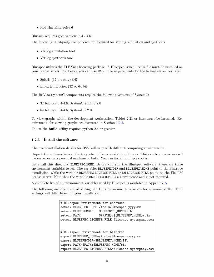
The following are examples of setting the Unix environment variables for common shells. Yoursettings will differ based on your installation.
# Bluespec Environment for csh/tcsh
setenv BLUESPEC_HOME /tools/Bluespec-yyyy.mm
setenv BLUESPECDIR $BLUESPEC_HOME/lib
setenv PATH ${PATH}:${BLUESPEC_HOME}/bin
setenv BLUESPEC_LICENSE_FILE @license.mycompany.com
# Bluespec Environment for bash/ksh
export BLUESPEC_HOME=/tools/Bluespec-yyyy.mm
export BLUESPECDIR=$BLUESPEC_HOME/lib
export PATH=$PATH:$BLUESPEC_HOME/bin
export [email protected]
8
1.2.4 License Files
Bluespec utilizes the FLEXnet licensing package. A Bluespec-issued license file must be installedbefore you can use BSV. To generate the license file, Bluespec requires the FLexLM hostid of yourFlexLM license server. Email the hostid to Bluespec support. Your system administrator may beable to provide this to you directly. If not, you can find it by using the lmhostid command on thelicense server.
All licensing files, including the lmhostid command, are located in the $BLUESPEC HOME/util/flexlm
directory. This directory contains FLEXnet licensing executables and Bluespec specific daemons.The subdirectories are specific to machine architecture and operating system. The README file liststhe daemons currently supported by Bluespec, as well as directions for editing the license file.
Note that the FlexLM hostid is not the same as what is printed by the ordinary hostid command.The FlexLM hostid is typically a string of 12 hex digits for a license server running on Linux/x86 anda string of 8 hex digits for license server running on Solaris/Sun. Although the Bluespec softwareonly runs under Linux, the license server can be networked server running Linux or Sun/Solaris.
Using your FlexLM hostid, Bluespec will generate a FlexLM license file for your license server andemail to you. Install this license file on your FlexLM license server. Your system administratorshould be able to help with this.
Before you run the Bluespec software, set up the environment variable BLUESPEC LICENSE FILE orLM LICENSE FILE to point to your FLexLM license server.
Refer to the FLEXnet user guide, LicensingEndUserGuide.pdf, for more details on managingand running the FLEXnet licensing package. Bluespec flags relating to licensing are discussed inSection 7.8.
1.2.5 Viewing graphs and installing Tcldot
The Tcldot package is used by the Bluespec Development Workstation (BDW) to display schedulinggraphs.
Note, the standalone Bluespec compiler (bsc command) does not depend on Tcldot. When compilingwith the flag -sched-dot the compiler generates scheduling graph files which are named in thefollowing style:
<Module>_<GraphType>.dot
To view the generated scheduling graphs without the BDW, you can use any of a number of 3rd-party packages capable of displaying .dot files. One example is the viewer application called dot.dot converts a .dot file to a pdf or png format.
To view the graphs from the BDW, you must install Tcldot, which is an add-on to the graphvizpackage. Unfortunately, a newer version of Tcldot (2.21 or greater) is required than the one whichcome with the standard linux distributions. Tcldot can be downloaded from www.graphviz.org.
To verify if Tcldot is installed, start a Tcl/wish shell to see if and where Tcldot is available on yoursystem.
• On a linux command line start wish:
linux>wish
An empty wish window will pop-up. On the command line the wish shell will have the tclcommand prompt %.
9
• Load the Tcldot package from the wish shell:
% package require Tcldot
If installed, the version number will be returned. The version must be greater than 2.21. Ifthis step fails (package not found), Tcldot is not installed or not found in your path.
• Verify where in tcl’s search path Tcldot was found:
% puts $auto_path
This will return tcl’s search path. Example:
/usr/share/tcltk/tcl8.5 /usr/lib /usr/local/lib/tcltk
/usr/local/share/tcltk /usr/lib/tcltk /usr/lib/tcltk/graphviz
You should find an obvious entry for graphviz.
To update the tcl search path in the BDW
• Create the file ${HOME}/.bluetclrc
• Add the following line to the bluetclrc file, using the graphviz search path found above:
lappend auto_path /user/lib/tcltk/graphviz/
• Save the file and launch the workstation
1.3 Components of BSV Release
BSV is released with the following components:
• The BSV language syntax: BSV allows a designer to develop a high-level, behavioral, hardwaredesign utilizing atomic rules, which can be compiled to a Verilog RTL design. For a completedescription of the BSV language, refer to the BSV Reference Guide.
• BSV compiler: The compiler takes BSV syntax and generates a hardware description, foreither Verilog or Bluesim.
• BSV library packages: BSV is shipped with a growing set of libraries which provide commonand useful programming idioms and hardware structures.
• Verilog library modules: Several primitive BSV elements, such as FIFOs and registers, areexpressed as Verilog primitives.
• Bluesim: a cycle simulator for BSV designs.
• Bluetcl: a collection of Tcl extensions, scripts, and packages to link into a Bluespec design.
• Bluespec Workstation: An integrated graphical design environment encompassing all Bluespeccomponents as well as third-party design tools, including simulators, waveform viewers andeditors.
Also included is a complete set of documentation, including tutorials, examples and white papers.The $BLUESPEC HOME/doc/BSV directory contains this user guide, the BSV Reference Guide, a BSVby Example guide and a known problems and solutions reference (kpns).
10
• User Guide: This manual which explains how to run the development workstation, the compiler(binary), what flags are available, and how to read the tool output.
• BSV Reference Guide: The BSV Reference Guide is a stand-alone reference that fully describesthe subset of SystemVerilog supported by the Bluespec Compiler.
• BSV by Example: This book teaches the BSV language through small, complete, executableBSV programs. While not an exhaustive reference manual of all BSV features, it describesmany of the most commonly used features.
• KPNS: The known problems and solutions (kpns) describe some known issues with the compilerand their solutions.
All of the documentation, along with tutorials, papers, and examples can be accessed from theHelp→BSV option on the main toolbar of the development workstation. There is also available ahyperlinked documentation index, index.html, installed in the $BLUESPEC HOME directory.
1.4 Utilities
Bluespec provides BSV editing modes for the editors emacs, vim, and jedit. The files are insubdirectories in the $BLUESPEC HOME/util directory. Each directory contains a README file withinstallation instructions for the editor.
The $BLUESPEC HOME/util directory also contains an GNU enscript .st file for printing BluespecSystemVerilog language files. A README file in the directory contains instructions for installationand use.
1.5 Quick Start
Once Bluespec is installed, and the Unix environment variables are set, execute the commandbluespec to start the development workstation:
bluespec
This command brings up main workstation window, from which you can perform all Bluespec tasks.
You can also add the name of an existing Bluespec project file as you start the workstation:
bluespec project.bspec
where project.bspec is the project file name. This starts the workstation and opens the project.The project file contains the saved project preferences and settings.
From the command line, you can invoke the BSV compiler with:
bsc arguments
11
2 Designing with Bluespec
2.1 Components of a BSV Design
A BSV program consists of one or more outermost constructs called packages. All BSV code isassumed to be inside a package. Furthermore, the BSV compiler and other tools assume that thereis one package per file, and they use the package name to derive the file name. For example, apackage called Foo is assumed to be located in the file Foo.bsv.
When using the Bluespec development workstation you will also have a project file, (project-name.bspec), which is a saved collection of options and parameters. Only the development work-station defines project files; you do not have a .bspec project file if you use Bluespec completelyfrom the Unix command line.
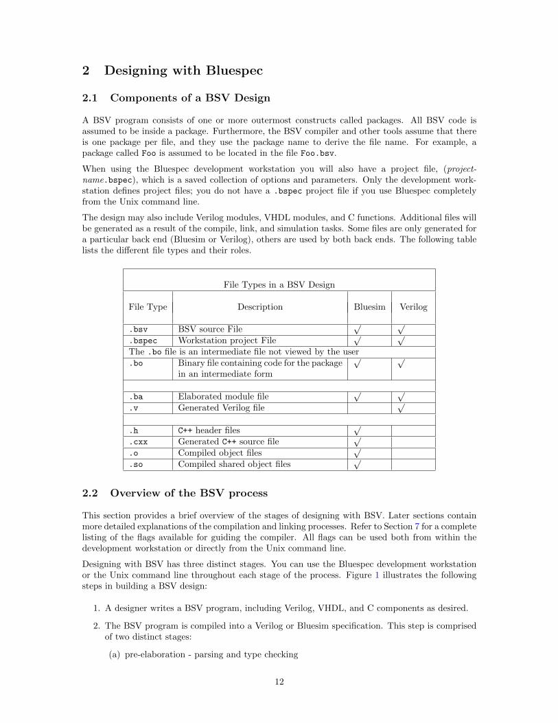
The design may also include Verilog modules, VHDL modules, and C functions. Additional files willbe generated as a result of the compile, link, and simulation tasks. Some files are only generated fora particular back end (Bluesim or Verilog), others are used by both back ends. The following tablelists the different file types and their roles.
File Types in a BSV Design
File Type Description Bluesim Verilog
.bsv BSV source File√ √
.bspec Workstation project File√ √
The .bo file is an intermediate file not viewed by the user.bo Binary file containing code for the package
in an intermediate form
√ √
.ba Elaborated module file√ √
.v Generated Verilog file√
.h C++ header files√
.cxx Generated C++ source file√
.o Compiled object files√
.so Compiled shared object files√
2.2 Overview of the BSV process
This section provides a brief overview of the stages of designing with BSV. Later sections containmore detailed explanations of the compilation and linking processes. Refer to Section 7 for a completelisting of the flags available for guiding the compiler. All flags can be used both from within thedevelopment workstation or directly from the Unix command line.
Designing with BSV has three distinct stages. You can use the Bluespec development workstationor the Unix command line throughout each stage of the process. Figure 1 illustrates the followingsteps in building a BSV design:
1. A designer writes a BSV program, including Verilog, VHDL, and C components as desired.
2. The BSV program is compiled into a Verilog or Bluesim specification. This step is comprisedof two distinct stages:
(a) pre-elaboration - parsing and type checking
12
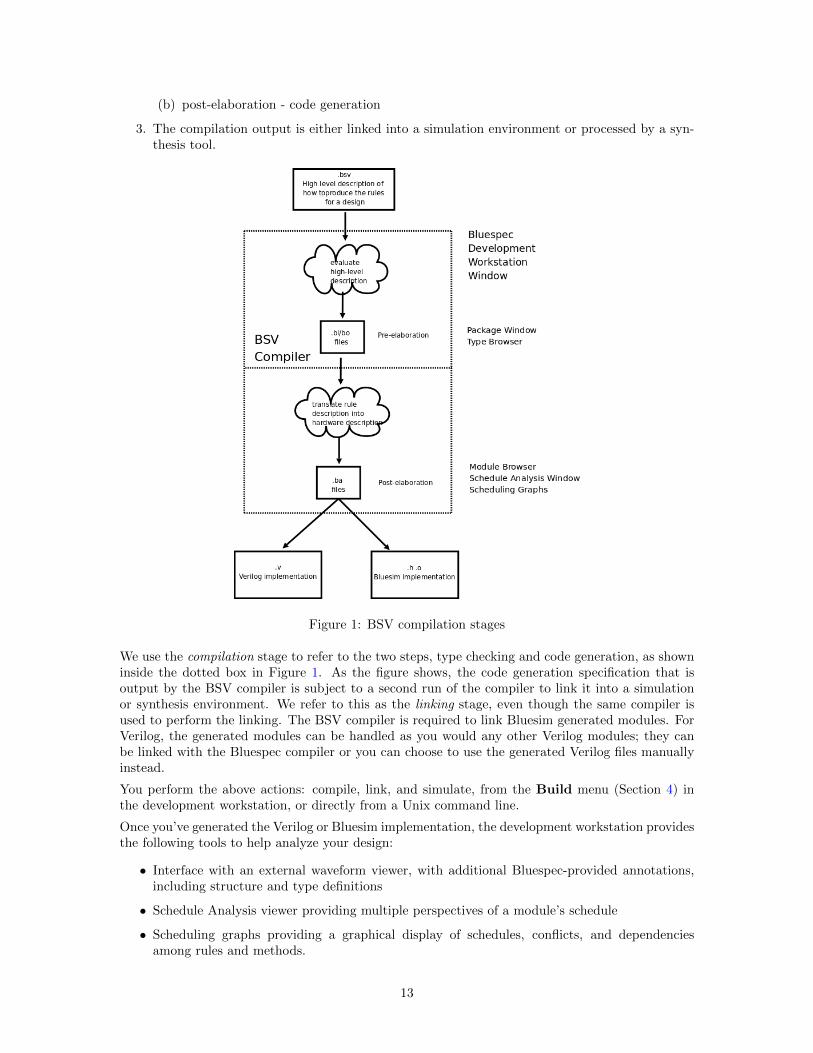
(b) post-elaboration - code generation
3. The compilation output is either linked into a simulation environment or processed by a syn-thesis tool.
Figure 1: BSV compilation stages
We use the compilation stage to refer to the two steps, type checking and code generation, as showninside the dotted box in Figure 1. As the figure shows, the code generation specification that isoutput by the BSV compiler is subject to a second run of the compiler to link it into a simulationor synthesis environment. We refer to this as the linking stage, even though the same compiler isused to perform the linking. The BSV compiler is required to link Bluesim generated modules. ForVerilog, the generated modules can be handled as you would any other Verilog modules; they canbe linked with the Bluespec compiler or you can choose to use the generated Verilog files manuallyinstead.
You perform the above actions: compile, link, and simulate, from the Build menu (Section 4) inthe development workstation, or directly from a Unix command line.
Once you’ve generated the Verilog or Bluesim implementation, the development workstation providesthe following tools to help analyze your design:
• Interface with an external waveform viewer, with additional Bluespec-provided annotations,including structure and type definitions
• Schedule Analysis viewer providing multiple perspectives of a module’s schedule
• Scheduling graphs providing a graphical display of schedules, conflicts, and dependenciesamong rules and methods.
13
2.3 Overview of the Bluespec Workstation
2.3.1 Workstation Windows
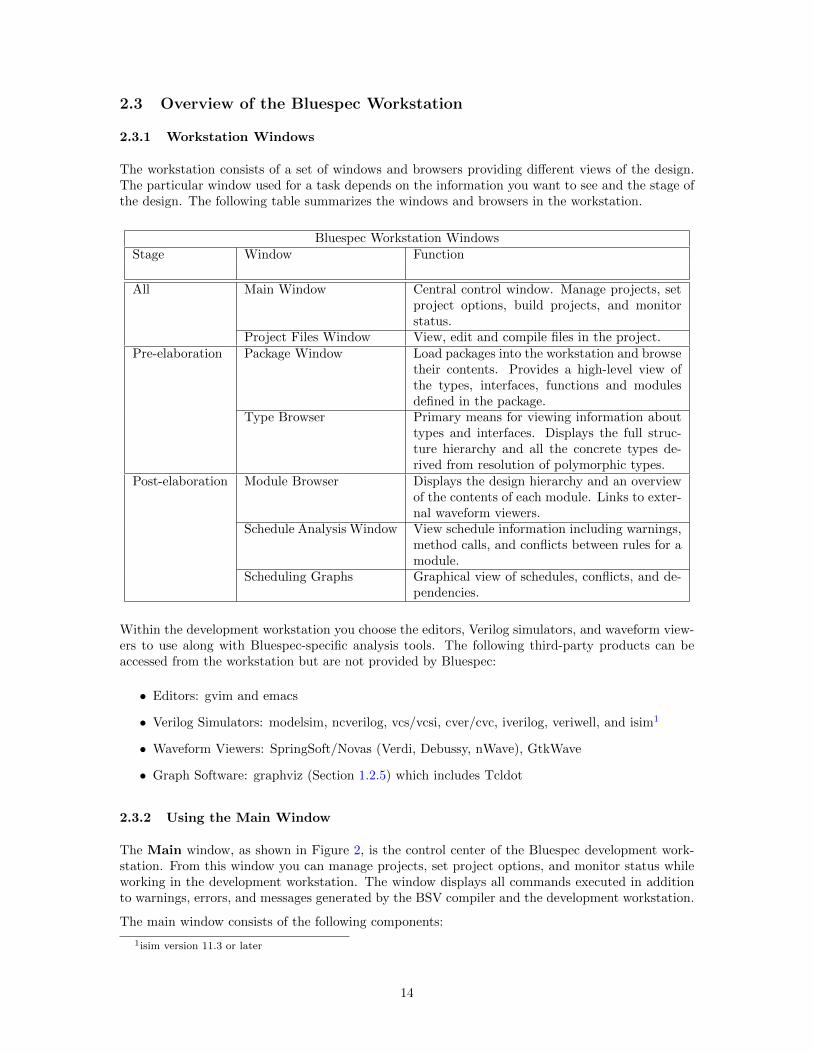
The workstation consists of a set of windows and browsers providing different views of the design.The particular window used for a task depends on the information you want to see and the stage ofthe design. The following table summarizes the windows and browsers in the workstation.
Bluespec Workstation WindowsStage Window Function
All Main Window Central control window. Manage projects, setproject options, build projects, and monitorstatus.
Project Files Window View, edit and compile files in the project.Pre-elaboration Package Window Load packages into the workstation and browse
their contents. Provides a high-level view ofthe types, interfaces, functions and modulesdefined in the package.
Type Browser Primary means for viewing information abouttypes and interfaces. Displays the full struc-ture hierarchy and all the concrete types de-rived from resolution of polymorphic types.
Post-elaboration Module Browser Displays the design hierarchy and an overviewof the contents of each module. Links to exter-nal waveform viewers.
Schedule Analysis Window View schedule information including warnings,method calls, and conflicts between rules for amodule.
Scheduling Graphs Graphical view of schedules, conflicts, and de-pendencies.
Within the development workstation you choose the editors, Verilog simulators, and waveform view-ers to use along with Bluespec-specific analysis tools. The following third-party products can beaccessed from the workstation but are not provided by Bluespec:
• Editors: gvim and emacs
• Verilog Simulators: modelsim, ncverilog, vcs/vcsi, cver/cvc, iverilog, veriwell, and isim1
• Waveform Viewers: SpringSoft/Novas (Verdi, Debussy, nWave), GtkWave
• Graph Software: graphviz (Section 1.2.5) which includes Tcldot
2.3.2 Using the Main Window
The Main window, as shown in Figure 2, is the control center of the Bluespec development work-station. From this window you can manage projects, set project options, and monitor status whileworking in the development workstation. The window displays all commands executed in additionto warnings, errors, and messages generated by the BSV compiler and the development workstation.
The main window consists of the following components:
1isim version 11.3 or later
14
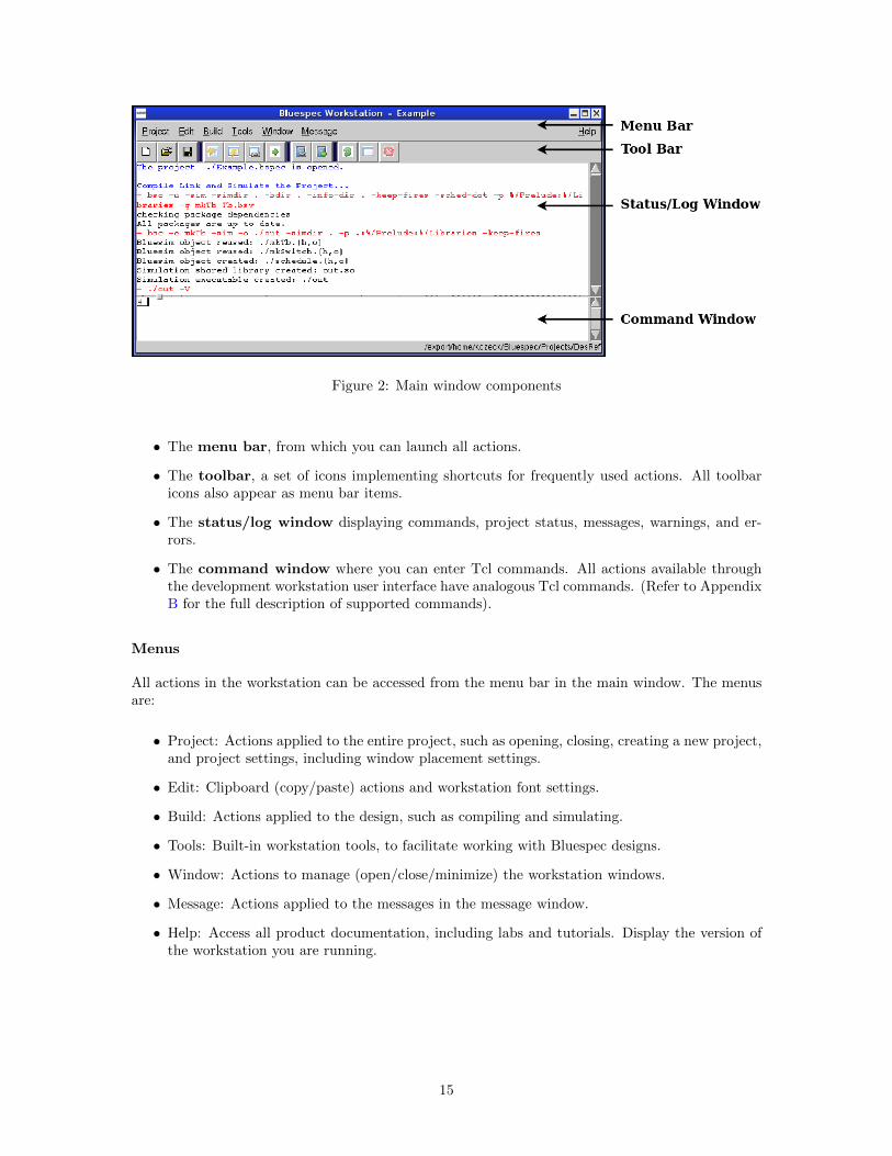
Figure 2: Main window components
• The menu bar, from which you can launch all actions.
• The toolbar, a set of icons implementing shortcuts for frequently used actions. All toolbaricons also appear as menu bar items.
• The status/log window displaying commands, project status, messages, warnings, and er-rors.
• The command window where you can enter Tcl commands. All actions available throughthe development workstation user interface have analogous Tcl commands. (Refer to AppendixB for the full description of supported commands).
Menus
All actions in the workstation can be accessed from the menu bar in the main window. The menusare:
• Project: Actions applied to the entire project, such as opening, closing, creating a new project,and project settings, including window placement settings.
• Edit: Clipboard (copy/paste) actions and workstation font settings.
• Build: Actions applied to the design, such as compiling and simulating.
• Tools: Built-in workstation tools, to facilitate working with Bluespec designs.
• Window: Actions to manage (open/close/minimize) the workstation windows.
• Message: Actions applied to the messages in the message window.
• Help: Access all product documentation, including labs and tutorials. Display the version ofthe workstation you are running.
15
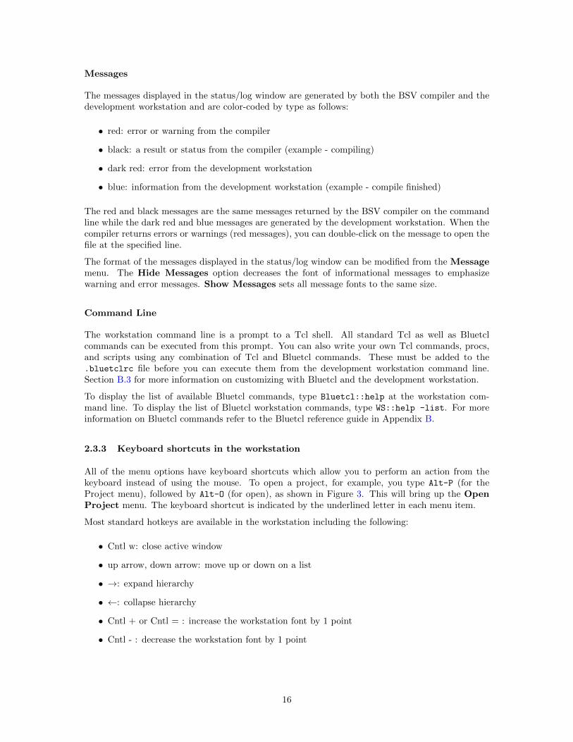
Messages
The messages displayed in the status/log window are generated by both the BSV compiler and thedevelopment workstation and are color-coded by type as follows:
• red: error or warning from the compiler
• black: a result or status from the compiler (example - compiling)
• dark red: error from the development workstation
• blue: information from the development workstation (example - compile finished)
The red and black messages are the same messages returned by the BSV compiler on the commandline while the dark red and blue messages are generated by the development workstation. When thecompiler returns errors or warnings (red messages), you can double-click on the message to open thefile at the specified line.
The format of the messages displayed in the status/log window can be modified from the Messagemenu. The Hide Messages option decreases the font of informational messages to emphasizewarning and error messages. Show Messages sets all message fonts to the same size.
Command Line
The workstation command line is a prompt to a Tcl shell. All standard Tcl as well as Bluetclcommands can be executed from this prompt. You can also write your own Tcl commands, procs,and scripts using any combination of Tcl and Bluetcl commands. These must be added to the.bluetclrc file before you can execute them from the development workstation command line.Section B.3 for more information on customizing with Bluetcl and the development workstation.
To display the list of available Bluetcl commands, type Bluetcl::help at the workstation com-mand line. To display the list of Bluetcl workstation commands, type WS::help -list. For moreinformation on Bluetcl commands refer to the Bluetcl reference guide in Appendix B.
2.3.3 Keyboard shortcuts in the workstation
All of the menu options have keyboard shortcuts which allow you to perform an action from thekeyboard instead of using the mouse. To open a project, for example, you type Alt-P (for theProject menu), followed by Alt-O (for open), as shown in Figure 3. This will bring up the OpenProject menu. The keyboard shortcut is indicated by the underlined letter in each menu item.
Most standard hotkeys are available in the workstation including the following:
• Cntl w: close active window
• up arrow, down arrow: move up or down on a list
• →: expand hierarchy
• ←: collapse hierarchy
• Cntl + or Cntl = : increase the workstation font by 1 point
• Cntl - : decrease the workstation font by 1 point
16
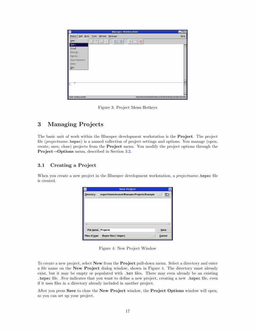
Figure 3: Project Menu Hotkeys
3 Managing Projects
The basic unit of work within the Bluespec development workstation is the Project. The projectfile (projectname.bspec) is a named collection of project settings and options. You manage (open,create, save, close) projects from the Project menu. You modify the project options through theProject→Options menu, described in Section 3.2.
3.1 Creating a Project
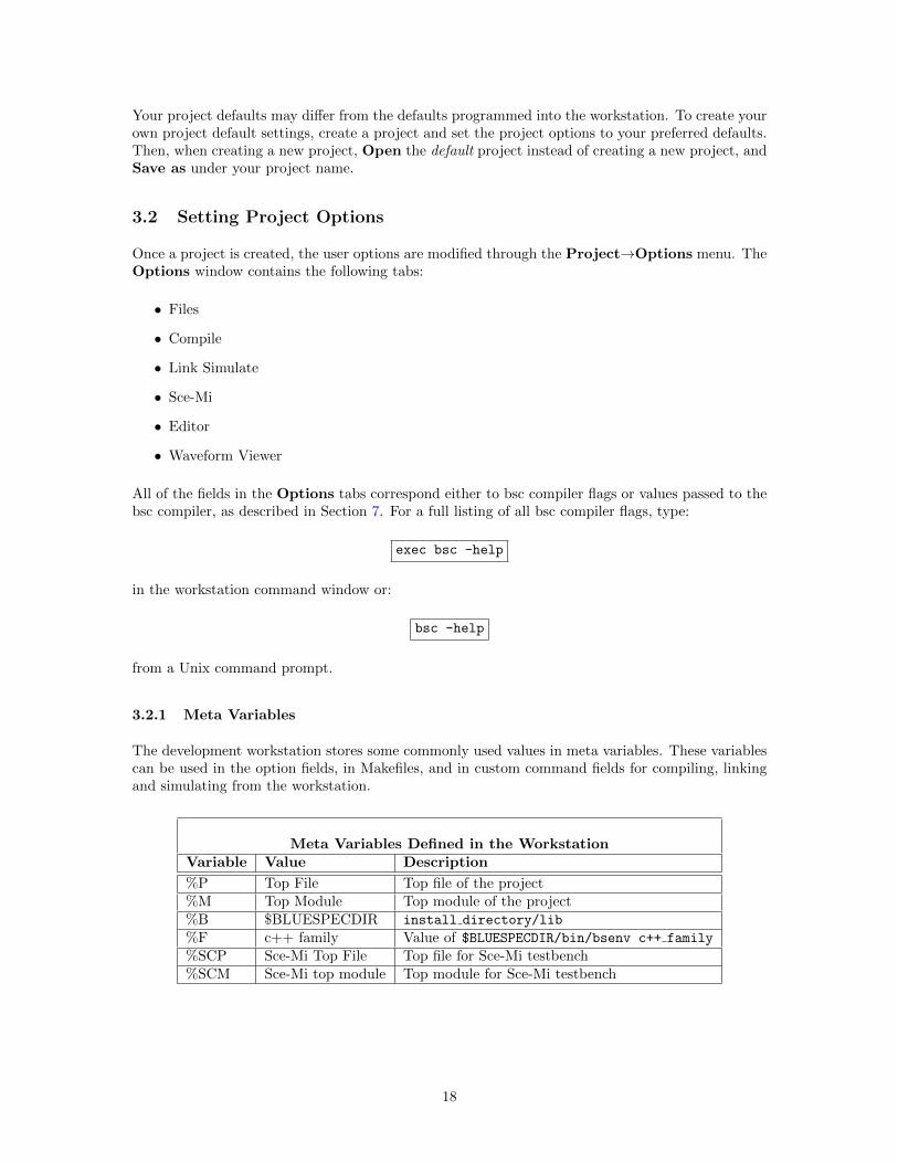
When you create a new project in the Bluespec development workstation, a projectname.bspec fileis created.
Figure 4: New Project Window
To create a new project, select New from the Project pull-down menu. Select a directory and entera file name on the New Project dialog window, shown in Figure 4. The directory must alreadyexist, but it may be empty or populated with .bsv files. There may even already be an existing.bspec file. New indicates that you want to define a new project, creating a new .bspec file, evenif it uses files in a directory already included in another project.
After you press Save to close the New Project window, the Project Options window will open,so you can set up your project.
17
Your project defaults may differ from the defaults programmed into the workstation. To create yourown project default settings, create a project and set the project options to your preferred defaults.Then, when creating a new project, Open the default project instead of creating a new project, andSave as under your project name.
3.2 Setting Project Options
Once a project is created, the user options are modified through the Project→Options menu. TheOptions window contains the following tabs:
• Files
• Compile
• Link Simulate
• Sce-Mi
• Editor
• Waveform Viewer
All of the fields in the Options tabs correspond either to bsc compiler flags or values passed to thebsc compiler, as described in Section 7. For a full listing of all bsc compiler flags, type:
exec bsc -help
in the workstation command window or:
bsc -help
from a Unix command prompt.
3.2.1 Meta Variables
The development workstation stores some commonly used values in meta variables. These variablescan be used in the option fields, in Makefiles, and in custom command fields for compiling, linkingand simulating from the workstation.
Meta Variables Defined in the WorkstationVariable Value Description
%P Top File Top file of the project%M Top Module Top module of the project%B $BLUESPECDIR install directory/lib
%F c++ family Value of $BLUESPECDIR/bin/bsenv c++ family
%SCP Sce-Mi Top File Top file for Sce-Mi testbench%SCM Sce-Mi top module Top module for Sce-Mi testbench
18
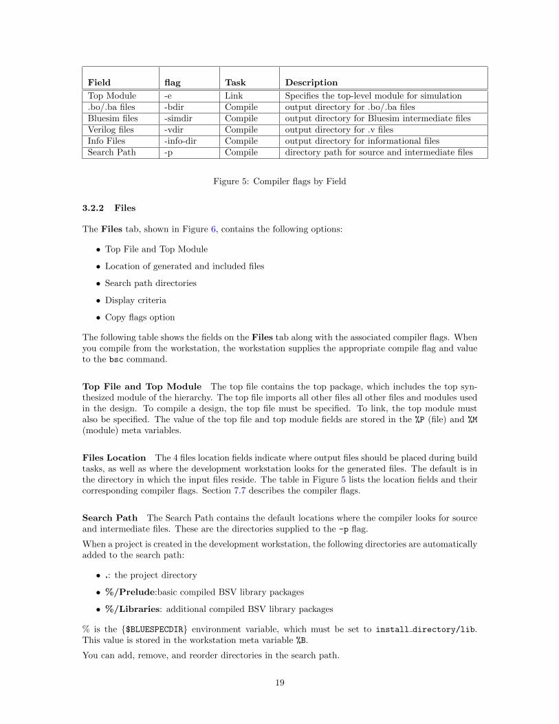
Field flag Task Description
Top Module -e Link Specifies the top-level module for simulation.bo/.ba files -bdir Compile output directory for .bo/.ba filesBluesim files -simdir Compile output directory for Bluesim intermediate filesVerilog files -vdir Compile output directory for .v filesInfo Files -info-dir Compile output directory for informational filesSearch Path -p Compile directory path for source and intermediate files
Figure 5: Compiler flags by Field
3.2.2 Files
The Files tab, shown in Figure 6, contains the following options:
• Top File and Top Module
• Location of generated and included files
• Search path directories
• Display criteria
• Copy flags option
The following table shows the fields on the Files tab along with the associated compiler flags. Whenyou compile from the workstation, the workstation supplies the appropriate compile flag and valueto the bsc command.
Top File and Top Module The top file contains the top package, which includes the top syn-thesized module of the hierarchy. The top file imports all other files all other files and modules usedin the design. To compile a design, the top file must be specified. To link, the top module mustalso be specified. The value of the top file and top module fields are stored in the %P (file) and %M
(module) meta variables.
Files Location The 4 files location fields indicate where output files should be placed during buildtasks, as well as where the development workstation looks for the generated files. The default is inthe directory in which the input files reside. The table in Figure 5 lists the location fields and theircorresponding compiler flags. Section 7.7 describes the compiler flags.
Search Path The Search Path contains the default locations where the compiler looks for sourceand intermediate files. These are the directories supplied to the -p flag.
When a project is created in the development workstation, the following directories are automaticallyadded to the search path:
• .: the project directory
• %/Prelude:basic compiled BSV library packages
• %/Libraries: additional compiled BSV library packages
% is the {$BLUESPECDIR} environment variable, which must be set to install directory/lib.This value is stored in the workstation meta variable %B.
You can add, remove, and reorder directories in the search path.
19
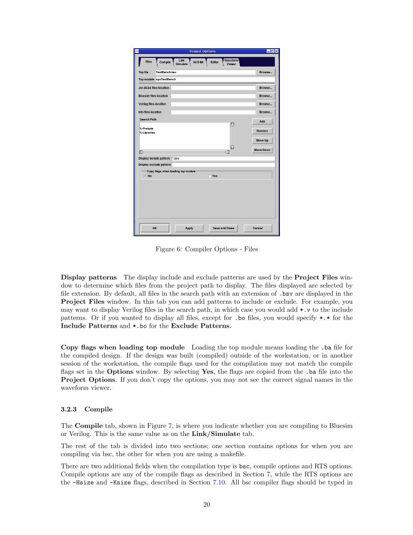
Figure 6: Compiler Options - Files
Display patterns The display include and exclude patterns are used by the Project Files win-dow to determine which files from the project path to display. The files displayed are selected byfile extension. By default, all files in the search path with an extension of .bsv are displayed in theProject Files window. In this tab you can add patterns to include or exclude. For example, youmay want to display Verilog files in the search path, in which case you would add *.v to the includepatterns. Or if you wanted to display all files, except for .bo files, you would specify *.* for theInclude Patterns and *.bo for the Exclude Patterns.
Copy flags when loading top module Loading the top module means loading the .ba file forthe compiled design. If the design was built (compiled) outside of the workstation, or in anothersession of the workstation, the compile flags used for the compilation may not match the compileflags set in the Options window. By selecting Yes, the flags are copied from the .ba file into theProject Options. If you don’t copy the options, you may not see the correct signal names in thewaveform viewer.
3.2.3 Compile
The Compile tab, shown in Figure 7, is where you indicate whether you are compiling to Bluesimor Verilog. This is the same value as on the Link/Simulate tab.
The rest of the tab is divided into two sections; one section contains options for when you arecompiling via bsc, the other for when you are using a makefile.
There are two additional fields when the compilation type is bsc, compile options and RTS options.Compile options are any of the compile flags as described in Section 7, while the RTS options arethe -Hsize and -Ksize flags, described in Section 7.10. All bsc compiler flags should be typed in
20
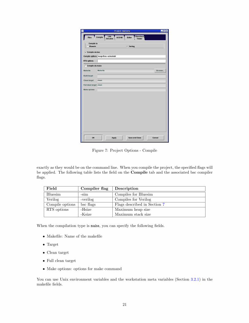
Figure 7: Project Options - Compile
exactly as they would be on the command line. When you compile the project, the specified flags willbe applied. The following table lists the field on the Compile tab and the associated bsc compilerflags.
Field Compiler flag Description
Bluesim -sim Compiles for BluesimVerilog -verilog Compiles for VerilogCompile options bsc flags Flags described in Section 7RTS options -Hsize Maximum heap size
-Ksize Maximum stack size
When the compilation type is make, you can specify the following fields.
• Makefile: Name of the makefile
• Target
• Clean target
• Full clean target
• Make options: options for make command
You can use Unix environment variables and the workstation meta variables (Section 3.2.1) in themakefile fields.
21
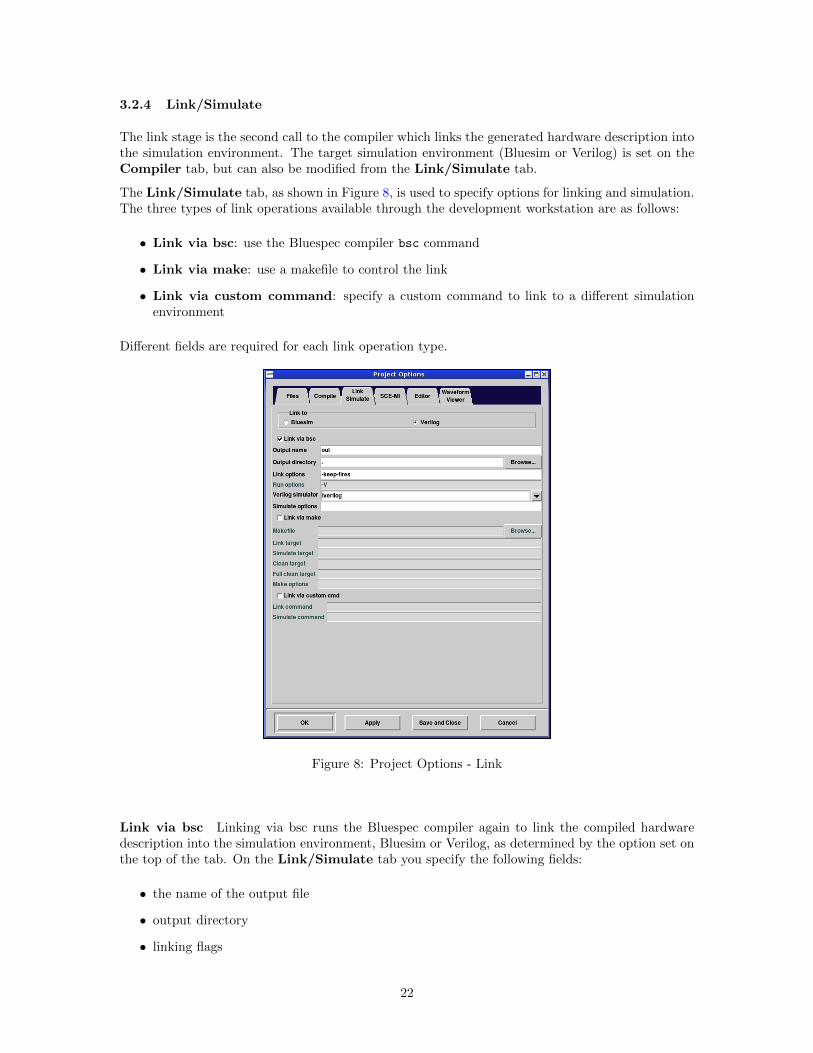
3.2.4 Link/Simulate
The link stage is the second call to the compiler which links the generated hardware description intothe simulation environment. The target simulation environment (Bluesim or Verilog) is set on theCompiler tab, but can also be modified from the Link/Simulate tab.
The Link/Simulate tab, as shown in Figure 8, is used to specify options for linking and simulation.The three types of link operations available through the development workstation are as follows:
• Link via bsc: use the Bluespec compiler bsc command
• Link via make: use a makefile to control the link
• Link via custom command: specify a custom command to link to a different simulationenvironment
Different fields are required for each link operation type.
Figure 8: Project Options - Link
Link via bsc Linking via bsc runs the Bluespec compiler again to link the compiled hardwaredescription into the simulation environment, Bluesim or Verilog, as determined by the option set onthe top of the tab. On the Link/Simulate tab you specify the following fields:
• the name of the output file
• output directory
• linking flags
22
When left blank, the output directory defaults to the current working directory. The output filename and output directory are passed to the bsc command with the -o flag. The following tablelists the field on the Link/Simulate tab and the associated bsc compiler flags.
Field Compiler flag Description
Bluesim -sim Compiles for BluesimVerilog -verilog Compiles for VerilogOutput name -o Name for the binary being created; the default
name is a.out
Link options bsc flags Flags described in Section 7Simulator -vsim Specifies which Verilog simulator to use
Simulate If compiling to Bluesim, you can specify Bluesim run options, such as the -V flag togenerate VCD files, in the Simulate options field.
If the Compile to target is Verilog, the following simulators can be chosen in the Link/Simulatetab:
• iverilog
• modelsim
• ncverilog
• vcs/vcsi
• cver/cvc
• veriwell
• isim
When using any of the above simulators, use the Simulate options field to specify the simulationplusarg variables +bscvcd and +bsccycle, as described in Section 4.3.3.
Link via make The fields on the Link/Simulate tab for Link via make are as follows:
• Makefile
• Target
• Simulation Target
• Clean Target
• Options
You can use Unix environment variables and the workstation meta variables (Section 3.2.1) in themakefile fields.
Linking via custom command You can use other simulation environments, by supplying theLink command and the command to launch the simulator (Simulate Command). This allows you tolink the design with any simulation environment you choose.
You can use Unix environment variables and the workstation meta variables (Section 3.2.1) in thelink and simulate command fields.
23
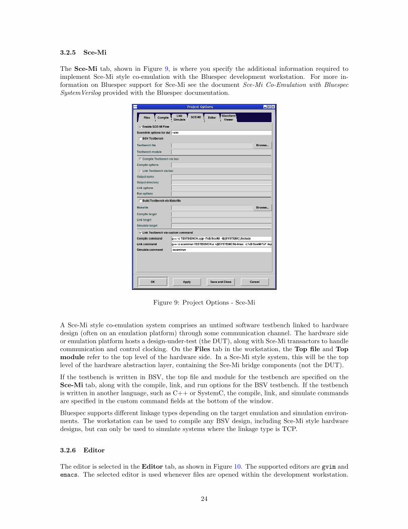
3.2.5 Sce-Mi
The Sce-Mi tab, shown in Figure 9, is where you specify the additional information required toimplement Sce-Mi style co-emulation with the Bluespec development workstation. For more in-formation on Bluespec support for Sce-Mi see the document Sce-Mi Co-Emulation with BluespecSystemVerilog provided with the Bluespec documentation.
Figure 9: Project Options - Sce-Mi
A Sce-Mi style co-emulation system comprises an untimed software testbench linked to hardwaredesign (often on an emulation platform) through some communication channel. The hardware sideor emulation platform hosts a design-under-test (the DUT), along with Sce-Mi transactors to handlecommunication and control clocking. On the Files tab in the workstation, the Top file and Topmodule refer to the top level of the hardware side. In a Sce-Mi style system, this will be the toplevel of the hardware abstraction layer, containing the Sce-Mi bridge components (not the DUT).
If the testbench is written in BSV, the top file and module for the testbench are specified on theSce-Mi tab, along with the compile, link, and run options for the BSV testbench. If the testbenchis written in another language, such as C++ or SystemC, the compile, link, and simulate commandsare specified in the custom command fields at the bottom of the window.
Bluespec supports different linkage types depending on the target emulation and simulation environ-ments. The workstation can be used to compile any BSV design, including Sce-Mi style hardwaredesigns, but can only be used to simulate systems where the linkage type is TCP.
3.2.6 Editor
The editor is selected in the Editor tab, as shown in Figure 10. The supported editors are gvim andemacs. The selected editor is used whenever files are opened within the development workstation.
24
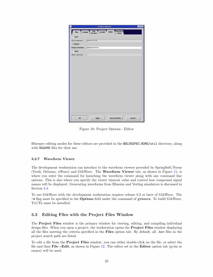
Figure 10: Project Options - Editor
Bluespec editing modes for these editors are provided in the $BLUESPEC HOME/util directory, alongwith README files for their use.
3.2.7 Waveform Viewer
The development workstation can interface to the waveform viewers provided by SpringSoft/Novas(Verdi, Debussy, nWave) and GtkWave. The Waveform Viewer tab, as shown in Figure 11, iswhere you enter the command for launching the waveform viewer along with any command lineoptions. This is also where you specify the viewer timeout value and control how compound signalnames will be displayed. Generating waveforms from Bluesim and Verilog simulators is discussed inSection 4.4.
To use GtkWave with the development workstation requires release 3.3 or later of GtkWave. The-W flag must be specified in the Options field under the command of gtkwave. To build GtkWave,Tcl/Tk must be installed.
3.3 Editing Files with the Project Files Window
The Project Files window is the primary window for viewing, editing, and compiling individualdesign files. When you open a project, the workstation opens the Project Files window displayingall the files meeting the criteria specified in the Files option tab. By default, all .bsv files in theproject search path are listed.
To edit a file from the Project Files window, you can either double-click on the file, or select thefile and then File→Edit, as shown in Figure 12. The editor set in the Editor option tab (gvim oremacs) will be used.
25
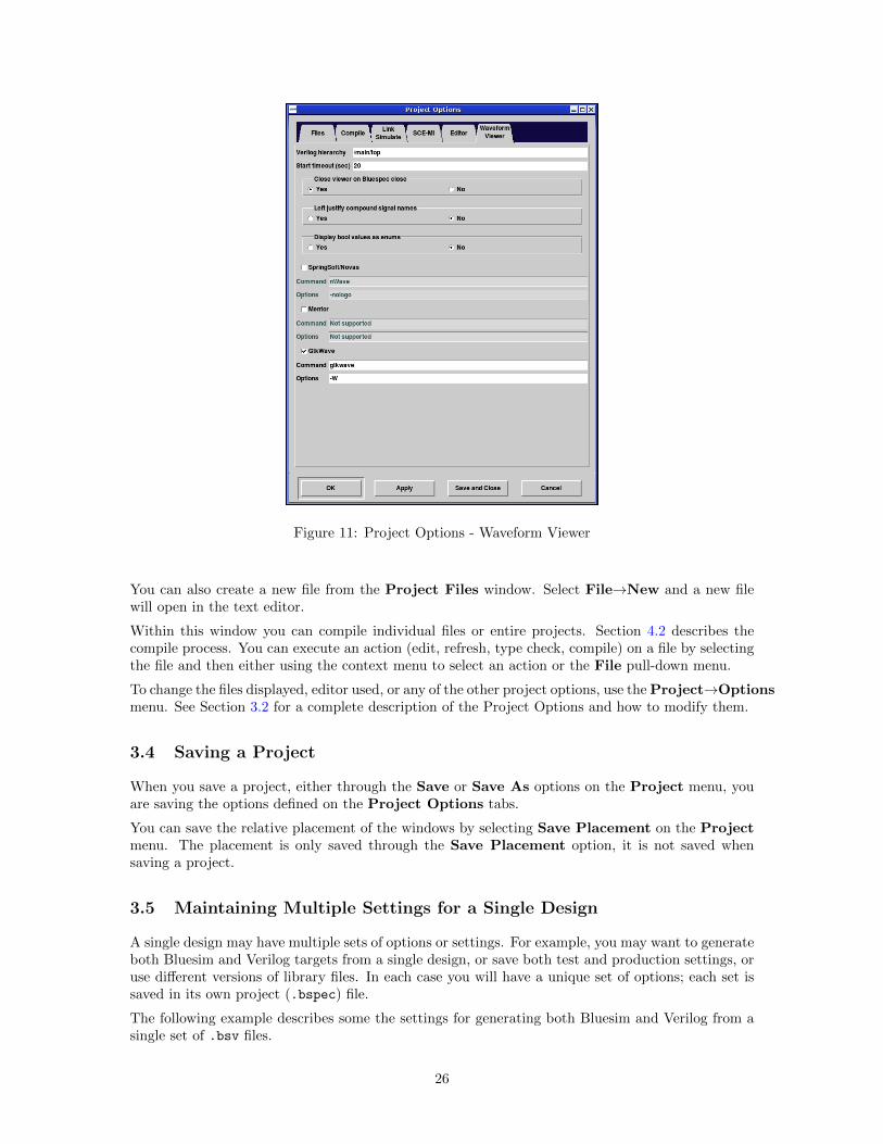
Figure 11: Project Options - Waveform Viewer
You can also create a new file from the Project Files window. Select File→New and a new filewill open in the text editor.
Within this window you can compile individual files or entire projects. Section 4.2 describes thecompile process. You can execute an action (edit, refresh, type check, compile) on a file by selectingthe file and then either using the context menu to select an action or the File pull-down menu.
To change the files displayed, editor used, or any of the other project options, use the Project→Optionsmenu. See Section 3.2 for a complete description of the Project Options and how to modify them.
3.4 Saving a Project
When you save a project, either through the Save or Save As options on the Project menu, youare saving the options defined on the Project Options tabs.
You can save the relative placement of the windows by selecting Save Placement on the Projectmenu. The placement is only saved through the Save Placement option, it is not saved whensaving a project.
3.5 Maintaining Multiple Settings for a Single Design
A single design may have multiple sets of options or settings. For example, you may want to generateboth Bluesim and Verilog targets from a single design, or save both test and production settings, oruse different versions of library files. In each case you will have a unique set of options; each set issaved in its own project (.bspec) file.
The following example describes some the settings for generating both Bluesim and Verilog from asingle set of .bsv files.
26

Figure 12: Project Files Window
• Each target is its own project, defined by its own .bspec file.
• The same .bsv files are used in both projects therefore the project directories are the same.
• In the Project Options the following fields are different:
– In the Files tab different output directories are specified for each project so the generatedfiles are not overwritten when the other target is compiled. All output files (Bluesim orVerilog, .bo/.ba, Info files) have different directories specified for each project.
– In the Compile tab, the target is set to Bluesim in one project, and Verilog in the other.
– Also in the Compile tab different compiler flags may be used for each target.
• In the Link/Simulate tab, different output directories are specified and well as link compileroptions for each project.
• Also in the Link/Simulate tab different simulators are specified along with any options forthe simulator.
The development workstation project saves each group of settings and options in the .bspec file,allowing you to maintain multiple design environments for single set of .bsv files.
4 Building a Project
Building a project includes running the compiler and simulating designs. All build options areavailable from the Build menu and on the toolbar, as shown in Figure 13. Additional build optionsinclude stopping active processes and removing generated files (Clean and Full Clean). Someoptions combine multiple build actions into single option or button, for example, Compile + Link.
4.1 Type Check
There are two stages in compilation, type checking and code generation, executed by a single compilecommand. The simplest compilation of a BSV design is to run only the first stage of the compilerwhich is the Type Check task, generating the .bo files. Once the type check is complete, you haveenough module information to use the Package and the Type Browser windows. When you select
27
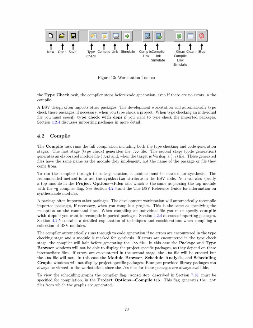
Figure 13: Workstation Toolbar
the Type Check task, the compiler stops before code generation, even if there are no errors in thecompile.
A BSV design often imports other packages. The development workstation will automatically typecheck those packages, if necessary, when you type check a project. When type checking an individualfile you must specify type check with deps if you want to type check the imported packages.Section 4.2.4 discusses importing packages in more detail.
4.2 Compile
The Compile task runs the full compilation including both the type checking and code generationstages. The first stage (type check) generates the .bo file. The second stage (code generation)generates an elaborated module file (.ba) and, when the target is Verilog, a (.v) file. These generatedfiles have the same name as the module they implement, not the name of the package or file theycome from.
To run the compiler through to code generation, a module must be marked for synthesis. Therecommended method is to use the synthesize attribute in the BSV code. You can also specifya top module in the Project Options→Files tab, which is the same as passing the top modulewith the -g compiler flag. See Section 4.2.3 and the The BSV Reference Guide for information onsynthesizable modules.
A package often imports other packages. The development workstation will automatically recompileimported packages, if necessary, when you compile a project. This is the same as specifying the-u option on the command line. When compiling an individual file you must specify compilewith deps if you want to recompile imported packages. Section 4.2.4 discusses importing packages.Section 4.2.5 contains a detailed explanation of techniques and considerations when compiling acollection of BSV modules.
The compiler automatically runs through to code generation if no errors are encountered in the typechecking stage and a module is marked for synthesis. If errors are encountered in the type checkstage, the compiler will halt before generating the .bo file. In this case the Package and TypeBrowser windows will not be able to display the project specific packages, as they depend on theseintermediate files. If errors are encountered in the second stage, the .bo file will be created butthe .ba file will not. In this case the Module Browser, Schedule Analysis, and SchedulingGraphs windows will not display project-specific packages. Bluespec-provided library packages canalways be viewed in the workstation, since the .bo files for these packages are always available.
To view the scheduling graphs the compiler flag -sched-dot, described in Section 7.15, must bespecified for compilation, in the Project Options→Compile tab. This flag generates the .dot
files from which the graphs are generated.
28
4.2.1 Compiling a File
A project usually contains multiple packages and files. To compile a single file, use the ProjectFiles window. Select the file to be compiled and then Compile, from either the File pull-downmenu or the context menu.
A BSV source file is compiled from the command line with a command like this:
bsc [flags] Foo.bsv
where one or more compiler flags may be specified after the bsc command. Section 7.1 describescompiling from the command line in more detail.
Compiling with dependencies Compiling with dependencies means that you want to compileany imported files, if necessary, before compiling the selected file. This is equivalent to compilingwith the -u flag. The compiler compares the time stamp on the .bo file to determine if the importedfile has changed since the last compilation. When you compile with dependencies only changedfiles will be recompiled. You can choose Compile with Deps from both the File and the contextmenus.
4.2.2 Compiling a Project
You can compile your complete project from the toolbar, the Build menu or the Project Fileswindow. Before compiling, the file to be compiled must be specified in the top file field on theFiles option tab.
The top module is not required for compiling, but is required for linking. If the top module isnot specified, the synthesize attribute must be used in the BSV code to compile through codegeneration. Otherwise, the project will only be compiled through elaboration, generating the .bo
file, but not the .ba file. Specifying the top module in the Files tab is equivalent to using the -g
flag with the name of the module.
When compiling a project from the development workstation the -u flag is always used; timestampson all imported files are checked and files are recompiled as necessary.
4.2.3 Specifying modules for code generation
A module can be selected for code generation either in the BSV code or at compile-time. The recom-mended method is to mark the module for code generation in the BSV code, using the synthesize
attribute (see the BSV Reference Guide for more information on attributes). The alternative is atcompile-time, to use the Top Module field which instructs the compiler to generate code for aparticular module. This is the same as using the -g flag (Section 7.1) on the Unix command linewith the bsc command, From the command line, the -g flag can be used multiple times within acompile command line to specify multiple modules for code generation.
Whether the generated code will be Bluesim or Verilog depends on which back end has been selected,either through the Options window or by using the -verilog or -sim command line flag.
Not all modules written in BSV are synthesizable. To be synthesized the module must be of typeModule and not of any other module type that can be defined with ModuleCollect. A module issynthesizable if its interface is a type whose methods and subinterfaces are all convertible to wires.
A method is convertible to wires if it meets the following conditions:
• its argument types are convertible to wires which means either
29
– it is in the Bits class OR
– it is a function whose argument and return type are convertible to wires
• its return type is Action OR
• its return type is a value or ActionValue where either
– the value is convertible to bits (i.e. in the Bits class) OR
– the field is an exported clock or reset.
A module to be synthesized is allowed to have non-interface inputs, such as clocks and resets.Parameters to the module are allowed if they are convertible to bits.
Clock and Reset subinterfaces are convertible to wires.
If none of the modules are marked for synthesis, the compiler will not generate a hardware description(a Verilog .v file or a Bluesim .ba file).
4.2.4 Importing other packages
To compile a package that imports another package, the BSV compiler needs the .bo file from theimported package. One way to provide this file is to run the compiler on each imported file. Orthe development workstation will automatically determine which files are needed and recompile asnecessary, when compiling a project. If the .bo file already exists, the compiler will only recompileif the file has changed since the last compilation, as indicated by the imported file having a morerecent date than the file being compiled.
For example, to compile a package Foo that imports another package Baz, the BSV compiler needsto examine the file Baz.bo. If Baz is in the file Baz.bsv, then this file needs to be run through thecompiler to produce the necessary .bo file before the compiler can be invoked on Foo.bsv. If in theworkstation you compile a project or compile a file with dependencies, or if you use the -u flag onthe command line, the compiler will check to see if Baz.bo exists, and if it exists, it will check thecompilation date. The compiler will recompile the Baz file if necessary.
BSV is shipped with a large set of library files providing common and useful hardware structures,such as FIFO and UInt. They are described in the BSV Reference Guide. The source code for thesepackages is already compiled and the .bo files are found in a library directory with the compilerinstallation (in the same way that C header and object files are stored in standard include andlibrary directories). The compiler looks for these files in:
%/Prelude/
%/Libraries/
The Bluespec Prelude and Libraries directories are automatically added to the search path whena project is created in the workstation.
If you are importing packages from other directories, the directories must be added to the searchpath. In the workstation use the Files tab on the Options menu, as described in Section 3.2.2, tomodify the path. The flags which modify the path from the command line are described in Section7.7.
BSV is also shipped with a set of library files for which both the BSV source is provided in theBSVSource directory, along with compiled .bo files in the Libraries directory. You can use thesepackages as provided, or edit and customize them to your own specifications. To use a customizedversion of the these files, include the directory containing the .bsv source files in the search path. Ifthe directory containing the .bsv files is in any position in the search path, the modified .bsv willbe used, and not the precompiled .bo files from the Libraries directory.
30
4.2.5 Understanding separate compilation
The BSV compiler has two main stages; first it converts BSV modules into a collection of states andrules, and then it converts the rule-representation into a hardware description.
When compiling a collection of BSV modules, it is up to the user to decide which of these modulesshould be compiled to hardware separately, and which should be subsumed into the parent module.By default, all hierarchy is flattened into one top-level module in the final hardware description,but the user can specify modules which should stay in the hierarchy and have separate hardwaredescriptions.
What happens when a module m1 instantiates another module m2? If the submodule m2 is providedas a BSV description, that description will need to be compiled into a set of rules and then thoserules combined with the rules for m1 to be converted, by the code generation stage, into a hardwaredescription.
If m2 is provided as a hardware description (that is, implemented in a Verilog file or in Bluesimheader and object files), then the hardware description for m1 will contain an instantiation of m2.The implementation of m2 is kept in its own file. For the Verilog back end, this produces a m1.v
file with a Verilog module m1 which instantiates m2 by name and connects to its ports but doesn’tcontain the implementation of m2. Both implementation files, m1.v and m2.v, must be provided tothe simulation or synthesis tools.
Even if m2 is provided as a BSV description, the user can decide to generate a separate hardwaredescription for the module. This is done by putting the synthesize attribute in the BSV descriptionor using the -g flag, indicating that the module should be synthesized as a separate module, apartfrom the instantiating module.
The implementation in a .bo reflects whether hardware was generated for a module. If a hardwaredescription was generated for a module, then the implementation in the .bo will be merely a pointerto the location of that description (be it .v or .o). If hardware was not generated for the module,then an entirely BSV representation will be stored in the .bo file.
Thus, a single .bsv file can be compiled in different ways to produce very different .bo files. Whenthe compiler is generating hardware for another BSV file that imports this package, it will need toread in the information in the .bo file. How it is compiled depends on the flags used. Therefore,compiling the new file will be affected by how the imported file was compiled earlier! It is important,therefore, to remove these automatically generated files before beginning a new compilation project,especially if a different module hierarchy is desired.
For example, if a user were to generate Verilog for a module mkFoo just for testing purposes, theFoo.bo would encapsulate into its own description the information that a Verilog module had beengenerated for module mkFoo. If the user then wanted to generate Verilog for a larger design, whichincluded this module, but wanted the larger design to be compiled into one, hierarchy-free Verilogmodule, then the .bo file would have to be deleted so that a new version could be created that onlycontained the state-and-rules description of the module.
When using the development workstation the Clean tasks (Section 4.6) will remove these files. TheClean task removes the .bo files, while the Real Clean task removes the generated Verilog (.v)files as well.
4.2.6 Interfacing to foreign modules and functions
Foreign modules and functions can be included as part of a BSV model. A designer can specifythat the implementation of a particular BSV module is provided as either a Verilog module or a Cfunction.
31
Importing Verilog modules
Using the import "BVI" syntax, a designer can specify that the implementation of a particularBSV module is an RTL (Verilog or VHDL) module, as described in the BSV Reference Guide. Themodule is treated exactly as if it were originally written in BSV and then converted to hardware bythe compiler, but instead of the .v file being generated by the compiler, it was supplied independentlyof any BSV code. It may have been written by hand or supplied by a vendor as an IP, etc. The filesfor these modules need to be linked in to the simulation. This process is described in Section 4.3.1for Bluesim simulations and 4.3.3 for Verilog simulations.
Several primitive BSV elements, such as FIFOs and register files, are expressed this way — as Verilogprimitives. When simulating or synthesizing a design generated with the Verilog back end, you willneed to include the appropriate hardware descriptions for these primitives. Verilog descriptions forBluespec-provided primitive elements can be found in:
${BLUESPECDIR}/Verilog/
Note: We attempt to be sure that the Bluesim and Verilog models simulate identically. Simulationsusing 4-state (X and Z) logic, user supplied Verilog, or other unsupported or nonstandard parts arenever guaranteed to match.
Importing C functions
Using the importBDPI syntax, the user can specify that the implementation of a BSV function isprovided as a C function. The same implementation can be used when simulating with Bluesimor with Verilog. In Bluesim, the imported functions are called directly. In Verilog, the functionsare accessed via the Verilog VPI. The compilation and linking procedures for these backends aredescribed in Sections 4.3.1 for Bluesim simulations, and 4.3.3 for Verilog simulations.
4.3 Link
The compiled hardware description must be linked into a simulation environment before you cansimulate the project. The result of the linking stage is a binary which, when executed, simulates amodule. The Bluespec compiler is required for linking Bluesim generated modules and can be usedto link Verilog modules as well. To link in the workstation, select Link from the toolbar or theBuild menu. To link from the command line, use the bsc command along with the appropriateflags, as described in Section 7.1.
The simulation environment and location of the implementation files are specified in the Filestab of the Options menu. The top-level module must also be specified in Files tab of the theOptions menu. You can specify additional link compiler flags, as described in Section 7, in theLink/Simulate tab of the Options menu.
If you’ve compiled your design and you still cannot link (the Link option is grayed out), the designis not ready to be linked. To determine the cause, you should verify that:
• The compile completed successfully and .ba files were generated for the .bsv files.
• A top module is specified in the Project Options menu, Files tab.
32
4.3.1 Linking with Bluesim
For the Bluesim back end, linking means incorporating a set of Bluesim object files that implementBSV modules into a Bluesim simulation environment. See Section 10 for a description of thisenvironment. Bluesim is specified in the Project Options window or by using the -sim flag. In aninstallation of the BSV compiler, the files for this simulation environment are stored with the otherBluesim files at: ${BLUESPECDIR}/Bluesim/.
Specifically, the linking stage generates a C++ object for each elaborated module. For each module,it generates module..h and module.cxx files which are compiled to a .o file. The C++ compilerto use is determined from the CXX environment variable (the default is c++) and any flags spec-ified in CXXFLAGS or BSC CXXFLAGS are added to the command line. Also generated are the filesmodel topmodule.h and model topmodule.cxx which are the top level that combines the individualmodules into a single model, implementing a global schedule computed by combining the schedulesfrom all the individual modules in the design. Once compiled to .o files, these objects are linkedwith the Bluesim library files to produce an .so shared object file. This shared object file can bedynamically loaded into Bluetcl using the sim load command. For convenience, a wrapper script isgenerated along with the .so file which automates loading and execution of the simulation model.
If you want to see all the CAN FIRE and WILL FIRE signals, you must specify the -keep-fires flag(described in Section 7.14) when compiling and linking with Bluesim.
The typical command to link BSV files to generate Bluesim executables is:
bsc -sim -e -keep-fires mkFoo
Imported Verilog modules in Bluesim
Using the import "BVI" syntax, a designer can specify that the implementation of a particular BSVmodule is a Verilog module. The module is treated exactly as if it were originally written in BSV,but was converted to hardware by the compiler.
Bluesim does not currently support importing Verilog modules directly. If a Bluesim back end isused to generate code for this system, then a Bluesim model of the Verilog module needs to besupplied in place of the Verilog description. Such a model would need to be compiled from a BSVdescription and used conditionally, depending on the backend. The environment functions genC andgenVerilog (as defined in the BSV Reference Guide) can be used to determine when to compilethis code.
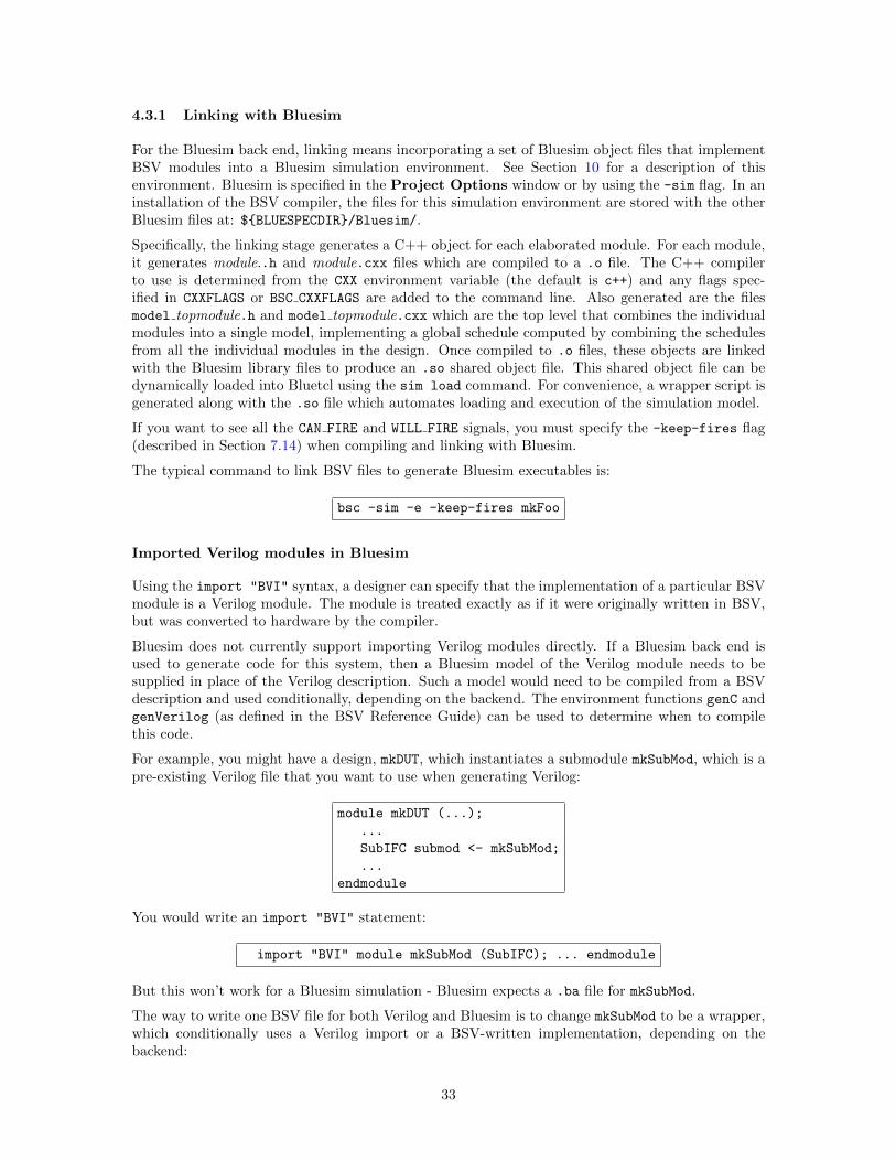
For example, you might have a design, mkDUT, which instantiates a submodule mkSubMod, which is apre-existing Verilog file that you want to use when generating Verilog:
module mkDUT (...);
...
SubIFC submod <- mkSubMod;
...
endmodule
You would write an import "BVI" statement:
import "BVI" module mkSubMod (SubIFC); ... endmodule
But this won’t work for a Bluesim simulation - Bluesim expects a .ba file for mkSubMod.
The way to write one BSV file for both Verilog and Bluesim is to change mkSubMod to be a wrapper,which conditionally uses a Verilog import or a BSV-written implementation, depending on thebackend:
33
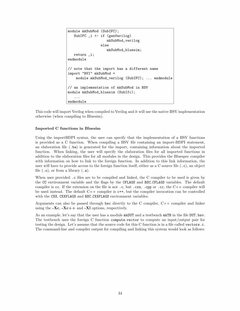
module mkSubMod (SubIFC);
SubIFC _i <- if (genVerilog)
mkSubMod_verilog
else
mkSubMod_bluesim;
return _i;
endmodule
// note that the import has a different name
import "BVI" mkSubMod =
module mkSubMod_verilog (SubIFC); ... endmodule
// an implementation of mkSubMod in BSV
module mkSubMod_bluesim (SubIfc);
...
endmodule
This code will import Verilog when compiled to Verilog and it will use the native BSV implementationotherwise (when compiling to Bluesim).
Imported C functions in Bluesim
Using the importBDPI syntax, the user can specify that the implementation of a BSV functionsis provided as a C function. When compiling a BSV file containing an import-BDPI statement,an elaboration file (.ba) is generated for the import, containing information about the importedfunction. When linking, the user will specify the elaboration files for all imported functions inaddition to the elaboration files for all modules in the design. This provides the Bluespec compilerwith information on how to link to the foreign function. In addition to this link information, theuser will have to provide access to the foreign function itself, either as a C source file (.c), an objectfile (.o), or from a library (.a).
When user provided .c files are to be compiled and linked, the C compiler to be used is given bythe CC environment variable and the flags by the CFLAGS and BSC CFLAGS variables. The defaultcompiler is cc. If the extension on the file is not .c, but .cxx, .cpp or .cc, the C++ compiler willbe used instead. The default C++ compiler is c++, but the compiler invocation can be controlledwith the CXX, CXXFLAGS and BSC CXXFLAGS environment variables.
Arguments can also be passed through bsc directly to the C compiler, C++ compiler and linkerusing the -Xc, -Xc++ and -Xl options, respectively.
As an example, let’s say that the user has a module mkDUT and a testbench mkTB in the file DUT.bsv.The testbench uses the foreign C function compute vector to compute an input/output pair fortesting the design. Let’s assume that the source code for this C function is in a file called vectors.c.The command-line and compiler output for compiling and linking this system would look as follows:
34
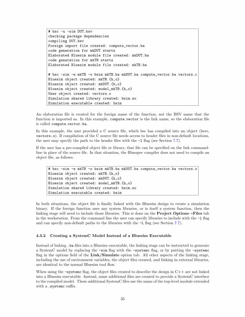
# bsc -u -sim DUT.bsv
checking package dependencies
compiling DUT.bsv
Foreign import file created: compute_vector.ba
code generation for mkDUT starts
Elaborated Bluesim module file created: mkDUT.ba
code generation for mkTB starts
Elaborated Bluesim module file created: mkTB.ba
# bsc -sim -e mkTB -o bsim mkTB.ba mkDUT.ba compute_vector.ba vectors.c
Bluesim object created: mkTB.{h,o}
Bluesim object created: mkDUT.{h,o}
Bluesim object created: model_mkTB.{h,o}
User object created: vectors.o
Simulation shared library created: bsim.so
Simulation executable created: bsim
An elaboration file is created for the foreign name of the function, not the BSV name that thefunction is imported as. In this example, compute vector is the link name, so the elaboration fileis called compute vector.ba.
In this example, the user provided a C source file, which bsc has compiled into an object (here,vectors.o). If compilation of the C source file needs access to header files in non-default locations,the user may specify the path to the header files with the -I flag (see Section 7.7).
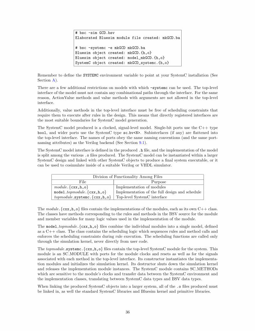
If the user has a pre-compiled object file or library, that file can be specified on the link command-line in place of the source file. In that situation, the Bluespec compiler does not need to compile anobject file, as follows:
# bsc -sim -e mkTB -o bsim mkTB.ba mkDUT.ba compute_vector.ba vectors.o
Bluesim object created: mkTB.{h,o}
Bluesim object created: mkDUT.{h,o}
Bluesim object created: model_mkTB.{h,o}
Simulation shared library created: bsim.so
Simulation executable created: bsim
In both situations, the object file is finally linked with the Bluesim design to create a simulationbinary. If the foreign function uses any system libraries, or is itself a system function, then thelinking stage will need to include those libraries. This is done on the Project Options→Files tabin the workstation. From the command line the user can specify libraries to include with the -l flagand can specify non-default paths to the libraries with the -L flag (see Section 7.7).
4.3.2 Creating a SystemC Model Instead of a Bluesim Executable
Instead of linking .ba files into a Bluesim executable, the linking stage can be instructed to generatea SystemC model by replacing the -sim flag with the -systemc flag, or by putting the -systemc
flag in the options field of the Link/Simulate option tab. All other aspects of the linking stage,including the use of environment variables, the object files created, and linking in external libraries,are identical to the normal Bluesim tool flow.
When using the -systemc flag, the object files created to describe the design in C++ are not linkedinto a Bluesim executable. Instead, some additional files are created to provide a SystemC interfaceto the compiled model. These additional SystemC files use the name of the top-level module extendedwith a systemc suffix.
35
# bsc -sim GCD.bsv
Elaborated Bluesim module file created: mkGCD.ba
# bsc -systemc -e mkGCD mkGCD.ba
Bluesim object created: mkGCD.{h,o}
Bluesim object created: model_mkGCD.{h,o}
SystemC object created: mkGCD_systemc.{h,o}
Remember to define the SYSTEMC environment variable to point at your SystemC installation (SeeSection A).
There are a few additional restrictions on models with which -systemc can be used. The top-levelinterface of the model must not contain any combinational paths through the interface. For the samereason, ActionValue methods and value methods with arguments are not allowed in the top-levelinterface.
Additionally, value methods in the top-level interface must be free of scheduling constraints thatrequire them to execute after rules in the design. This means that directly registered interfaces arethe most suitable boundaries for SystemC model generation.
The SystemC model produced is a clocked, signal-level model. Single-bit ports use the C++ typebool, and wider ports use the SystemC type sc bv<N>. Subinterfaces (if any) are flattened intothe top-level interface. The names of ports obey the same naming conventions (and the same port-naming attributes) as the Verilog backend (See Section 9.1).
The SystemC model interface is defined in the produced .h file, and the implementation of the modelis split among the various .o files produced. The SystemC model can be instantiated within a largerSystemC design and linked with other SystemC objects to produce a final system executable, or itcan be used to cosimulate inside of a suitable Verilog or VHDL simulator.
Division of Functionality Among FilesFile Purpose
module.{cxx,h,o} Implementation of modulesmodel topmodule.{cxx,h,o} Implementation of the full design and scheduletopmodule systemc.{cxx,h,o} Top-level SystemC interface
The module.{cxx,h,o} files contain the implementations of the modules, each as its own C++ class.The classes have methods corresponding to the rules and methods in the BSV source for the moduleand member variables for many logic values used in the implementation of the module.
The model topmodule.{cxx,h,o} files combine the individual modules into a single model, definedas a C++ class. The class contains the scheduling logic which sequences rules and method calls andenforces the scheduling constraints during rule execution. The scheduling functions are called onlythrough the simulation kernel, never directly from user code.
The topmodule systemc.{cxx,h,o} files contain the top-level SystemC module for the system. Thismodule is an SC MODULE with ports for the module clocks and resets as well as for the signalsassociated with each method in the top-level interface. Its constructor instantiates the implementa-tion modules and initializes the simulation kernel. Its destructor shuts down the simulation kerneland releases the implementation module instances. The SystemC module contains SC METHODswhich are sensitive to the module’s clocks and transfer data between the SystemC environment andthe implementation classes, translating between SystemC data types and BSV data types.
When linking the produced SystemC objects into a larger system, all of the .o files produced mustbe linked in, as well the standard SystemC libraries and Bluesim kernel and primitive libraries.
36
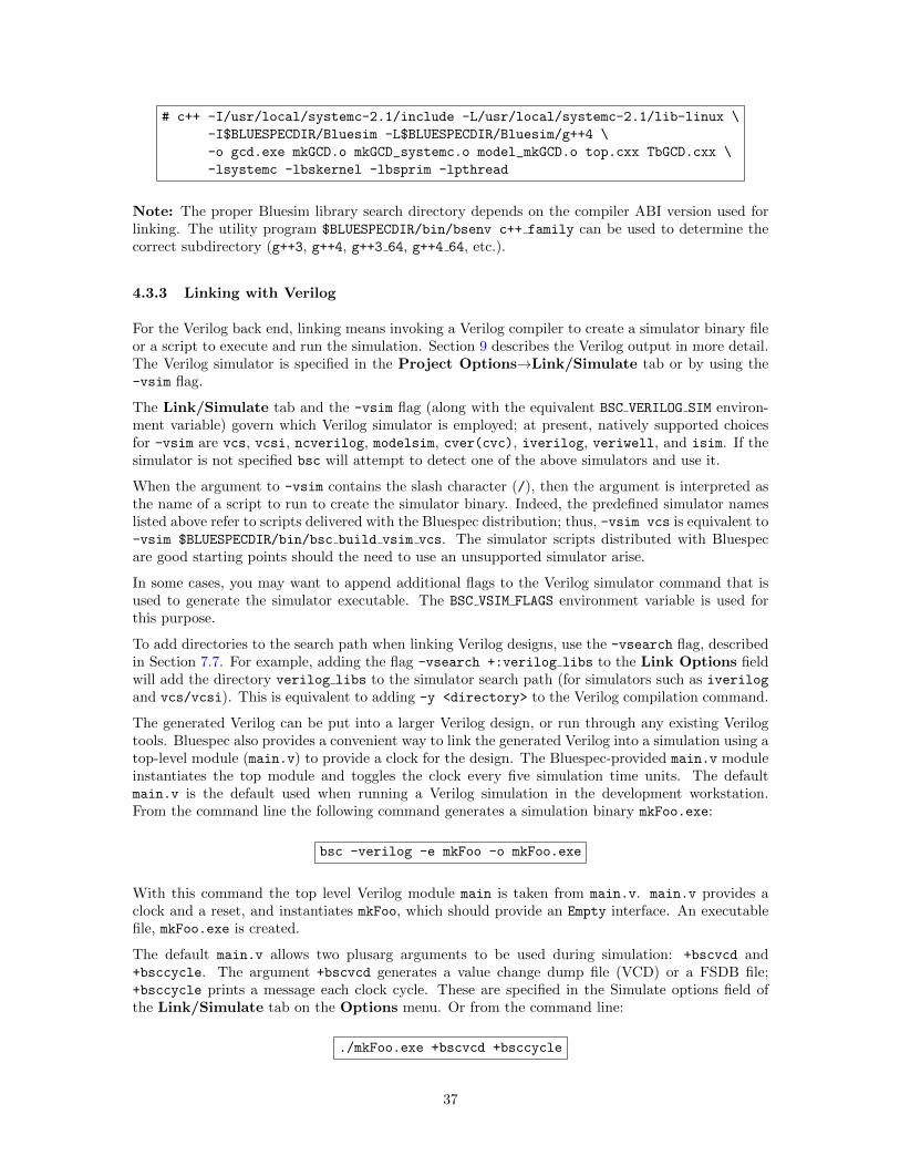
# c++ -I/usr/local/systemc-2.1/include -L/usr/local/systemc-2.1/lib-linux \
-I$BLUESPECDIR/Bluesim -L$BLUESPECDIR/Bluesim/g++4 \
-o gcd.exe mkGCD.o mkGCD_systemc.o model_mkGCD.o top.cxx TbGCD.cxx \
-lsystemc -lbskernel -lbsprim -lpthread
Note: The proper Bluesim library search directory depends on the compiler ABI version used forlinking. The utility program $BLUESPECDIR/bin/bsenv c++ family can be used to determine thecorrect subdirectory (g++3, g++4, g++3 64, g++4 64, etc.).
4.3.3 Linking with Verilog
For the Verilog back end, linking means invoking a Verilog compiler to create a simulator binary fileor a script to execute and run the simulation. Section 9 describes the Verilog output in more detail.The Verilog simulator is specified in the Project Options→Link/Simulate tab or by using the-vsim flag.
The Link/Simulate tab and the -vsim flag (along with the equivalent BSC VERILOG SIM environ-ment variable) govern which Verilog simulator is employed; at present, natively supported choicesfor -vsim are vcs, vcsi, ncverilog, modelsim, cver(cvc), iverilog, veriwell, and isim. If thesimulator is not specified bsc will attempt to detect one of the above simulators and use it.
When the argument to -vsim contains the slash character (/), then the argument is interpreted asthe name of a script to run to create the simulator binary. Indeed, the predefined simulator nameslisted above refer to scripts delivered with the Bluespec distribution; thus, -vsim vcs is equivalent to-vsim $BLUESPECDIR/bin/bsc build vsim vcs. The simulator scripts distributed with Bluespecare good starting points should the need to use an unsupported simulator arise.
In some cases, you may want to append additional flags to the Verilog simulator command that isused to generate the simulator executable. The BSC VSIM FLAGS environment variable is used forthis purpose.
To add directories to the search path when linking Verilog designs, use the -vsearch flag, describedin Section 7.7. For example, adding the flag -vsearch +:verilog libs to the Link Options fieldwill add the directory verilog libs to the simulator search path (for simulators such as iverilogand vcs/vcsi). This is equivalent to adding -y <directory> to the Verilog compilation command.
The generated Verilog can be put into a larger Verilog design, or run through any existing Verilogtools. Bluespec also provides a convenient way to link the generated Verilog into a simulation using atop-level module (main.v) to provide a clock for the design. The Bluespec-provided main.v moduleinstantiates the top module and toggles the clock every five simulation time units. The defaultmain.v is the default used when running a Verilog simulation in the development workstation.From the command line the following command generates a simulation binary mkFoo.exe:
bsc -verilog -e mkFoo -o mkFoo.exe
With this command the top level Verilog module main is taken from main.v. main.v provides aclock and a reset, and instantiates mkFoo, which should provide an Empty interface. An executablefile, mkFoo.exe is created.
The default main.v allows two plusarg arguments to be used during simulation: +bscvcd and+bsccycle. The argument +bscvcd generates a value change dump file (VCD) or a FSDB file;+bsccycle prints a message each clock cycle. These are specified in the Simulate options field ofthe Link/Simulate tab on the Options menu. Or from the command line:
./mkFoo.exe +bscvcd +bsccycle
37
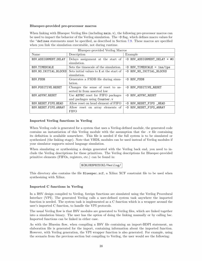
Bluespec-provided pre-processor macros
When linking with Bluespec Verilog files (including main.v), the following pre-processor macros canbe used to impact the behavior of the Verilog simulation. The -D flag, which defines macro values forthe ‘defines statements must be specified, as described in Section 7.9. These macros are specifiedwhen you link the simulation executable, not during runtime.
Bluespec-provided Verilog MacrosName Description Example
BSV ASSIGNMENT DELAY Delays assignment at the start ofsimulation.
-D BSV_ASSIGNMENT_DELAY = #0
BSV TIMESCALE Sets the timescale of the simulation. -D BSV_TIMESCALE = 1ns/1ps
BSV NO INITIAL BLOCKS Sets initial values to X at the start ofsimulation.
-D BSV_NO_INITIAL_BLOCKS
BSV FSDB Generates a FSDB file during simu-lation.
-D BSV_FSDB
BSV POSITIVE RESET Changes the sense of reset to as-serted hi from asserted low
-D BSV_POSITIVE_RESET
BSV ASYNC RESET Use ASYNC reset for FIFO packagesand packages using Counter.v
-D BSV_ASYNC_RESET
BSV RESET FIFO HEAD Allow reset on head element of FIFO -D BSV_RESET_FIFO _HEAD
BSV RESET FIFO ARRAY Allow reset on array elements ofFIFO
-D BSV_RESET_FIFO_ARRAY
Imported Verilog functions in Verilog
When Verilog code is generated for a system that uses a Verilog-defined module, the generated codecontains an instantiation of this Verilog module with the assumption that the .v file containingits definition is available somewhere. This file is needed if the full system is to be simulated orsynthesized (the linking stage). Note that VHDL modules can be used instead of Verilog modules ifyour simulator supports mixed language simulation.
When simulating or synthesizing a design generated with the Verilog back end, you need to in-clude the Verilog descriptions for these primitives. The Verilog descriptions for Bluespec-providedprimitive elements (FIFOs, registers, etc.) can be found in:
${BLUESPECDIR}/Verilog/
This directory also contains the file Bluespec.xcf, a Xilinx XCF constraint file to be used whensynthesizing with Xilinx.
Imported C functions in Verilog
In a BSV design compiled to Verilog, foreign functions are simulated using the Verilog ProceduralInterface (VPI). The generated Verilog calls a user-defined system task anywhere the importedfunction is needed. The system task is implemented as a C function which is a wrapper around theuser’s imported C function, to handle the VPI protocols.
The usual Verilog flow is that BSV modules are generated to Verilog files, which are linked togetherinto a simulation binary. The user has the option of doing the linking manually or by calling bsc.Imported functions can be linked in either case.
As with the Bluesim flow, when compiling a BSV file containing an import-BDPI statement, anelaboration file is generated for the import, containing information about the imported function.However, with Verilog generation, the VPI wrapper function is also generated. For example, usingthe scenario from the previous section but compiling to Verilog, the user would see the following:
38
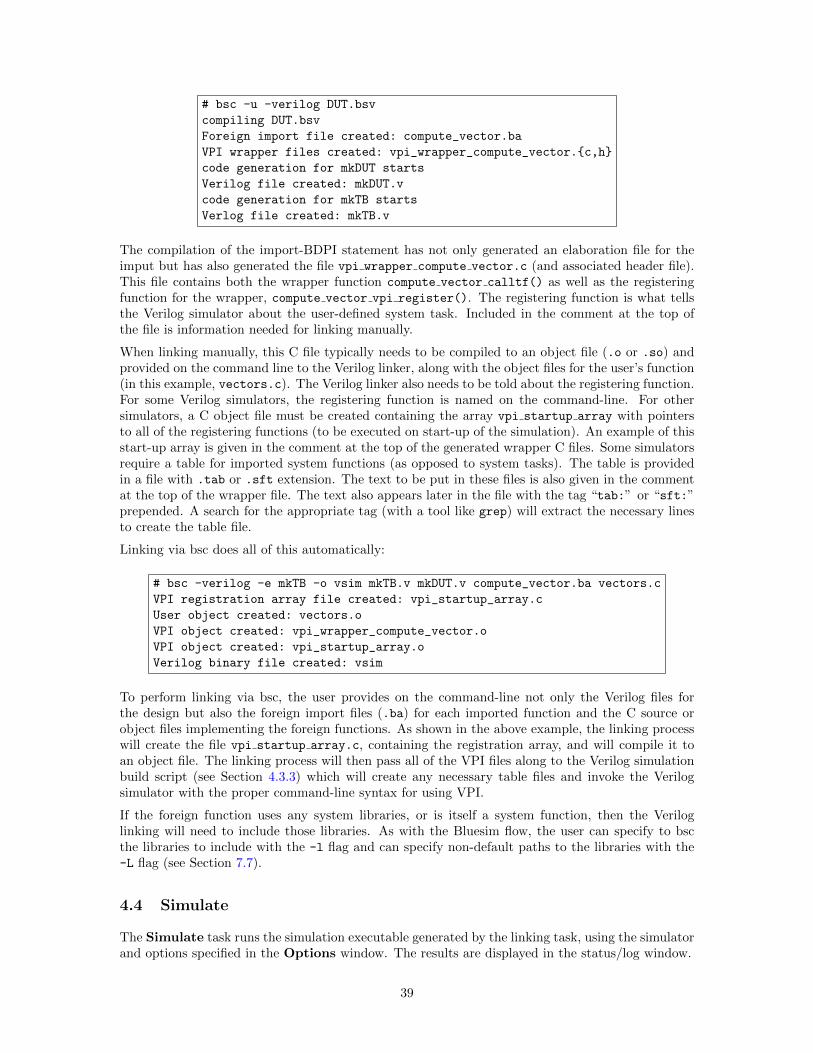
# bsc -u -verilog DUT.bsv
compiling DUT.bsv
Foreign import file created: compute_vector.ba
VPI wrapper files created: vpi_wrapper_compute_vector.{c,h}
code generation for mkDUT starts
Verilog file created: mkDUT.v
code generation for mkTB starts
Verlog file created: mkTB.v
The compilation of the import-BDPI statement has not only generated an elaboration file for theimput but has also generated the file vpi wrapper compute vector.c (and associated header file).This file contains both the wrapper function compute vector calltf() as well as the registeringfunction for the wrapper, compute vector vpi register(). The registering function is what tellsthe Verilog simulator about the user-defined system task. Included in the comment at the top ofthe file is information needed for linking manually.
When linking manually, this C file typically needs to be compiled to an object file (.o or .so) andprovided on the command line to the Verilog linker, along with the object files for the user’s function(in this example, vectors.c). The Verilog linker also needs to be told about the registering function.For some Verilog simulators, the registering function is named on the command-line. For othersimulators, a C object file must be created containing the array vpi startup array with pointersto all of the registering functions (to be executed on start-up of the simulation). An example of thisstart-up array is given in the comment at the top of the generated wrapper C files. Some simulatorsrequire a table for imported system functions (as opposed to system tasks). The table is providedin a file with .tab or .sft extension. The text to be put in these files is also given in the commentat the top of the wrapper file. The text also appears later in the file with the tag “tab:” or “sft:”prepended. A search for the appropriate tag (with a tool like grep) will extract the necessary linesto create the table file.
Linking via bsc does all of this automatically:
# bsc -verilog -e mkTB -o vsim mkTB.v mkDUT.v compute_vector.ba vectors.c
VPI registration array file created: vpi_startup_array.c
User object created: vectors.o
VPI object created: vpi_wrapper_compute_vector.o
VPI object created: vpi_startup_array.o
Verilog binary file created: vsim
To perform linking via bsc, the user provides on the command-line not only the Verilog files forthe design but also the foreign import files (.ba) for each imported function and the C source orobject files implementing the foreign functions. As shown in the above example, the linking processwill create the file vpi startup array.c, containing the registration array, and will compile it toan object file. The linking process will then pass all of the VPI files along to the Verilog simulationbuild script (see Section 4.3.3) which will create any necessary table files and invoke the Verilogsimulator with the proper command-line syntax for using VPI.
If the foreign function uses any system libraries, or is itself a system function, then the Veriloglinking will need to include those libraries. As with the Bluesim flow, the user can specify to bscthe libraries to include with the -l flag and can specify non-default paths to the libraries with the-L flag (see Section 7.7).
4.4 Simulate
The Simulate task runs the simulation executable generated by the linking task, using the simulatorand options specified in the Options window. The results are displayed in the status/log window.
39
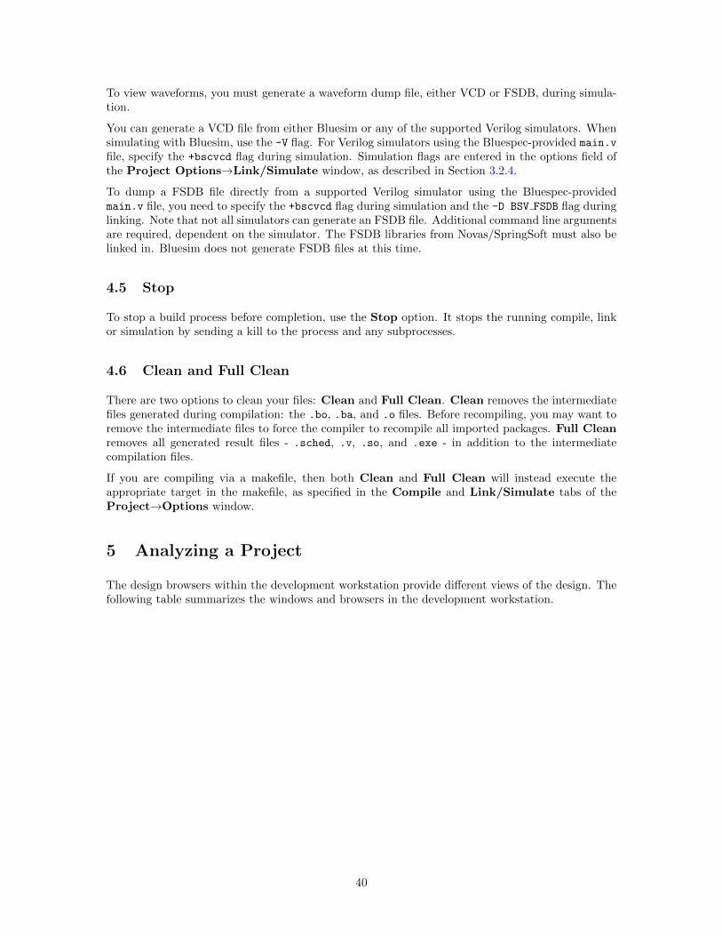
To view waveforms, you must generate a waveform dump file, either VCD or FSDB, during simula-tion.
You can generate a VCD file from either Bluesim or any of the supported Verilog simulators. Whensimulating with Bluesim, use the -V flag. For Verilog simulators using the Bluespec-provided main.v
file, specify the +bscvcd flag during simulation. Simulation flags are entered in the options field ofthe Project Options→Link/Simulate window, as described in Section 3.2.4.
To dump a FSDB file directly from a supported Verilog simulator using the Bluespec-providedmain.v file, you need to specify the +bscvcd flag during simulation and the -D BSV FSDB flag duringlinking. Note that not all simulators can generate an FSDB file. Additional command line argumentsare required, dependent on the simulator. The FSDB libraries from Novas/SpringSoft must also belinked in. Bluesim does not generate FSDB files at this time.
4.5 Stop
To stop a build process before completion, use the Stop option. It stops the running compile, linkor simulation by sending a kill to the process and any subprocesses.
4.6 Clean and Full Clean
There are two options to clean your files: Clean and Full Clean. Clean removes the intermediatefiles generated during compilation: the .bo, .ba, and .o files. Before recompiling, you may want toremove the intermediate files to force the compiler to recompile all imported packages. Full Cleanremoves all generated result files - .sched, .v, .so, and .exe - in addition to the intermediatecompilation files.
If you are compiling via a makefile, then both Clean and Full Clean will instead execute theappropriate target in the makefile, as specified in the Compile and Link/Simulate tabs of theProject→Options window.
5 Analyzing a Project
The design browsers within the development workstation provide different views of the design. Thefollowing table summarizes the windows and browsers in the development workstation.
40
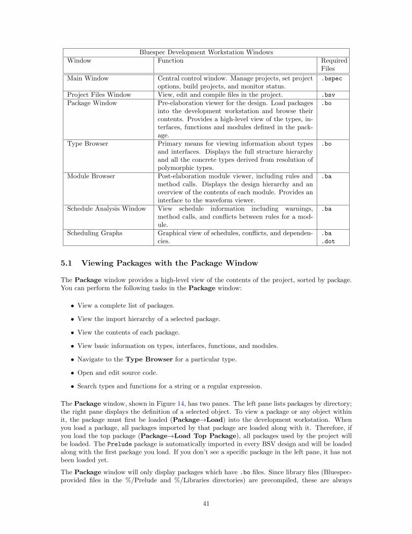
Bluespec Development Workstation WindowsWindow Function Required
Files
Main Window Central control window. Manage projects, set projectoptions, build projects, and monitor status.
.bspec
Project Files Window View, edit and compile files in the project. .bsv
Package Window Pre-elaboration viewer for the design. Load packagesinto the development workstation and browse theircontents. Provides a high-level view of the types, in-terfaces, functions and modules defined in the pack-age.
.bo
Type Browser Primary means for viewing information about typesand interfaces. Displays the full structure hierarchyand all the concrete types derived from resolution ofpolymorphic types.
.bo
Module Browser Post-elaboration module viewer, including rules andmethod calls. Displays the design hierarchy and anoverview of the contents of each module. Provides aninterface to the waveform viewer.
.ba
Schedule Analysis Window View schedule information including warnings,method calls, and conflicts between rules for a mod-ule.
.ba
Scheduling Graphs Graphical view of schedules, conflicts, and dependen-cies.
.ba
.dot
5.1 Viewing Packages with the Package Window
The Package window provides a high-level view of the contents of the project, sorted by package.You can perform the following tasks in the Package window:
• View a complete list of packages.
• View the import hierarchy of a selected package.
• View the contents of each package.
• View basic information on types, interfaces, functions, and modules.
• Navigate to the Type Browser for a particular type.
• Open and edit source code.
• Search types and functions for a string or a regular expression.
The Package window, shown in Figure 14, has two panes. The left pane lists packages by directory;the right pane displays the definition of a selected object. To view a package or any object withinit, the package must first be loaded (Package→Load) into the development workstation. Whenyou load a package, all packages imported by that package are loaded along with it. Therefore, ifyou load the top package (Package→Load Top Package), all packages used by the project willbe loaded. The Prelude package is automatically imported in every BSV design and will be loadedalong with the first package you load. If you don’t see a specific package in the left pane, it has notbeen loaded yet.
The Package window will only display packages which have .bo files. Since library files (Bluespec-provided files in the %/Prelude and %/Libraries directories) are precompiled, these are always
41
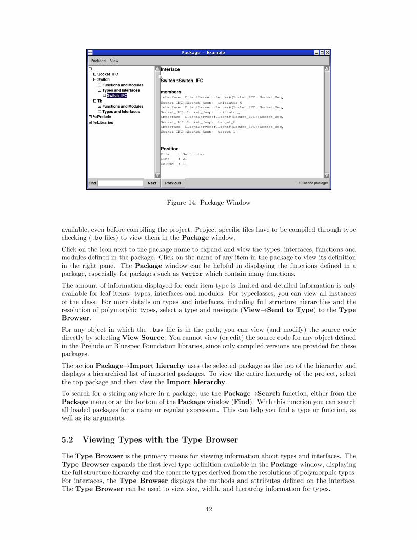
Figure 14: Package Window
available, even before compiling the project. Project specific files have to be compiled through typechecking (.bo files) to view them in the Package window.
Click on the icon next to the package name to expand and view the types, interfaces, functions andmodules defined in the package. Click on the name of any item in the package to view its definitionin the right pane. The Package window can be helpful in displaying the functions defined in apackage, especially for packages such as Vector which contain many functions.
The amount of information displayed for each item type is limited and detailed information is onlyavailable for leaf items: types, interfaces and modules. For typeclasses, you can view all instancesof the class. For more details on types and interfaces, including full structure hierarchies and theresolution of polymorphic types, select a type and navigate (View→Send to Type) to the TypeBrowser.
For any object in which the .bsv file is in the path, you can view (and modify) the source codedirectly by selecting View Source. You cannot view (or edit) the source code for any object definedin the Prelude or Bluespec Foundation libraries, since only compiled versions are provided for thesepackages.
The action Package→Import hierachy uses the selected package as the top of the hierarchy anddisplays a hierarchical list of imported packages. To view the entire hierarchy of the project, selectthe top package and then view the Import hierarchy.
To search for a string anywhere in a package, use the Package→Search function, either from thePackage menu or at the bottom of the Package window (Find). With this function you can searchall loaded packages for a name or regular expression. This can help you find a type or function, aswell as its arguments.
5.2 Viewing Types with the Type Browser
The Type Browser is the primary means for viewing information about types and interfaces. TheType Browser expands the first-level type definition available in the Package window, displayingthe full structure hierarchy and the concrete types derived from the resolutions of polymorphic types.For interfaces, the Type Browser displays the methods and attributes defined on the interface.The Type Browser can be used to view size, width, and hierarchy information for types.
42
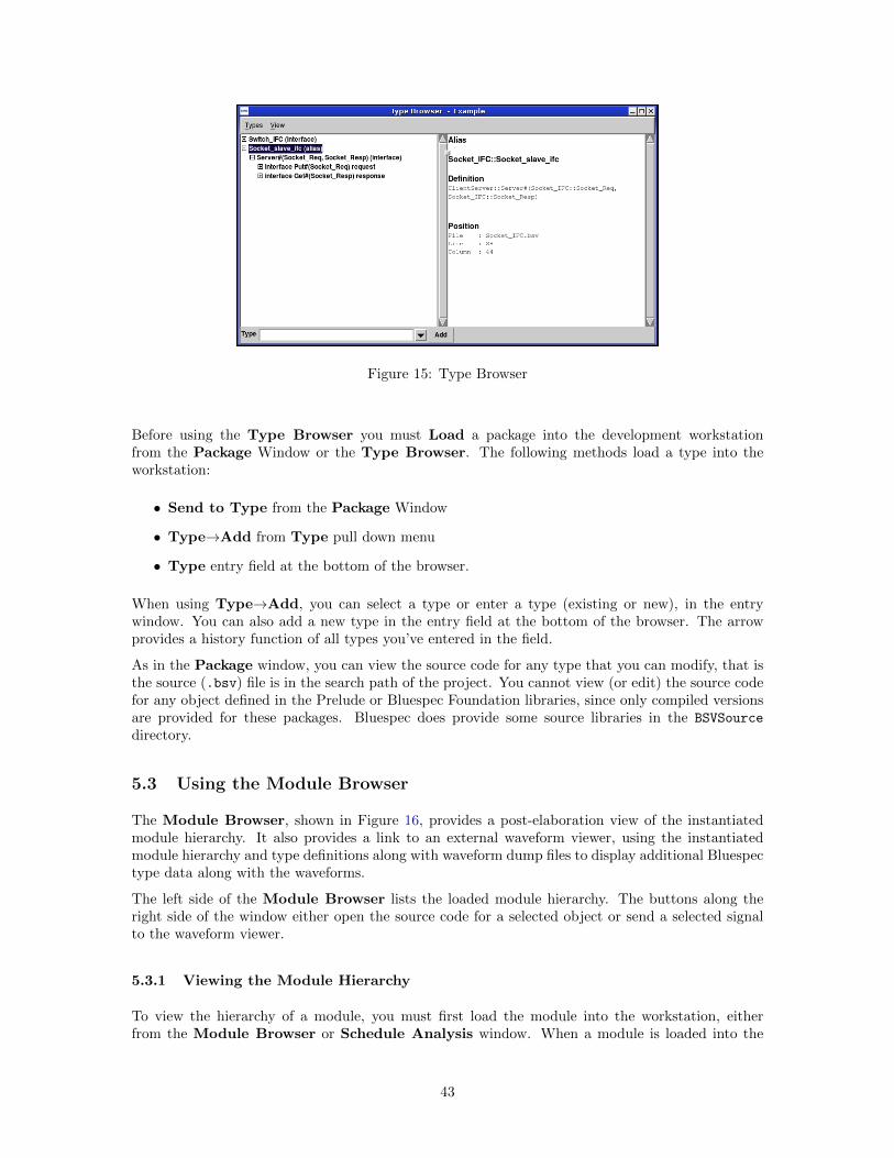
Figure 15: Type Browser
Before using the Type Browser you must Load a package into the development workstationfrom the Package Window or the Type Browser. The following methods load a type into theworkstation:
• Send to Type from the Package Window
• Type→Add from Type pull down menu
• Type entry field at the bottom of the browser.
When using Type→Add, you can select a type or enter a type (existing or new), in the entrywindow. You can also add a new type in the entry field at the bottom of the browser. The arrowprovides a history function of all types you’ve entered in the field.
As in the Package window, you can view the source code for any type that you can modify, that isthe source (.bsv) file is in the search path of the project. You cannot view (or edit) the source codefor any object defined in the Prelude or Bluespec Foundation libraries, since only compiled versionsare provided for these packages. Bluespec does provide some source libraries in the BSVSource
directory.
5.3 Using the Module Browser
The Module Browser, shown in Figure 16, provides a post-elaboration view of the instantiatedmodule hierarchy. It also provides a link to an external waveform viewer, using the instantiatedmodule hierarchy and type definitions along with waveform dump files to display additional Bluespectype data along with the waveforms.
The left side of the Module Browser lists the loaded module hierarchy. The buttons along theright side of the window either open the source code for a selected object or send a selected signalto the waveform viewer.
5.3.1 Viewing the Module Hierarchy
To view the hierarchy of a module, you must first load the module into the workstation, eitherfrom the Module Browser or Schedule Analysis window. When a module is loaded into the
43
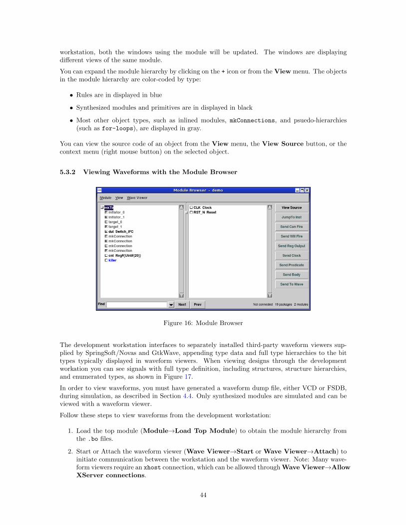
workstation, both the windows using the module will be updated. The windows are displayingdifferent views of the same module.
You can expand the module hierarchy by clicking on the + icon or from the View menu. The objectsin the module hierarchy are color-coded by type:
• Rules are in displayed in blue
• Synthesized modules and primitives are in displayed in black
• Most other object types, such as inlined modules, mkConnections, and psuedo-hierarchies(such as for-loops), are displayed in gray.
You can view the source code of an object from the View menu, the View Source button, or thecontext menu (right mouse button) on the selected object.
5.3.2 Viewing Waveforms with the Module Browser
Figure 16: Module Browser
The development workstation interfaces to separately installed third-party waveform viewers sup-plied by SpringSoft/Novas and GtkWave, appending type data and full type hierarchies to the bittypes typically displayed in waveform viewers. When viewing designs through the developmentworkation you can see signals with full type definition, including structures, structure hierarchies,and enumerated types, as shown in Figure 17.
In order to view waveforms, you must have generated a waveform dump file, either VCD or FSDB,during simulation, as described in Section 4.4. Only synthesized modules are simulated and can beviewed with a waveform viewer.
Follow these steps to view waveforms from the development workstation:
1. Load the top module (Module→Load Top Module) to obtain the module hierarchy fromthe .bo files.
2. Start or Attach the waveform viewer (Wave Viewer→Start or Wave Viewer→Attach) toinitiate communication between the workstation and the waveform viewer. Note: Many wave-form viewers require an xhost connection, which can be allowed through Wave Viewer→AllowXServer connections.
44
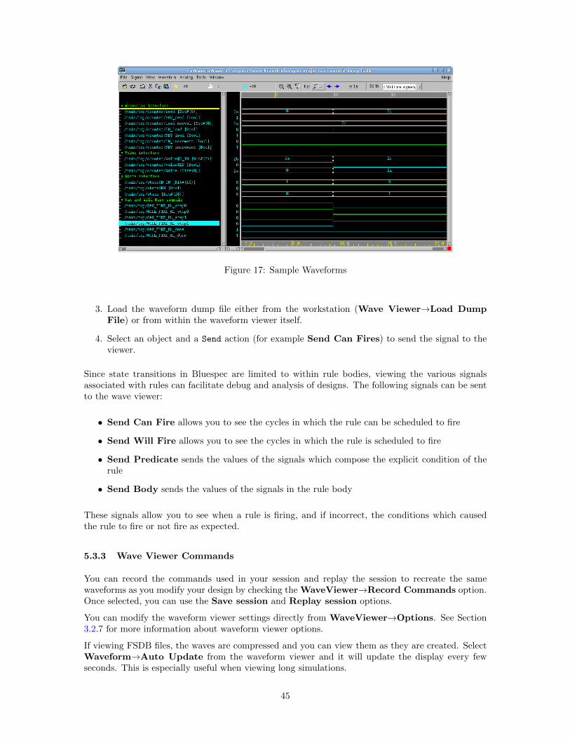
Figure 17: Sample Waveforms
3. Load the waveform dump file either from the workstation (Wave Viewer→Load DumpFile) or from within the waveform viewer itself.
4. Select an object and a Send action (for example Send Can Fires) to send the signal to theviewer.
Since state transitions in Bluespec are limited to within rule bodies, viewing the various signalsassociated with rules can facilitate debug and analysis of designs. The following signals can be sentto the wave viewer:
• Send Can Fire allows you to see the cycles in which the rule can be scheduled to fire
• Send Will Fire allows you to see the cycles in which the rule is scheduled to fire
• Send Predicate sends the values of the signals which compose the explicit condition of therule
• Send Body sends the values of the signals in the rule body
These signals allow you to see when a rule is firing, and if incorrect, the conditions which causedthe rule to fire or not fire as expected.
5.3.3 Wave Viewer Commands
You can record the commands used in your session and replay the session to recreate the samewaveforms as you modify your design by checking the WaveViewer→Record Commands option.Once selected, you can use the Save session and Replay session options.
You can modify the waveform viewer settings directly from WaveViewer→Options. See Section3.2.7 for more information about waveform viewer options.
If viewing FSDB files, the waves are compressed and you can view them as they are created. SelectWaveform→Auto Update from the waveform viewer and it will update the display every fewseconds. This is especially useful when viewing long simulations.
45
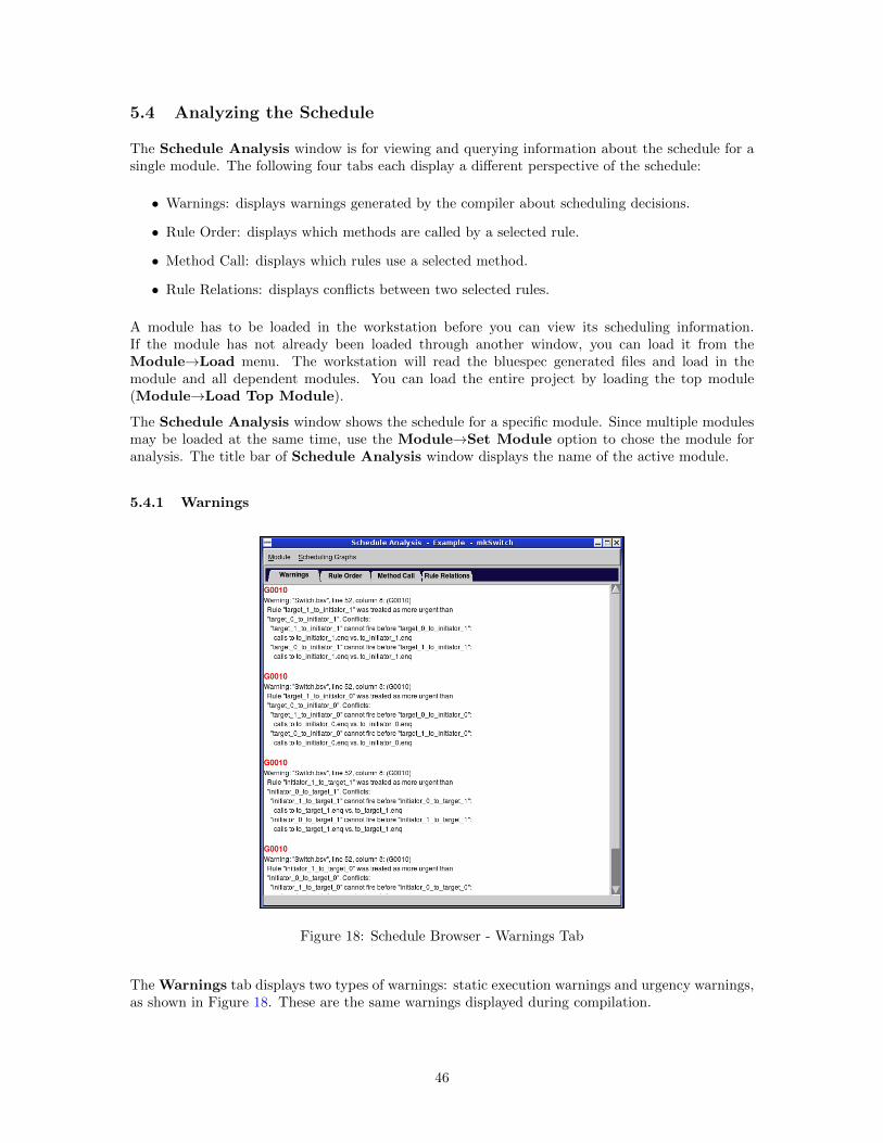
5.4 Analyzing the Schedule
The Schedule Analysis window is for viewing and querying information about the schedule for asingle module. The following four tabs each display a different perspective of the schedule:
• Warnings: displays warnings generated by the compiler about scheduling decisions.
• Rule Order: displays which methods are called by a selected rule.
• Method Call: displays which rules use a selected method.
• Rule Relations: displays conflicts between two selected rules.
A module has to be loaded in the workstation before you can view its scheduling information.If the module has not already been loaded through another window, you can load it from theModule→Load menu. The workstation will read the bluespec generated files and load in themodule and all dependent modules. You can load the entire project by loading the top module(Module→Load Top Module).
The Schedule Analysis window shows the schedule for a specific module. Since multiple modulesmay be loaded at the same time, use the Module→Set Module option to chose the module foranalysis. The title bar of Schedule Analysis window displays the name of the active module.
5.4.1 Warnings
Figure 18: Schedule Browser - Warnings Tab
The Warnings tab displays two types of warnings: static execution warnings and urgency warnings,as shown in Figure 18. These are the same warnings displayed during compilation.
46
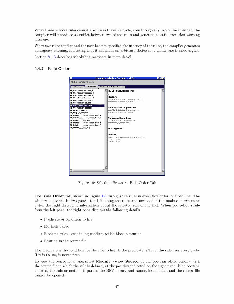
When three or more rules cannot execute in the same cycle, even though any two of the rules can, thecompiler will introduce a conflict between two of the rules and generate a static execution warningmessage.
When two rules conflict and the user has not specified the urgency of the rules, the compiler generatesan urgency warning, indicating that it has made an arbitrary choice as to which rule is more urgent.
Section 8.1.3 describes scheduling messages in more detail.
5.4.2 Rule Order
Figure 19: Schedule Browser - Rule Order Tab
The Rule Order tab, shown in Figure 19, displays the rules in execution order, one per line. Thewindow is divided in two panes; the left listing the rules and methods in the module in executionorder, the right displaying information about the selected rule or method. When you select a rulefrom the left pane, the right pane displays the following details:
• Predicate or condition to fire
• Methods called
• Blocking rules - scheduling conflicts which block execution
• Position in the source file
The predicate is the condition for the rule to fire. If the predicate is True, the rule fires every cycle.If it is False, it never fires.
To view the source for a rule, select Module→View Source. It will open an editor window withthe source file in which the rule is defined, at the position indicated on the right pane. If no positionis listed, the rule or method is part of the BSV library and cannot be modified and the source filecannot be opened.
47
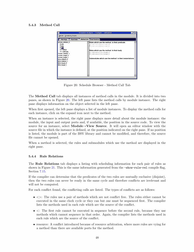
5.4.3 Method Call
Figure 20: Schedule Browser - Method Call Tab
The Method Call tab displays all instances of method calls in the module. It is divided into twopanes, as shown in Figure 20. The left pane lists the method calls by module instance. The rightpane displays information on the object selected in the left pane.
When first opened, the left pane displays a list of module instances. To display the method calls foreach instance, click on the expand icon next to the method.
When an instance is selected, the right pane displays more detail about the module instance: themodule, the input and output ports and, if available, the position in the source code. To view thesource for an instance, select Module→View Source. It will open an editor window with thesource file in which the instance is defined, at the position indicated on the right pane. If no positionis listed, the module is part of the BSV library and cannot be modified, and therefore, the sourcefile cannot be opened.
When a method is selected, the rules and submodules which use the method are displayed in theright pane.
5.4.4 Rule Relations
The Rule Relations tab displays a listing with scheduling information for each pair of rules asshown in Figure 21. This is the same information generated from the -show-rule-rel compile flag,Section 7.15.
If the compiler can determine that the predicates of the two rules are mutually exclusive (disjoint),then the two rules can never be ready in the same cycle and therefore conflicts are irrelevant andwill not be computed.
For each conflict found, the conflicting calls are listed. The types of conflicts are as follows:
• <>: The rules use a pair of methods which are not conflict free. The rules either cannot beexecuted in the same clock cycle or they can but one must be sequenced first. The compilerlists the methods used in each rule which are the source of the conflict.
• <: The first rule cannot be executed in sequence before the second rule, because they usemethods which cannot sequence in that order. Again, the compiler lists the methods used ineach rule which are the source of the conflict.
• resource: A conflict introduced because of resource arbitration, where more rules are vying fora method than there are available ports for the method.
48
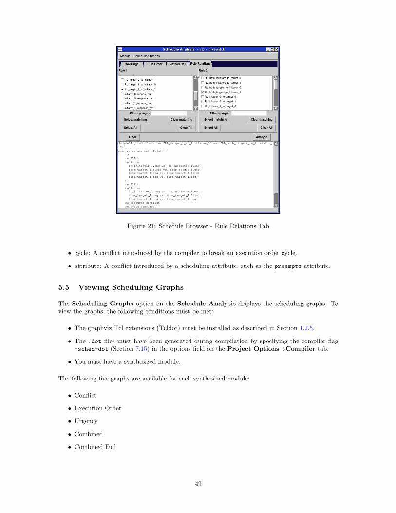
Figure 21: Schedule Browser - Rule Relations Tab
• cycle: A conflict introduced by the compiler to break an execution order cycle.
• attribute: A conflict introduced by a scheduling attribute, such as the preempts attribute.
5.5 Viewing Scheduling Graphs
The Scheduling Graphs option on the Schedule Analysis displays the scheduling graphs. Toview the graphs, the following conditions must be met:
• The graphviz Tcl extensions (Tcldot) must be installed as described in Section 1.2.5.
• The .dot files must have been generated during compilation by specifying the compiler flag-sched-dot (Section 7.15) in the options field on the Project Options→Compiler tab.
• You must have a synthesized module.
The following five graphs are available for each synthesized module:
• Conflict
• Execution Order
• Urgency
• Combined
• Combined Full
49
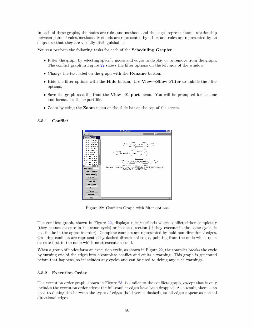
In each of these graphs, the nodes are rules and methods and the edges represent some relationshipbetween pairs of rules/methods. Methods are represented by a box and rules are represented by anellipse, so that they are visually distinguishable.
You can perform the following tasks for each of the Scheduling Graphs:
• Filter the graph by selecting specific nodes and edges to display or to remove from the graph.The conflict graph in Figure 22 shows the filter options on the left side of the window.
• Change the text label on the graph with the Rename button.
• Hide the filter options with the Hide button. Use View→Show Filter to unhide the filteroptions.
• Save the graph as a file from the View→Export menu. You will be prompted for a nameand format for the export file.
• Zoom by using the Zoom menu or the slide bar at the top of the screen.
5.5.1 Conflict
Figure 22: Conflicts Graph with filter options
The conflicts graph, shown in Figure 22, displays rules/methods which conflict either completely(they cannot execute in the same cycle) or in one direction (if they execute in the same cycle, ithas the be in the opposite order). Complete conflicts are represented by bold non-directional edges.Ordering conflicts are represented by dashed directional edges, pointing from the node which mustexecute first to the node which must execute second.
When a group of nodes form an execution cycle, as shown in Figure 22, the compiler breaks the cycleby turning one of the edges into a complete conflict and emits a warning. This graph is generatedbefore that happens, so it includes any cycles and can be used to debug any such warnings.
5.5.2 Execution Order
The execution order graph, shown in Figure 23, is similar to the conflicts graph, except that it onlyincludes the execution order edges; the full-conflict edges have been dropped. As a result, there is noneed to distinguish between the types of edges (bold versus dashed), so all edges appear as normaldirectional edges.
50
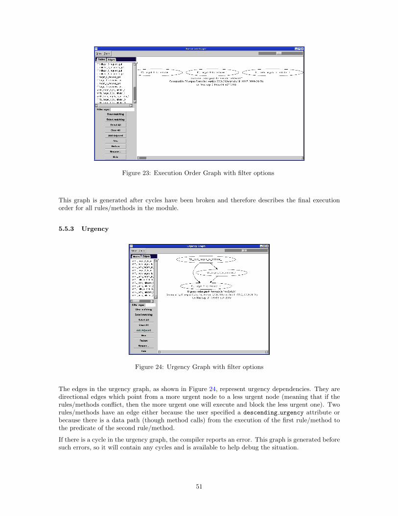
Figure 23: Execution Order Graph with filter options
This graph is generated after cycles have been broken and therefore describes the final executionorder for all rules/methods in the module.
5.5.3 Urgency
Figure 24: Urgency Graph with filter options
The edges in the urgency graph, as shown in Figure 24, represent urgency dependencies. They aredirectional edges which point from a more urgent node to a less urgent node (meaning that if therules/methods conflict, then the more urgent one will execute and block the less urgent one). Tworules/methods have an edge either because the user specified a descending urgency attribute orbecause there is a data path (though method calls) from the execution of the first rule/method tothe predicate of the second rule/method.
If there is a cycle in the urgency graph, the compiler reports an error. This graph is generated beforesuch errors, so it will contain any cycles and is available to help debug the situation.
51
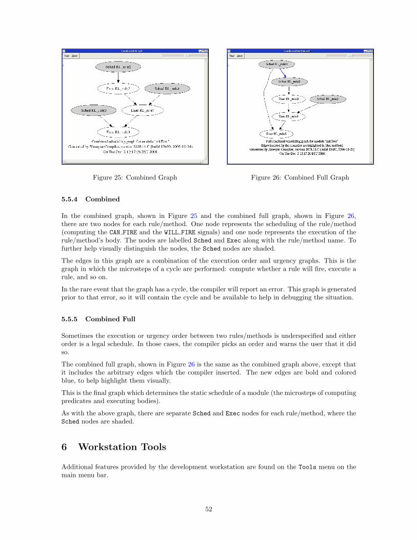
Figure 25: Combined Graph Figure 26: Combined Full Graph
5.5.4 Combined
In the combined graph, shown in Figure 25 and the combined full graph, shown in Figure 26,there are two nodes for each rule/method. One node represents the scheduling of the rule/method(computing the CAN FIRE and the WILL FIRE signals) and one node represents the execution of therule/method’s body. The nodes are labelled Sched and Exec along with the rule/method name. Tofurther help visually distinguish the nodes, the Sched nodes are shaded.
The edges in this graph are a combination of the execution order and urgency graphs. This is thegraph in which the microsteps of a cycle are performed: compute whether a rule will fire, execute arule, and so on.
In the rare event that the graph has a cycle, the compiler will report an error. This graph is generatedprior to that error, so it will contain the cycle and be available to help in debugging the situation.
5.5.5 Combined Full
Sometimes the execution or urgency order between two rules/methods is underspecified and eitherorder is a legal schedule. In those cases, the compiler picks an order and warns the user that it didso.
The combined full graph, shown in Figure 26 is the same as the combined graph above, except thatit includes the arbitrary edges which the compiler inserted. The new edges are bold and coloredblue, to help highlight them visually.
This is the final graph which determines the static schedule of a module (the microsteps of computingpredicates and executing bodies).
As with the above graph, there are separate Sched and Exec nodes for each rule/method, where theSched nodes are shaded.
6 Workstation Tools
Additional features provided by the development workstation are found on the Tools menu on themain menu bar.
52
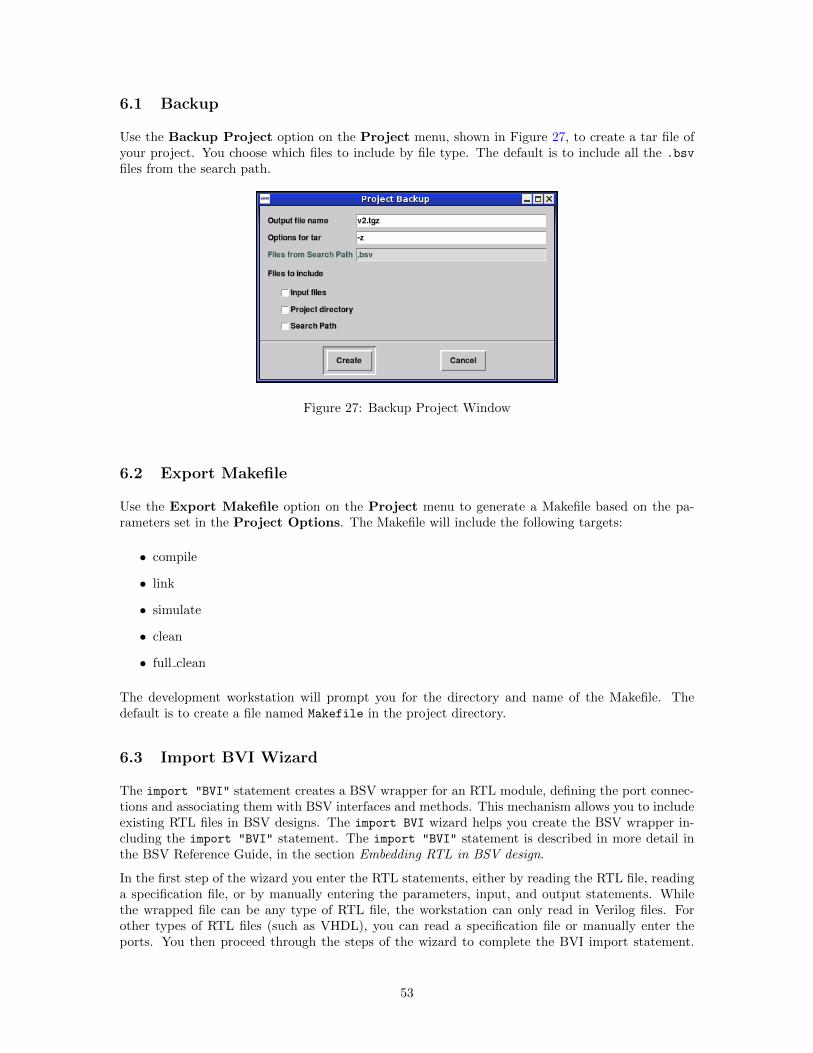
6.1 Backup
Use the Backup Project option on the Project menu, shown in Figure 27, to create a tar file ofyour project. You choose which files to include by file type. The default is to include all the .bsv
files from the search path.
Figure 27: Backup Project Window
6.2 Export Makefile
Use the Export Makefile option on the Project menu to generate a Makefile based on the pa-rameters set in the Project Options. The Makefile will include the following targets:
• compile
• link
• simulate
• clean
• full clean
The development workstation will prompt you for the directory and name of the Makefile. Thedefault is to create a file named Makefile in the project directory.
6.3 Import BVI Wizard
The import "BVI" statement creates a BSV wrapper for an RTL module, defining the port connec-tions and associating them with BSV interfaces and methods. This mechanism allows you to includeexisting RTL files in BSV designs. The import BVI wizard helps you create the BSV wrapper in-cluding the import "BVI" statement. The import "BVI" statement is described in more detail inthe BSV Reference Guide, in the section Embedding RTL in BSV design.
In the first step of the wizard you enter the RTL statements, either by reading the RTL file, readinga specification file, or by manually entering the parameters, input, and output statements. Whilethe wrapped file can be any type of RTL file, the workstation can only read in Verilog files. Forother types of RTL files (such as VHDL), you can read a specification file or manually enter theports. You then proceed through the steps of the wizard to complete the BVI import statement.
53
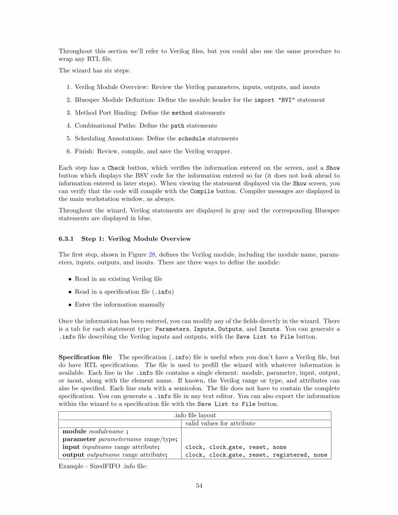
Throughout this section we’ll refer to Verilog files, but you could also use the same procedure towrap any RTL file.
The wizard has six steps:
1. Verilog Module Overview: Review the Verilog parameters, inputs, outputs, and inouts
2. Bluespec Module Definition: Define the module header for the import "BVI" statement
3. Method Port Binding: Define the method statements
4. Combinational Paths: Define the path statements
5. Scheduling Annotations: Define the schedule statements
6. Finish: Review, compile, and save the Verilog wrapper.
Each step has a Check button, which verifies the information entered on the screen, and a Show
button which displays the BSV code for the information entered so far (it does not look ahead toinformation entered in later steps). When viewing the statement displayed via the Show screen, youcan verify that the code will compile with the Compile button. Compiler messages are displayed inthe main workstation window, as always.
Throughout the wizard, Verilog statements are displayed in gray and the corresponding Bluespecstatements are displayed in blue.
6.3.1 Step 1: Verilog Module Overview
The first step, shown in Figure 28, defines the Verilog module, including the module name, param-eters, inputs, outputs, and inouts. There are three ways to define the module:
• Read in an existing Verilog file
• Read in a specification file (.info)
• Enter the information manually
Once the information has been entered, you can modify any of the fields directly in the wizard. Thereis a tab for each statement type: Parameters, Inputs, Outputs, and Inouts. You can generate a.info file describing the Verilog inputs and outputs, with the Save List to File button.
Specification file The specification (.info) file is useful when you don’t have a Verilog file, butdo have RTL specifications. The file is used to prefill the wizard with whatever information isavailable. Each line in the .info file contains a single element: module, parameter, input, output,or inout, along with the element name. If known, the Verilog range or type, and attributes canalso be specified. Each line ends with a semicolon. The file does not have to contain the completespecification. You can generate a .info file in any text editor. You can also export the informationwithin the wizard to a specification file with the Save List to File button.
.info file layoutvalid values for attribute
module modulename ;parameter parametername range/type;input inputname range attribute; clock, clock gate, reset, none
output outputname range attribute; clock, clock gate, reset, registered, none
Example - SizedFIFO .info file:
54
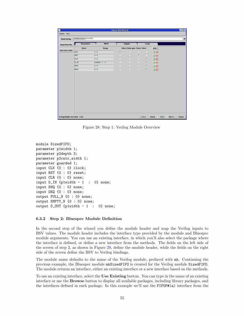
Figure 28: Step 1: Verilog Module Overview
module SizedFIFO;
parameter p1width 1;
parameter p2depth 3;
parameter p3cntr_width 1;
parameter guarded 1;
input CLK {0 : 0} clock;
input RST {0 : 0} reset;
input CLR {0 : 0} none;
input D_IN {p1width - 1 : 0} none;
input ENQ {0 : 0} none;
input DEQ {0 : 0} none;
output FULL_N {0 : 0} none;
output EMPTY_N {0 : 0} none;
output D_OUT {p1width - 1 : 0} none;
6.3.2 Step 2: Bluespec Module Definition
In the second step of the wizard you define the module header and map the Verilog inputs toBSV values. The module header includes the interface type provided by the module and Bluespecmodule arguments. You can use an existing interface, in which you’ll also select the package wherethe interface is defined, or define a new interface from the methods. The fields on the left side ofthe screen of step 2, as shown in Figure 29, define the module header, while the fields on the rightside of the screen define the BSV to Verilog bindings.
The module name defaults to the name of the Verilog module, prefaced with mk. Continuing theprevious example, the Bluespec module mkSizedFIFO is created for the Verilog module SizedFIFO.The module returns an interface, either an existing interface or a new interface based on the methods.
To use an existing interface, select the Use Existing button. You can type in the name of an existinginterface or use the Browse button to display all available packages, including library packages, andthe interfaces defined in each package. In this example we’ll use the FIFOF#(a) interface from the
55
Figure 29: Step 2: Bluespec Module Definition
FIFOF package. When using an existing interface, you must import the package which defines theinterface. In this example, the generated Bluespec wrapper will include the import statement forthe FIFOF package.
Select Define from Method to define a new interface. You’ll need to provide a name for the newinterface type. The rest of the interface will be defined in step 3 of the wizard. Instead of includingan import statement, an interface declaration will be added to the wrapper (.bsv) file generated.
All arguments and return values in the BSV wrapper must be in the Bits class or be of type Clock,Reset, Inout or a subinterface which meets these requirements. The Provisos for the FIFOF
example indicate that the data type of the FIFO, (a), along with the size of a, (sa), must both bein the Bits class. Finally, the module arguments are defined (depth and g in our example). Theinformation entered is enough to define the module header as follows:
import "BVI" SizedFIFO =
module mkSizedFIFO #(Integer depth, Bool g) (FIFOF#(a))
provisos(Bits#(a,sa));
The first tab (Parameters) on the right hand side of the screen connects the Verilog ports to theBSV parameters. Note that the BSV module’s parameters have no inherent relationship to theVerilog module’s parameters. These fields define the BSV expressions for the Verilog parameters,completing the parameter statements. The parameter statements for our example are:
parameter p1width = valueOf(sa);
parameter p2depth = depth;
parameter p3cntr_width = log2(depth+1);
parameter guarded = Bit#(1)’(pack(g));
56
The Input Clocks and Input Resets tabs define how the BSV clocks correspond to the Verilogclocks. The BSV clock defaults to clk Verilogclockname. The BSV reset defaults to rst Verilogresetname.Our example generates the following clock statements:
default_clock clk_CLK (CLK);
default_reset rst_RST_N (RST) clocked_by (clk_CLK);
You can view the complete wrapper generated at this point in the wizard using the Show button.Notice how the import FIFOF:: *: statement is included, since that is the package defining theFIFOF interface.
import FIFOF::*;
import "BVI" SizedFIFO =
module mkSizedFIFO #(Integer depth, Bool g) (FIFOF#(a))
provisos(Bits#(a,sa));
parameter p1width = valueOf(sa);
parameter p2depth = depth;
parameter p3cntr_width = log2(depth+1);
parameter guarded = Bit#(1)’(pack(g));
default_clock clk_CLK (CLK);
default_reset rst_RST_N (RST) clocked_by (clk_CLK);
endmodule
If you Compile the wrapper as defined at this point, you will see compiler errors, since the statementis not complete.
6.3.3 Step 3: Method Port Binding
Step 3 of the wizard builds the method statements connecting the methods in the Bluespec interfaceto the associated Verilog wires. How the default method statements are built depends on the typeof interface you are using:
• If you are using an existing interface, the method statements will be based on the methodsin the interface declaration. Check Use Existing and then select Build Skeleton to startdeclaring the method statements.
• If the interface type is Define from Method, the methods will be based on the Verilogstatements. Use Auto Create from Verilog to build the method statements.
Ports, methods, and subinterfaces are listed in the left box, as shown in Figure 30. To view thebindings, or connections between the BSV object and the Verilog wires, check the box next to theBSV object to display the bindings for that object.
The port bindings correspond to the port statements within the import "BVI" statement. Theport statement declares an input port which is not part of a method, along with the value to bepassed to the port. While parameters must be compile-time constants, ports can be dynamic.
There will only be interfaces when there are subinterfaces in the BSV interface declaration.
57
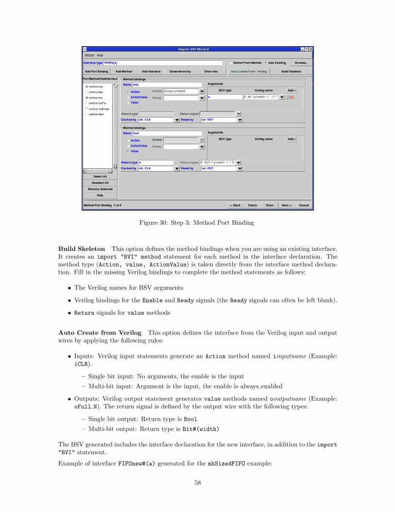
Figure 30: Step 3: Method Port Binding
Build Skeleton This option defines the method bindings when you are using an existing interface.It creates an import "BVI" method statement for each method in the interface declaration. Themethod type (Action, value, ActionValue) is taken directly from the interface method declara-tion. Fill in the missing Verilog bindings to complete the method statements as follows:
• The Verilog names for BSV arguments
• Verilog bindings for the Enable and Ready signals (the Ready signals can often be left blank).
• Return signals for value methods
Auto Create from Verilog This option defines the interface from the Verilog input and outputwires by applying the following rules:
• Inputs: Verilog input statements generate an Action method named iinputname (Example:iCLR).
– Single bit input: No arguments, the enable is the input
– Multi-bit input: Argument is the input, the enable is always enabled
• Outputs: Verilog output statement generates value methods named ooutputname (Example:oFull N). The return signal is defined by the output wire with the following types:
– Single bit output: Return type is Bool
– Multi-bit output: Return type is Bit#(width)
The BSV generated includes the interface declaration for the new interface, in addition to the import"BVI" statement.
Example of interface FIFOnew#(a) generated for the mkSizedFIFO example:
58
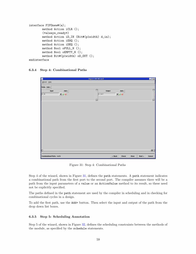
interface FIFOnew#(a);
method Action iCLR ();
(*always_ready*)
method Action iD_IN (Bit#(p1width) d_in);
method Action iENQ ();
method Action iDEQ ();
method Bool oFULL_N ();
method Bool oEMPTY_N ();
method Bit#(p1width) oD_OUT ();
endinterface
6.3.4 Step 4: Combinational Paths
Figure 31: Step 4: Combinational Paths
Step 4 of the wizard, shown in Figure 31, defines the path statements. A path statement indicatesa combinational path from the first port to the second port. The compiler assumes there will be apath from the input parameters of a value or an ActionValue method to its result, so these neednot be explicitly specified.
The paths defined in the path statement are used by the compiler in scheduling and in checking forcombinational cycles in a design.
To add the first path, use the Add+ button. Then select the input and output of the path from thedrop down list boxes.
6.3.5 Step 5: Scheduling Annotation
Step 5 of the wizard, shown in Figure 32, defines the scheduling constraints between the methods ofthe module, as specified by the schedule statements.
59
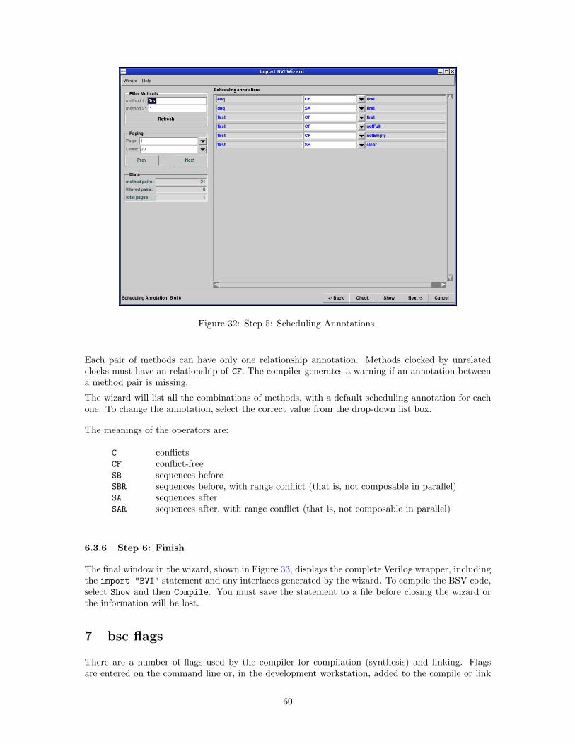
Figure 32: Step 5: Scheduling Annotations
Each pair of methods can have only one relationship annotation. Methods clocked by unrelatedclocks must have an relationship of CF. The compiler generates a warning if an annotation betweena method pair is missing.
The wizard will list all the combinations of methods, with a default scheduling annotation for eachone. To change the annotation, select the correct value from the drop-down list box.
The meanings of the operators are:
C conflictsCF conflict-freeSB sequences beforeSBR sequences before, with range conflict (that is, not composable in parallel)SA sequences afterSAR sequences after, with range conflict (that is, not composable in parallel)
6.3.6 Step 6: Finish
The final window in the wizard, shown in Figure 33, displays the complete Verilog wrapper, includingthe import "BVI" statement and any interfaces generated by the wizard. To compile the BSV code,select Show and then Compile. You must save the statement to a file before closing the wizard orthe information will be lost.
7 bsc flags
There are a number of flags used by the compiler for compilation (synthesis) and linking. Flagsare entered on the command line or, in the development workstation, added to the compile or link
60
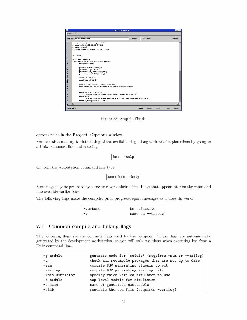
Figure 33: Step 6: Finish
options fields in the Project→Options window.
You can obtain an up-to-date listing of the available flags along with brief explanations by going toa Unix command line and entering:
bsc -help
Or from the workstation command line type:
exec bsc -help
Most flags may be preceded by a -no to reverse their effect. Flags that appear later on the commandline override earlier ones.
The following flags make the compiler print progress-report messages as it does its work:
-verbose be talkative
-v same as -verbose
7.1 Common compile and linking flags
The following flags are the common flags used by the compiler. These flags are automaticallygenerated by the development workstation, so you will only use them when executing bsc from aUnix command line.
-g module generate code for ‘module’ (requires -sim or -verilog)
-u check and recompile packages that are not up to date
-sim compile BSV generating Bluesim object
-verilog compile BSV generating Verilog file
-vsim simulator specify which Verilog simulator to use
-e module top-level module for simulation
-o name name of generated executable
-elab generate the .ba file (requires -verilog)
61
A BSV source file is compiled with a command like this:
bsc [flags] Foo.bsv
where Foo.bsv is the top file in the design.
If no flags are provided, the compile stops after the type checking phase. To compile through codegeneration, you must provide a flag indicating whether the target is Bluesim (-sim) or Verilog(-verilog).
For example, to compile to code generation for Bluesim:
bsc -sim Foo.bsv
or for Verilog:
bsc -verilog Foo.bsv
As discussed in Section 4.2.3, when compiling to code generation a module must be specified, usingeither the synthesize attribute in the BSV code, or the -g flag at compile time. When compilingfrom the workstation the Top Module field is automatically provided to the -g flag. From thecommand line, multiple modules can be specified for code generation at the same time.
For example:
bsc -sim -g mkFoo -g mkBaz Foo.bsv
Linking requires a second call to the compiler, as described in Section 3.2.4. When linking you mustspecify the top-level module with the -e flag. The name following the flag must be the name of aBSV module and only one module can be specified. You must also specify the back end with eitherthe -sim or -verilog flag.
For example, to link for Bluesim:
bsc -sim -e mkFoo
or for Verilog:
bsc -verilog -e mkFoo
The -vsim flag (along with the equivalent BSC VERILOG SIM environment variable) governs whichVerilog simulator is employed. The natively supported choices for -vsim are vcs, vcsi, ncverilog,modelsim, cver, iverilog, veriwell, and isim. If a simulator is not specified bsc will attempt todetect one of the above simulators and use it.
When using Bluespec Emulation App, SCE-MI, or any of the BlueTcl procedures, a .ba file isrequired. To generate this file when compiling add the -elab flag to the compile command.
7.2 Controlling default flag values
The environment variable BSC OPTIONS enables the user to set default flag values to be used eachtime the compiler is called. If set, the value of BSC OPTIONS is automatically prepended to thecompiler option values typed on the bsc command line. This avoids the need to set specified flagvalues each time the compiler is called.
For instance, in order to control the default value of the -p (path) option, the BSC OPTIONS envi-ronment variable could be set as follows:
62
# Bluespec Environment for csh/tcsh
setenv BSC_OPTIONS "-p .:./MyLib:+"
# Bluespec Environment for bash/ksh
export BSC_OPTIONS="-p .:./MyLib:+"
Once set, the BSV compiler would now search for packages in the ./MyLib directory before lookingin the default Prelude and Library areas. Note that since the compiler recognizes multiple usesof the same flag on the command line, the user can use the -p flag along with the BSC OPTIONS
environment variable to control the search path. For example, if in addition to the BSC OPTIONS setabove the user enters the following bsc command, :
bsc -verilog -p ./MyLib2:+ Foo.bsv
the compiler would now use the path
./MyLib2:.:./MyLib:+
which is a prepending of the -p command line value to the value set by the BSC OPTIONS environmentvariable.
7.3 Verilog back-end
The following additional flags are available when using the Verilog back end.
-remove-unused-modules remove unconnected modules from the Verilog
-v95 generate strict Verilog 95 code
-unspecified-to val remaining unspecified values are set to:
’X’, ’0’, ’1’, ’Z’, or ’A’
-remove-dollar remove dollar signs from Verilog identifiers
-Xv arg pass argument to the Verilog link process
-verilog-filter cmd invoke a command to post-process the generated Verilog
The -remove-unused-modules will remove from the generated Verilog any modules which are notconnected to an output. This has has the effect of removing redundant or unused modules, whichwould also be done by synthesis tools. This option should be used on modules undergoing synthesis,and not be used for testbench modules.
The -v95 flag restricts the Verilog output to pure Verilog-95. By default, the Verilog output usesfeatures which are not in the Verilog-95 standard. These features include passing module parametersby name and use of the $signed system task for formatting $display output. When the -v95 flagis turned on, uses of these features are removed, but comments are left in the Verilog indicating theparameter names or system tasks which were removed.
The -unspecified-to val flag defines the value which any remaining unspecified values should betied to. The valid set of values are: X, 0, 1, Z, or A, where the first four correspond to the Verilogvalue, and A corresponds to a vector of alternating ones and zeros. The default value is A. The choiceof value is used by both the Verilog and Bluesim back ends. However, since Bluesim is a two-valuesimulator, it does not support the values X and Z. For final synthesis runs, the use of X (or 0) isstrongly suggested to give the best synthesis results.
The -remove-dollar flag causes identifiers in Verilog output to substitute underscores instead ofdollar signs to separate instance names from port names. If this substitution causes a name collision,the underscore is suffixed with a number until a non-colliding name is found.
63
The -Xv flag passes the specified string argument to the Verilog link process. Only one argumentcan be passed with each -Xv flag. If you want to pass multiple arguments, then the flag must bespecified multiple times, once for each argument.
The -verilog-filter flag invokes a command to process the Verilog file generated by the compiler.The command can be a Unix command or script; it must take a single argument, the name of theVerilog file. The flag can be used multiple times; the filters are applied in the order they are givenon the command line.
7.4 Bluesim back-end
The following flags are available when using the Bluesim back end.
-parallel-sim-link jobs specify the # of simultaneous jobs when linking Bluesim
-systemc generate a SystemC model
During the Bluesim linking process, the compiler generates C++ source files (.cxx and .h files) andthen runs the C++ compiler on each one. By default, these compilations are performed serially. Insome cases, the C++ compiler may take time to compile a file. In that case, it would be helpful tocompile other files in parallel to reduce the total compilation time. The -parallel-sim-link flagdirects the process to proceed in parallel, up to jobs number of simultaneous compilations.
The default value of jobs is 1, in which case the compilation occurs in serial. Only values greaterthan 1 will allow parallel compilations.
When compilation occurs in parallel, it is controlled by a Makefile, described in Appendix A.6. Whenthe verbose (-v) flag is used to compile, you will now see the command for the make excecution.The commands for compiling each object will still be shown as well. Since the compilations arehappening in parallel, the messages will be interspersed with each other and will not show up inserial order (Section 8.2.1).
The -systemc flag instructs the linking stage to generate a SystemC model instead of a Bluesimexecutable (Section 4.3.2). When using this flag, the object files created to describe the design inC++ are not linked into a Bluesim exectuable. Instead, some additional files are created to providea SystemC interface to the compiled model. These additional SystemC files use the name of thetop-level module extended with a systemc suffix.
7.5 SceMi back-end
The following flags are available when building a model using the Sce-Mi link. See the EmulationApp User Manual for more information about using SceMi with the Bluespec compiler.
-scemi build a model using Sce-Mi link
-scemiTB build a testbench model using Sce-Mi link
-scemi-classic build a model or a testbench model using the
Classic Sce-Mi infrastructure
When using SceMi, the scemilink infrastructure tool must be run between the first and second bsccompilation stages. The linking stage is then run with the addition of the -scemi flag. This flaginstructs the linking stage to integrate the output of scemilink into the generated simulation model.
A SceMi environment includes a host testbench, which can be written in C/C++ or BSV. The-scemiTb flag is required when using a BSV testbench. The flag instructs the linking stage to linkin the necessary routines for a BSV testbench to communicate with the SceMi infrastructure.
Bluespec supports two different SceMi infrastructures: BlueNoC and Classic. Classic is necessaryfor Virtex 5 boards; all other supported boards use BlueNoC. The default setting is BlueNoC. If youare compiling for a Vertex 5 board the -scemi-classic flag must be provided.
64
7.6 Resource scheduling (all back ends)
The following flags are available to direct resource scheduling:
-resource-off fail on insufficient resources
-resource-simple reschedule on insufficient resources
Resource scheduling for a particular interface method involves finding all rules that call that method.A single method name can refer to multiple ports in the hardware — for example, a double-portedRAM can have two read ports, but a design in BSV can use the name read and it will rely on thecompiler to determine which port is being used. If the number of rules that use read is two or less,then there is no problem; each rule is connected to its own port and there is never any contention.If the number of rules vying for a method is more than the number of copies of that method, thena problem exists.
If -resource-off is specified, the compiler will give up and tell the user that resource schedulingis not possible. This is the default behavior. The straightforward way to proceed is by addinglogic that explicitly arbitrates between the competing rules (choosing the more important one to firedepending on the situation).
The alternative way to resolve a resource conflict is to block competing rules until the number ofrules vying for a method is less than the number of available ports for that method. This behaviorcan be turned on with the -resource-simple flag. The compiler selects rules to block from thecompeting rules arbitrarily (and may change its selection when different compilation flags or compilerversions are used), so this flag is not recommended for a completed design, but automatic resourcearbitration can be useful when experimenting.
7.7 Setting the path
-i dir override $BLUESPECDIR
-p path directory path (‘:’ sep.) for source and intermediate
files
-bdir dir output directory for .bo and .ba files
-simdir dir output directory for Bluesim intermediate files
-vdir dir output directory for .v files
-vsearch path search path (‘:’ sep.) for Verilog files
-info-dir dir output directory for informational files
-I path include path for compiling foreign C/C++ source
-L path library path for linking foreign C/C++ objects
-l library library to use when linking foreign C/C++ objects
-fdir dir working directory for relative file paths during elaboration
There are default locations where the compiler looks for source and and intermediate files. Theflags -i and -p are available to override the default locations or to specify additional directories tosearch in. See Section 4.2.4 for more information. The -i flag overrides the environment variableBLUESPECDIR, which is used in the default value for the directory path of the -p flag. The -p
flag takes a path argument, which is a colon-delimited list of directories. This path is used tofind Bluespec source and intermediate files imported by the package being compiled (including thestandard prelude, and files included by the BSV preprocessor). The path can contain the character%, representing the BLUESPECDIR directory, as well as +, representing the current path. The defaultpath is:
.:%/Prelude:%/Libraries
65
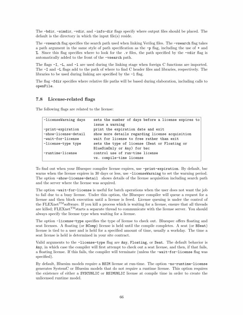
The -bdir, -simdir, -vdir, and -info-dir flags specify where output files should be placed. Thedefault is the directory in which the input file(s) reside.
The -vsearch flag specifies the search path used when linking Verilog files. The -vsearch flag takesa path argument in the same style of path specification as the -p flag, including the use of + and%. Since this flag specifies where to look for the .v files, the path specified by the -vdir flag isautomatically added to the front of the -vsearch path.
The flags -I, -L, and -l are used during the linking stage when foreign C functions are imported.The -I and -L flags add to the path of where to find C header files and libraries, respectively. Thelibraries to be used during linking are specified by the -l flag.
The flag -fdir specifies where relative file paths will be based during elaboration, including calls toopenFile.
7.8 License-related flags
The following flags are related to the license:
-licenseWarning days sets the number of days before a license expires to
issue a warning
-print-expiration print the expiration date and exit
-show-license-detail show more details regarding license acquisition
-wait-for-license wait for license to free rather than exit
-license-type type sets the type of license (Seat or Floating or
BlueSimOnly or Any) for bsc
-runtime-license control use of run-time license
vs. compile-time license
To find out when your Bluespec compiler license expires, use -print-expiration. By default, bscwarns when the license expires in 30 days or less, use -licenseWarning to set the warning period.The option -show-license-detail shows details of the license acquisition including search pathand the server where the license was acquired.
The option -wait-for-license is useful for batch operations when the user does not want the jobto fail due to a busy license. Under this option, the Bluespec compiler will queue a request for alicense and then block execution until a license is freed. License queuing is under the control ofthe FLEXnetTMsoftware. If you kill a process which is waiting for a license, ensure that all threadsare killed; FLEXnetTMstarts a separate thread to communicate with the license server. You shouldalways specify the license type when waiting for a license.
The option -license-type specifies the type of license to check out. Bluespec offers floating andseat licenses. A floating (or BComp) license is held until the compile completes. A seat (or BSeat)license is tied to a user and is held for a specified amount of time, usually a workday. The time aseat license is held is determined in your site contract.
Valid arguments to the -license-type flag are Any, Floating, or Seat. The default behavior isAny, in which case the compiler will first attempt to check out a seat license, and then, if that fails,a floating license. If this fails, the compiler will terminate (unless the -wait-for-license flag wasspecified).
By default, Bluesim models require a BSIM license at run-time. The option -no-runtime-license
generates SystemC or Bluesim models that do not require a runtime license. This option requiresthe existence of either a SYSCUNLIC or BSIMUNLIC license at compile time in order to create theunlicensed runtime model.
66
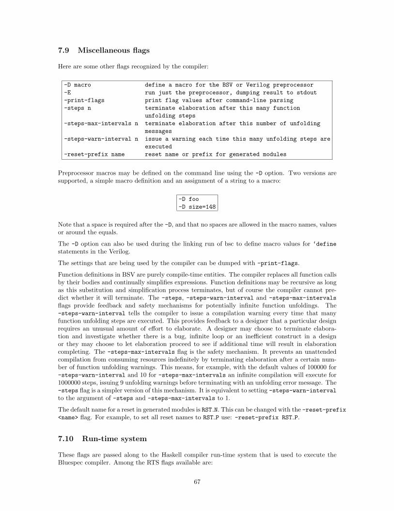
7.9 Miscellaneous flags
Here are some other flags recognized by the compiler:
-D macro define a macro for the BSV or Verilog preprocessor
-E run just the preprocessor, dumping result to stdout
-print-flags print flag values after command-line parsing
-steps n terminate elaboration after this many function
unfolding steps
-steps-max-intervals n terminate elaboration after this number of unfolding
messages
-steps-warn-interval n issue a warning each time this many unfolding steps are
executed
-reset-prefix name reset name or prefix for generated modules
Preprocessor macros may be defined on the command line using the -D option. Two versions aresupported, a simple macro definition and an assignment of a string to a macro:
-D foo
-D size=148
Note that a space is required after the -D, and that no spaces are allowed in the macro names, valuesor around the equals.
The -D option can also be used during the linking run of bsc to define macro values for ‘define
statements in the Verilog.
The settings that are being used by the compiler can be dumped with -print-flags.
Function definitions in BSV are purely compile-time entities. The compiler replaces all function callsby their bodies and continually simplifies expressions. Function definitions may be recursive as longas this substitution and simplification process terminates, but of course the compiler cannot pre-dict whether it will terminate. The -steps, -steps-warn-interval and -steps-max-intervals
flags provide feedback and safety mechanisms for potentially infinite function unfoldings. The-steps-warn-interval tells the compiler to issue a compilation warning every time that manyfunction unfolding steps are executed. This provides feedback to a designer that a particular designrequires an unusual amount of effort to elaborate. A designer may choose to terminate elabora-tion and investigate whether there is a bug, infinite loop or an inefficient construct in a designor they may choose to let elaboration proceed to see if additional time will result in elaborationcompleting. The -steps-max-intervals flag is the safety mechanism. It prevents an unattendedcompilation from consuming resources indefinitely by terminating elaboration after a certain num-ber of function unfolding warnings. This means, for example, with the default values of 100000 for-steps-warn-interval and 10 for -steps-max-intervals an infinite compilation will execute for1000000 steps, issuing 9 unfolding warnings before terminating with an unfolding error message. The-steps flag is a simpler version of this mechanism. It is equivalent to setting -steps-warn-interval
to the argument of -steps and -steps-max-intervals to 1.
The default name for a reset in generated modules is RST N. This can be changed with the -reset-prefix<name> flag. For example, to set all reset names to RST P use: -reset-prefix RST P.
7.10 Run-time system
These flags are passed along to the Haskell compiler run-time system that is used to execute theBluespec compiler. Among the RTS flags available are:
67
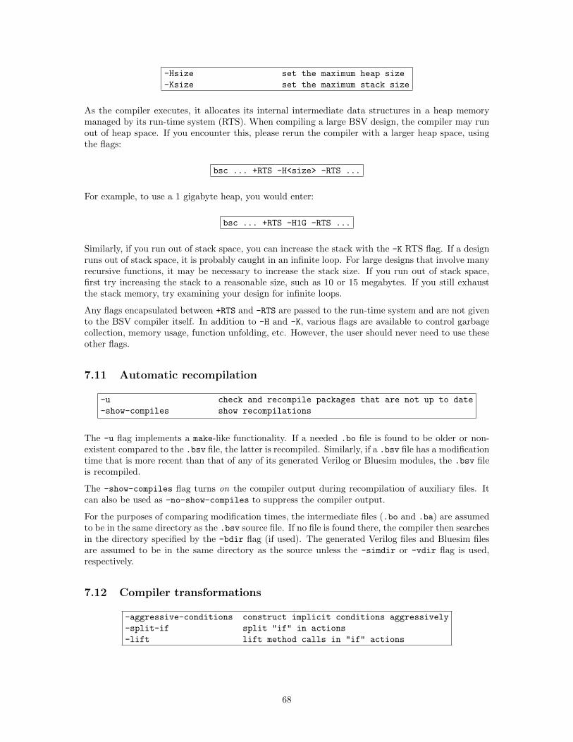
-Hsize set the maximum heap size
-Ksize set the maximum stack size
As the compiler executes, it allocates its internal intermediate data structures in a heap memorymanaged by its run-time system (RTS). When compiling a large BSV design, the compiler may runout of heap space. If you encounter this, please rerun the compiler with a larger heap space, usingthe flags:
bsc ... +RTS -H<size> -RTS ...
For example, to use a 1 gigabyte heap, you would enter:
bsc ... +RTS -H1G -RTS ...
Similarly, if you run out of stack space, you can increase the stack with the -K RTS flag. If a designruns out of stack space, it is probably caught in an infinite loop. For large designs that involve manyrecursive functions, it may be necessary to increase the stack size. If you run out of stack space,first try increasing the stack to a reasonable size, such as 10 or 15 megabytes. If you still exhaustthe stack memory, try examining your design for infinite loops.
Any flags encapsulated between +RTS and -RTS are passed to the run-time system and are not givento the BSV compiler itself. In addition to -H and -K, various flags are available to control garbagecollection, memory usage, function unfolding, etc. However, the user should never need to use theseother flags.
7.11 Automatic recompilation
-u check and recompile packages that are not up to date
-show-compiles show recompilations
The -u flag implements a make-like functionality. If a needed .bo file is found to be older or non-existent compared to the .bsv file, the latter is recompiled. Similarly, if a .bsv file has a modificationtime that is more recent than that of any of its generated Verilog or Bluesim modules, the .bsv fileis recompiled.
The -show-compiles flag turns on the compiler output during recompilation of auxiliary files. Itcan also be used as -no-show-compiles to suppress the compiler output.
For the purposes of comparing modification times, the intermediate files (.bo and .ba) are assumedto be in the same directory as the .bsv source file. If no file is found there, the compiler then searchesin the directory specified by the -bdir flag (if used). The generated Verilog files and Bluesim filesare assumed to be in the same directory as the source unless the -simdir or -vdir flag is used,respectively.
7.12 Compiler transformations
-aggressive-conditions construct implicit conditions aggressively
-split-if split "if" in actions
-lift lift method calls in "if" actions
68
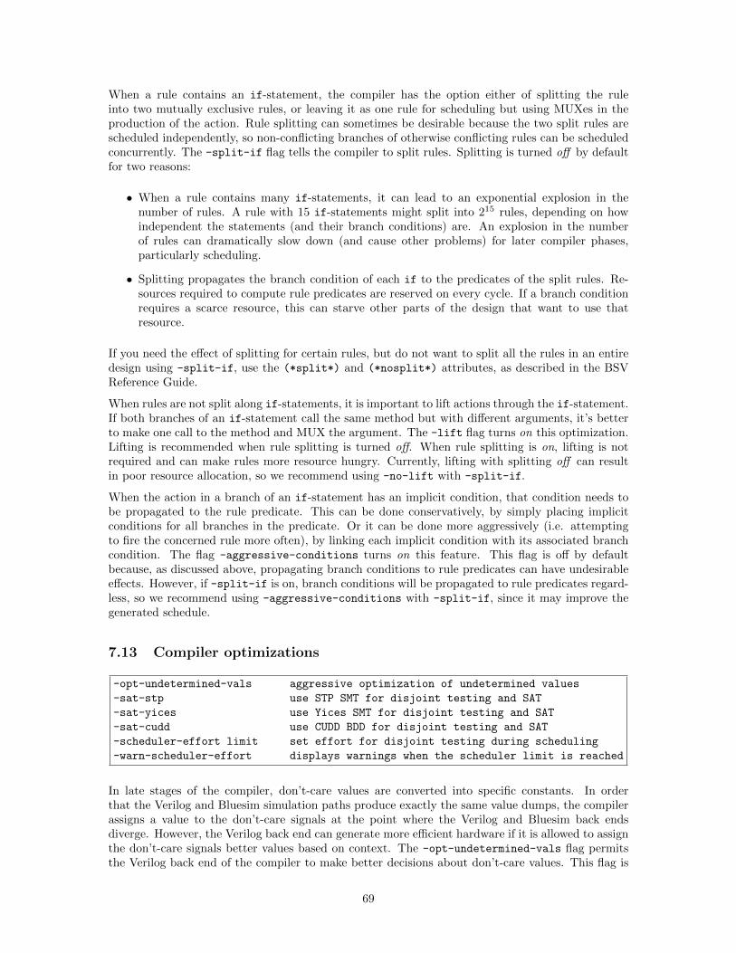
When a rule contains an if-statement, the compiler has the option either of splitting the ruleinto two mutually exclusive rules, or leaving it as one rule for scheduling but using MUXes in theproduction of the action. Rule splitting can sometimes be desirable because the two split rules arescheduled independently, so non-conflicting branches of otherwise conflicting rules can be scheduledconcurrently. The -split-if flag tells the compiler to split rules. Splitting is turned off by defaultfor two reasons:
• When a rule contains many if-statements, it can lead to an exponential explosion in thenumber of rules. A rule with 15 if-statements might split into 215 rules, depending on howindependent the statements (and their branch conditions) are. An explosion in the numberof rules can dramatically slow down (and cause other problems) for later compiler phases,particularly scheduling.
• Splitting propagates the branch condition of each if to the predicates of the split rules. Re-sources required to compute rule predicates are reserved on every cycle. If a branch conditionrequires a scarce resource, this can starve other parts of the design that want to use thatresource.
If you need the effect of splitting for certain rules, but do not want to split all the rules in an entiredesign using -split-if, use the (*split*) and (*nosplit*) attributes, as described in the BSVReference Guide.
When rules are not split along if-statements, it is important to lift actions through the if-statement.If both branches of an if-statement call the same method but with different arguments, it’s betterto make one call to the method and MUX the argument. The -lift flag turns on this optimization.Lifting is recommended when rule splitting is turned off. When rule splitting is on, lifting is notrequired and can make rules more resource hungry. Currently, lifting with splitting off can resultin poor resource allocation, so we recommend using -no-lift with -split-if.
When the action in a branch of an if-statement has an implicit condition, that condition needs tobe propagated to the rule predicate. This can be done conservatively, by simply placing implicitconditions for all branches in the predicate. Or it can be done more aggressively (i.e. attemptingto fire the concerned rule more often), by linking each implicit condition with its associated branchcondition. The flag -aggressive-conditions turns on this feature. This flag is off by defaultbecause, as discussed above, propagating branch conditions to rule predicates can have undesirableeffects. However, if -split-if is on, branch conditions will be propagated to rule predicates regard-less, so we recommend using -aggressive-conditions with -split-if, since it may improve thegenerated schedule.
7.13 Compiler optimizations
-opt-undetermined-vals aggressive optimization of undetermined values
-sat-stp use STP SMT for disjoint testing and SAT
-sat-yices use Yices SMT for disjoint testing and SAT
-sat-cudd use CUDD BDD for disjoint testing and SAT
-scheduler-effort limit set effort for disjoint testing during scheduling
-warn-scheduler-effort displays warnings when the scheduler limit is reached
In late stages of the compiler, don’t-care values are converted into specific constants. In orderthat the Verilog and Bluesim simulation paths produce exactly the same value dumps, the compilerassigns a value to the don’t-care signals at the point where the Verilog and Bluesim back endsdiverge. However, the Verilog back end can generate more efficient hardware if it is allowed to assignthe don’t-care signals better values based on context. The -opt-undetermined-vals flag permitsthe Verilog back end of the compiler to make better decisions about don’t-care values. This flag is
69
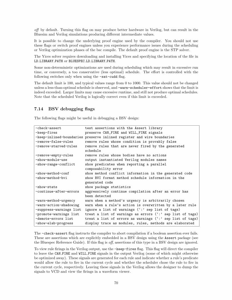
off by default. Turning this flag on may produce better hardware in Verilog, but can result in theBluesim and Verilog simulations producing different intermediate values.
It is possible to change the underlying proof engine used by the compiler. You should not usethese flags or switch proof engines unless you experience performance issues during the schedulingor Verilog optimization phases of the bsc compile. The default proof engine is the STP solver.
The Yices solver requires downloading and installing Yices and specifying the location of the file inLD LIBRARY PATH or BLUESPEC LD LIBRARY PATH.
Some non-deterministic optimizations are used during scheduling which may result in excessive runtime, or conversely, a too conservative (less optimal) schedule. The effort is controlled with thefollowing switches only when using the -sat-cudd flag.
The default limit is 100, and typical values range from 0 to 1000. This value should not be changedunless a less-than-optimal schedule is observed, and -warn-scheduler-effort shows that the limit isindeed exceeded. Larger limits may cause excessive runtime, and still not produce optimal schedules.Note that the scheduled Verilog is logically correct even if this limit is exceeded.
7.14 BSV debugging flags
The following flags might be useful in debugging a BSV design:
-check-assert test assertions with the Assert library
-keep-fires preserve CAN_FIRE and WILL_FIRE signals
-keep-inlined-boundaries preserve inlined register and wire boundaries
-remove-false-rules remove rules whose condition is provably false
-remove-starved-rules remove rules that are never fired by the generated
schedule
-remove-empty-rules remove rules whose bodies have no actions
-show-module-use output instantiated Verilog modules names
-show-range-conflict show predicates when reporting a parallel
composability error
-show-method-conf show method conflict information in the generated code
-show-method-bvi show BVI format method schedule information in the
generated code
-show-stats show package statistics
-continue-after-errors aggressively continue compilation after an error has
been detected
-warn-method-urgency warn when a method’s urgency is arbitrarily chosen
-warn-action-shadowing warn when a rule’s action is overwritten by a later rule
-suppress-warnings list ignore a list of warnings (‘:’ sep list of tags)
-promote-warnings list treat a list of warnings as errors (‘:’ sep list of tags)
-demote-errors list treat a list of errors as warnings (‘:’ sep list of tags)
-show-elab-progress display trace as modules, rules, methods are elaborated
The -check-assert flag instructs the compiler to abort compilation if a boolean assertion ever fails.These are assertions which are explicitly embedded in a BSV design using the Assert package (seethe Bluespec Reference Guide). If this flag is off, assertions of this type in a BSV design are ignored.
To view rule firings in the Verilog output, use the -keep-fires flag. This flag will direct the compilerto leave the CAN FIRE and WILL FIRE signals in the output Verilog (some of which might otherwisebe optimized away). These signals are generated for each rule and indicate whether a rule’s predicatewould allow the rule to fire in the current cycle and whether the scheduler chose the rule to fire inthe current cycle, respectively. Leaving these signals in the Verilog allows the designer to dump thesignals to VCD and view the firings in a waveform viewer.
70
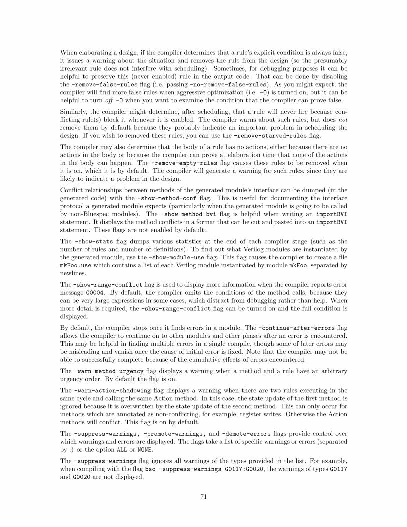
When elaborating a design, if the compiler determines that a rule’s explicit condition is always false,it issues a warning about the situation and removes the rule from the design (so the presumablyirrelevant rule does not interfere with scheduling). Sometimes, for debugging purposes it can behelpful to preserve this (never enabled) rule in the output code. That can be done by disablingthe -remove-false-rules flag (i.e. passing -no-remove-false-rules). As you might expect, thecompiler will find more false rules when aggressive optimization (i.e. -O) is turned on, but it can behelpful to turn off -O when you want to examine the condition that the compiler can prove false.
Similarly, the compiler might determine, after scheduling, that a rule will never fire because con-flicting rule(s) block it whenever it is enabled. The compiler warns about such rules, but does notremove them by default because they probably indicate an important problem in scheduling thedesign. If you wish to removed these rules, you can use the -remove-starved-rules flag.
The compiler may also determine that the body of a rule has no actions, either because there are noactions in the body or because the compiler can prove at elaboration time that none of the actionsin the body can happen. The -remove-empty-rules flag causes these rules to be removed whenit is on, which it is by default. The compiler will generate a warning for such rules, since they arelikely to indicate a problem in the design.
Conflict relationships between methods of the generated module’s interface can be dumped (in thegenerated code) with the -show-method-conf flag. This is useful for documenting the interfaceprotocol a generated module expects (particularly when the generated module is going to be calledby non-Bluespec modules). The -show-method-bvi flag is helpful when writing an importBVI
statement. It displays the method conflicts in a format that can be cut and pasted into an importBVI
statement. These flags are not enabled by default.
The -show-stats flag dumps various statistics at the end of each compiler stage (such as thenumber of rules and number of definitions). To find out what Verilog modules are instantiated bythe generated module, use the -show-module-use flag. This flag causes the compiler to create a filemkFoo.use which contains a list of each Verilog module instantiated by module mkFoo, separated bynewlines.
The -show-range-conflict flag is used to display more information when the compiler reports errormessage G0004. By default, the compiler omits the conditions of the method calls, because theycan be very large expressions in some cases, which distract from debugging rather than help. Whenmore detail is required, the -show-range-conflict flag can be turned on and the full condition isdisplayed.
By default, the compiler stops once it finds errors in a module. The -continue-after-errors flagallows the compiler to continue on to other modules and other phases after an error is encountered.This may be helpful in finding multiple errors in a single compile, though some of later errors maybe misleading and vanish once the cause of initial error is fixed. Note that the compiler may not beable to successfully complete because of the cumulative effects of errors encountered.
The -warn-method-urgency flag displays a warning when a method and a rule have an arbitraryurgency order. By default the flag is on.
The -warn-action-shadowing flag displays a warning when there are two rules executing in thesame cycle and calling the same Action method. In this case, the state update of the first method isignored because it is overwritten by the state update of the second method. This can only occur formethods which are annotated as non-conflicting, for example, register writes. Otherwise the Actionmethods will conflict. This flag is on by default.
The -suppress-warnings, -promote-warnings, and -demote-errors flags provide control overwhich warnings and errors are displayed. The flags take a list of specific warnings or errors (separatedby :) or the option ALL or NONE.
The -suppress-warnings flag ignores all warnings of the types provided in the list. For example,when compiling with the flag bsc -suppress-warnings G0117:G0020, the warnings of types G0117and G0020 are not displayed.
71
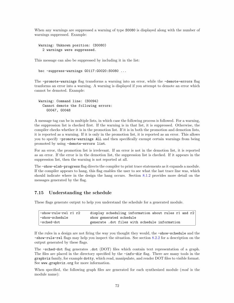
When any warnings are suppressed a warning of type S0080 is displayed along with the number ofwarnings suppressed. Example:
Warning: Unknown position: (S0080)
2 warnings were suppressed.
This message can also be suppressed by including it in the list:
bsc -suppress-warnings G0117:G0020:S0080 ...
The -promote-warnings flag transforms a warning into an error, while the -demote-errors flagtranforms an error into a warning. A warning is displayed if you attempt to demote an error whichcannot be demoted. Example:
Warning: Command line: (S0094)
Cannot demote the following errors:
G0047, G0048
A message tag can be in multiple lists, in which case the following process is followed. For a warning,the suppression list is checked first. If the warning is in that list, it is suppressed. Otherwise, thecompiler checks whether it is in the promotion list. If it is in both the promotion and demotion lists,it is reported as a warning. If it is only in the promotion list, it is reported as an error. This allowsyou to specify -promote-warnings ALL and then specifically exempt certain warnings from beingpromoted by using -demote-errors list.
For an error, the promotion list is irrelevant. If an error is not in the demotion list, it is reportedas an error. If the error is in the demotion list, the suppression list is checked. If it appears in thesuppression list, then the warning is not reported at all.
The -show-elab-progress flag directs the compiler to print trace statements as it expands a module.If the compiler appears to hang, this flag enables the user to see what the last trace line was, whichshould indicate where in the design the hang occurs. Section 8.1.2 provides more detail on themessages generated by the flag.
7.15 Understanding the schedule
These flags generate output to help you understand the schedule for a generated module.
-show-rule-rel r1 r2 display scheduling information about rules r1 and r2
-show-schedule show generated schedule
-sched-dot generate .dot files with schedule information
If the rules in a design are not firing the way you thought they would, the -show-schedule and the-show-rule-rel flags may help you inspect the situation. See section 8.2.2 for a description on theoutput generated by these flags.
The -sched-dot flag generates .dot (DOT) files which contain text representation of a graph.The files are placed in the directory specified by the -info-dir flag. There are many tools in thegraphviz family, for example dotty, which read, manipulate, and render DOT files to visible format.See www.graphviz.org for more information.
When specified, the following graph files are generated for each synthesized module (mod is themodule name):
72
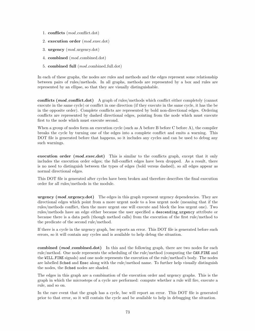
1. conflicts (mod conflict.dot)
2. execution order (mod exec.dot)
3. urgency (mod urgency.dot)
4. combined (mod combined.dot)
5. combined full (mod combined full.dot)
In each of these graphs, the nodes are rules and methods and the edges represent some relationshipbetween pairs of rules/methods. In all graphs, methods are represented by a box and rules arerepresented by an ellipse, so that they are visually distinguishable.
conflicts (mod conflict.dot) A graph of rules/methods which conflict either completely (cannotexecute in the same cycle) or conflict in one direction (if they execute in the same cycle, it has the bein the opposite order). Complete conflicts are represented by bold non-directional edges. Orderingconflicts are represented by dashed directional edges, pointing from the node which must executefirst to the node which must execute second.
When a group of nodes form an execution cycle (such as A before B before C before A), the compilerbreaks the cycle by turning one of the edges into a complete conflict and emits a warning. ThisDOT file is generated before that happens, so it includes any cycles and can be used to debug anysuch warnings.
execution order (mod exec.dot) This is similar to the conflicts graph, except that it onlyincludes the execution order edges; the full-conflict edges have been dropped. As a result, thereis no need to distinguish between the types of edges (bold versus dashed), so all edges appear asnormal directional edges.
This DOT file is generated after cycles have been broken and therefore describes the final executionorder for all rules/methods in the module.
urgency (mod urgency.dot) The edges in this graph represent urgency dependencies. They aredirectional edges which point from a more urgent node to a less urgent node (meaning that if therules/methods conflict, then the more urgent one will execute and block the less urgent one). Tworules/methods have an edge either because the user specified a descending urgency attribute orbecause there is a data path (though method calls) from the execution of the first rule/method tothe predicate of the second rule/method.
If there is a cycle in the urgency graph, bsc reports an error. This DOT file is generated before sucherrors, so it will contain any cycles and is available to help debug the situation.
combined (mod combined.dot) In this and the following graph, there are two nodes for eachrule/method. One node represents the scheduling of the rule/method (computing the CAN FIRE andthe WILL FIRE signals) and one node represents the execution of the rule/method’s body. The nodesare labelled Sched and Exec along with the rule/method name. To further help visually distinguishthe nodes, the Sched nodes are shaded.
The edges in this graph are a combination of the execution order and urgency graphs. This is thegraph in which the microsteps of a cycle are performed: compute whether a rule will fire, execute arule, and so on.
In the rare event that the graph has a cycle, bsc will report an error. This DOT file is generatedprior to that error, so it will contain the cycle and be available to help in debugging the situation.
73
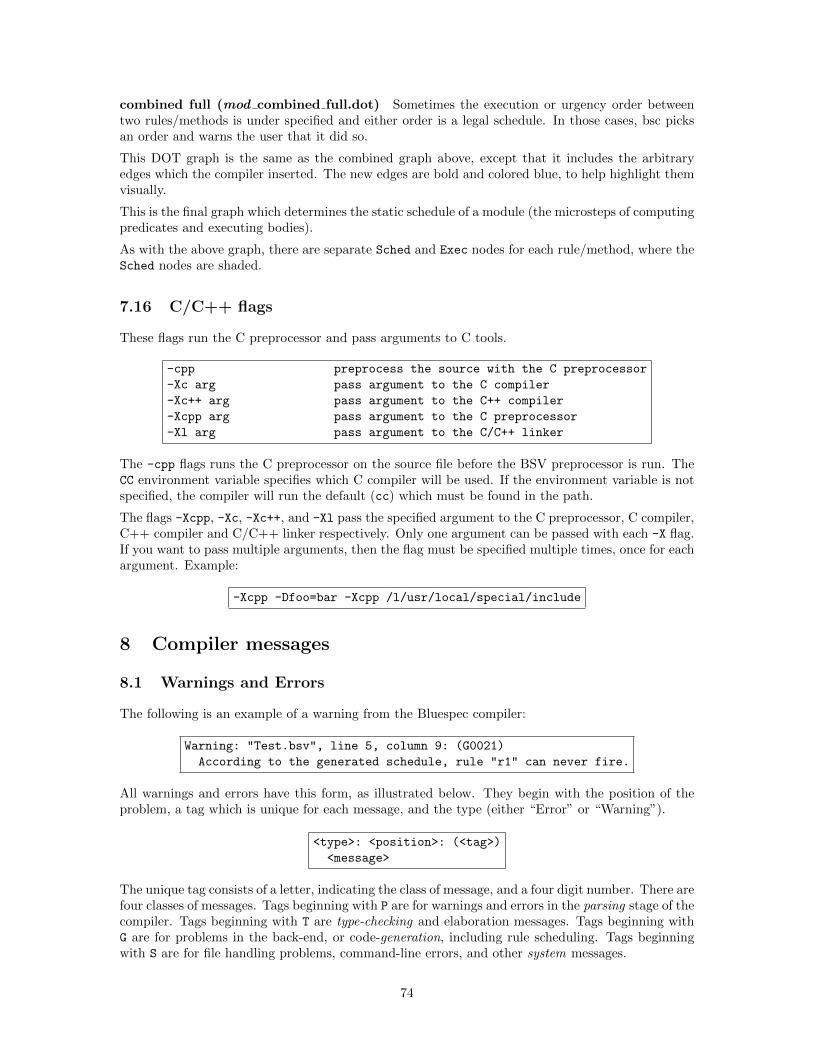
combined full (mod combined full.dot) Sometimes the execution or urgency order betweentwo rules/methods is under specified and either order is a legal schedule. In those cases, bsc picksan order and warns the user that it did so.
This DOT graph is the same as the combined graph above, except that it includes the arbitraryedges which the compiler inserted. The new edges are bold and colored blue, to help highlight themvisually.
This is the final graph which determines the static schedule of a module (the microsteps of computingpredicates and executing bodies).
As with the above graph, there are separate Sched and Exec nodes for each rule/method, where theSched nodes are shaded.
7.16 C/C++ flags
These flags run the C preprocessor and pass arguments to C tools.
-cpp preprocess the source with the C preprocessor
-Xc arg pass argument to the C compiler
-Xc++ arg pass argument to the C++ compiler
-Xcpp arg pass argument to the C preprocessor
-Xl arg pass argument to the C/C++ linker
The -cpp flags runs the C preprocessor on the source file before the BSV preprocessor is run. TheCC environment variable specifies which C compiler will be used. If the environment variable is notspecified, the compiler will run the default (cc) which must be found in the path.
The flags -Xcpp, -Xc, -Xc++, and -Xl pass the specified argument to the C preprocessor, C compiler,C++ compiler and C/C++ linker respectively. Only one argument can be passed with each -X flag.If you want to pass multiple arguments, then the flag must be specified multiple times, once for eachargument. Example:
-Xcpp -Dfoo=bar -Xcpp /l/usr/local/special/include
8 Compiler messages
8.1 Warnings and Errors
The following is an example of a warning from the Bluespec compiler:
Warning: "Test.bsv", line 5, column 9: (G0021)
According to the generated schedule, rule "r1" can never fire.
All warnings and errors have this form, as illustrated below. They begin with the position of theproblem, a tag which is unique for each message, and the type (either “Error” or “Warning”).
<type>: <position>: (<tag>)
<message>
The unique tag consists of a letter, indicating the class of message, and a four digit number. There arefour classes of messages. Tags beginning with P are for warnings and errors in the parsing stage of thecompiler. Tags beginning with T are type-checking and elaboration messages. Tags beginning withG are for problems in the back-end, or code-generation, including rule scheduling. Tags beginningwith S are for file handling problems, command-line errors, and other system messages.
74
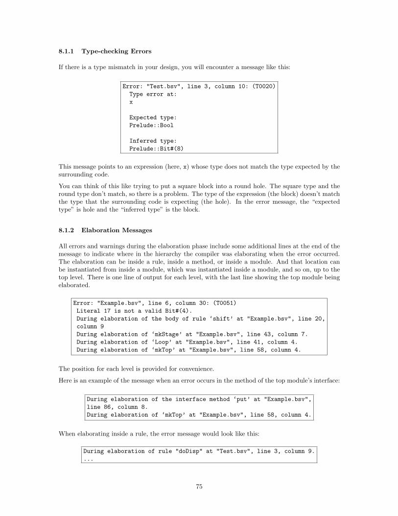
8.1.1 Type-checking Errors
If there is a type mismatch in your design, you will encounter a message like this:
Error: "Test.bsv", line 3, column 10: (T0020)
Type error at:
x
Expected type:
Prelude::Bool
Inferred type:
Prelude::Bit#(8)
This message points to an expression (here, x) whose type does not match the type expected by thesurrounding code.
You can think of this like trying to put a square block into a round hole. The square type and theround type don’t match, so there is a problem. The type of the expression (the block) doesn’t matchthe type that the surrounding code is expecting (the hole). In the error message, the “expectedtype” is hole and the “inferred type” is the block.
8.1.2 Elaboration Messages
All errors and warnings during the elaboration phase include some additional lines at the end of themessage to indicate where in the hierarchy the compiler was elaborating when the error occurred.The elaboration can be inside a rule, inside a method, or inside a module. And that location canbe instantiated from inside a module, which was instantiated inside a module, and so on, up to thetop level. There is one line of output for each level, with the last line showing the top module beingelaborated.
Error: "Example.bsv", line 6, column 30: (T0051)
Literal 17 is not a valid Bit#(4).
During elaboration of the body of rule ‘shift’ at "Example.bsv", line 20,
column 9
During elaboration of ‘mkStage’ at "Example.bsv", line 43, column 7.
During elaboration of ‘Loop’ at "Example.bsv", line 41, column 4.
During elaboration of ‘mkTop’ at "Example.bsv", line 58, column 4.
The position for each level is provided for convenience.
Here is an example of the message when an error occurs in the method of the top module’s interface:
During elaboration of the interface method ‘put’ at "Example.bsv",
line 86, column 8.
During elaboration of ‘mkTop’ at "Example.bsv", line 58, column 4.
When elaborating inside a rule, the error message would look like this:
During elaboration of rule "doDisp" at "Test.bsv", line 3, column 9.
...
75
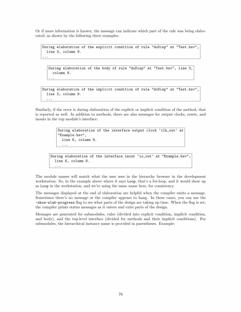
Or if more information is known, the message can indicate which part of the rule was being elabo-rated, as shown by the following three examples:
During elaboration of the explicit condition of rule "doDisp" at "Test.bsv",
line 3, column 9.
...
During elaboration of the body of rule "doDisp" at "Test.bsv", line 3,
column 9.
...
During elaboration of the implicit condition of rule "doDisp" at "Test.bsv",
line 3, column 9.
...
Similarly, if the error is during elaboration of the explicit or implicit condition of the method, thatis reported as well. In addition to methods, there are also messages for output clocks, resets, andinouts in the top module’s interface:
During elaboration of the interface output clock ‘clk_out’ at
"Example.bsv",
line 6, column 8.
...
During elaboration of the interface inout ‘io_out’ at "Example.bsv",
line 6, column 8.
...
The module names will match what the user sees in the hierarchy browser in the developmentworkstation. So, in the example above where it says Loop, that’s a for-loop, and it would show upas Loop in the workstation, and we’re using the same name here, for consistency.
The messages displayed at the end of elaboration are helpful when the compiler emits a message.Sometimes there’s no message or the compiler appears to hang. In these cases, you can use the-show-elab-progress flag to see what parts of the design are taking up time. When the flag is set,the compiler prints status messages as it enters and exits parts of the design.
Messages are generated for submodules, rules (divided into explicit condition, implicit condition,and body), and the top-level interface (divided for methods and their implicit conditions). Forsubmodules, the hierarchical instance name is provided in parentheses. Example:
76
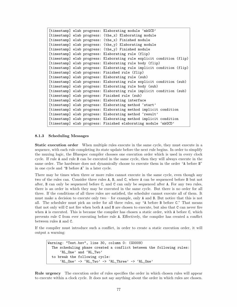
[timestamp] elab progress: Elaborating module ‘mkGCD’
[timestamp] elab progress: (the_x) Elaborating module
[timestamp] elab progress: (the_x) Finished module
[timestamp] elab progress: (the_y) Elaborating module
[timestamp] elab progress: (the_y) Finished module
[timestamp] elab progress: Elaborating rule (flip)
[timestamp] elab progress: Elaborating rule explicit condition (flip)
[timestamp] elab progress: Elaborating rule body (flip)
[timestamp] elab progress: Elaborating rule implicit condition (flip)
[timestamp] elab progress: Finished rule (flip)
[timestamp] elab progress: Elaborating rule (sub)
[timestamp] elab progress: Elaborating rule explicit condition (sub)
[timestamp] elab progress: Elaborating rule body (sub)
[timestamp] elab progress: Elaborating rule implicit condition (sub)
[timestamp] elab progress: Finished rule (sub)
[timestamp] elab progress: Elaborating interface
[timestamp] elab progress: Elaborating method ‘start’
[timestamp] elab progress: Elaborating method implicit condition
[timestamp] elab progress: Elaborating method ‘result’
[timestamp] elab progress: Elaborating method implicit condition
[timestamp] elab progress: Finished elaborating module ‘mkGCD’
8.1.3 Scheduling Messages
Static execution order When multiple rules execute in the same cycle, they must execute in asequence, with each rule completing its state update before the next rule begins. In order to simplifythe muxing logic, the Bluespec compiler chooses one execution order which is used in every clockcycle. If rule A and rule B can be executed in the same cycle, then they will always execute in thesame order. The hardware does not dynamically choose to execute them in the order “A before B”in one cycle and “B before A” in a later cycle.
There may be times when three or more rules cannot execute in the same cycle, even though anytwo of the rules can. Consider three rules A, B, and C, where A can be sequenced before B but notafter, B can only be sequenced before C, and C can only be sequenced after A. For any two rules,there is an order in which they may be executed in the same cycle. But there is no order for allthree. If the conditions of all three rules are satisfied, the scheduler cannot execute all of them. Itmust make a decision to execute only two – for example, only A and B. But notice that this is notall. The scheduler must pick an order for all three rules, say “A before B before C.” That meansthat not only will C not fire when both A and B are chosen to execute, but also that C can never firewhen A is executed. This is because the compiler has chosen a static order, with A before C, whichprevents rule C from ever executing before rule A. Effectively, the compiler has created a conflictbetween rules A and C.
If the compiler must introduce such a conflict, in order to create a static execution order, it willoutput a warning:
Warning: "Test.bsv", line 30, column 0: (G0009)
The scheduling phase created a conflict between the following rules:
‘RL_One’ and ‘RL_Two’
to break the following cycle:
‘RL_One’ -> ‘RL_Two’ -> ‘RL_Three’ -> ‘RL_One’
Rule urgency The execution order of rules specifies the order in which chosen rules will appearto execute within a clock cycle. It does not say anything about the order in which rules are chosen.
77
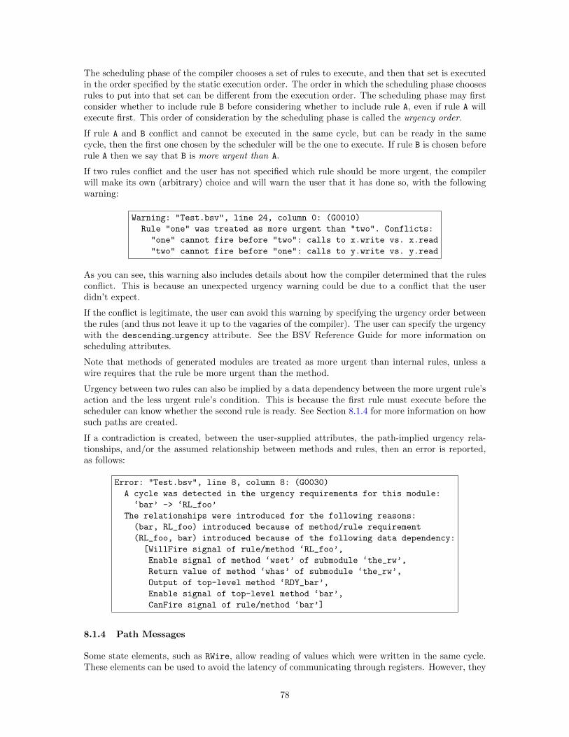
The scheduling phase of the compiler chooses a set of rules to execute, and then that set is executedin the order specified by the static execution order. The order in which the scheduling phase choosesrules to put into that set can be different from the execution order. The scheduling phase may firstconsider whether to include rule B before considering whether to include rule A, even if rule A willexecute first. This order of consideration by the scheduling phase is called the urgency order.
If rule A and B conflict and cannot be executed in the same cycle, but can be ready in the samecycle, then the first one chosen by the scheduler will be the one to execute. If rule B is chosen beforerule A then we say that B is more urgent than A.
If two rules conflict and the user has not specified which rule should be more urgent, the compilerwill make its own (arbitrary) choice and will warn the user that it has done so, with the followingwarning:
Warning: "Test.bsv", line 24, column 0: (G0010)
Rule "one" was treated as more urgent than "two". Conflicts:
"one" cannot fire before "two": calls to x.write vs. x.read
"two" cannot fire before "one": calls to y.write vs. y.read
As you can see, this warning also includes details about how the compiler determined that the rulesconflict. This is because an unexpected urgency warning could be due to a conflict that the userdidn’t expect.
If the conflict is legitimate, the user can avoid this warning by specifying the urgency order betweenthe rules (and thus not leave it up to the vagaries of the compiler). The user can specify the urgencywith the descending urgency attribute. See the BSV Reference Guide for more information onscheduling attributes.
Note that methods of generated modules are treated as more urgent than internal rules, unless awire requires that the rule be more urgent than the method.
Urgency between two rules can also be implied by a data dependency between the more urgent rule’saction and the less urgent rule’s condition. This is because the first rule must execute before thescheduler can know whether the second rule is ready. See Section 8.1.4 for more information on howsuch paths are created.
If a contradiction is created, between the user-supplied attributes, the path-implied urgency rela-tionships, and/or the assumed relationship between methods and rules, then an error is reported,as follows:
Error: "Test.bsv", line 8, column 8: (G0030)
A cycle was detected in the urgency requirements for this module:
‘bar’ -> ‘RL_foo’
The relationships were introduced for the following reasons:
(bar, RL_foo) introduced because of method/rule requirement
(RL_foo, bar) introduced because of the following data dependency:
[WillFire signal of rule/method ‘RL_foo’,
Enable signal of method ‘wset’ of submodule ‘the_rw’,
Return value of method ‘whas’ of submodule ‘the_rw’,
Output of top-level method ‘RDY_bar’,
Enable signal of top-level method ‘bar’,
CanFire signal of rule/method ‘bar’]
8.1.4 Path Messages
Some state elements, such as RWire, allow reading of values which were written in the same cycle.These elements can be used to avoid the latency of communicating through registers. However, they
78
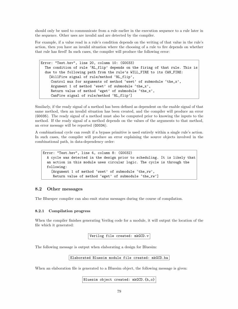
should only be used to communicate from a rule earlier in the execution sequence to a rule later inthe sequence. Other uses are invalid and are detected by the compiler.
For example, if a value read in a rule’s condition depends on the writing of that value in the rule’saction, then you have an invalid situation where the choosing of a rule to fire depends on whetherthat rule has fired! In such cases, the compiler will produce the following error:
Error: "Test.bsv", line 20, column 10: (G0033)
The condition of rule ‘RL_flip’ depends on the firing of that rule. This is
due to the following path from the rule’s WILL_FIRE to its CAN_FIRE:
[WillFire signal of rule/method ‘RL_flip’,
Control mux for arguments of method ‘wset’ of submodule ‘the_x’,
Argument 1 of method ‘wset’ of submodule ‘the_x’,
Return value of method ‘wget’ of submodule ‘the_x’,
CanFire signal of rule/method ‘RL_flip’]
Similarly, if the ready signal of a method has been defined as dependent on the enable signal of thatsame method, then an invalid situation has been created, and the compiler will produce an error(G0035). The ready signal of a method must also be computed prior to knowing the inputs to themethod. If the ready signal of a method depends on the values of the arguments to that method,an error message will be reported (G0034).
A combinational cycle can result if a bypass primitive is used entirely within a single rule’s action.In such cases, the compiler will produce an error explaining the source objects involved in thecombinational path, in data-dependency order:
Error: "Test.bsv", line 4, column 8: (G0032)
A cycle was detected in the design prior to scheduling. It is likely that
an action in this module uses circular logic. The cycle is through the
following:
[Argument 1 of method ‘wset’ of submodule ‘the_rw’,
Return value of method ‘wget’ of submodule ‘the_rw’]
8.2 Other messages
The Bluespec compiler can also emit status messages during the course of compilation.
8.2.1 Compilation progress
When the compiler finishes generating Verilog code for a module, it will output the location of thefile which it generated:
Verilog file created: mkGCD.v
The following message is output when elaborating a design for Bluesim:
Elaborated Bluesim module file created: mkGCD.ba
When an elaboration file is generated to a Bluesim object, the following message is given:
Bluesim object created: mkGCD.{h,o}
79
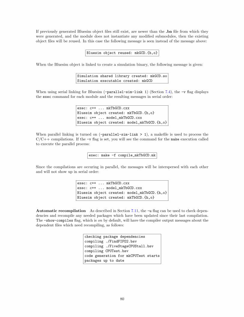
If previously generated Bluesim object files still exist, are newer than the .ba file from which theywere generated, and the module does not instantiate any modified submodules, then the existingobject files will be reused. In this case the following message is seen instead of the message above:
Bluesim object reused: mkGCD.{h,o}
When the Bluesim object is linked to create a simulation binary, the following message is given:
Simulation shared library created: mkGCD.so
Simulation executable created: mkGCD
When using serial linking for Bluesim (-parallel-sim-link 1) (Section 7.4), the -v flag displaysthe exec command for each module and the resulting messages in serial order:
exec: c++ ... mkTbGCD.cxx
Bluesim object created: mkTbGCD.{h,o}
exec: c++ ... model_mkTbGCD.cxx
Bluesim object created: model_mkTbGCD.{h,o}
When parallel linking is turned on (-parallel-sim-link > 1), a makefile is used to process theC/C++ compilations. If the -v flag is set, you will see the command for the make execution calledto execute the parallel process:
exec: make -f compile_mkTbGCD.mk
Since the compilations are occuring in parallel, the messages will be interspersed with each otherand will not show up in serial order:
exec: c++ ... mkTbGCD.cxx
exec: c++ ... model_mkTbGCD.cxx
Bluesim object created: model_mkTbGCD.{h,o}
Bluesim object created: mkTbGCD.{h,o}
Automatic recompilation As described in Section 7.11, the -u flag can be used to check depen-dencies and recompile any needed packages which have been updated since their last compilation.The -show-compiles flag, which is on by default, will have the compiler output messages about thedependent files which need recompiling, as follows:
checking package dependencies
compiling ./FindFIFO2.bsv
compiling ./FiveStageCPUStall.bsv
compiling CPUTest.bsv
code generation for mkCPUTest starts
packages up to date
80
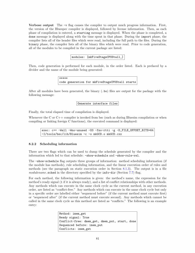
Verbose output The -v flag causes the compiler to output much progress information. First,the version of the Bluespec compiler is displayed, followed by license information. Then, as eachphase of compilation is entered, a starting message is displayed. When the phase is completed, adone message is displayed along with the time spent in that phase. During the import phase, thecompiler lists all of the header files which were read, including the full path to the files. During thebinary phase, the compiler lists all of the binary files which were read. Prior to code generation,all of the modules to be compiled in the current package are listed:
modules: [mkFiveStageCPUStall_]
Then, code generation is performed for each module, in the order listed. Each is prefaced by adivider and the name of the module being generated:
*****
code generation for mkFiveStageCPUStall starts
After all modules have been generated, the binary (.bo) files are output for the package with thefollowing message:
Generate interface files
Finally, the total elapsed time of compilation is displayed.
Whenever the C or C++ compiler is invoked from bsc (such as during Bluesim compilation or whencompiling or linking foreign C functions), the executed command is displayed:
exec: c++ -Wall -Wno-unused -O3 -fno-rtti -g -D_FILE_OFFSET_BITS=64
-I/tools/bsc/lib/Bluesim -c -o mkGCD.o mkGCD.cxx
8.2.2 Scheduling information
There are two flags which can be used to dump the schedule generated by the compiler and theinformation which led to that schedule: -show-schedule and -show-rule-rel.
The -show-schedule flag outputs three groups of information: method scheduling information (ifthe module has methods), rule scheduling information, and the linear execution order of rules andmethods (see the paragraph on static execution order in Section 8.1.3). The output is in a filemodulename.sched in the directory specified by the info-dir (Section 7.7) flag.
For each method, the following information is given: the method’s name, the expression for themethod’s ready signal (1 if it is always ready), and a list of conflict relationships with other methods.Any methods which can execute in the same clock cycle as the current method, in any executionorder, are listed as “conflict-free.” Any methods which can execute in the same clock cycle but onlyin a specific order are labelled either “sequenced before” (if the current method must execute first)or “sequenced after” (if the current method must execute second). Any methods which cannot becalled in the same clock cycle as this method are listed as “conflicts.” The following is an exampleentry:
Method: imem_get
Ready signal: True
Conflict-free: dmem_get, dmem_put, start, done
Sequenced before: imem_put
Conflicts: imem_get
81
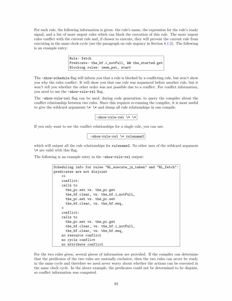
For each rule, the following information is given: the rule’s name, the expression for the rule’s readysignal, and a list of more urgent rules which can block the execution of this rule. The more urgentrules conflict with the current rule and, if chosen to execute, they will prevent the current rule fromexecuting in the same clock cycle (see the paragraph on rule urgency in Section 8.1.3). The followingis an example entry:
Rule: fetch
Predicate: the_bf.i_notFull_ && the_started.get
Blocking rules: imem_put, start
The -show-schedule flag will inform you that a rule is blocked by a conflicting rule, but won’t showyou why the rules conflict. It will show you that one rule was sequenced before another rule, but itwon’t tell you whether the other order was not possible due to a conflict. For conflict information,you need to use the -show-rule-rel flag.
The -show-rule-rel flag can be used, during code generation, to query the compiler about theconflict relationship between two rules. Since this requires re-running the compiler, it is most usefulto give the wildcard arguments \* \* and dump all rule relationships in one compile.
-show-rule-rel \* \*
If you only want to see the conflict relationships for a single rule, you can use:
-show-rule-rel \* rulename2
which will output all the rule relationships for rulename2. No other uses of the wildcard argument\* are valid with this flag.
The following is an example entry in the -show-rule-rel output:
Scheduling info for rules "RL_execute_jz_taken" and "RL_fetch":
predicates are not disjoint
<>
conflict:
calls to
the_pc.set vs. the_pc.get
the_bf.clear_ vs. the_bf.i_notFull_
the_pc.set vs. the_pc.set
the_bf.clear_ vs. the_bf.enq_
<
conflict:
calls to
the_pc.set vs. the_pc.get
the_bf.clear_ vs. the_bf.i_notFull_
the_bf.clear_ vs. the_bf.enq_
no resource conflict
no cycle conflict
no attribute conflict
For the two rules given, several pieces of information are provided. If the compiler can determinethat the predicates of the two rules are mutually exclusive, then the two rules can never be readyin the same cycle and therefore we need never worry about whether the actions can be executed inthe same clock cycle. In the above example, the predicates could not be determined to be disjoint,so conflict information was computed.
82

Two rules have a <>-type conflict if they use a pair of methods which are not conflict free. The ruleseither cannot be executed in the same clock cycle or they can but one must be sequenced first. Thecompiler lists the methods used in each rule which are the source of the conflict.
Two rules have a <-type conflict if the first rule mentioned cannot be executed in sequence beforethe second rule, because they use methods which cannot sequence in that order. There is no entryfor >-type conflicts; for that information, look for an entry for the two rules in the opposite orderand consult the <-type conflict. Again, the compiler lists the methods used in each rule which arethe source of the conflict.
If a conflict was introduced between two rules because of resource arbitration (see Section 7.6), thatinformation will be displayed third. The fourth line indicates whether a conflict was introducedto break an execution order cycle (see Section 8.1.3). The fifth, and last, line indicates whether aconflict was introduced by a scheduling attribute or operator in the design, such as the preempts
attribute (see the BSV Reference Guide for more information on pre-emption).
9 Verilog back end
The Verilog code produced by the BSV compiler can either be executed using standard Verilogexecution/interpretation tools or it can be compiled into netlists using standard synthesis tools.The generated code uses Bluespec-defined modules such as registers and FIFOs; these can be foundin $BLUESPECDIR/Verilog. These modules must be used for simulation or synthesis, though creatinga simulator with bsc -e automatically includes them. For example, to run the vcs simulator, usethe following command:
bsc -vsim vcs -e mkToplevel mkToplevel.v otherfiles.v
See Section 4.3.3 for details on choosing the Verilog simulator.
The $BLUESPECDIR/Verilog directory also contains the file Bluespec.xcf, a Xilinx XCF constraintfile, to be used when synthesizing with Xilinx.
9.1 Bluespec to Verilog mapping
To aid in the understanding and debugging of the generated Verilog code, this section describes thegeneral structure and name transformations that occur in mapping the original BSV source codeinto Verilog RTL. The section is based on a single example, which implements a greatest commondenominator (GCD) algorithm. The source BSV code for the example is shown in Figure 34. Thegenerated Verilog RTL is shown in Figures 35 and 36.
9.1.1 Interfaces and Ports
The interface section of a BSV design is used to specify the ports (input and outputs) of the generatedVerilog code. The BSV interface specification for the GCD example is repeated below.
interface ArithIO_IFC #(parameter type aTyp); // aTyp is a parameterized type
method Action start(aTyp num1, aTyp num2);
method aTyp result();
endinterface: ArithIO_IFC
This interface specification leads to the following Verilog port specification. In the BSV specificationshown in Figure 34, the type parameter aTyp has been bound to be a 51-bit integer.
83
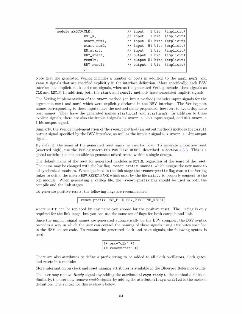
module mkGCD(CLK, // input 1 bit (implicit)
RST_N, // input 1 bit (implicit)
start_num1, // input 51 bits (explicit)
start_num2, // input 51 bits (explicit)
EN_start, // input 1 bit (implicit)
RDY_start, // output 1 bit (implicit)
result, // output 51 bits (explicit)
RDY_result // output 1 bit (implicit)
);
Note that the generated Verilog includes a number of ports in addition to the num1, num2, andresult signals that are specified explicitly in the interface definition. More specifically, each BSVinterface has implicit clock and reset signals, whereas the generated Verilog includes these signals asCLK and RST N. In addition, both the start and result methods have associated implicit signals.
The Verilog implementation of the start method (an input method) includes input signals for thearguments num1 and num2 which were explicitly declared in the BSV interface. The Verilog portnames corresponding to these inputs have the method name prepended, however, to avoid duplicateport names. They have the generated names start num1 and start num2. In addition to theseexplicit signals, there are also the implicit signals EN start, a 1-bit input signal, and RDY start, a1-bit output signal.
Similarly, the Verilog implementation of the result method (an output method) includes the resultoutput signal specified by the BSV interface, as well as the implicit signal RDY start, a 1-bit outputsignal.
By default, the sense of the generated reset signal is asserted low. To generate a positive reset(asserted high), use the Verilog macro BSV POSITIVE RESET, described in Section 4.3.3. This is aglobal switch; it is not possible to generate mixed resets within a single design.
The default name of the reset for generated modules is RST N, regardless of the sense of the reset.The name may be changed with the bsc flag -reset-prefix <name>, which assigns the new name toall synthesized modules. When specified in the link stage the -reset-prefix flag causes the Veriloglinker to define the macro BSV RESET NAME which used by the file main.v to properly connect to thetop module. When generating a Verilog file, the -reset-prefix flag should be used in both thecompile and the link stages.
To generate positive resets, the following flags are recommended:
-reset-prefix RST_P -D BSV_POSITIVE_RESET
where RST P can be replaced by any name you choose for the positive reset. The -D flag is onlyrequired for the link stage, but you can use the same set of flags for both compile and link.
Since the implicit signal names are generated automatically by the BSV compiler, the BSV syntaxprovides a way in which the user can control the naming of these signals using attributes specifiedin the BSV source code. To rename the generated clock and reset signals, the following syntax isused:
(* osc="clk" *)
(* reset="rst" *)
There are also attributes to define a prefix string to be added to all clock oscillators, clock gates,and resets in a module:
More information on clock and reset naming attributes is available in the Bluespec Reference Guide.
The user may remove Ready signals by adding the attribute always ready to the method definition.Similarly, the user may remove enable signals by adding the attribute always enabled to the methoddefinition. The syntax for this is shown below.
84
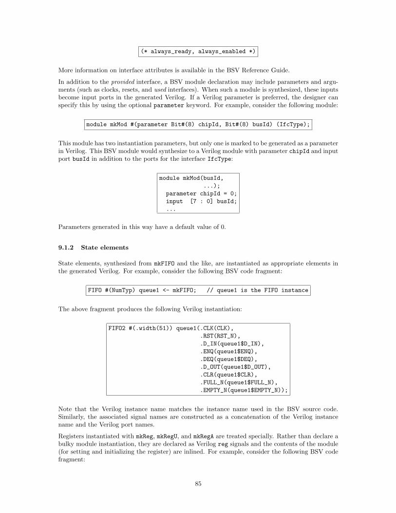
(* always_ready, always_enabled *)
More information on interface attributes is available in the BSV Reference Guide.
In addition to the provided interface, a BSV module declaration may include parameters and argu-ments (such as clocks, resets, and used interfaces). When such a module is synthesized, these inputsbecome input ports in the generated Verilog. If a Verilog parameter is preferred, the designer canspecify this by using the optional parameter keyword. For example, consider the following module:
module mkMod #(parameter Bit#(8) chipId, Bit#(8) busId) (IfcType);
This module has two instantiation parameters, but only one is marked to be generated as a parameterin Verilog. This BSV module would synthesize to a Verilog module with parameter chipId and inputport busId in addition to the ports for the interface IfcType:
module mkMod(busId,
...);
parameter chipId = 0;
input [7 : 0] busId;
...
Parameters generated in this way have a default value of 0.
9.1.2 State elements
State elements, synthesized from mkFIFO and the like, are instantiated as appropriate elements inthe generated Verilog. For example, consider the following BSV code fragment:
FIFO #(NumTyp) queue1 <- mkFIFO; // queue1 is the FIFO instance
The above fragment produces the following Verilog instantiation:
FIFO2 #(.width(51)) queue1(.CLK(CLK),
.RST(RST_N),
.D_IN(queue1$D_IN),
.ENQ(queue1$ENQ),
.DEQ(queue1$DEQ),
.D_OUT(queue1$D_OUT),
.CLR(queue1$CLR),
.FULL_N(queue1$FULL_N),
.EMPTY_N(queue1$EMPTY_N));
Note that the Verilog instance name matches the instance name used in the BSV source code.Similarly, the associated signal names are constructed as a concatenation of the Verilog instancename and the Verilog port names.
Registers instantiated with mkReg, mkRegU, and mkRegA are treated specially. Rather than declare abulky module instantiation, they are declared as Verilog reg signals and the contents of the module(for setting and initializing the register) are inlined. For example, consider the following BSV codefragment:
85
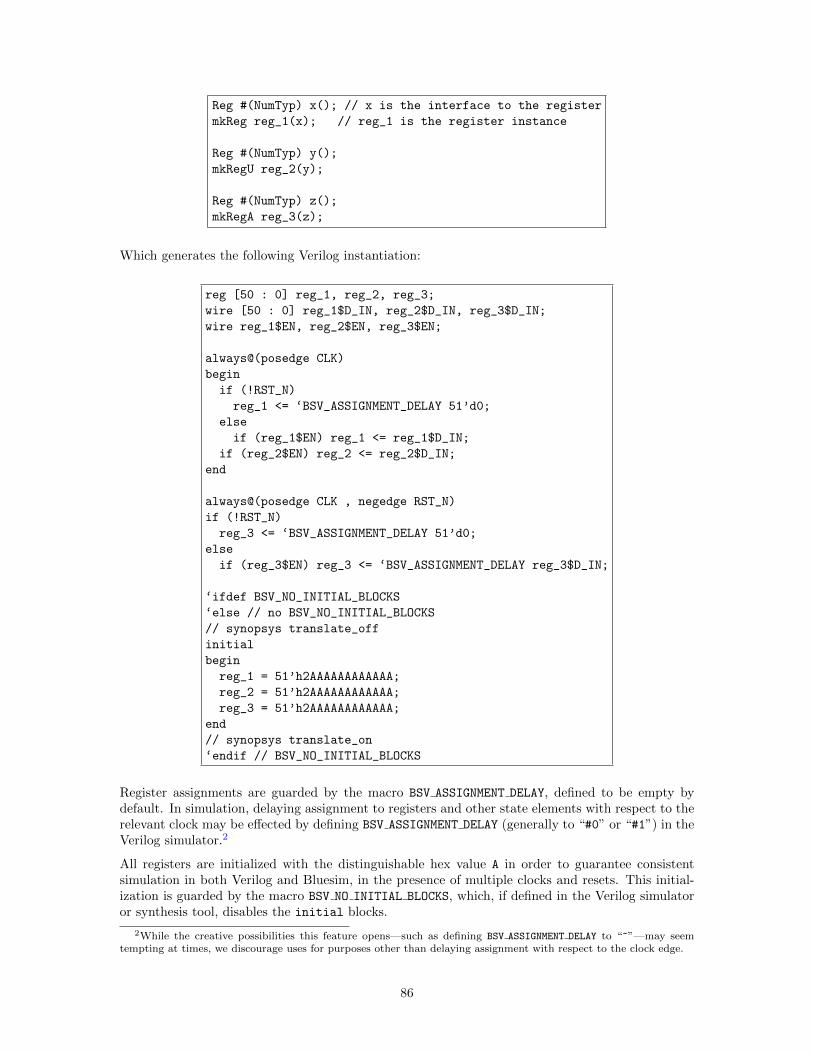
Reg #(NumTyp) x(); // x is the interface to the register
mkReg reg_1(x); // reg_1 is the register instance
Reg #(NumTyp) y();
mkRegU reg_2(y);
Reg #(NumTyp) z();
mkRegA reg_3(z);
Which generates the following Verilog instantiation:
reg [50 : 0] reg_1, reg_2, reg_3;
wire [50 : 0] reg_1$D_IN, reg_2$D_IN, reg_3$D_IN;
wire reg_1$EN, reg_2$EN, reg_3$EN;
always@(posedge CLK)
begin
if (!RST_N)
reg_1 <= ‘BSV_ASSIGNMENT_DELAY 51’d0;
else
if (reg_1$EN) reg_1 <= reg_1$D_IN;
if (reg_2$EN) reg_2 <= reg_2$D_IN;
end
always@(posedge CLK , negedge RST_N)
if (!RST_N)
reg_3 <= ‘BSV_ASSIGNMENT_DELAY 51’d0;
else
if (reg_3$EN) reg_3 <= ‘BSV_ASSIGNMENT_DELAY reg_3$D_IN;
‘ifdef BSV_NO_INITIAL_BLOCKS
‘else // no BSV_NO_INITIAL_BLOCKS
// synopsys translate_off
initial
begin
reg_1 = 51’h2AAAAAAAAAAAA;
reg_2 = 51’h2AAAAAAAAAAAA;
reg_3 = 51’h2AAAAAAAAAAAA;
end
// synopsys translate_on
‘endif // BSV_NO_INITIAL_BLOCKS
Register assignments are guarded by the macro BSV ASSIGNMENT DELAY, defined to be empty bydefault. In simulation, delaying assignment to registers and other state elements with respect to therelevant clock may be effected by defining BSV ASSIGNMENT DELAY (generally to “#0” or “#1”) in theVerilog simulator.2
All registers are initialized with the distinguishable hex value A in order to guarantee consistentsimulation in both Verilog and Bluesim, in the presence of multiple clocks and resets. This initial-ization is guarded by the macro BSV NO INITIAL BLOCKS, which, if defined in the Verilog simulatoror synthesis tool, disables the initial blocks.
2While the creative possibilities this feature opens—such as defining BSV ASSIGNMENT DELAY to “~”—may seemtempting at times, we discourage uses for purposes other than delaying assignment with respect to the clock edge.
86
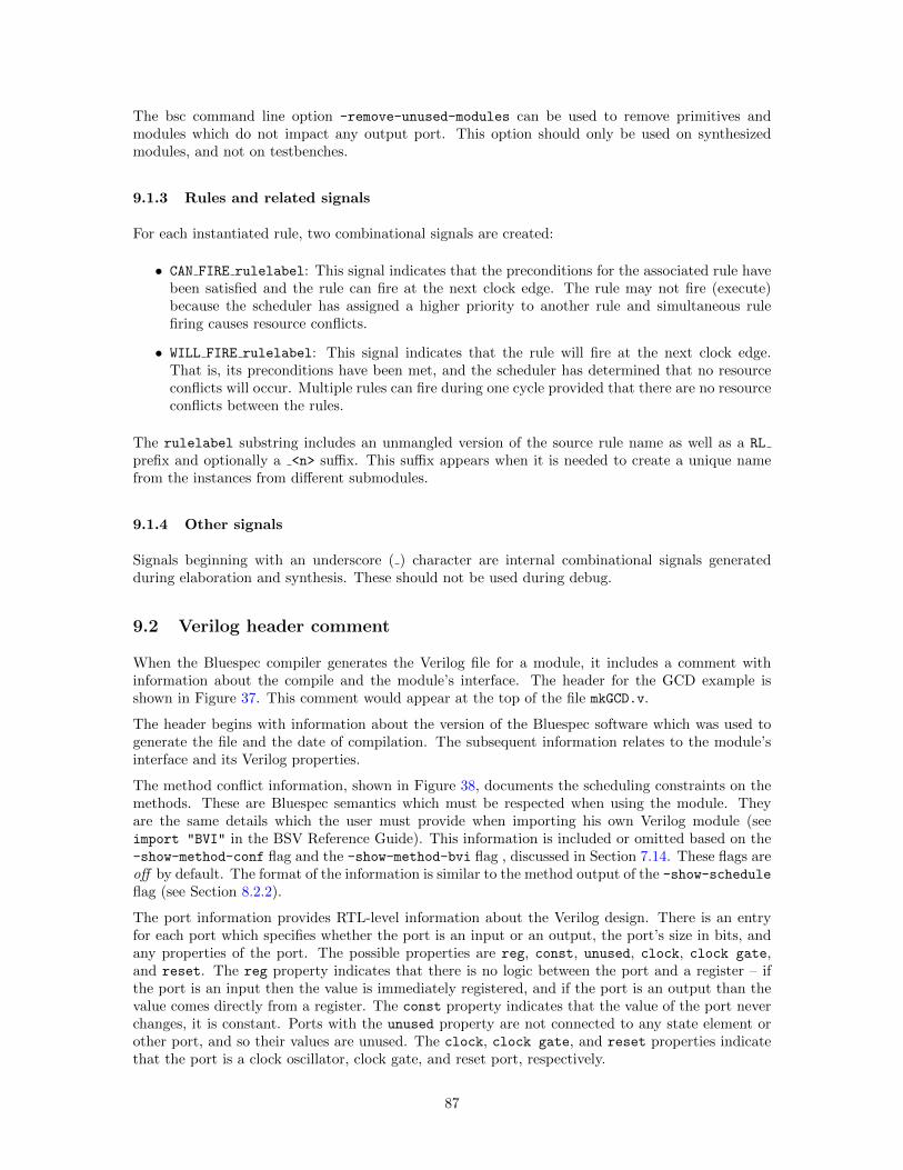
The bsc command line option -remove-unused-modules can be used to remove primitives andmodules which do not impact any output port. This option should only be used on synthesizedmodules, and not on testbenches.
9.1.3 Rules and related signals
For each instantiated rule, two combinational signals are created:
• CAN FIRE rulelabel: This signal indicates that the preconditions for the associated rule havebeen satisfied and the rule can fire at the next clock edge. The rule may not fire (execute)because the scheduler has assigned a higher priority to another rule and simultaneous rulefiring causes resource conflicts.
• WILL FIRE rulelabel: This signal indicates that the rule will fire at the next clock edge.That is, its preconditions have been met, and the scheduler has determined that no resourceconflicts will occur. Multiple rules can fire during one cycle provided that there are no resourceconflicts between the rules.
The rulelabel substring includes an unmangled version of the source rule name as well as a RL
prefix and optionally a <n> suffix. This suffix appears when it is needed to create a unique namefrom the instances from different submodules.
9.1.4 Other signals
Signals beginning with an underscore ( ) character are internal combinational signals generatedduring elaboration and synthesis. These should not be used during debug.
9.2 Verilog header comment
When the Bluespec compiler generates the Verilog file for a module, it includes a comment withinformation about the compile and the module’s interface. The header for the GCD example isshown in Figure 37. This comment would appear at the top of the file mkGCD.v.
The header begins with information about the version of the Bluespec software which was used togenerate the file and the date of compilation. The subsequent information relates to the module’sinterface and its Verilog properties.
The method conflict information, shown in Figure 38, documents the scheduling constraints on themethods. These are Bluespec semantics which must be respected when using the module. Theyare the same details which the user must provide when importing his own Verilog module (seeimport "BVI" in the BSV Reference Guide). This information is included or omitted based on the-show-method-conf flag and the -show-method-bvi flag , discussed in Section 7.14. These flags areoff by default. The format of the information is similar to the method output of the -show-scheduleflag (see Section 8.2.2).
The port information provides RTL-level information about the Verilog design. There is an entryfor each port which specifies whether the port is an input or an output, the port’s size in bits, andany properties of the port. The possible properties are reg, const, unused, clock, clock gate,and reset. The reg property indicates that there is no logic between the port and a register – ifthe port is an input then the value is immediately registered, and if the port is an output than thevalue comes directly from a register. The const property indicates that the value of the port neverchanges, it is constant. Ports with the unused property are not connected to any state element orother port, and so their values are unused. The clock, clock gate, and reset properties indicatethat the port is a clock oscillator, clock gate, and reset port, respectively.
87
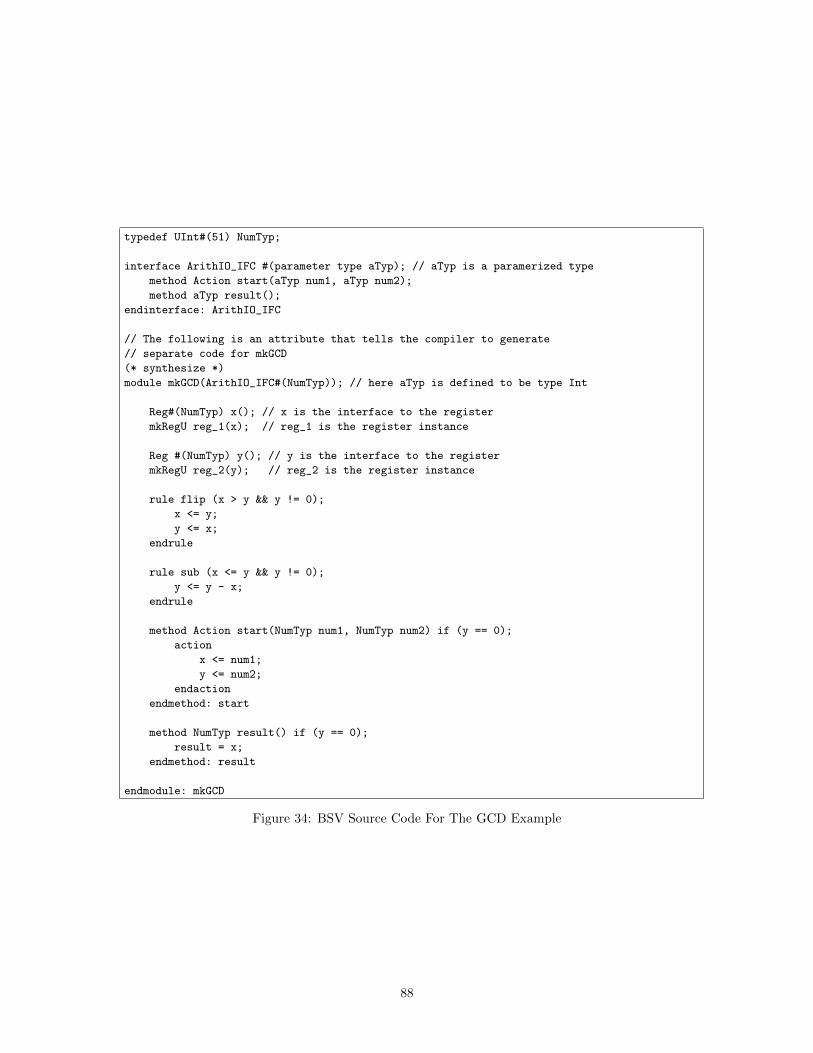
typedef UInt#(51) NumTyp;
interface ArithIO_IFC #(parameter type aTyp); // aTyp is a paramerized type
method Action start(aTyp num1, aTyp num2);
method aTyp result();
endinterface: ArithIO_IFC
// The following is an attribute that tells the compiler to generate
// separate code for mkGCD
(* synthesize *)
module mkGCD(ArithIO_IFC#(NumTyp)); // here aTyp is defined to be type Int
Reg#(NumTyp) x(); // x is the interface to the register
mkRegU reg_1(x); // reg_1 is the register instance
Reg #(NumTyp) y(); // y is the interface to the register
mkRegU reg_2(y); // reg_2 is the register instance
rule flip (x > y && y != 0);
x <= y;
y <= x;
endrule
rule sub (x <= y && y != 0);
y <= y - x;
endrule
method Action start(NumTyp num1, NumTyp num2) if (y == 0);
action
x <= num1;
y <= num2;
endaction
endmethod: start
method NumTyp result() if (y == 0);
result = x;
endmethod: result
endmodule: mkGCD
Figure 34: BSV Source Code For The GCD Example
88
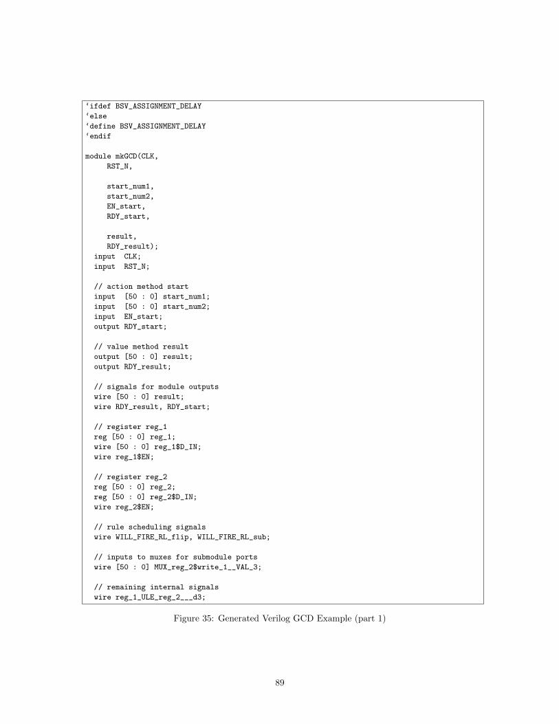
‘ifdef BSV_ASSIGNMENT_DELAY
‘else
‘define BSV_ASSIGNMENT_DELAY
‘endif
module mkGCD(CLK,
RST_N,
start_num1,
start_num2,
EN_start,
RDY_start,
result,
RDY_result);
input CLK;
input RST_N;
// action method start
input [50 : 0] start_num1;
input [50 : 0] start_num2;
input EN_start;
output RDY_start;
// value method result
output [50 : 0] result;
output RDY_result;
// signals for module outputs
wire [50 : 0] result;
wire RDY_result, RDY_start;
// register reg_1
reg [50 : 0] reg_1;
wire [50 : 0] reg_1$D_IN;
wire reg_1$EN;
// register reg_2
reg [50 : 0] reg_2;
reg [50 : 0] reg_2$D_IN;
wire reg_2$EN;
// rule scheduling signals
wire WILL_FIRE_RL_flip, WILL_FIRE_RL_sub;
// inputs to muxes for submodule ports
wire [50 : 0] MUX_reg_2$write_1__VAL_3;
// remaining internal signals
wire reg_1_ULE_reg_2___d3;
Figure 35: Generated Verilog GCD Example (part 1)
89
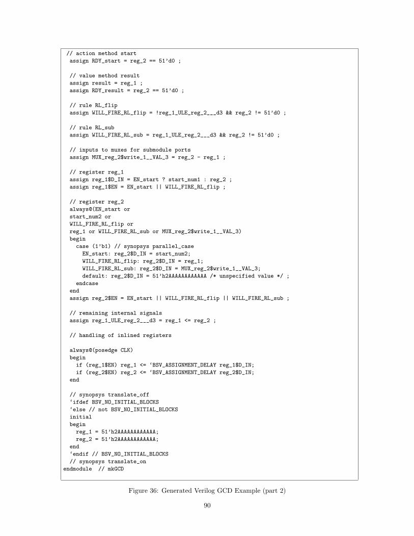
// action method start
assign RDY_start = reg_2 == 51’d0 ;
// value method result
assign result = reg_1 ;
assign RDY_result = reg_2 == 51’d0 ;
// rule RL_flip
assign WILL_FIRE_RL_flip = !reg_1_ULE_reg_2___d3 && reg_2 != 51’d0 ;
// rule RL_sub
assign WILL_FIRE_RL_sub = reg_1_ULE_reg_2___d3 && reg_2 != 51’d0 ;
// inputs to muxes for submodule ports
assign MUX_reg_2$write_1__VAL_3 = reg_2 - reg_1 ;
// register reg_1
assign reg_1$D_IN = EN_start ? start_num1 : reg_2 ;
assign reg_1$EN = EN_start || WILL_FIRE_RL_flip ;
// register reg_2
always@(EN_start or
start_num2 or
WILL_FIRE_RL_flip or
reg_1 or WILL_FIRE_RL_sub or MUX_reg_2$write_1__VAL_3)
begin
case (1’b1) // synopsys parallel_case
EN_start: reg_2$D_IN = start_num2;
WILL_FIRE_RL_flip: reg_2$D_IN = reg_1;
WILL_FIRE_RL_sub: reg_2$D_IN = MUX_reg_2$write_1__VAL_3;
default: reg_2$D_IN = 51’h2AAAAAAAAAAAA /* unspecified value */ ;
endcase
end
assign reg_2$EN = EN_start || WILL_FIRE_RL_flip || WILL_FIRE_RL_sub ;
// remaining internal signals
assign reg_1_ULE_reg_2___d3 = reg_1 <= reg_2 ;
// handling of inlined registers
always@(posedge CLK)
begin
if (reg_1$EN) reg_1 <= ‘BSV_ASSIGNMENT_DELAY reg_1$D_IN;
if (reg_2$EN) reg_2 <= ‘BSV_ASSIGNMENT_DELAY reg_2$D_IN;
end
// synopsys translate_off
‘ifdef BSV_NO_INITIAL_BLOCKS
‘else // not BSV_NO_INITIAL_BLOCKS
initial
begin
reg_1 = 51’h2AAAAAAAAAAAA;
reg_2 = 51’h2AAAAAAAAAAAA;
end
‘endif // BSV_NO_INITIAL_BLOCKS
// synopsys translate_on
endmodule // mkGCD
Figure 36: Generated Verilog GCD Example (part 2)
90
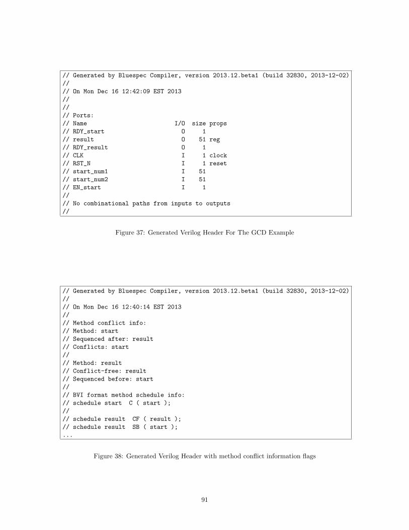
// Generated by Bluespec Compiler, version 2013.12.beta1 (build 32830, 2013-12-02)
//
// On Mon Dec 16 12:42:09 EST 2013
//
//
// Ports:
// Name I/O size props
// RDY_start O 1
// result O 51 reg
// RDY_result O 1
// CLK I 1 clock
// RST_N I 1 reset
// start_num1 I 51
// start_num2 I 51
// EN_start I 1
//
// No combinational paths from inputs to outputs
//
Figure 37: Generated Verilog Header For The GCD Example
// Generated by Bluespec Compiler, version 2013.12.beta1 (build 32830, 2013-12-02)
//
// On Mon Dec 16 12:40:14 EST 2013
//
// Method conflict info:
// Method: start
// Sequenced after: result
// Conflicts: start
//
// Method: result
// Conflict-free: result
// Sequenced before: start
//
// BVI format method schedule info:
// schedule start C ( start );
//
// schedule result CF ( result );
// schedule result SB ( start );
...
Figure 38: Generated Verilog Header with method conflict information flags
91
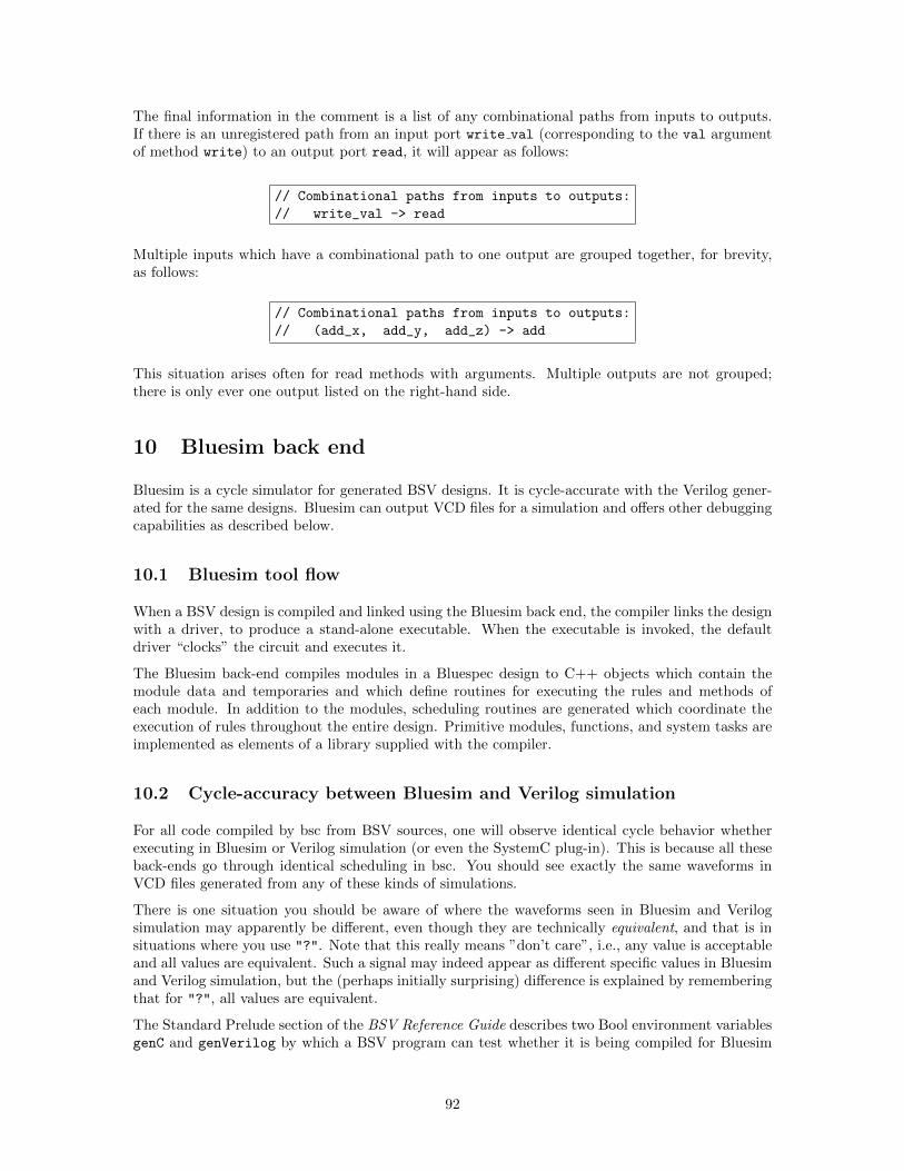
The final information in the comment is a list of any combinational paths from inputs to outputs.If there is an unregistered path from an input port write val (corresponding to the val argumentof method write) to an output port read, it will appear as follows:
// Combinational paths from inputs to outputs:
// write_val -> read
Multiple inputs which have a combinational path to one output are grouped together, for brevity,as follows:
// Combinational paths from inputs to outputs:
// (add_x, add_y, add_z) -> add
This situation arises often for read methods with arguments. Multiple outputs are not grouped;there is only ever one output listed on the right-hand side.
10 Bluesim back end
Bluesim is a cycle simulator for generated BSV designs. It is cycle-accurate with the Verilog gener-ated for the same designs. Bluesim can output VCD files for a simulation and offers other debuggingcapabilities as described below.
10.1 Bluesim tool flow
When a BSV design is compiled and linked using the Bluesim back end, the compiler links the designwith a driver, to produce a stand-alone executable. When the executable is invoked, the defaultdriver “clocks” the circuit and executes it.
The Bluesim back-end compiles modules in a Bluespec design to C++ objects which contain themodule data and temporaries and which define routines for executing the rules and methods ofeach module. In addition to the modules, scheduling routines are generated which coordinate theexecution of rules throughout the entire design. Primitive modules, functions, and system tasks areimplemented as elements of a library supplied with the compiler.
10.2 Cycle-accuracy between Bluesim and Verilog simulation
For all code compiled by bsc from BSV sources, one will observe identical cycle behavior whetherexecuting in Bluesim or Verilog simulation (or even the SystemC plug-in). This is because all theseback-ends go through identical scheduling in bsc. You should see exactly the same waveforms inVCD files generated from any of these kinds of simulations.
There is one situation you should be aware of where the waveforms seen in Bluesim and Verilogsimulation may apparently be different, even though they are technically equivalent, and that is insituations where you use "?". Note that this really means ”don’t care”, i.e., any value is acceptableand all values are equivalent. Such a signal may indeed appear as different specific values in Bluesimand Verilog simulation, but the (perhaps initially surprising) difference is explained by rememberingthat for "?", all values are equivalent.
The Standard Prelude section of the BSV Reference Guide describes two Bool environment variablesgenC and genVerilog by which a BSV program can test whether it is being compiled for Bluesim
92
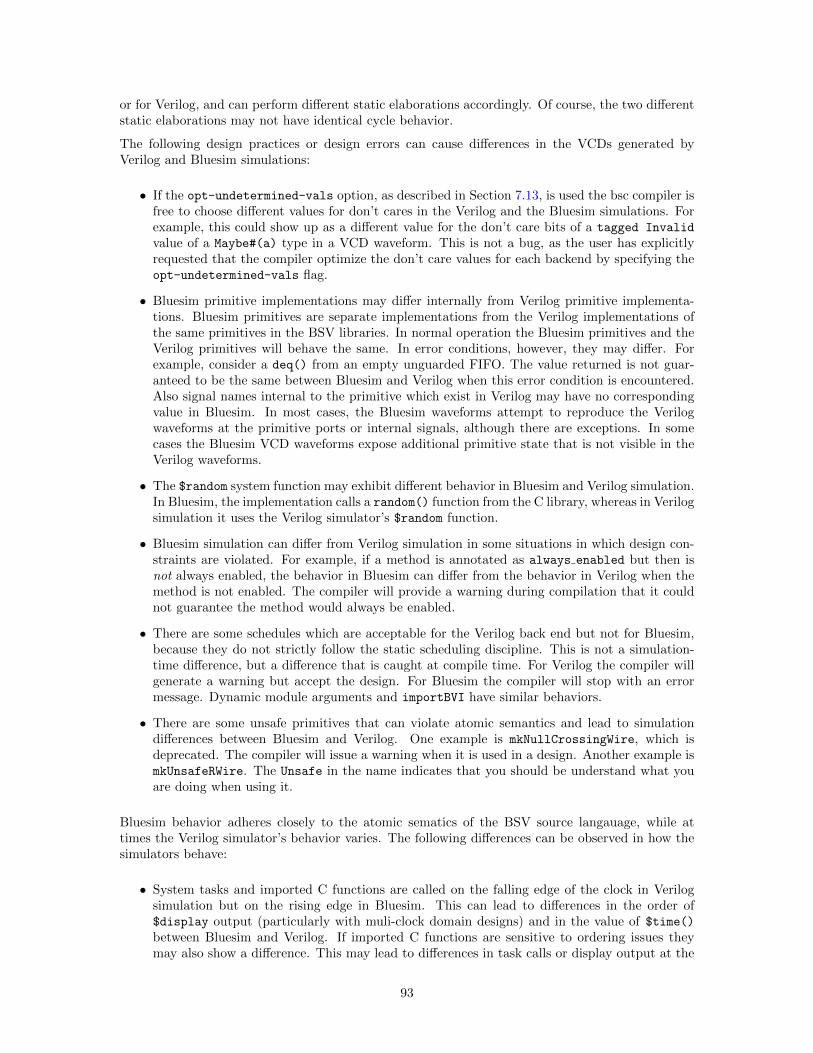
or for Verilog, and can perform different static elaborations accordingly. Of course, the two differentstatic elaborations may not have identical cycle behavior.
The following design practices or design errors can cause differences in the VCDs generated byVerilog and Bluesim simulations:
• If the opt-undetermined-vals option, as described in Section 7.13, is used the bsc compiler isfree to choose different values for don’t cares in the Verilog and the Bluesim simulations. Forexample, this could show up as a different value for the don’t care bits of a tagged Invalid
value of a Maybe#(a) type in a VCD waveform. This is not a bug, as the user has explicitlyrequested that the compiler optimize the don’t care values for each backend by specifying theopt-undetermined-vals flag.
• Bluesim primitive implementations may differ internally from Verilog primitive implementa-tions. Bluesim primitives are separate implementations from the Verilog implementations ofthe same primitives in the BSV libraries. In normal operation the Bluesim primitives and theVerilog primitives will behave the same. In error conditions, however, they may differ. Forexample, consider a deq() from an empty unguarded FIFO. The value returned is not guar-anteed to be the same between Bluesim and Verilog when this error condition is encountered.Also signal names internal to the primitive which exist in Verilog may have no correspondingvalue in Bluesim. In most cases, the Bluesim waveforms attempt to reproduce the Verilogwaveforms at the primitive ports or internal signals, although there are exceptions. In somecases the Bluesim VCD waveforms expose additional primitive state that is not visible in theVerilog waveforms.
• The $random system function may exhibit different behavior in Bluesim and Verilog simulation.In Bluesim, the implementation calls a random() function from the C library, whereas in Verilogsimulation it uses the Verilog simulator’s $random function.
• Bluesim simulation can differ from Verilog simulation in some situations in which design con-straints are violated. For example, if a method is annotated as always enabled but then isnot always enabled, the behavior in Bluesim can differ from the behavior in Verilog when themethod is not enabled. The compiler will provide a warning during compilation that it couldnot guarantee the method would always be enabled.
• There are some schedules which are acceptable for the Verilog back end but not for Bluesim,because they do not strictly follow the static scheduling discipline. This is not a simulation-time difference, but a difference that is caught at compile time. For Verilog the compiler willgenerate a warning but accept the design. For Bluesim the compiler will stop with an errormessage. Dynamic module arguments and importBVI have similar behaviors.
• There are some unsafe primitives that can violate atomic semantics and lead to simulationdifferences between Bluesim and Verilog. One example is mkNullCrossingWire, which isdeprecated. The compiler will issue a warning when it is used in a design. Another example ismkUnsafeRWire. The Unsafe in the name indicates that you should be understand what youare doing when using it.
Bluesim behavior adheres closely to the atomic sematics of the BSV source langauage, while attimes the Verilog simulator’s behavior varies. The following differences can be observed in how thesimulators behave:
• System tasks and imported C functions are called on the falling edge of the clock in Verilogsimulation but on the rising edge in Bluesim. This can lead to differences in the order of$display output (particularly with muli-clock domain designs) and in the value of $time()
between Bluesim and Verilog. If imported C functions are sensitive to ordering issues theymay also show a difference. This may lead to differences in task calls or display output at the
93
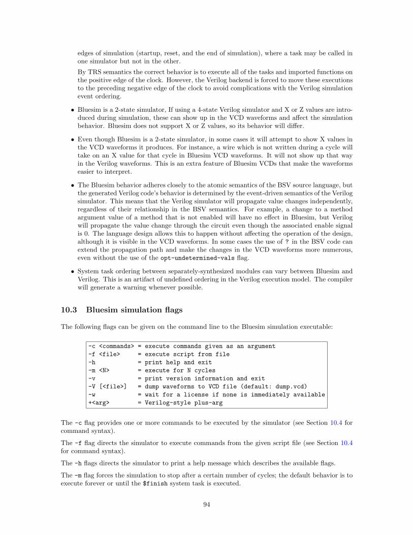
edges of simulation (startup, reset, and the end of simulation), where a task may be called inone simulator but not in the other.
By TRS semantics the correct behavior is to execute all of the tasks and imported functions onthe positive edge of the clock. However, the Verilog backend is forced to move these executionsto the preceding negative edge of the clock to avoid complications with the Verilog simulationevent ordering.
• Bluesim is a 2-state simulator, If using a 4-state Verilog simulator and X or Z values are intro-duced during simulation, these can show up in the VCD waveforms and affect the simulationbehavior. Bluesim does not support X or Z values, so its behavior will differ.
• Even though Bluesim is a 2-state simulator, in some cases it will attempt to show X values inthe VCD waveforms it produces. For instance, a wire which is not written during a cycle willtake on an X value for that cycle in Bluesim VCD waveforms. It will not show up that wayin the Verilog waveforms. This is an extra feature of Bluesim VCDs that make the waveformseasier to interpret.
• The Bluesim behavior adheres closely to the atomic semantics of the BSV source language, butthe generated Verilog code’s behavior is determined by the event-driven semantics of the Verilogsimulator. This means that the Verilog simulator will propagate value changes independently,regardless of their relationship in the BSV semantics. For example, a change to a methodargument value of a method that is not enabled will have no effect in Bluesim, but Verilogwill propagate the value change through the circuit even though the associated enable signalis 0. The language design allows this to happen without affecting the operation of the design,although it is visible in the VCD waveforms. In some cases the use of ? in the BSV code canextend the propagation path and make the changes in the VCD waveforms more numerous,even without the use of the opt-undetermined-vals flag.
• System task ordering between separately-synthesized modules can vary between Bluesim andVerilog. This is an artifact of undefined ordering in the Verilog execution model. The compilerwill generate a warning whenever possible.
10.3 Bluesim simulation flags
The following flags can be given on the command line to the Bluesim simulation executable:
-c <commands> = execute commands given as an argument
-f <file> = execute script from file
-h = print help and exit
-m <N> = execute for N cycles
-v = print version information and exit
-V [<file>] = dump waveforms to VCD file (default: dump.vcd)
-w = wait for a license if none is immediately available
+<arg> = Verilog-style plus-arg
The -c flag provides one or more commands to be executed by the simulator (see Section 10.4 forcommand syntax).
The -f flag directs the simulator to execute commands from the given script file (see Section 10.4for command syntax).
The -h flags directs the simulator to print a help message which describes the available flags.
The -m flag forces the simulation to stop after a certain number of cycles; the default behavior is toexecute forever or until the $finish system task is executed.
94
The -v flag directs the simulator to print some version information related to the simulation model,including the compiler version used to create it and the time and date at which it was created.
The -V flag causes the simulator to dump waveforms to a VCD file. If a file name is provided thewaveforms will be written the named file, otherwise the default file name “dump.vcd” will be used.
The -w flag directs the simulator to wait for a license to become available when none is availableimmediately. Without the -w flag, the simulator will exit if it no license is available. You can generateBluesim models which do not require a Bluesim license at runtime by using the no-untimed-licenseflag (Section 7.8).
Arguments can be passed to the simulation model with +<arg>. These values can be tested by theBSV model via the $test$plusargs system task.
10.4 Interactive simulation
The simulator can be executed in an interactive or scripted mode. Commands and scripts can begiven using the -c and -f flags. Alternatively, the simulation object can be loaded directly in Bluetclusing the sim load command.
Bluetcl extends a TCL shell with a sim command whose subcommands control all aspects of loading,executing and interacting with a Bluesim simulation object. For a list of Bluetcl sim subcommands,see the Bluetcl appendix B.4.2.
There are two ways to access these simulation commands, through scripting or interactively. Whena model is compiled through the Bluesim backend, it generates a .so file containing the simulationobject. It also generates an executable program that provides a convenient way to run and use thesimulation object. Passing the -c or -f flags to the executable enables scripting the simulation.
To run the simulation interactively, the standard Bluetcl tool, described in Appendix B, should beused.
In addition to these actions accessible through the sim command, all of the normal functions of aTCL interpreter as well as additional Bluespec-specific extensions are available in Bluetcl and theycan be freely intermixed.
Note that the TCL interpreter behaves differently when executing a script than when runninginteractively. In an interactive session, the TCL interpreter will print the value returned by eachcommand (if any), but when executing a script output is only generated in response to an explicitoutput command (eg. puts).
Loading Bluesim
Before executing Bluesim commands interactively, the Bluesim package must be loaded into Bluetcland the namespace must be imported. This is done automatically when using the -c and -f flags,but must be done manually when running interactively.
From Bluetcl, the following commands must be entered at the start of the interactive session, toload the Bluesim package and import the Bluesim namespace:
package require Bluesim
namespace import Bluesim::*
95
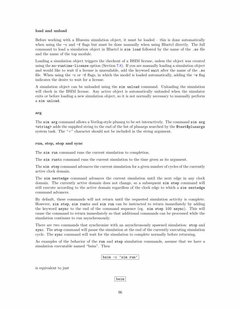
load and unload
Before working with a Bluesim simulation object, it must be loaded – this is done automaticallywhen using the -c and -f flags but must be done manually when using Bluetcl directly. The fullcommand to load a simulation object in Bluetcl is sim load followed by the name of the .so fileand the name of the top module.
Loading a simulation object triggers the checkout of a BSIM license, unless the object was createdusing the no-runtime-license option (Section 7.8). If you are manually loading a simulation objectand would like to wait if a license is unavailable, add the keyword wait after the name of the .so
file. When using the -c or -f flags, in which the model is loaded automatically, adding the -w flagindicates the desire to wait for a license.
A simulation object can be unloaded using the sim unload command. Unloading the simulationwill check in the BSIM license. Any active object is automatically unloaded when the simulatorexits or before loading a new simulation object, so it is not normally necessary to manually performa sim unload.
arg
The sim arg command allows a Verilog-style plusarg to be set interactively. The command sim arg
<string> adds the supplied string to the end of the list of plusargs searched by the $test$plusargssystem task. The “+” character should not be included in the string argument.
run, step, stop and sync
The sim run command runs the current simulation to completion.
The sim runto command runs the current simulation to the time given as its argument.
The sim step command advances the current simulation for a given number of cycles of the currentlyactive clock domain.
The sim nextedge command advances the current simulation until the next edge in any clockdomain. The currently active domain does not change, so a subsequent sim step command willstill execute according to the active domain regardless of the clock edge to which a sim nextedge
command advances.
By default, these commands will not return until the requested simulation activity is complete.However, sim step, sim runto and sim run can be instructed to return immediately by addingthe keyword async to the end of the command sequence (eg. sim step 100 async). This willcause the command to return immediately so that additional commands can be processed while thesimulation continues to run asynchronously.
There are two commands that synchronize with an asynchronously spawned simulation: stop andsync. The stop command will pause the simulation at the end of the currently executing simulationcycle. The sync command will wait for the simulation to complete normally before returning.
As examples of the behavior of the run and step simulation commands, assume that we have asimulation executable named “bsim”. Then
bsim -c ’sim run’
is equivalent to just
bsim
96
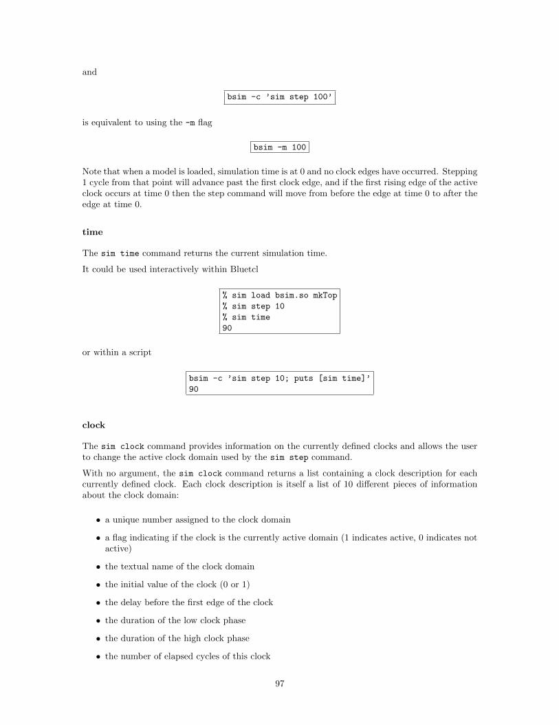
and
bsim -c ’sim step 100’
is equivalent to using the -m flag
bsim -m 100
Note that when a model is loaded, simulation time is at 0 and no clock edges have occurred. Stepping1 cycle from that point will advance past the first clock edge, and if the first rising edge of the activeclock occurs at time 0 then the step command will move from before the edge at time 0 to after theedge at time 0.
time
The sim time command returns the current simulation time.
It could be used interactively within Bluetcl
% sim load bsim.so mkTop
% sim step 10
% sim time
90
or within a script
bsim -c ’sim step 10; puts [sim time]’
90
clock
The sim clock command provides information on the currently defined clocks and allows the userto change the active clock domain used by the sim step command.
With no argument, the sim clock command returns a list containing a clock description for eachcurrently defined clock. Each clock description is itself a list of 10 different pieces of informationabout the clock domain:
• a unique number assigned to the clock domain
• a flag indicating if the clock is the currently active domain (1 indicates active, 0 indicates notactive)
• the textual name of the clock domain
• the initial value of the clock (0 or 1)
• the delay before the first edge of the clock
• the duration of the low clock phase
• the duration of the high clock phase
• the number of elapsed cycles of this clock
97
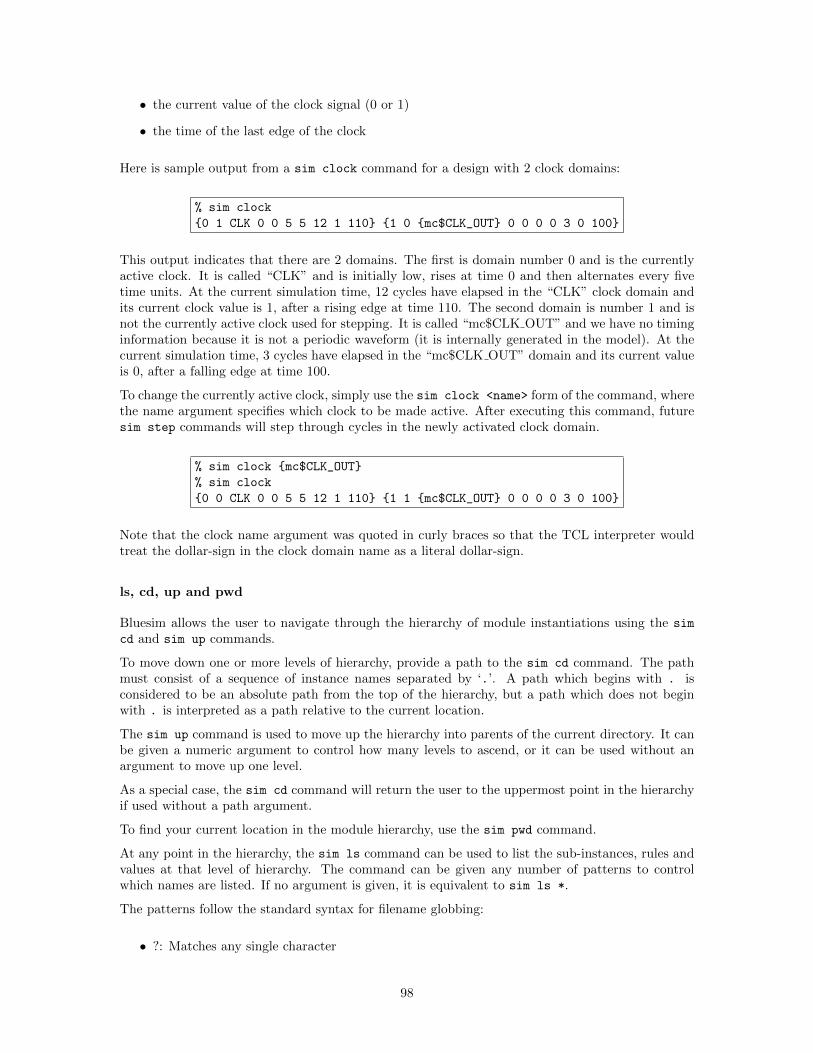
• the current value of the clock signal (0 or 1)
• the time of the last edge of the clock
Here is sample output from a sim clock command for a design with 2 clock domains:
% sim clock
{0 1 CLK 0 0 5 5 12 1 110} {1 0 {mc$CLK_OUT} 0 0 0 0 3 0 100}
This output indicates that there are 2 domains. The first is domain number 0 and is the currentlyactive clock. It is called “CLK” and is initially low, rises at time 0 and then alternates every fivetime units. At the current simulation time, 12 cycles have elapsed in the “CLK” clock domain andits current clock value is 1, after a rising edge at time 110. The second domain is number 1 and isnot the currently active clock used for stepping. It is called “mc$CLK OUT” and we have no timinginformation because it is not a periodic waveform (it is internally generated in the model). At thecurrent simulation time, 3 cycles have elapsed in the “mc$CLK OUT” domain and its current valueis 0, after a falling edge at time 100.
To change the currently active clock, simply use the sim clock <name> form of the command, wherethe name argument specifies which clock to be made active. After executing this command, futuresim step commands will step through cycles in the newly activated clock domain.
% sim clock {mc$CLK_OUT}
% sim clock
{0 0 CLK 0 0 5 5 12 1 110} {1 1 {mc$CLK_OUT} 0 0 0 0 3 0 100}
Note that the clock name argument was quoted in curly braces so that the TCL interpreter wouldtreat the dollar-sign in the clock domain name as a literal dollar-sign.
ls, cd, up and pwd
Bluesim allows the user to navigate through the hierarchy of module instantiations using the sim
cd and sim up commands.
To move down one or more levels of hierarchy, provide a path to the sim cd command. The pathmust consist of a sequence of instance names separated by ‘.’. A path which begins with . isconsidered to be an absolute path from the top of the hierarchy, but a path which does not beginwith . is interpreted as a path relative to the current location.
The sim up command is used to move up the hierarchy into parents of the current directory. It canbe given a numeric argument to control how many levels to ascend, or it can be used without anargument to move up one level.
As a special case, the sim cd command will return the user to the uppermost point in the hierarchyif used without a path argument.
To find your current location in the module hierarchy, use the sim pwd command.
At any point in the hierarchy, the sim ls command can be used to list the sub-instances, rules andvalues at that level of hierarchy. The command can be given any number of patterns to controlwhich names are listed. If no argument is given, it is equivalent to sim ls *.
The patterns follow the standard syntax for filename globbing:
• ?: Matches any single character
98
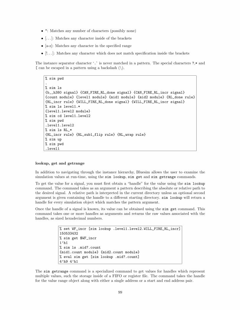
• *: Matches any number of characters (possibly none)
• [. . . ]: Matches any character inside of the brackets
• [a-z]: Matches any character in the specified range
• [!. . . ]: Matches any character which does not match specification inside the brackets
The instance separator character ‘.’ is never matched in a pattern. The special characters ?,* and[ can be escaped in a pattern using a backslash (\).
% sim pwd
.
% sim ls
{b__h380 signal} {CAN_FIRE_RL_done signal} {CAN_FIRE_RL_incr signal}
{count module} {level1 module} {mid1 module} {mid2 module} {RL_done rule}
{RL_incr rule} {WILL_FIRE_RL_done signal} {WILL_FIRE_RL_incr signal}
% sim ls level1.*
{level1.level2 module}
% sim cd level1.level2
% sim pwd
.level1.level2
% sim ls RL_*
{RL_incr rule} {RL_sub1_flip rule} {RL_wrap rule}
% sim up
% sim pwd
.level1
lookup, get and getrange
In addition to navigating through the instance hierarchy, Bluesim allows the user to examine thesimulation values at run-time, using the sim lookup, sim get and sim getrange commands.
To get the value for a signal, you must first obtain a “handle” for the value using the sim lookup
command. The command takes as an argument a pattern describing the absolute or relative path tothe desired signal. A relative path is interpreted in the current directory unless an optional secondargument is given containing the handle to a different starting directory. sim lookup will return ahandle for every simulation object which matches the pattern argument.
Once the handle of a signal is known, its value can be obtained using the sim get command. Thiscommand takes one or more handles as arguments and returns the raw values associated with thehandles, as sized hexadecimal numbers.
% set WF_incr [sim lookup .level1.level2.WILL_FIRE_RL_incr]
150533432
% sim get $WF_incr
1’h1
% sim ls .mid?.count
{mid1.count module} {mid2.count module}
% eval sim get [sim lookup .mid?.count]
4’h9 4’h1
The sim getrange command is a specialized command to get values for handles which representmultiple values, such the storage inside of a FIFO or register file. The command takes the handlefor the value range object along with either a single address or a start and end address pair.
99
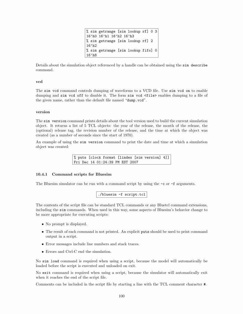
% sim getrange [sim lookup rf] 0 3
16’h0 16’h1 16’h2 16’h3
% sim getrange [sim lookup rf] 2
16’h2
% sim getrange [sim lookup fifo] 0
16’h8
Details about the simulation object referenced by a handle can be obtained using the sim describe
command.
vcd
The sim vcd command controls dumping of waveforms to a VCD file. Use sim vcd on to enabledumping and sim vcd off to disable it. The form sim vcd <file> enables dumping to a file ofthe given name, rather than the default file named “dump.vcd”.
version
The sim version command prints details about the tool version used to build the current simulationobject. It returns a list of 5 TCL objects: the year of the release, the month of the release, the(optional) release tag, the revision number of the release, and the time at which the object wascreated (as a number of seconds since the start of 1970).
An example of using the sim version command to print the date and time at which a simulationobject was created:
% puts [clock format [lindex [sim version] 4]]
Fri Dec 14 01:24:39 PM EST 2007
10.4.1 Command scripts for Bluesim
The Bluesim simulator can be run with a command script by using the -c or -f arguments.
./bluesim -f script.tcl
The contents of the script file can be standard TCL commands or any Bluetcl command extensions,including the sim commands. When used in this way, some aspects of Bluesim’s behavior change tobe more appropriate for executing scripts:
• No prompt is displayed.
• The result of each command is not printed. An explicit puts should be used to print commandoutput in a script.
• Error messages include line numbers and stack traces.
• Errors and Ctrl-C end the simulation.
No sim load command is required when using a script, because the model will automatically beloaded before the script is executed and unloaded on exit.
No exit command is required when using a script, because the simulator will automatically exitwhen it reaches the end of the script file.
Comments can be included in the script file by starting a line with the TCL comment character #.
100
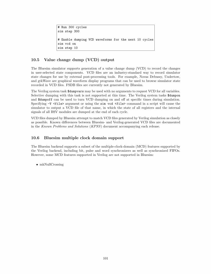
# Run 300 cycles
sim step 300
# Enable dumping VCD waveforms for the next 10 cycles
sim vcd on
sim step 10
10.5 Value change dump (VCD) output
The Bluesim simulator supports generation of a value change dump (VCD) to record the changesin user-selected state components. VCD files are an industry-standard way to record simulatorstate changes for use by external post-processing tools. For example, Novas Debussy, Undertow,and gtkWave are graphical waveform display programs that can be used to browse simulator staterecorded in VCD files. FSDB files are currently not generated by Bluesim.
The Verilog system task $dumpvars may be used with no arguments to request VCD for all variables.Selective dumping with this task is not supported at this time. The Verilog system tasks $dumpon
and $dumpoff can be used to turn VCD dumping on and off at specific times during simulation.Specifying -V <file> argument or using the sim vcd <file> command in a script will cause thesimulator to output a VCD file of that name, in which the state of all registers and the internalsignals of all BSV modules are dumped at the end of each cycle.
VCD files dumped by Bluesim attempt to match VCD files generated by Verilog simulation as closelyas possible. Known differences between Bluesim- and Verilog-generated VCD files are documentedin the Known Problems and Solutions (KPNS ) document accompanying each release.
10.6 Bluesim multiple clock domain support
The Bluesim backend supports a subset of the multiple-clock-domain (MCD) features supported bythe Verilog backend, including bit, pulse and word synchronizers as well as synchronized FIFOs.However, some MCD features supported in Verilog are not supported in Bluesim:
• mkNullCrossing
101
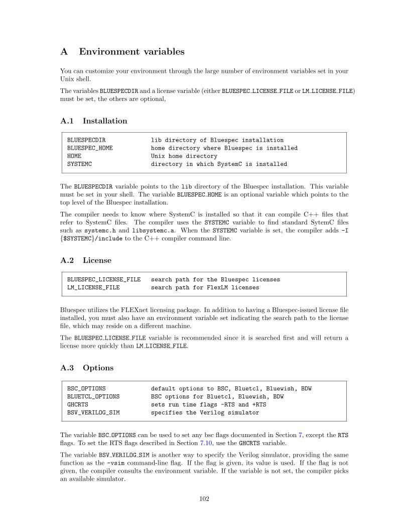
A Environment variables
You can customize your environment through the large number of environment variables set in yourUnix shell.
The variables BLUESPECDIR and a license variable (either BLUESPEC LICENSE FILE or LM LICENSE FILE)must be set, the others are optional,
A.1 Installation
BLUESPECDIR lib directory of Bluespec installation
BLUESPEC_HOME home directory where Bluespec is installed
HOME Unix home directory
SYSTEMC directory in which SystemC is installed
The BLUESPECDIR variable points to the lib directory of the Bluespec installation. This variablemust be set in your shell. The variable BLUESPEC HOME is an optional variable which points to thetop level of the Bluespec installation.
The compiler needs to know where SystemC is installed so that it can compile C++ files thatrefer to SystemC files. The compiler uses the SYSTEMC variable to find standard SytemC filessuch as systemc.h and libsystemc.a. When the SYSTEMC variable is set, the compiler adds -I
{$SYSTEMC}/include to the C++ compiler command line.
A.2 License
BLUESPEC_LICENSE_FILE search path for the Bluespec licenses
LM_LICENSE_FILE search path for FlexLM licenses
Bluespec utilizes the FLEXnet licensing package. In addition to having a Bluespec-issued license fileinstalled, you must also have an environment variable set indicating the search path to the licensefile, which may reside on a different machine.
The BLUESPEC LICENSE FILE variable is recommended since it is searched first and will return alicense more quickly than LM LICENSE FILE.
A.3 Options
BSC_OPTIONS default options to BSC, Bluetcl, Bluewish, BDW
BLUETCL_OPTIONS BSC options for Bluetcl, Bluewish, BDW
GHCRTS sets run time flags -RTS and +RTS
BSV_VERILOG_SIM specifies the Verilog simulator
The variable BSC OPTIONS can be used to set any bsc flags documented in Section 7, except the RTS
flags. To set the RTS flags described in Section 7.10, use the GHCRTS variable.
The variable BSV VERILOG SIM is another way to specify the Verilog simulator, providing the samefunction as the -vsim command-line flag. If the flag is given, its value is used. If the flag is notgiven, the compiler consults the environment variable. If the variable is not set, the compiler picksan available simulator.
102
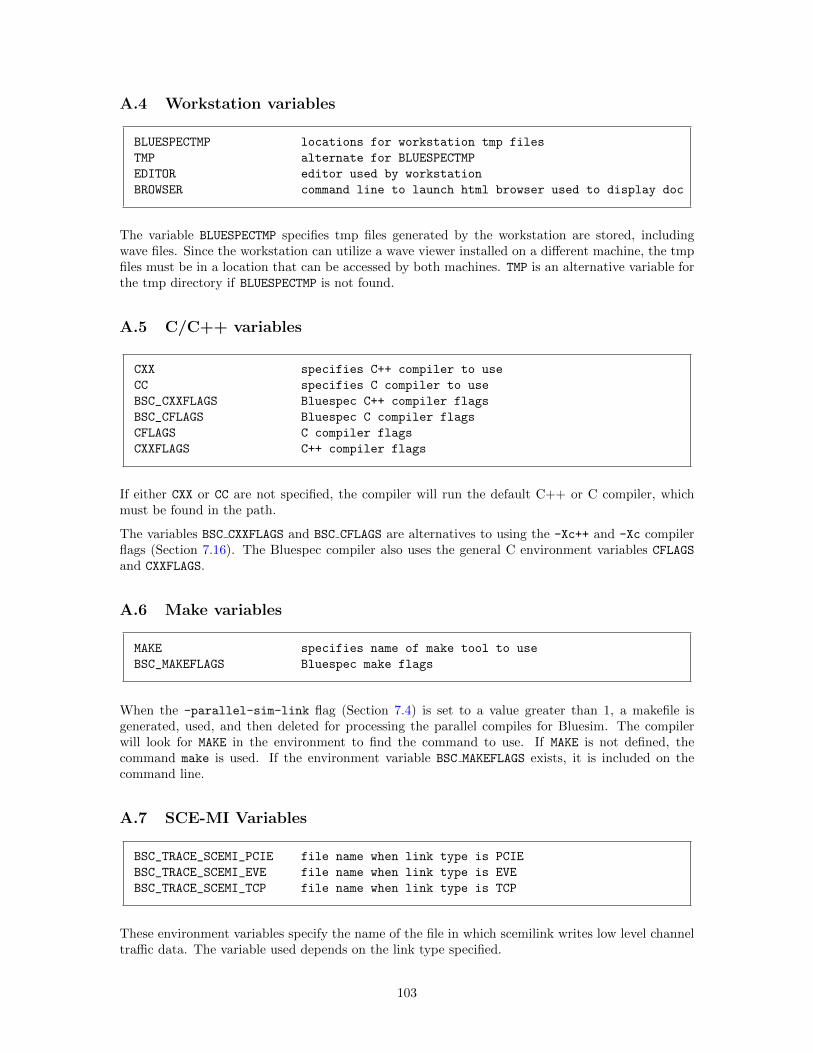
A.4 Workstation variables
BLUESPECTMP locations for workstation tmp files
TMP alternate for BLUESPECTMP
EDITOR editor used by workstation
BROWSER command line to launch html browser used to display doc
The variable BLUESPECTMP specifies tmp files generated by the workstation are stored, includingwave files. Since the workstation can utilize a wave viewer installed on a different machine, the tmpfiles must be in a location that can be accessed by both machines. TMP is an alternative variable forthe tmp directory if BLUESPECTMP is not found.
A.5 C/C++ variables
CXX specifies C++ compiler to use
CC specifies C compiler to use
BSC_CXXFLAGS Bluespec C++ compiler flags
BSC_CFLAGS Bluespec C compiler flags
CFLAGS C compiler flags
CXXFLAGS C++ compiler flags
If either CXX or CC are not specified, the compiler will run the default C++ or C compiler, whichmust be found in the path.
The variables BSC CXXFLAGS and BSC CFLAGS are alternatives to using the -Xc++ and -Xc compilerflags (Section 7.16). The Bluespec compiler also uses the general C environment variables CFLAGS
and CXXFLAGS.
A.6 Make variables
MAKE specifies name of make tool to use
BSC_MAKEFLAGS Bluespec make flags
When the -parallel-sim-link flag (Section 7.4) is set to a value greater than 1, a makefile isgenerated, used, and then deleted for processing the parallel compiles for Bluesim. The compilerwill look for MAKE in the environment to find the command to use. If MAKE is not defined, thecommand make is used. If the environment variable BSC MAKEFLAGS exists, it is included on thecommand line.
A.7 SCE-MI Variables
BSC_TRACE_SCEMI_PCIE file name when link type is PCIE
BSC_TRACE_SCEMI_EVE file name when link type is EVE
BSC_TRACE_SCEMI_TCP file name when link type is TCP
These environment variables specify the name of the file in which scemilink writes low level channeltraffic data. The variable used depends on the link type specified.
103
B Bluetcl Reference
Bluetcl is a Tcl extension with a collection of scripts and packages providing an interface into theBluespec view of a design; Bluewish adds the tk windowing commands to Bluetcl. This documentuses Bluetcl to refer to the combination of Bluetcl and Bluewish. You can execute Bluetcl commandsand scripts from a unix command line or from the command window in the development workstation.
Bluetcl contains several layers (scripts, commands, packages) which should be familiar to the Tclprogrammer. You can use Bluetcl extensions within Tcl scripts. More information on Tcl is availableat www.tcl.tk or from the many books and references written about Tcl/Tk.
B.1 Invoking Bluetcl
Bluetcl commands can be run either interactively or through Tcl scripts. These commands load,execute, and interact with Bluespec-generated files. As with the Bluespec compiler, pre-elaborationinformation is obtained from the .bo files, and post-elaboration information is obtained from the.ba files.
Bluetcl commands can be invoked in the following ways.
• You can invoke Bluetcl from a unix prompt by typing bluetcl. This command provides a Tclshell with the Bluetcl extensions.
• You can type bluewish at a unix prompt. This adds the Wish extensions to the Bluetcl shell.
• When in the Bluespec Development Workstation, the command window provides a Bluetclshell.
• Finally, you can write and use Tcl scripts which utilize Bluetcl. For an example of a Tcl scriptprovided by Bluespec, see Section B.7.1.
B.2 Packages and namespaces
Bluetcl is organized into a collection of packages, which are described in this appendix. The majorpackages are:
• The Bluetcl package which contains the low-level commands to interact with Bluespec filesand designs.
• The Bluesim package containing Bluesim command extensions.3
• The WS package contains commands for interacting with the workstation.
The standard Tcl packages Itcl, Itk, and Iwidgets are available with Bluetcl and can be usedwhen creating your own scripts.
All commands in the Bluetcl package are in the Bluetcl namespace. All commands in the Bluesimpackage are in the Bluesim namespace. The commands in the WS package are divided into multiplenamespaces.
When referencing a command you must specify the namespace. Example:
Bluetcl::version
3The sim command for interacting with Bluesim simulation objects (.so files) is contained in both the Bluetcl
and Bluesim packages.
104
Alternately, you can import commands from a namespace. The following example imports all thecommands in a namespace:
namespace import ::Bluetcl::*
Or you can import a single command:
namespace import ::Bluetcl::schedule
Since the WS package contains multiple namespaces, you must specify the full namespace whenreferencing a WS command or importing the commands from the namespace. Example:
WS::Build::link
namespace import ::WS::Build::link
Refer to the Tcl documentation for additional information on packages and namespaces.
B.3 Customizing Bluetcl
You can use Bluetcl, along with all standard Tcl constructs, to write scripts, issue commands, andcustomize the development workstation. Bluetcl, Bluewish, and the development workstation allsource the setup file $HOME/.bluetclrc during initialization. You can customize Bluetcl and thedevelopment workstation by adding to the .bluetclrc file.
The namespace import command can be put in the .bluetclrc file, providing the command intothe current namespace when the file is sourced. This will allow you to use just the command namein scripts or from the command line.
B.4 General Bluetcl package command reference
B.4.1 Conventions
The following conventions are used within the command reference:
name identifierkeyword as is[...] optional
When an argument (or token) contains embedded spaces, the argument may need to be enclosed inbrackets ({ }).
B.4.2 Bluetcl
This sections describes the commands in the Bluetcl package. These commands provide a low-level interface to access Bluespec-specific files (.bo/.ba) for use by Tcl programmers; they are notintended for interactive use.
Before using a command from the Bluetcl package, the following Tcl command must be executed,either in a script, from the command line, or in the .bluetclrc file:
package require Bluetcl
All commands in the Bluetcl package are in the Bluetcl:: namespace. The namespace mustbe referenced, as described in Section B.3, either by using the namespace import command or byprepending the command name with Bluetcl::. Example:
Bluetcl::bpackage list
105
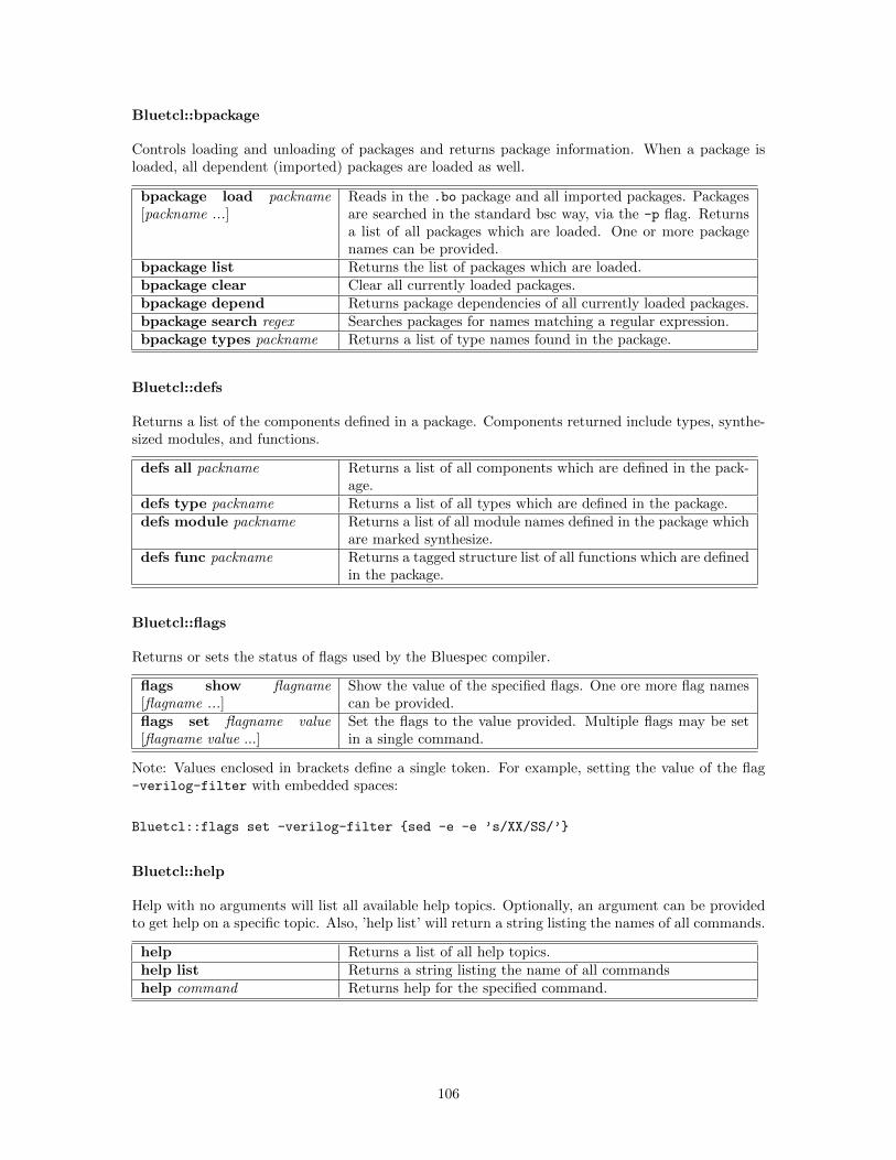
Bluetcl::bpackage
Controls loading and unloading of packages and returns package information. When a package isloaded, all dependent (imported) packages are loaded as well.
bpackage load packname[packname ...]
Reads in the .bo package and all imported packages. Packagesare searched in the standard bsc way, via the -p flag. Returnsa list of all packages which are loaded. One or more packagenames can be provided.
bpackage list Returns the list of packages which are loaded.bpackage clear Clear all currently loaded packages.bpackage depend Returns package dependencies of all currently loaded packages.bpackage search regex Searches packages for names matching a regular expression.bpackage types packname Returns a list of type names found in the package.
Bluetcl::defs
Returns a list of the components defined in a package. Components returned include types, synthe-sized modules, and functions.
defs all packname Returns a list of all components which are defined in the pack-age.
defs type packname Returns a list of all types which are defined in the package.defs module packname Returns a list of all module names defined in the package which
are marked synthesize.defs func packname Returns a tagged structure list of all functions which are defined
in the package.
Bluetcl::flags
Returns or sets the status of flags used by the Bluespec compiler.
flags show flagname[flagname ...]
Show the value of the specified flags. One ore more flag namescan be provided.
flags set flagname value[flagname value ...]
Set the flags to the value provided. Multiple flags may be setin a single command.
Note: Values enclosed in brackets define a single token. For example, setting the value of the flag-verilog-filter with embedded spaces:
Bluetcl::flags set -verilog-filter {sed -e -e ’s/XX/SS/’}
Bluetcl::help
Help with no arguments will list all available help topics. Optionally, an argument can be providedto get help on a specific topic. Also, ’help list’ will return a string listing the names of all commands.
help Returns a list of all help topics.help list Returns a string listing the name of all commandshelp command Returns help for the specified command.
106
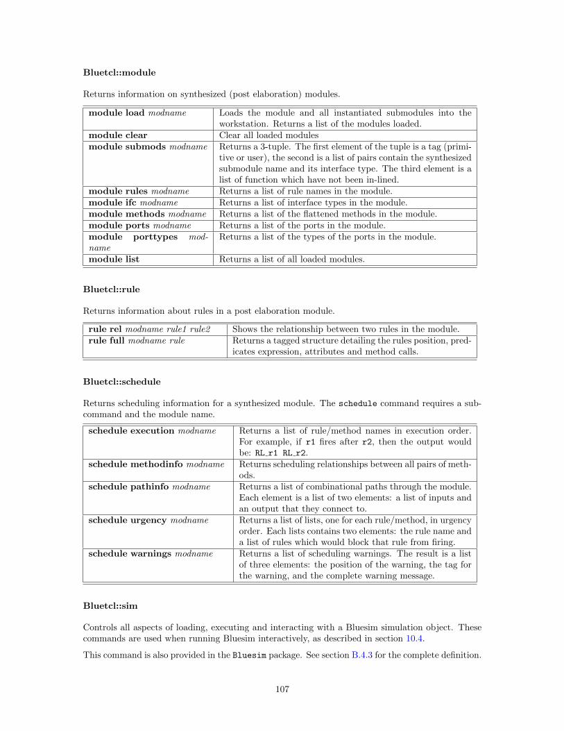
Bluetcl::module
Returns information on synthesized (post elaboration) modules.
module load modname Loads the module and all instantiated submodules into theworkstation. Returns a list of the modules loaded.
module clear Clear all loaded modulesmodule submods modname Returns a 3-tuple. The first element of the tuple is a tag (primi-
tive or user), the second is a list of pairs contain the synthesizedsubmodule name and its interface type. The third element is alist of function which have not been in-lined.
module rules modname Returns a list of rule names in the module.module ifc modname Returns a list of interface types in the module.module methods modname Returns a list of the flattened methods in the module.module ports modname Returns a list of the ports in the module.module porttypes mod-name
Returns a list of the types of the ports in the module.
module list Returns a list of all loaded modules.
Bluetcl::rule
Returns information about rules in a post elaboration module.
rule rel modname rule1 rule2 Shows the relationship between two rules in the module.rule full modname rule Returns a tagged structure detailing the rules position, pred-
icates expression, attributes and method calls.
Bluetcl::schedule
Returns scheduling information for a synthesized module. The schedule command requires a sub-command and the module name.
schedule execution modname Returns a list of rule/method names in execution order.For example, if r1 fires after r2, then the output wouldbe: RL r1 RL r2.
schedule methodinfo modname Returns scheduling relationships between all pairs of meth-ods.
schedule pathinfo modname Returns a list of combinational paths through the module.Each element is a list of two elements: a list of inputs andan output that they connect to.
schedule urgency modname Returns a list of lists, one for each rule/method, in urgencyorder. Each lists contains two elements: the rule name anda list of rules which would block that rule from firing.
schedule warnings modname Returns a list of scheduling warnings. The result is a listof three elements: the position of the warning, the tag forthe warning, and the complete warning message.
Bluetcl::sim
Controls all aspects of loading, executing and interacting with a Bluesim simulation object. Thesecommands are used when running Bluesim interactively, as described in section 10.4.
This command is also provided in the Bluesim package. See section B.4.3 for the complete definition.
107
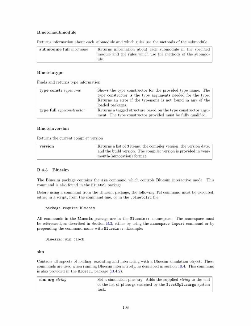
Bluetcl::submodule
Returns information about each submodule and which rules use the methods of the submodule.
submodule full modname Returns information about each submodule in the specifiedmodule and the rules which use the methods of the submod-ule.
Bluetcl::type
Finds and returns type information.
type constr typename Shows the type constructor for the provided type name. Thetype constructor is the type arguments needed for the type.Returns an error if the typename is not found in any of theloaded packages.
type full typeconstructor Returns a tagged structure based on the type constructor argu-ment. The type constructor provided must be fully qualified.
Bluetcl::version
Returns the current compiler version
version Returns a list of 3 items: the compiler version, the version date,and the build version. The compiler version is provided in year-month-(annotation) format.
B.4.3 Bluesim
The Bluesim package contains the sim command which controls Bluesim interactive mode. Thiscommand is also found in the Bluetcl package.
Before using a command from the Bluesim package, the following Tcl command must be executed,either in a script, from the command line, or in the .bluetclrc file:
package require Bluesim
All commands in the Bluesim package are in the Bluesim:: namespace. The namespace mustbe referenced, as described in Section B.3, either by using the namespace import command or byprepending the command name with Bluesim::. Example:
Bluesim::sim clock
sim
Controls all aspects of loading, executing and interacting with a Bluesim simulation object. Thesecommands are used when running Bluesim interactively, as described in section 10.4. This commandis also provided in the Bluetcl package (B.4.2).
sim arg string Set a simulation plus-arg. Adds the supplied string to the endof the list of plusargs searched by the $test$plusargs systemtask.
108
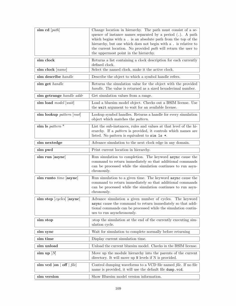
sim cd [path] Change location in hierarchy. The path must consist of a se-quence of instance names separated by a period (.). A pathwhich begins with a . is an absolute path from the top of thehierarchy, but one which does not begin with a . is relative tothe current location. No provided path will return the user tothe uppermost point in the hierarchy.
sim clock Returns a list containing a clock description for each currentlydefined clock.
sim clock [name] Select the named clock, make it the active clock.
sim describe handle Describe the object to which a symbol handle refers.
sim get handle Returns the simulation value for the object with the providedhandle. The value is returned as a sized hexadecimal number.
sim getrange handle addr Get simulation values from a range.
sim load model [wait] Load a bluesim model object. Checks out a BSIM license. Usethe wait argument to wait for an available license.
sim lookup pattern [root] Lookup symbol handles. Returns a handle for every simulationobject which matches the pattern.
sim ls pattern * List the sub-instances, rules and values at that level of the hi-erarchy. If a pattern is provided, it controls which names arelisted. No pattern is equivalent to sim ls *.
sim nextedge Advance simulation to the next clock edge in any domain.
sim pwd Print current location in hierarchy.
sim run [async] Run simulation to completion. The keyword async cause thecommand to return immediately so that additional commandscan be processed while the simulation continues to run asyn-chronously.
sim runto time [async] Run simulation to a given time. The keyword async cause thecommand to return immediately so that additional commandscan be processed while the simulation continues to run asyn-chronously.
sim step [cycles] [async] Advance simulation a given number of cycles. The keywordasync cause the command to return immediately so that addi-tional commands can be processed while the simulation contin-ues to run asynchronously.
sim stop :stop the simulation at the end of the currently executing sim-ulation cycle.
sim sync Wait for simulation to complete normally before returning
sim time Display current simulation time.
sim unload Unload the current bluesim model. Checks in the BSIM license.
sim up [N] Move up the module hierarchy into the parents of the currentdirectory. It will move up N levels if N is provided.
sim vcd [on | off | file] Control dumping waveforms to a VCD file named file. If no filename is provided, it will use the default file dump.vcd.
sim version Show Bluesim model version information.
109
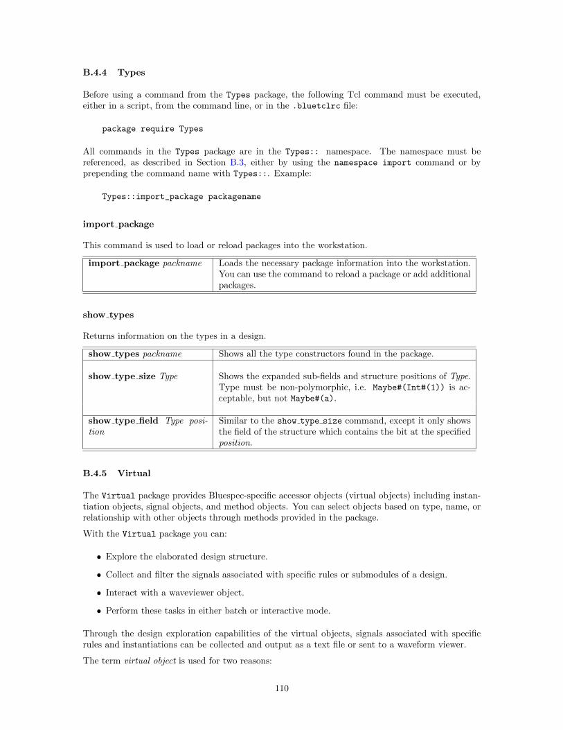
B.4.4 Types
Before using a command from the Types package, the following Tcl command must be executed,either in a script, from the command line, or in the .bluetclrc file:
package require Types
All commands in the Types package are in the Types:: namespace. The namespace must bereferenced, as described in Section B.3, either by using the namespace import command or byprepending the command name with Types::. Example:
Types::import_package packagename
import package
This command is used to load or reload packages into the workstation.
import package packname Loads the necessary package information into the workstation.You can use the command to reload a package or add additionalpackages.
show types
Returns information on the types in a design.
show types packname Shows all the type constructors found in the package.
show type size Type Shows the expanded sub-fields and structure positions of Type.Type must be non-polymorphic, i.e. Maybe#(Int#(1)) is ac-ceptable, but not Maybe#(a).
show type field Type posi-tion
Similar to the show type size command, except it only showsthe field of the structure which contains the bit at the specifiedposition.
B.4.5 Virtual
The Virtual package provides Bluespec-specific accessor objects (virtual objects) including instan-tiation objects, signal objects, and method objects. You can select objects based on type, name, orrelationship with other objects through methods provided in the package.
With the Virtual package you can:
• Explore the elaborated design structure.
• Collect and filter the signals associated with specific rules or submodules of a design.
• Interact with a waveviewer object.
• Perform these tasks in either batch or interactive mode.
Through the design exploration capabilities of the virtual objects, signals associated with specificrules and instantiations can be collected and output as a text file or sent to a waveform viewer.
The term virtual object is used for two reasons:
110
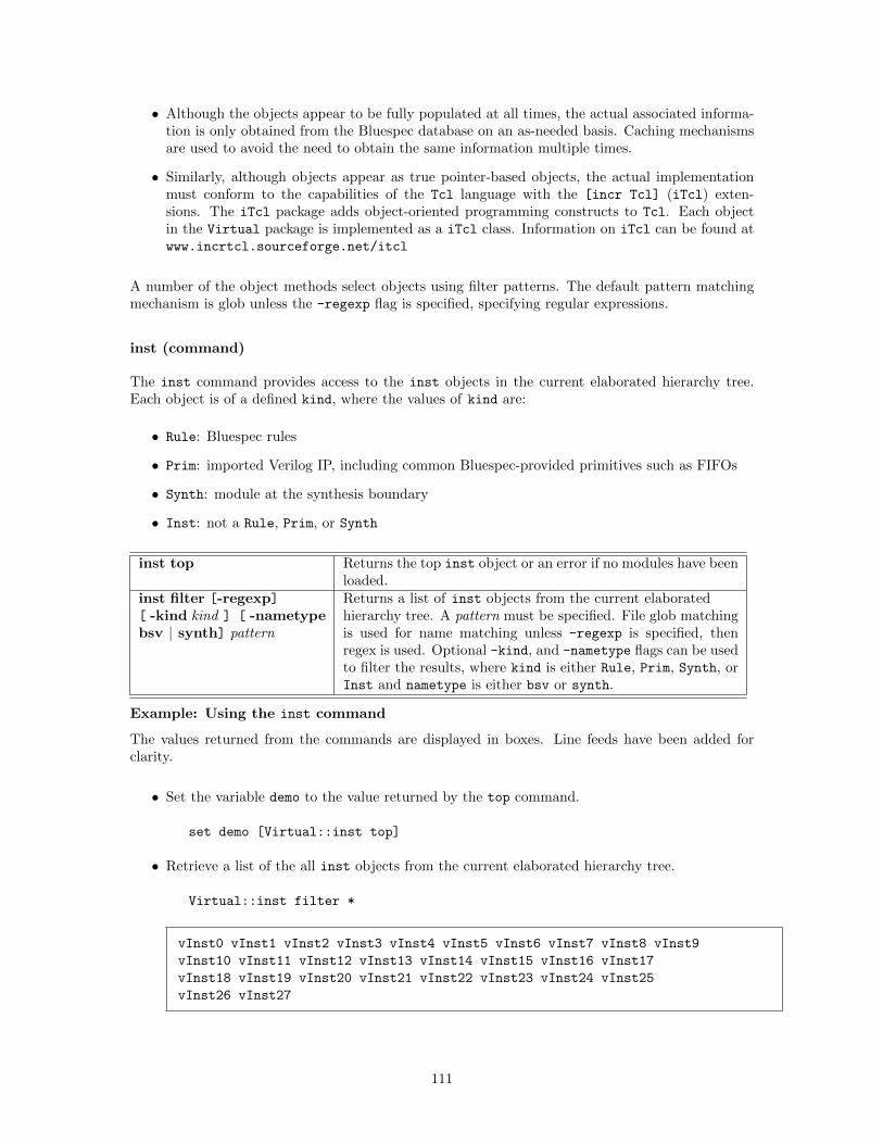
• Although the objects appear to be fully populated at all times, the actual associated informa-tion is only obtained from the Bluespec database on an as-needed basis. Caching mechanismsare used to avoid the need to obtain the same information multiple times.
• Similarly, although objects appear as true pointer-based objects, the actual implementationmust conform to the capabilities of the Tcl language with the [incr Tcl] (iTcl) exten-sions. The iTcl package adds object-oriented programming constructs to Tcl. Each objectin the Virtual package is implemented as a iTcl class. Information on iTcl can be found atwww.incrtcl.sourceforge.net/itcl
A number of the object methods select objects using filter patterns. The default pattern matchingmechanism is glob unless the -regexp flag is specified, specifying regular expressions.
inst (command)
The inst command provides access to the inst objects in the current elaborated hierarchy tree.Each object is of a defined kind, where the values of kind are:
• Rule: Bluespec rules
• Prim: imported Verilog IP, including common Bluespec-provided primitives such as FIFOs
• Synth: module at the synthesis boundary
• Inst: not a Rule, Prim, or Synth
inst top Returns the top inst object or an error if no modules have beenloaded.
inst filter [-regexp] Returns a list of inst objects from the current elaborated[ -kind kind ] [ -nametypebsv | synth] pattern
hierarchy tree. A pattern must be specified. File glob matchingis used for name matching unless -regexp is specified, thenregex is used. Optional -kind, and -nametype flags can be usedto filter the results, where kind is either Rule, Prim, Synth, orInst and nametype is either bsv or synth.
Example: Using the inst command
The values returned from the commands are displayed in boxes. Line feeds have been added forclarity.
• Set the variable demo to the value returned by the top command.
set demo [Virtual::inst top]
• Retrieve a list of the all inst objects from the current elaborated hierarchy tree.
Virtual::inst filter *
vInst0 vInst1 vInst2 vInst3 vInst4 vInst5 vInst6 vInst7 vInst8 vInst9
vInst10 vInst11 vInst12 vInst13 vInst14 vInst15 vInst16 vInst17
vInst18 vInst19 vInst20 vInst21 vInst22 vInst23 vInst24 vInst25
vInst26 vInst27
111
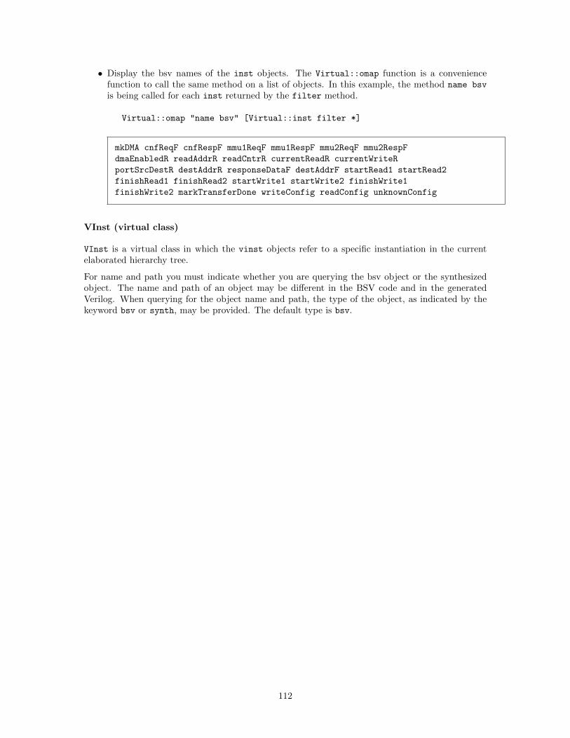
• Display the bsv names of the inst objects. The Virtual::omap function is a conveniencefunction to call the same method on a list of objects. In this example, the method name bsv
is being called for each inst returned by the filter method.
Virtual::omap "name bsv" [Virtual::inst filter *]
mkDMA cnfReqF cnfRespF mmu1ReqF mmu1RespF mmu2ReqF mmu2RespF
dmaEnabledR readAddrR readCntrR currentReadR currentWriteR
portSrcDestR destAddrR responseDataF destAddrF startRead1 startRead2
finishRead1 finishRead2 startWrite1 startWrite2 finishWrite1
finishWrite2 markTransferDone writeConfig readConfig unknownConfig
VInst (virtual class)
VInst is a virtual class in which the vinst objects refer to a specific instantiation in the currentelaborated hierarchy tree.
For name and path you must indicate whether you are querying the bsv object or the synthesizedobject. The name and path of an object may be different in the BSV code and in the generatedVerilog. When querying for the object name and path, the type of the object, as indicated by thekeyword bsv or synth, may be provided. The default type is bsv.
112
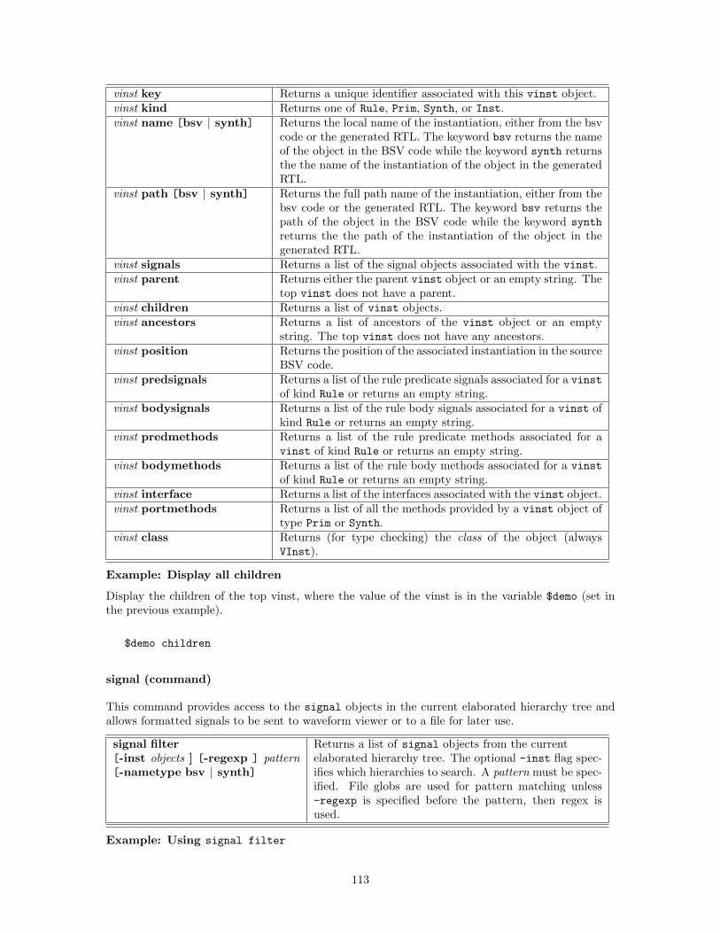
vinst key Returns a unique identifier associated with this vinst object.vinst kind Returns one of Rule, Prim, Synth, or Inst.vinst name [bsv | synth] Returns the local name of the instantiation, either from the bsv
code or the generated RTL. The keyword bsv returns the nameof the object in the BSV code while the keyword synth returnsthe the name of the instantiation of the object in the generatedRTL.
vinst path [bsv | synth] Returns the full path name of the instantiation, either from thebsv code or the generated RTL. The keyword bsv returns thepath of the object in the BSV code while the keyword synth
returns the the path of the instantiation of the object in thegenerated RTL.
vinst signals Returns a list of the signal objects associated with the vinst.vinst parent Returns either the parent vinst object or an empty string. The
top vinst does not have a parent.vinst children Returns a list of vinst objects.vinst ancestors Returns a list of ancestors of the vinst object or an empty
string. The top vinst does not have any ancestors.vinst position Returns the position of the associated instantiation in the source
BSV code.vinst predsignals Returns a list of the rule predicate signals associated for a vinst
of kind Rule or returns an empty string.vinst bodysignals Returns a list of the rule body signals associated for a vinst of
kind Rule or returns an empty string.vinst predmethods Returns a list of the rule predicate methods associated for a
vinst of kind Rule or returns an empty string.vinst bodymethods Returns a list of the rule body methods associated for a vinst
of kind Rule or returns an empty string.vinst interface Returns a list of the interfaces associated with the vinst object.vinst portmethods Returns a list of all the methods provided by a vinst object of
type Prim or Synth.vinst class Returns (for type checking) the class of the object (always
VInst).
Example: Display all children
Display the children of the top vinst, where the value of the vinst is in the variable $demo (set inthe previous example).
$demo children
signal (command)
This command provides access to the signal objects in the current elaborated hierarchy tree andallows formatted signals to be sent to waveform viewer or to a file for later use.
signal filter Returns a list of signal objects from the current[-inst objects ] [-regexp ] pattern[-nametype bsv | synth]
elaborated hierarchy tree. The optional -inst flag spec-ifies which hierarchies to search. A pattern must be spec-ified. File globs are used for pattern matching unless-regexp is specified before the pattern, then regex isused.
Example: Using signal filter
113
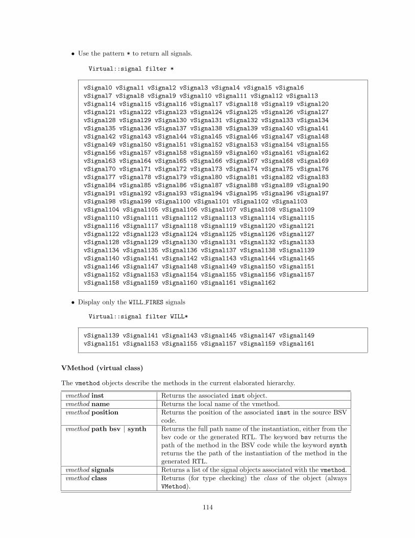
• Use the pattern * to return all signals.
Virtual::signal filter *
vSignal0 vSignal1 vSignal2 vSignal3 vSignal4 vSignal5 vSignal6
vSignal7 vSignal8 vSignal9 vSignal10 vSignal11 vSignal12 vSignal13
vSignal14 vSignal15 vSignal16 vSignal17 vSignal18 vSignal19 vSignal20
vSignal21 vSignal22 vSignal23 vSignal24 vSignal25 vSignal26 vSignal27
vSignal28 vSignal29 vSignal30 vSignal31 vSignal32 vSignal33 vSignal34
vSignal35 vSignal36 vSignal37 vSignal38 vSignal39 vSignal40 vSignal41
vSignal42 vSignal43 vSignal44 vSignal45 vSignal46 vSignal47 vSignal48
vSignal49 vSignal50 vSignal51 vSignal52 vSignal53 vSignal54 vSignal55
vSignal56 vSignal57 vSignal58 vSignal59 vSignal60 vSignal61 vSignal62
vSignal63 vSignal64 vSignal65 vSignal66 vSignal67 vSignal68 vSignal69
vSignal70 vSignal71 vSignal72 vSignal73 vSignal74 vSignal75 vSignal76
vSignal77 vSignal78 vSignal79 vSignal80 vSignal81 vSignal82 vSignal83
vSignal84 vSignal85 vSignal86 vSignal87 vSignal88 vSignal89 vSignal90
vSignal91 vSignal92 vSignal93 vSignal94 vSignal95 vSignal96 vSignal97
vSignal98 vSignal99 vSignal100 vSignal101 vSignal102 vSignal103
vSignal104 vSignal105 vSignal106 vSignal107 vSignal108 vSignal109
vSignal110 vSignal111 vSignal112 vSignal113 vSignal114 vSignal115
vSignal116 vSignal117 vSignal118 vSignal119 vSignal120 vSignal121
vSignal122 vSignal123 vSignal124 vSignal125 vSignal126 vSignal127
vSignal128 vSignal129 vSignal130 vSignal131 vSignal132 vSignal133
vSignal134 vSignal135 vSignal136 vSignal137 vSignal138 vSignal139
vSignal140 vSignal141 vSignal142 vSignal143 vSignal144 vSignal145
vSignal146 vSignal147 vSignal148 vSignal149 vSignal150 vSignal151
vSignal152 vSignal153 vSignal154 vSignal155 vSignal156 vSignal157
vSignal158 vSignal159 vSignal160 vSignal161 vSignal162
• Display only the WILL FIRES signals
Virtual::signal filter WILL*
vSignal139 vSignal141 vSignal143 vSignal145 vSignal147 vSignal149
vSignal151 vSignal153 vSignal155 vSignal157 vSignal159 vSignal161
VMethod (virtual class)
The vmethod objects describe the methods in the current elaborated hierarchy.
vmethod inst Returns the associated inst object.vmethod name Returns the local name of the vmethod.vmethod position Returns the position of the associated inst in the source BSV
code.vmethod path bsv | synth Returns the full path name of the instantiation, either from the
bsv code or the generated RTL. The keyword bsv returns thepath of the method in the BSV code while the keyword synth
returns the the path of the instantiation of the method in thegenerated RTL.
vmethod signals Returns a list of the signal objects associated with the vmethod.vmethod class Returns (for type checking) the class of the object (always
VMethod).
114
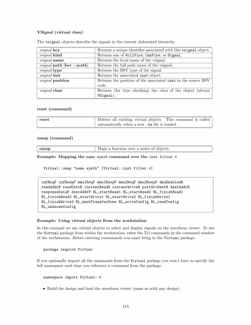
VSignal (virtual class)
The vsignal objects describe the signals in the current elaborated hierarchy.
vsignal key Returns a unique identifier associated with this vsignal object.vsignal kind Returns one of WillFire, CanFire, or Signal.vsignal name Returns the local name of the vsignal.vsignal path [bsv | synth] Returns the full path name of the vsignal.vsignal type Returns the BSV type of the signal.vsignal inst Returns the associated inst object.vsignal position Returns the position of the associated inst in the source BSV
code.vsignal class Returns (for type checking) the class of the object (always
VSignal).
reset (command)
reset Deletes all existing virtual objects. This command is calledautomatically when a new .ba file is loaded.
omap (command)
omap Maps a function over a series of objects.
Example: Mapping the name synth command over the inst filter *
Virtual::omap "name synth" [Virtual::inst filter *]
cnfReqF cnfRespF mmu1ReqF mmu1RespF mmu2ReqF mmu2RespF dmaEnabledR
readAddrR readCntrR currentReadR currentWriteR portSrcDestR destAddrR
responseDataF destAddrF RL_startRead1 RL_startRead2 RL_finishRead1
RL_finishRead2 RL_startWrite1 RL_startWrite2 RL_finishWrite1
RL_finishWrite2 RL_markTransferDone RL_writeConfig RL_readConfig
RL_unknownConfig
Example: Using virtual objects from the workstation
In this example we use virtual objects to select and display signals on the waveform viewer. To usethe Virtual package from within the workstation, enter the Tcl commands in the command windowof the workstation. Before entering commannds you must bring in the Virtual package:
package require Virtual
If you optionally import all the commands from the Virtual package you won’t have to specify thefull namespace each time you reference a command from the package:
namespace import Virtual::*
• Build the design and load the waveform viewer (same as with any design)
115
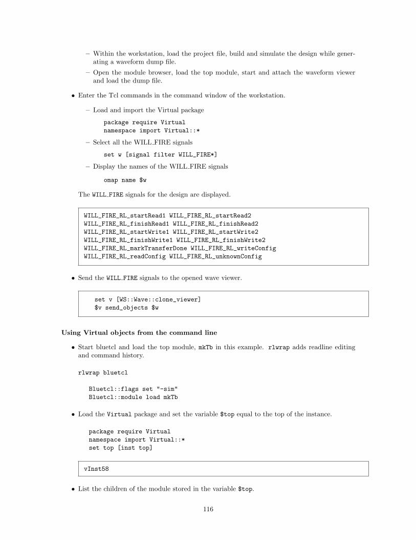
– Within the workstation, load the project file, build and simulate the design while gener-ating a waveform dump file.
– Open the module browser, load the top module, start and attach the waveform viewerand load the dump file.
• Enter the Tcl commands in the command window of the workstation.
– Load and import the Virtual package
package require Virtual
namespace import Virtual::*
– Select all the WILL FIRE signals
set w [signal filter WILL_FIRE*]
– Display the names of the WILL FIRE signals
omap name $w
The WILL FIRE signals for the design are displayed.
WILL_FIRE_RL_startRead1 WILL_FIRE_RL_startRead2
WILL_FIRE_RL_finishRead1 WILL_FIRE_RL_finishRead2
WILL_FIRE_RL_startWrite1 WILL_FIRE_RL_startWrite2
WILL_FIRE_RL_finishWrite1 WILL_FIRE_RL_finishWrite2
WILL_FIRE_RL_markTransferDone WILL_FIRE_RL_writeConfig
WILL_FIRE_RL_readConfig WILL_FIRE_RL_unknownConfig
• Send the WILL FIRE signals to the opened wave viewer.
set v [WS::Wave::clone_viewer]
$v send_objects $w
Using Virtual objects from the command line
• Start bluetcl and load the top module, mkTb in this example. rlwrap adds readline editingand command history.
rlwrap bluetcl
Bluetcl::flags set "-sim"
Bluetcl::module load mkTb
• Load the Virtual package and set the variable $top equal to the top of the instance.
package require Virtual
namespace import Virtual::*
set top [inst top]
vInst58
• List the children of the module stored in the variable $top.
116
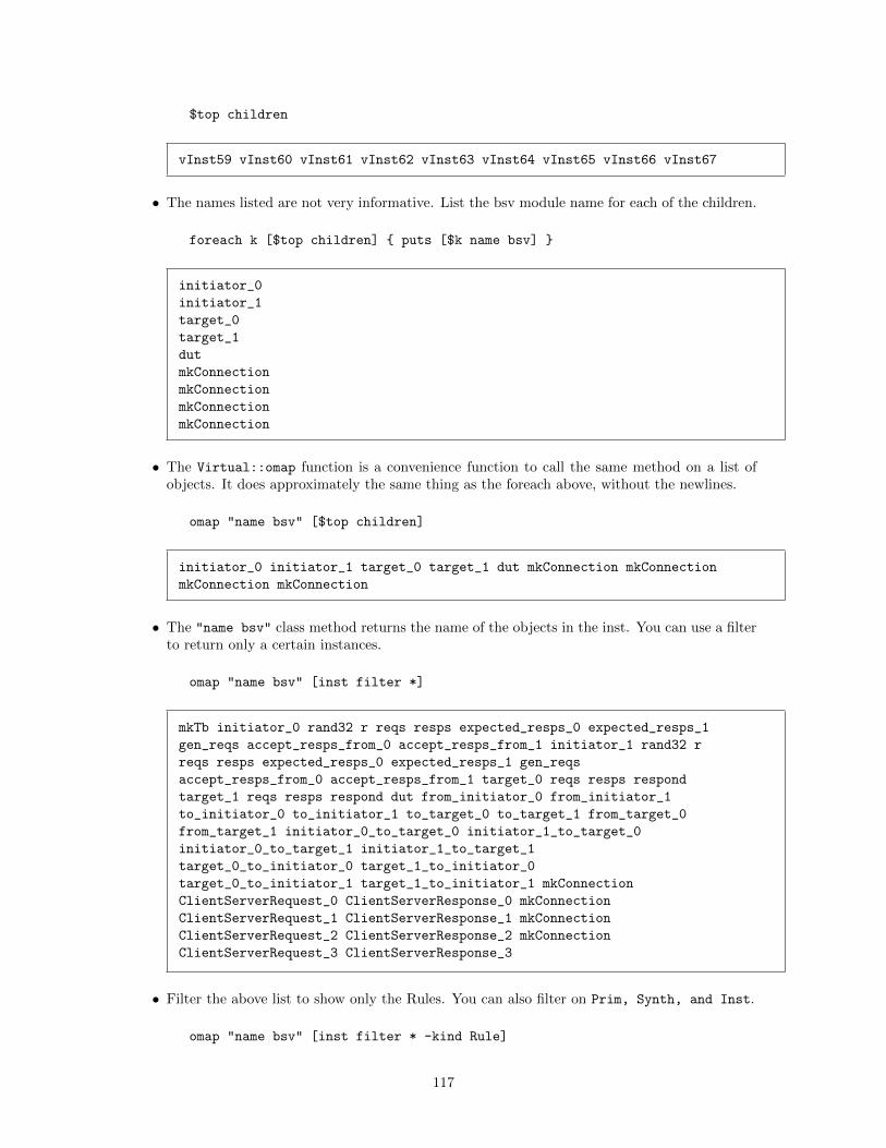
$top children
vInst59 vInst60 vInst61 vInst62 vInst63 vInst64 vInst65 vInst66 vInst67
• The names listed are not very informative. List the bsv module name for each of the children.
foreach k [$top children] { puts [$k name bsv] }
initiator_0
initiator_1
target_0
target_1
dut
mkConnection
mkConnection
mkConnection
mkConnection
• The Virtual::omap function is a convenience function to call the same method on a list ofobjects. It does approximately the same thing as the foreach above, without the newlines.
omap "name bsv" [$top children]
initiator_0 initiator_1 target_0 target_1 dut mkConnection mkConnection
mkConnection mkConnection
• The "name bsv" class method returns the name of the objects in the inst. You can use a filterto return only a certain instances.
omap "name bsv" [inst filter *]
mkTb initiator_0 rand32 r reqs resps expected_resps_0 expected_resps_1
gen_reqs accept_resps_from_0 accept_resps_from_1 initiator_1 rand32 r
reqs resps expected_resps_0 expected_resps_1 gen_reqs
accept_resps_from_0 accept_resps_from_1 target_0 reqs resps respond
target_1 reqs resps respond dut from_initiator_0 from_initiator_1
to_initiator_0 to_initiator_1 to_target_0 to_target_1 from_target_0
from_target_1 initiator_0_to_target_0 initiator_1_to_target_0
initiator_0_to_target_1 initiator_1_to_target_1
target_0_to_initiator_0 target_1_to_initiator_0
target_0_to_initiator_1 target_1_to_initiator_1 mkConnection
ClientServerRequest_0 ClientServerResponse_0 mkConnection
ClientServerRequest_1 ClientServerResponse_1 mkConnection
ClientServerRequest_2 ClientServerResponse_2 mkConnection
ClientServerRequest_3 ClientServerResponse_3
• Filter the above list to show only the Rules. You can also filter on Prim, Synth, and Inst.
omap "name bsv" [inst filter * -kind Rule]
117
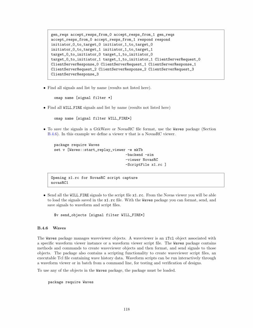
gen_reqs accept_resps_from_0 accept_resps_from_1 gen_reqs
accept_resps_from_0 accept_resps_from_1 respond respond
initiator_0_to_target_0 initiator_1_to_target_0
initiator_0_to_target_1 initiator_1_to_target_1
target_0_to_initiator_0 target_1_to_initiator_0
target_0_to_initiator_1 target_1_to_initiator_1 ClientServerRequest_0
ClientServerResponse_0 ClientServerRequest_1 ClientServerResponse_1
ClientServerRequest_2 ClientServerResponse_2 ClientServerRequest_3
ClientServerResponse_3
• Find all signals and list by name (results not listed here).
omap name [signal filter *]
• Find all WILL FIRE signals and list by name (results not listed here)
omap name [signal filter WILL_FIRE*]
• To save the signals in a GtkWave or NovasRC file format, use the Waves package (SectionB.4.6). In this example we define a viewer v that is a NovasRC viewer.
package require Waves
set v [Waves::start_replay_viewer -e mkTb
-backend -sim
-viewer NovasRC
-ScriptFile x1.rc ]
Opening x1.rc for NovasRC script capture
novasRC1
• Send all the WILL FIRE signals to the script file x1.rc. From the Novas viewer you will be ableto load the signals saved in the x1.rc file. With the Waves package you can format, send, andsave signals to waveform and script files.
$v send_objects [signal filter WILL_FIRE*]
B.4.6 Waves
The Waves package manages waveviewer objects. A waveviewer is an iTcl object associated witha specific waveform viewer instance or a waveform viewer script file. The Waves package containsmethods and commands to create waveviewer objects and then format, and send signals to thoseobjects. The package also contains a scripting functionality to create waveviewer script files, anexecutable Tcl file containing wave history data. Waveform scripts can be run interactively througha waveform viewer or in batch from a command line, for testing and verification of designs.
To use any of the objects in the Waves package, the package must be loaded.
package require Waves
118
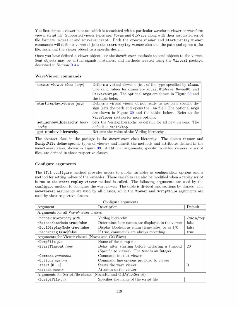
You first define a viewer instance which is associated with a particular waveform viewer or waveformviewer script file. Supported viewer types are: Novas and GtkWave along with their associated scriptfile formats: NovasRC and GtkWaveScript. Both the create viewer and start replay viewer
commands will define a viewer object; the start replay viewer also sets the path and opens a .ba
file, assigning the viewer object to a specific design.
Once you have defined a viewer object, use the WaveViewer methods to send objects to the viewer.Sent objects may be virtual signals, instances, and methods created using the Virtual package,described in Section B.4.5.
WaveViewer commands
create viewer class [args] Defines a virtual viewer object of the type specified by class.The valid values for class are Novas, GtkWave, NovasRC, andGtkWaveSript. The optional args are shown in Figure 39 andthe table below.
start replay viewer [args] Defines a virtual viewer object ready to use on a specific de-sign (sets the path and opens the .ba file.) The optional argsare shown in Figure 39 and the tables below. Refer to theWaveViewer section for more options.
set nonbsv hierarchy hier-archy
Sets the Verilog hierarchy as default for all new viewers. Thedefault is /main/top.
get nonbsv hierarchy Returns the value of the Verilog hierarchy.
The abstract class in the package is the WaveViewer class hierarchy. The classes Viewer andScriptFile define specific types of viewers and inherit the methods and attributes defined in theWaveViewer class, shown in Figure 39. Additional arguments, specific to either viewers or scriptfiles, are defined in those respective classes.
Configure arguments
The iTcl configure method provides access to public variables as configuration options and amethod for setting values of the variables. These variables can also be modified when a replay scriptis run or the start replay viewer method is called. The following arguments are used by theconfigure method to configure the waveviewer. The table is divided into sections by classes. TheWaveViewer arguments are used by all classes, while the Viewer and ScriptFile arguments areused by their respective classes.
Configure argumentsArgument Description Default
Arguments for all WaveViewer classes
-nonbsv hierarchy path Verilog hierarchy /main/top
-ExtendNameMode true|false Determines how names are displayed in the viewer false-BoolDisplayMode true|false Display Boolean as enum (true/false) or as 1/0 false-recording true|false If true, commands are always recording trueArguments for Viewer classes (Novas and GtkWave)-DumpFile file Name of the dump file-StartTimeout time Delay after starting before declaring a timeout
(Specific to viewer). The time is an Integer.20
-Command command Command to start viewer-Options options Command line options provided to viewer-start [0 | 1] Starts the wave viewer 0-attach viewer Attaches to the viewerArguments for ScriptFile classes (NovasRc and GtkWaveScript)-ScriptFile file Specifies the name of the script file.
119
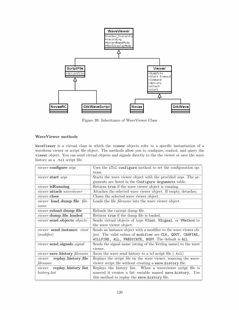
Figure 39: Inheritance of WaveViewer Class
WaveViewer methods
WaveViewer is a virtual class in which the viewer objects refer to a specific instantiation of awaveform viewer or script file object. The methods allow you to configure, control, and query theviewer object. You can send virtual objects and signals directly to the the viewer or save the wavehistory as a .tcl script file.
viewer configure args Uses the iTcl configure method to set the configuration op-tions.
viewer start args Starts the wave viewer object with the provided args. The ar-guments are listed in the Configure Arguments table.
viewer isRunning Returns true if the wave viewer object is running.viewer attach waveviewer Attaches the selected wave viewer object. If empty, detaches.viewer close Closes the selected wave viewer object.viewer load dump file file-name
Loads the file filename into the wave viewer object.
viewer reload dump file Reloads the current dump file.viewer dump file loaded Returns true if the dump file is loaded.viewer send objects objects Sends virtual objects of type VInst, VSignal, or VMethod to
the wave viewer object.viewer send instance vinst[modifier]
Sends an instance object with a modifier to the wave viewer ob-ject. The valid values of modifier are CLK, QOUT, CANFIRE,
WILLFIRE, ALL, PREDICATE, BODY. The default is ALL.viewer send signals signal Sends the signal name (string of the Verilog name) to the wave
viewer.viewer save history filename Saves the wave send history to a tcl script file (.tcl)viewer replay history filefilename
Replays the script file on the wave viewer, sourcing the wave-viewer script file without creating a wave history file.
viewer replay history listhistory list
Replays the history list. When a waveviewer script file issourced it creates a list variable named wave history. Usethis method to replay the wave history file.
120
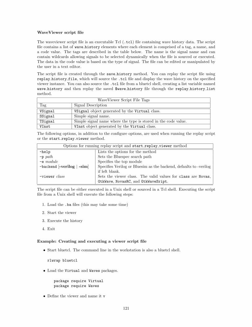
WaveViewer script file
The waveviewer script file is an executable Tcl (.tcl) file containing wave history data. The scriptfile contains a list of wave history elements where each element is comprised of a tag, a name, anda code value. The tags are described in the table below. The name is the signal name and cancontain wildcards allowing signals to be selected dynamically when the file is sourced or executed.The data in the code value is based on the type of signal. The file can be edited or manipulated bythe user in a text editor.
The script file is created through the save history method. You can replay the script file usingreplay history file, which will source the .tcl file and display the wave history on the specifiedviewer instance. You can also source the .tcl file from a bluetcl shell, creating a list variable namedwave history and then replay the saved $wave history file through the replay history list
method.
WaveViewer Script File TagsTag Signal Description
VSignal VSignal object generated by the Virtual class.SSignal Simple signal name.TSignal Simple signal name where the type is stored in the code value.VInst VInst object generated by the Virtual class.
The following options, in addition to the configure options, are used when running the replay scriptor the start replay viewer method.
Options for running replay script and start replay viewer method
-help Lists the options for the method-p path Sets the Bluespec search path-e module Specifies the top module-backend [-verilog | -sim] Specifies Verilog or Bluesim as the backend, defaults to -verilog
if left blank.-viewer class Sets the viewer class. The valid values for class are Novas,
GtkWave, NovasRC, and GtkWaveSript.
The script file can be either executed in a Unix shell or sourced in a Tcl shell. Executing the scriptfile from a Unix shell will execute the following steps:
1. Load the .ba files (this may take some time)
2. Start the viewer
3. Execute the history
4. Exit
Example: Creating and executing a viewer script file
• Start bluetcl. The command line in the workstation is also a bluetcl shell.
rlwrap bluetcl
• Load the Virtual and Waves packages.
package require Virtual
package require Waves
• Define the viewer and name it v
121
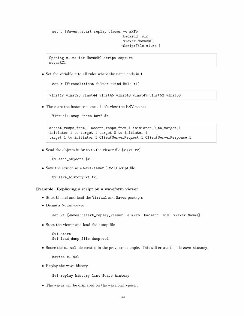
set v [Waves::start_replay_viewer -e mkTb
-backend -sim
-viewer NovasRC
-ScriptFile x1.rc ]
Opening x1.rc for NovasRC script capture
novasRC1
• Set the variable r to all rules where the name ends in 1
set r [Virtual::inst filter -kind Rule *1]
vInst17 vInst26 vInst44 vInst45 vInst48 vInst49 vInst52 vInst53
• These are the instance names. Let’s view the BSV names
Virtual::omap "name bsv" $r
accept_resps_from_1 accept_resps_from_1 initiator_0_to_target_1
initiator_1_to_target_1 target_0_to_initiator_1
target_1_to_initiator_1 ClientServerRequest_1 ClientServerResponse_1
• Send the objects in $r to to the viewer file $v (x1.rc)
$v send_objects $r
• Save the session as a WaveViewer (.tcl) script file
$v save_history x1.tcl
Example: Replaying a script on a waveform viewer
• Start bluetcl and load the Virtual and Waves packages
• Define a Novas viewer
set v1 [Waves::start_replay_viewer -e mkTb -backend -sim -viewer Novas]
• Start the viewer and load the dump file
$v1 start
$v1 load_dump_file dump.vcd
• Souce the x1.tcl file created in the previous example. This will create the file wave history.
source x1.tcl
• Replay the wave history
$v1 replay_history_list $wave_history
• The waves will be displayed on the waveform viewer.
122
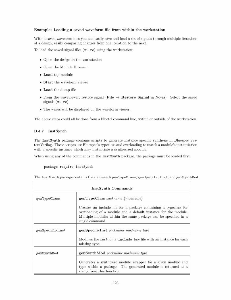
Example: Loading a saved waveform file from within the workstation
With a saved waveform files you can easily save and load a set of signals through multiple iterationsof a design, easily comparing changes from one iteration to the next.
To load the saved signal files (x1.rc) using the workstation:
• Open the design in the workstation
• Open the Module Browser
• Load top module
• Start the waveform viewer
• Load the dump file
• From the waveviewer, restore signal (File → Restore Signal in Novas). Select the savedsignals (x1.rc).
• The waves will be displayed on the waveform viewer.
The above steps could all be done from a bluetcl command line, within or outside of the workstation.
B.4.7 InstSynth
The InstSynth package contains scripts to generate instance specific synthesis in Bluespec Sys-temVerilog. These scripts use Bluespec’s typeclass and overloading to match a module’s instantiationwith a specific instance which may instantiate a synthesized module.
When using any of the commands in the InstSynth package, the package must be loaded first.
package require InstSynth
The InstSynth package contains the commands genTypeClass, genSpecificInst, and genSynthMod.
InstSynth Commands
genTypeClass genTypeClass packname {modname}
Creates an include file for a package containing a typeclass foroverloading of a module and a default instance for the module.Multiple modules within the same package can be specified in asingle command.
genSpecificInst genSpecificInst packname modname type
Modifies the packname.include.bsv file with an instance for eachmissing type.
genSynthMod genSynthMod packname modname type
Generates a synthesize module wrapper for a given module andtype within a package. The generated module is returned as astring from this function.
123
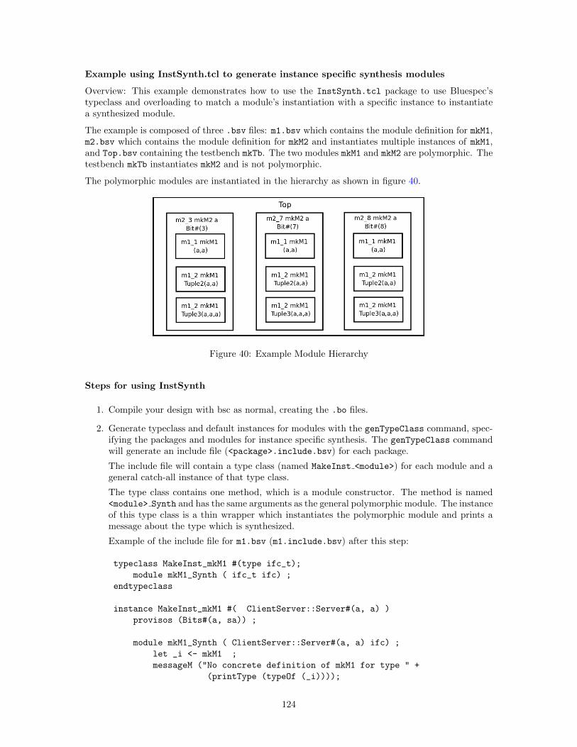
Example using InstSynth.tcl to generate instance specific synthesis modules
Overview: This example demonstrates how to use the InstSynth.tcl package to use Bluespec’stypeclass and overloading to match a module’s instantiation with a specific instance to instantiatea synthesized module.
The example is composed of three .bsv files: m1.bsv which contains the module definition for mkM1,m2.bsv which contains the module definition for mkM2 and instantiates multiple instances of mkM1,and Top.bsv containing the testbench mkTb. The two modules mkM1 and mkM2 are polymorphic. Thetestbench mkTb instantiates mkM2 and is not polymorphic.
The polymorphic modules are instantiated in the hierarchy as shown in figure 40.
Figure 40: Example Module Hierarchy
Steps for using InstSynth
1. Compile your design with bsc as normal, creating the .bo files.
2. Generate typeclass and default instances for modules with the genTypeClass command, spec-ifying the packages and modules for instance specific synthesis. The genTypeClass commandwill generate an include file (<package>.include.bsv) for each package.
The include file will contain a type class (named MakeInst <module>) for each module and ageneral catch-all instance of that type class.
The type class contains one method, which is a module constructor. The method is named<module> Synth and has the same arguments as the general polymorphic module. The instanceof this type class is a thin wrapper which instantiates the polymorphic module and prints amessage about the type which is synthesized.
Example of the include file for m1.bsv (m1.include.bsv) after this step:
typeclass MakeInst_mkM1 #(type ifc_t);
module mkM1_Synth ( ifc_t ifc) ;
endtypeclass
instance MakeInst_mkM1 #( ClientServer::Server#(a, a) )
provisos (Bits#(a, sa)) ;
module mkM1_Synth ( ClientServer::Server#(a, a) ifc) ;
let _i <- mkM1 ;
messageM ("No concrete definition of mkM1 for type " +
(printType (typeOf (_i))));
124
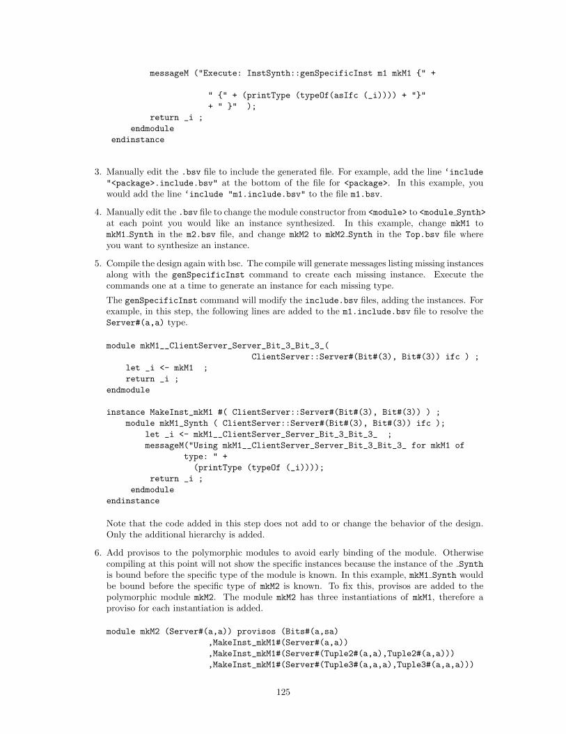
messageM ("Execute: InstSynth::genSpecificInst m1 mkM1 {" +
" {" + (printType (typeOf(asIfc (_i)))) + "}"
+ " }" );
return _i ;
endmodule
endinstance
3. Manually edit the .bsv file to include the generated file. For example, add the line ‘include
"<package>.include.bsv" at the bottom of the file for <package>. In this example, youwould add the line ‘include "m1.include.bsv" to the file m1.bsv.
4. Manually edit the .bsv file to change the module constructor from <module> to <module Synth>
at each point you would like an instance synthesized. In this example, change mkM1 tomkM1 Synth in the m2.bsv file, and change mkM2 to mkM2 Synth in the Top.bsv file whereyou want to synthesize an instance.
5. Compile the design again with bsc. The compile will generate messages listing missing instancesalong with the genSpecificInst command to create each missing instance. Execute thecommands one at a time to generate an instance for each missing type.
The genSpecificInst command will modify the include.bsv files, adding the instances. Forexample, in this step, the following lines are added to the m1.include.bsv file to resolve theServer#(a,a) type.
module mkM1__ClientServer_Server_Bit_3_Bit_3_(
ClientServer::Server#(Bit#(3), Bit#(3)) ifc ) ;
let _i <- mkM1 ;
return _i ;
endmodule
instance MakeInst_mkM1 #( ClientServer::Server#(Bit#(3), Bit#(3)) ) ;
module mkM1_Synth ( ClientServer::Server#(Bit#(3), Bit#(3)) ifc );
let _i <- mkM1__ClientServer_Server_Bit_3_Bit_3_ ;
messageM("Using mkM1__ClientServer_Server_Bit_3_Bit_3_ for mkM1 of
type: " +
(printType (typeOf (_i))));
return _i ;
endmodule
endinstance
Note that the code added in this step does not add to or change the behavior of the design.Only the additional hierarchy is added.
6. Add provisos to the polymorphic modules to avoid early binding of the module. Otherwisecompiling at this point will not show the specific instances because the instance of the Synth
is bound before the specific type of the module is known. In this example, mkM1 Synth wouldbe bound before the specific type of mkM2 is known. To fix this, provisos are added to thepolymorphic module mkM2. The module mkM2 has three instantiations of mkM1, therefore aproviso for each instantiation is added.
module mkM2 (Server#(a,a)) provisos (Bits#(a,sa)
,MakeInst_mkM1#(Server#(a,a))
,MakeInst_mkM1#(Server#(Tuple2#(a,a),Tuple2#(a,a)))
,MakeInst_mkM1#(Server#(Tuple3#(a,a,a),Tuple3#(a,a,a)))
125
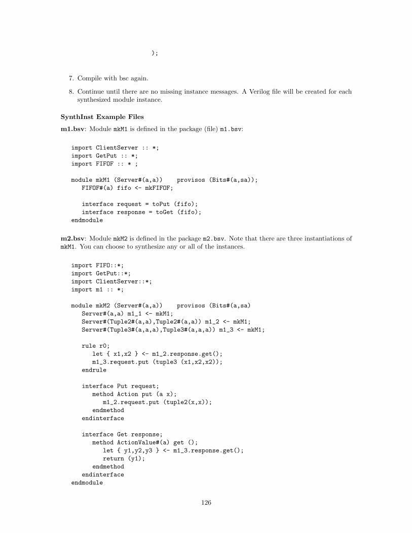
);
7. Compile with bsc again.
8. Continue until there are no missing instance messages. A Verilog file will be created for eachsynthesized module instance.
SynthInst Example Files
m1.bsv: Module mkM1 is defined in the package (file) m1.bsv:
import ClientServer :: *;
import GetPut :: *;
import FIFOF :: * ;
module mkM1 (Server#(a,a)) provisos (Bits#(a,sa));
FIFOF#(a) fifo <- mkFIFOF;
interface request = toPut (fifo);
interface response = toGet (fifo);
endmodule
m2.bsv: Module mkM2 is defined in the package m2.bsv. Note that there are three instantiations ofmkM1. You can choose to synthesize any or all of the instances.
import FIFO::*;
import GetPut::*;
import ClientServer::*;
import m1 :: *;
module mkM2 (Server#(a,a)) provisos (Bits#(a,sa)
Server#(a,a) m1_1 <- mkM1;
Server#(Tuple2#(a,a),Tuple2#(a,a)) m1_2 <- mkM1;
Server#(Tuple3#(a,a,a),Tuple3#(a,a,a)) m1_3 <- mkM1;
rule r0;
let { x1,x2 } <- m1_2.response.get();
m1_3.request.put (tuple3 (x1,x2,x2));
endrule
interface Put request;
method Action put (a x);
m1_2.request.put (tuple2(x,x));
endmethod
endinterface
interface Get response;
method ActionValue#(a) get ();
let { y1,y2,y3 } <- m1_3.response.get();
return (y1);
endmethod
endinterface
endmodule
126
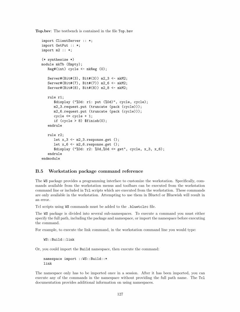
Top.bsv: The testbench is contained in the file Top.bsv
import ClientServer :: *;
import GetPut :: *;
import m2 :: *;
(* synthesize *)
module mkTb (Empty);
Reg#(int) cycle <- mkReg (0);
Server#(Bit#(3), Bit#(3)) m2_3 <- mkM2;
Server#(Bit#(7), Bit#(7)) m2_6 <- mkM2;
Server#(Bit#(8), Bit#(8)) m2_8 <- mkM2;
rule r1;
$display ("%0d: r1: put (%0d)", cycle, cycle);
m2_3.request.put (truncate (pack (cycle)));
m2_6.request.put (truncate (pack (cycle)));
cycle <= cycle + 1;
if (cycle > 8) $finish(0);
endrule
rule r2;
let x_3 <- m2_3.response.get ();
let x_6 <- m2_6.response.get ();
$display ("%0d: r2: %0d,%0d <= get", cycle, x_3, x_6);
endrule
endmodule
B.5 Workstation package command reference
The WS package provides a programming interface to customize the workstation. Specifically, com-mands available from the workstation menus and toolbars can be executed from the workstationcommand line or included in Tcl scripts which are executed from the workstation. These commandsare only available in the workstation. Attempting to use them in Bluetcl or Bluewish will result inan error.
Tcl scripts using WS commands must be added to the .bluetclrc file.
The WS package is divided into several sub-namespaces. To execute a command you must eitherspecify the full path, including the package and namespace, or import the namespace before executingthe command.
For example, to execute the link command, in the workstation command line you would type:
WS::Build::link
Or, you could import the Build namespace, then execute the command:
namespace import ::WS::Build::*
link
The namespace only has to be imported once in a session. After it has been imported, you canexecute any of the commands in the namespace without providing the full path name. The Tcl
documentation provides additional information on using namespaces.
127
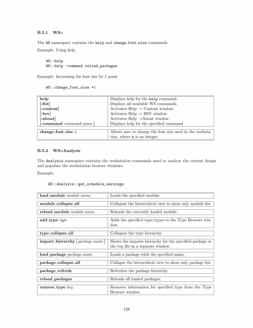
B.5.1 WS::
The WS namespace contains the help and change font size commands.
Example: Using help
WS::help
WS::help -command reload_packages
Example: Increasing the font size by 1 point
WS::change_font_size +1
help Displays help for the help command.[-list] Displays all available WS commands.[-content] Activates Help → Content window.[-bsv] Activates Help → BSV window.[-about] Activates Help →About window.[-command command name ] Displays help for the specified command
change font size n Allows user to change the font size used in the worksta-tion, where n is an integer.
B.5.2 WS::Analysis
The Analysis namespace contains the workstation commands used to analyze the current designand populate the workstation browser windows.
Example:
WS::Analysis::get_schedule_warnings
load module module name Loads the specified module.
module collapse all Collapses the hierarchical view to show only module list.
reload module module name Reloads the currently loaded module.
add type type Adds the specified type/types to the Type Browser win-dow.
type collapse all Collapses the type hierarchy.
import hierarchy [ package name ] Shows the imports hierarchy for the specified package orthe top file in a separate window.
load package package name Loads a package with the specified name.
package collapse all Collapse the hierarchical view to show only package list.
package refresh Refreshes the package hierarchy.
reload packages Reloads all loaded packages.
remove type key Removes information for specified type from the TypeBrowser window.
128
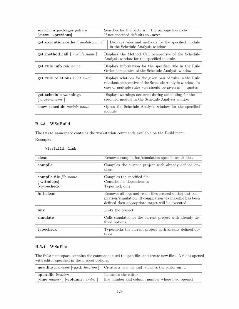
search in packages pattern Searches for the pattern in the package hierarchy.[-next | -previous] If not specified defaults to -next.
get execution order [ module name ] Displays rules and methods for the specified modulein the Schedule Analysis window.
get method call [ module name ] Displays the Method Call perspective of the ScheduleAnalysis window for the specified module.
get rule info rule name Displays information for the specified rule in the RuleOrder perspective of the Schedule Analysis window.
get rule relations rule1 rule2 Displays relations for the given pair of rules in the Rulerelations perspective of the Schedule Analysis window. Incase of multiple rules rule should be given in ”” quotes
get schedule warnings Displays warnings occurred during scheduling for the[ module name ] specified module in the Schedule Analysis window.
show schedule module name Opens the Schedule Analysis window for the specifiedmodule.
B.5.3 WS::Build
The Build namespace contains the workstation commands available on the Build menu.
Example:
WS::Build::link
clean Removes compilation/simulation specific result files.
compile Compiles the current project with already defined op-tions.
compile file file name Compiles the specified file.[-withdeps] Consider file dependencies[-typecheck] Typecheck only
full clean Removes all logs and result files created during last com-pilation/simulation. If compilation via makefile has beendefined then appropriate target will be executed.
link Links the project
simulate Calls simulator for the current project with already de-fined options.
typecheck Typechecks the current project with already defined op-tions.
B.5.4 WS::File
The File namespace contains the commands used to open files and create new files. A file is openedwith editor specified in the project options.
new file file name [-path location ] Creates a new file and launches the editor on it.
open file location Launches the editor[-line number ] [-column number ] line number and column number where filed opened
129
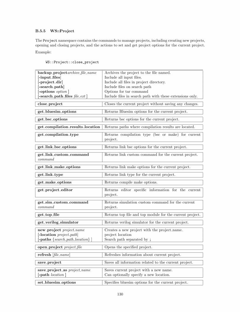
B.5.5 WS::Project
The Project namespace contains the commands to manage projects, including creating new projects,opening and closing projects, and the actions to set and get project options for the current project.
Example:
WS::Project::close_project
backup projectarchive file name Archives the project to the file named.[-input files] Include all input files.[-project dir] Include all files in project directory.[-search path] Include files on search path[-options option ] Options for tar command[-search path files file ext ] Include files in search path with these extensions only.
close project Closes the current project without saving any changes.
get bluesim options Returns Bluesim options for the current project.
get bsc options Returns bsc options for the current project.
get compilation results location Returns paths where compilation results are located.
get compilation type Returns compilation type (bsc or make) for currentproject.
get link bsc options Returns link bsc options for the current project.
get link custom command Returns link custom command for the current project.command
get link make options Returns link make options for the current project.
get link type Returns link type for the current project.
get make options Returns compile make options.
get project editor Returns editor specific information for the currentproject.
get sim custom command Returns simulation custom command for the currentcommand project.
get top file Returns top file and top module for the current project.
get verilog simulator Returns verilog simulator for the current project.
new project project name Creates a new project with the project name.[-location project path] project location[-paths {search path location} ] Search path separated by ;
open project project file Opens the specified project.
refresh [file name] Refreshes information about current project.
save project Saves all information related to the current project.
save project as project name Saves current project with a new name.[-path location ] Can optionally specify a new location.
set bluesim options Specifies bluesim options for the current project.
130
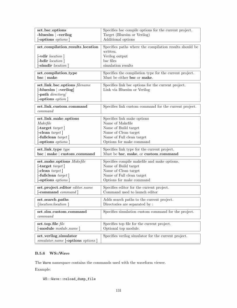
set bsc options Specifies bsc compile options for the current project.-bluesim | -verilog Target (Bluesim or Verilog)[-options options ] Additional options
set compilation results location Specifies paths where the compilation results should bewritten.
[-vdir location ] Verilog output[-bdir location ] bsc files[-simdir location ] simulation results
set compilation type Specifies the compilation type for the current project.bsc | make Must be either bsc or make.
set link bsc options filename Specifies link bsc options for the current project.[-bluesim | -verilog] Link via Bluesim or Verilog[-path directory][-options option ]
set link custom command Specifies link custom command for the current project.command
set link make options Specifies link make optionsMakefile Name of Makefile[-target target ] Name of Build target[-clean target ] Name of Clean target[-fullclean target ] Name of Full clean target[-options options ] Options for make command
set link type type Specifies link type for the current project.bsc | make | custom command Must be bsc, make, or custom command
set make options Makefile Specifies compile makefile and make options.[-target target ] Name of Build target[-clean target ] Name of Clean target[-fullclean target ] Name of Full clean target[-options options ] Options for make command
set project editor editor name Specifies editor for the current project.[-command command ] Command used to launch editor
set search paths Adds search paths to the current project.{location:location } Directories are separated by :
set sim custom command Specifies simulation custom command for the project.command
set top file file Specifies top file for the current project.[-module module name ] Optional top module.
set verilog simulator Specifies verilog simulator for the current project.simulator name [-options options ]
B.5.6 WS::Wave
The Wave namespace contains the commands used with the waveform viewer.
Example:
WS::Wave::reload_dump_file
131
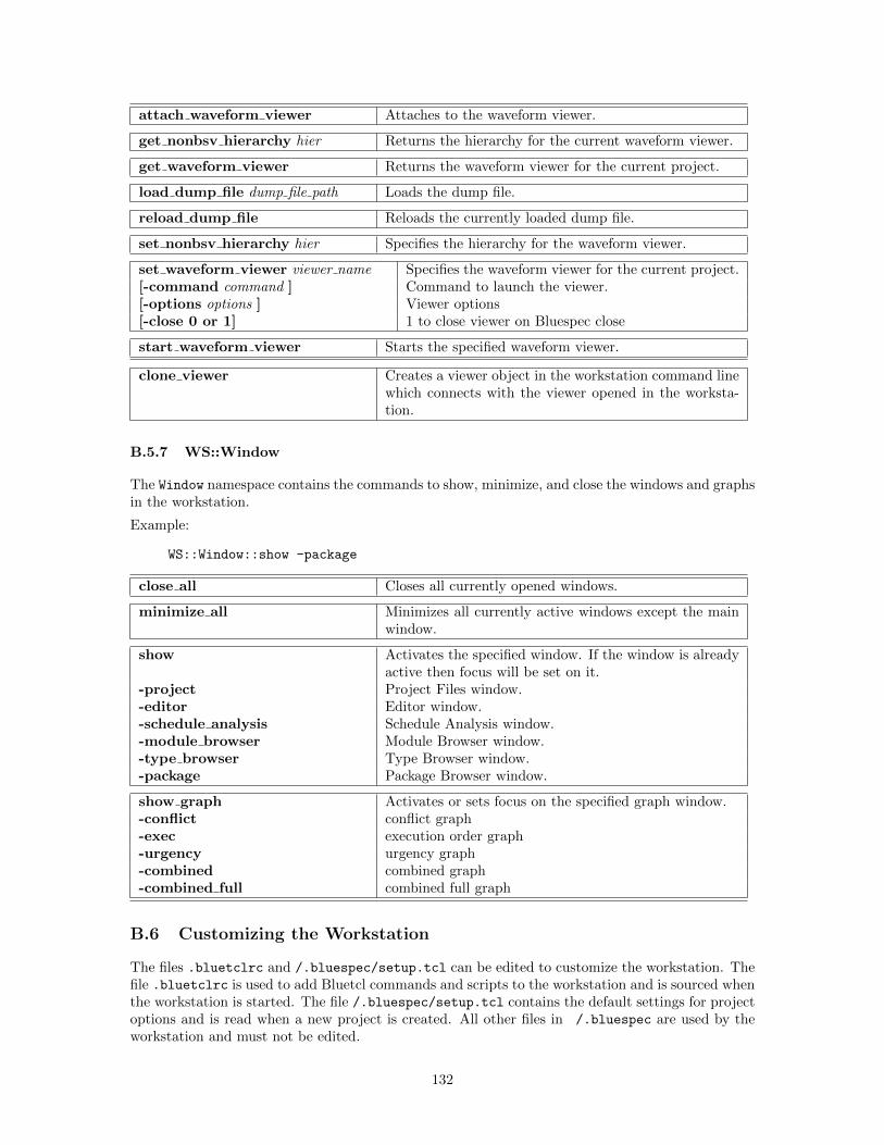
attach waveform viewer Attaches to the waveform viewer.
get nonbsv hierarchy hier Returns the hierarchy for the current waveform viewer.
get waveform viewer Returns the waveform viewer for the current project.
load dump file dump file path Loads the dump file.
reload dump file Reloads the currently loaded dump file.
set nonbsv hierarchy hier Specifies the hierarchy for the waveform viewer.
set waveform viewer viewer name Specifies the waveform viewer for the current project.[-command command ] Command to launch the viewer.[-options options ] Viewer options[-close 0 or 1] 1 to close viewer on Bluespec close
start waveform viewer Starts the specified waveform viewer.
clone viewer Creates a viewer object in the workstation command linewhich connects with the viewer opened in the worksta-tion.
B.5.7 WS::Window
The Window namespace contains the commands to show, minimize, and close the windows and graphsin the workstation.
Example:
WS::Window::show -package
close all Closes all currently opened windows.
minimize all Minimizes all currently active windows except the mainwindow.
show Activates the specified window. If the window is alreadyactive then focus will be set on it.
-project Project Files window.-editor Editor window.-schedule analysis Schedule Analysis window.-module browser Module Browser window.-type browser Type Browser window.-package Package Browser window.
show graph Activates or sets focus on the specified graph window.-conflict conflict graph-exec execution order graph-urgency urgency graph-combined combined graph-combined full combined full graph
B.6 Customizing the Workstation
The files .bluetclrc and /.bluespec/setup.tcl can be edited to customize the workstation. Thefile .bluetclrc is used to add Bluetcl commands and scripts to the workstation and is sourced whenthe workstation is started. The file /.bluespec/setup.tcl contains the default settings for projectoptions and is read when a new project is created. All other files in /.bluespec are used by theworkstation and must not be edited.
132
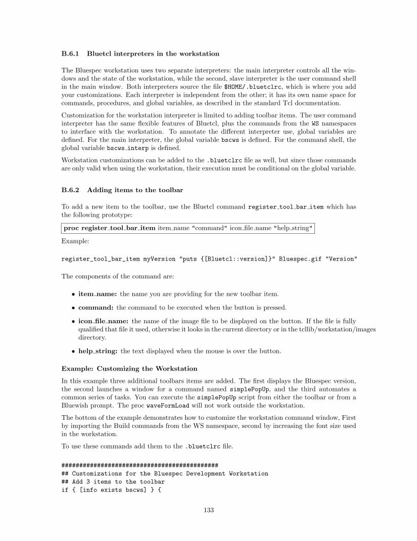
B.6.1 Bluetcl interpreters in the workstation
The Bluespec workstation uses two separate interpreters: the main interpreter controls all the win-dows and the state of the workstation, while the second, slave interpreter is the user command shellin the main window. Both interpreters source the file $HOME/.bluetclrc, which is where you addyour customizations. Each interpreter is independent from the other; it has its own name space forcommands, procedures, and global variables, as described in the standard Tcl documentation.
Customization for the workstation interpreter is limited to adding toolbar items. The user commandinterpreter has the same flexible features of Bluetcl, plus the commands from the WS namespacesto interface with the workstation. To annotate the different interpreter use, global variables aredefined. For the main interpreter, the global variable bscws is defined. For the command shell, theglobal variable bscws interp is defined.
Workstation customizations can be added to the .bluetclrc file as well, but since those commandsare only valid when using the workstation, their execution must be conditional on the global variable.
B.6.2 Adding items to the toolbar
To add a new item to the toolbar, use the Bluetcl command register tool bar item which hasthe following prototype:
proc register tool bar item item name "command" icon file name "help string"
Example:
register_tool_bar_item myVersion "puts {[Bluetcl::version]}" Bluespec.gif "Version"
The components of the command are:
• item name: the name you are providing for the new toolbar item.
• command: the command to be executed when the button is pressed.
• icon file name: the name of the image file to be displayed on the button. If the file is fullyqualified that file it used, otherwise it looks in the current directory or in the tcllib/workstation/imagesdirectory.
• help string: the text displayed when the mouse is over the button.
Example: Customizing the Workstation
In this example three additional toolbars items are added. The first displays the Bluespec version,the second launches a window for a command named simplePopUp, and the third automates acommon series of tasks. You can execute the simplePopUp script from either the toolbar or from aBluewish prompt. The proc waveFormLoad will not work outside the workstation.
The bottom of the example demonstrates how to customize the workstation command window, Firstby importing the Build commands from the WS namespace, second by increasing the font size usedin the workstation.
To use these commands add them to the .bluetclrc file.
############################################
## Customizations for the Bluespec Development Workstation
## Add 3 items to the toolbar
if { [info exists bscws] } {
133
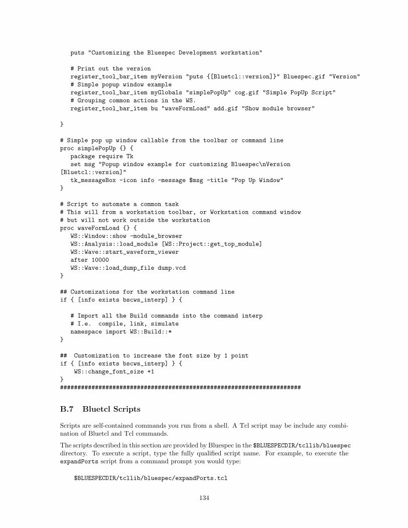
puts "Customizing the Bluespec Development workstation"
# Print out the version
register_tool_bar_item myVersion "puts {[Bluetcl::version]}" Bluespec.gif "Version"
# Simple popup window example
register_tool_bar_item myGlobals "simplePopUp" cog.gif "Simple PopUp Script"
# Grouping common actions in the WS.
register_tool_bar_item bu "waveFormLoad" add.gif "Show module browser"
}
# Simple pop up window callable from the toolbar or command line
proc simplePopUp {} {
package require Tk
set msg "Popup window example for customizing Bluespec\nVersion
[Bluetcl::version]"
tk_messageBox -icon info -message $msg -title "Pop Up Window"
}
# Script to automate a common task
# This will from a workstation toolbar, or Workstation command window
# but will not work outside the workstation
proc waveFormLoad {} {
WS::Window::show -module_browser
WS::Analysis::load_module [WS::Project::get_top_module]
WS::Wave::start_waveform_viewer
after 10000
WS::Wave::load_dump_file dump.vcd
}
## Customizations for the workstation command line
if { [info exists bscws_interp] } {
# Import all the Build commands into the command interp
# I.e. compile, link, simulate
namespace import WS::Build::*
}
## Customization to increase the font size by 1 point
if { [info exists bscws_interp] } {
WS::change_font_size +1
}
#####################################################################
B.7 Bluetcl Scripts
Scripts are self-contained commands you run from a shell. A Tcl script may be include any combi-nation of Bluetcl and Tcl commands.
The scripts described in this section are provided by Bluespec in the $BLUESPECDIR/tcllib/bluespecdirectory. To execute a script, type the fully qualified script name. For example, to execute theexpandPorts script from a command prompt you would type:
$BLUESPECDIR/tcllib/bluespec/expandPorts.tcl
134
If you are already in a Tcl shell, type exec before the script name:
exec $BLUESPECDIR/tcllib/bluespec/expandPorts.tcl
To execute your own Tcl scripts from within the Bluespec development workstation they need to beadded to the workstation in the ~/.bluetclrc file.
B.7.1 expandPorts
Script to create a Verilog wrapper file which expands structures into separate Verilog ports.
Usage:
expandPorts.tcl {options} packname modname module.v
options Optional command line switches:-p path path, if supplied to the bsc command-verilog compile to verilog (default)-sim compile to bluesim-include outfile output file for include.vh-wrapper outfile output file for wrapper.v-rename file.tcl Tcl script creating rename pin structure-makerename Create empty .rename.tcl file to edit for -rename-interface name Interface to expand - defaults to package name (packname)packname Name of the input .bo file.modname Name of the top level module.module.v bsc generated Verilog (.v) file for the module being wrapped.
135
Index
+ (Bluesim simulation flag), 94+bsccycle (Verilog simulation), 23, 37+bscvcd (Verilog simulation), 23, 37-D (compiler flag), 67-E (compiler flag), 67-Hsize (compiler flag), 67-I (compiler flag), 35, 65-Ksize (compiler flag), 67-L (compiler flag), 35, 39-V, 23-V (Bluesim simulation flag), 94-Xc++ (compiler flag), 74-Xcpp (compiler flag), 74-Xc (compiler flag), 74-Xl (compiler flag), 74-Xv (compiler flag), 63-aggressive-conditions (compiler flag), 68-bdir (compiler flag), 65-c (Bluesim simulation flag), 94-check-assert (compiler flag), 70-continue-after-errors (compiler flag), 70-cpp (compiler flag), 74demote-errors (compiler flag), 70-e (compiler flag), 61-elab (compiler flag), 61-f (Bluesim simulation flag), 94-fdir (compiler flag), 65-g (compiler flag), 28, 29, 31, 61-h (Bluesim simulation flag), 94-help (compiler flag), 61-i (compiler flag), 65-info-dir (compiler flag), 65-keep-fires (compiler flag), 70-keep-inlined-boundaries (compiler flag),
70-l (compiler flag), 35, 39, 65-license-type (compiler flag), 66-licenseWarning (compiler flag), 66-lift (compiler flag), 68-m (Bluesim simulation flag), 94-no (compiler flag), 61-no-runtime-license (compiler flag), 66-o (compiler flag), 61-opt-undetermined-vals (compiler flag), 69-p (compiler flag), 65-parallel-sim-link (compiler flag), 64-print-expiration (compiler flag), 66-print-flags (compiler flag), 67promote-warnings (compiler flag), 70-remove-dollar (compiler flag), 63
-remove-empty-rules (compiler flag), 70-remove-false-rules (compiler flag), 70-remove-starved-rules (compiler flag), 70-remove-unused-modules (compiler flag), 63-reset-prefix (compiler flag), 67-resource-off (compiler flag), 65-resource-simple (compiler flag), 65-runtime-license (compiler flag), 66-sat-cudd (compiler flag), 70-sat-stp (compiler flag), 70-sat-yices (compiler flag), 70-scemi (compiler flag), 64-scemi-classic (compiler flag), 64-scemiTB (compiler flag), 64-sched-dot (compiler flag), 28, 49, 72-scheduler-effort (compiler flag), 70-show-compiles (compiler flag), 68, 80-show-elab-progress (compiler flag), 70, 76-show-license-detail (compiler flag), 66-show-method-bvi (compiler flag), 87-show-method-conf (compiler flag), 70, 87-show-module-use (compiler flag), 70-show-range-conflict (compiler flag), 70-show-rule-rel (compiler flag), 72, 81-show-schedule (compiler flag), 72, 81-show-stats (compiler flag), 70-sim (compiler flag), 29, 61-simdir (compiler flag), 65-split-if (compiler flag), 68-steps (compiler flag), 67-steps-max-intervals (compiler flag), 67-steps-warn-interval (compiler flag), 67-suppress-warnings (compiler flag), 70-systemc (compiler flag), 35, 64-u (compiler flag), 61, 68, 80-unspecified-to (compiler flag), 63-v (Bluesim simulation flag), 94-v (compiler flag), 61, 81-v95 (compiler flag), 63-vdir (compiler flag), 65-verbose (compiler flag), 61-verilog (compiler flag), 29, 61-verilog-filter (compiler flag), 63-vsearch (compiler flag), 37, 65-vsim (compiler flag), 37, 61-w (Bluesim simulation flag), 94-wait-for-license (compiler flag), 66-warn-action-shadowing (compiler flag), 70-warn-method-urgency (compiler flag), 70-warn-scheduler-effort (compiler flag), 70
136
.ba, 28
.ba (file type), 12
.bluetclrc, 105, 127, 133
.bo, 27, 28
.bo (file type), 12, 31
.bspec, 17
.bsv (file type), 12
.cxx (file type), 12
.h (file type), 12
.info file, 54
.o (file type), 12
.v, 28
.v (file type), 12
.xcf (synthesis script), 38, 83%B (meta variable), 18, 19%F (meta variable), 18%M (meta variable), 18, 19%P (meta variable), 18, 19%SCM (meta variable), 18%SCP (meta variable), 18
attributesdescending urgency, 51preempts, 49synthesize, 28, 29
automatic recompilation, 68, 80
backup, 53Bluesim, 32, 92
importing C functions, 34interactive mode, 95linking .ba files, 33MCD, 101multiple clock domains, 101scripting, 95, 100
commands, 95navigation, 98
simulation flags, 94Bluesim back end, 33, 34, 64, 65, 92Bluesim flags, 64, 94BLUESPEC HOME, 8, 102BLUESPEC LICENSE FILE, 9, 102BLUESPECDIR, 8, 102BLUESPECTMP, 103Bluetcl, 10BLUETCL OPTIONS, 102bpackage (bluetcl command), 106BROWSER, 103bsc, 22bsc flags, 60BSC CFLAGS, 103BSC CXXFLAGS, 103BSC MAKEFLAGS, 103BSC OPTIONS, 62, 102
BSC TRACE SCEMI EVE, 103BSC TRACE SCEMI PCIE, 103BSC TRACE SCEMI TCP, 103BSC VERILOG SIM, 102build, 27
CC, 103clean, 40code generation, 29combined (scheduling graph), 52combined full (scheduling graph), 52compilation, 31compile, 13, 28compile flags, 61compile options, 20compile with deps, 29compiler flags, using, 21Compiler messages, 74compiler messages, 16, 46compiler optimizations, 69compiler transformations, 68conflict (scheduling graph), 50cver (Verilog simulator), 37CXX, 103
debugging flags, 70default project settings, 17default settings, 17, 18defs (bluetcl command), 106descending urgency attribute, 51documentation, 10
EDITOR, 103editor options, 24elaboration error messages, 75emacs, 24emacs (text editor), 11enscript, 11environment variables, 102
BLUESPECDIR, 8, 102BLUESPECTMP, 103BLUESPEC HOME, 8, 102BLUESPEC LICENSE FILE, 9, 102BLUETCL OPTIONS, 102BROWSER, 103BSC CFLAGS, 103BSC CXXFLAGS, 103BSC MAKEFLAGS, 103BSC OPTIONS, 102BSC TRACE SCEMI EVE, 103BSC TRACE SCEMI PCIE, 103BSC TRACE SCEMI TCP, 103BSC VERILOG SIM, 102CC, 103CXX, 103
137
EDITOR, 103GHCRTS, 102HOME, 102LM LICENSE FILE, 9, 102SYSTEMC, 102TMP, 103
error messages, 74execution order (scheduling graph), 50
file types, 12filter, 50flags (bluetcl command), 106FLEXnet, 9font size, 16, 128, 133FSDB, 39
Bluesim, 101Verilog, 37Viewing, 44
full clean, 40
GHCRTS, 102graphviz, 14, 49GtkWave, 25gvim, 24
help (bluetcl command), 106HOME, 102
import, 41import BDPI, 32import BVI, 32, 33, 53import BVI wizard, 53import packages, 28importBDPI, 34, 38importing C, 32, 34, 38importing foreign functions, 31importing packages, 30importing Verilog, 32, 33, 38installing, 7isim (Verilog simulator), 37iverilog (Verilog simulator), 37
jedit (text editor), 11
library packages, 30licensing, 9link, 13, 32link options, 22linking, 32linking flags, 61LM LICENSE FILE, 9, 102
Makefile, 103makefile
exporting, 53
using, 21, 23, 40meta variable, 21, 23meta variables, 18, 23
%B, 18%F, 18%M, 18%P, 18%SCM, 18%SCP, 18
modelsim (Verilog simulator), 37module (bluetcl command), 107
ncverilog (Verilog simulator), 37
options, 18files, 25
package, 41path flags, 65path messages, 78positive reset, 84preempts attribute, 49progress messages, 79project, 17
reset, 84resource scheduling, 65rule (bluetcl command), 107rules, 87run-time flags, 67
save, 26save placement, 26Sce-Mi, 24SceMi, 64schedule (bluetcl command), 107scheduling, 81scheduling graphs, 49
combined, 52combined full, 52conflict, 50execution order, 50urgency, 51
scheduling messages, 77script file, 121search path, 19selecting modules, 29settings
compile options, 20default, 17, 18editor options, 24link options, 22Project Options menu, 18Sce-Mi options, 24search path, 19
138
simulate options, 23waveform viewer options, 25
sim (bluesim command), 108sim (bluetcl command), 107simulate options, 23SpringSoft/Novas, 25state elements, 85submodule (bluetcl command), 108synthesize (attribute), 29, 31synthesize attribute, 28, 29SYSTEMC, 102SystemC
linking .ba files, 35SystemC back end, 35
Tcl, 15Tcldot, 9, 14, 49TMP, 103top file, 29top module, 28top package, 41type (bluetcl command), 108type check, 27type-checking error messages, 75
urgency (scheduling graph), 51utilities, 11
value change dumpBluesim, 101Verilog, 37
VCD, 39Bluesim, 101Verilog, 37Viewing, 44
vcs (Verilog simulator), 37vcsi (Verilog simulator), 37Verilog, 28, 32
importing, 32linking, 37simulator, 37
Verilog back end, 37, 38, 63, 65, 83Verilog flags, 63Verilog header comment, 87Verilog ports, 83Verilog Procedural Interface (VPI), 32, 38Verilog simulator
cver, 37isim, 37iverilog, 37modelsim, 37ncverilog, 37vcs, 37vcsi, 37veriwell, 37
veriwell (Verilog simulator), 37version (bluetcl command), 108VHDL, 38view source, 42vim (text editor), 11
warnings messages, 74waveform viewer
GtkWave, 25options, 25, 45SpringSoft/Novas, 25using, 43
window placement, 26wizard (import BVI), 53
Xilinx synthesis script, 38, 83
139
Commands by Namespace
Bluesimsim, 108
Bluetclbpackage, 106defs, 106flags, 106help, 106module, 107rule, 107schedule, 107sim, 107submodule, 108type, 108version, 108
Typesimport package, 110show types, 110
Virtualinst, 111omap, 115reset, 115signal, 113
Wavescreate viewer, 119get nonbsv hierarchy, 119set nonbsv hierarchy, 119
WSchange font size, 128help, 128
WS::Analysisadd type, 128get execution order, 129get method call, 129get rule info, 129get rule relations, 129get schedule warnings, 129import hierarchy, 128load module, 128load package, 128module collapse all, 128package collapse all, 128package refresh, 128reload module, 128reload packages, 128remove type, 128search in packages, 128show schedule, 129
type collapse all, 128WS::Build
clean, 129compile, 129compile file, 129full clean, 129link, 129simulate, 129typecheck, 129
WS::Filenew file, 129open file, 129
WS::Projectbackup project, 130close project, 130get bluesim options, 130get bsc options, 130get compilation results location, 130get compilation type, 130get link bsc options, 130get link custom command, 130get link make options, 130get link type, 130get make options, 130get project editor, 130get sim custom command, 130get top file, 130get verilog simulator, 130new project, 130open project, 130refresh, 130save project, 130save project as, 130set bluesim options, 130set bsc options, 130set compilation results location, 131set compilation type, 131set link bsc options, 131set link custom command, 131set link make options, 131set link type, 131set make options, 131set project editor, 131set search paths, 131set sim custom command, 131set top file, 131set verilog simulator, 131
WS::Waveattach waveform viewer, 132clone viewer, 132
140
get nonbsv hierarchy, 132get waveform viewer, 132load dump file, 132reload dump file, 132set nonbsv hierarchy, 132set waveform viewer, 132start waveform viewer, 132
WS::Windowclose all, 132minimize all, 132show, 132show graph, 132
141

1
142