blowing lance technlogies
TRANSCRIPT
ADVANCED EAF OXYGEN USAGE AT VALLOUREC-MANNESMANN SAINT SAULVE STEELWORKS
S. Cantacuzene, M. Grant, P. Boussard, M. Devaux
Air Liquide ACI LLC R. Carreno, O. Laurence, C. Dworatzek Vallourec-Mannesmann Saint Saulve
Abstract: Oxygen usage has played a crucial role in the ongoing EAF process improvement and has enabled furnace operators to optimize the chemical energy input, reaching unprecedented efficiencies and productivity. This article will present the fundamental principles governing the design of an optimized chemical energy system through scrap oxy-cutting and melting, decarburisation, post-combustion and slag foaming. It will be illustrated with industrial results obtained at the Vallourec Mannesmann Saint-Saulve site, where a PyreJet™ and ALARC™ PC system, using the newly designed DRAGON Panel, has been recently commissioned.
The need for an optimized chemical energy system Electric Arc Furnaces have been continuously improving over the past 30 years and have now reached unprecedented levels of efficiency and sophistication. In a market where offer and demand are closely coupled and where quality criteria are becoming more stringent, the improvement of the EAF’s operating process is an ongoing necessity. A significant effort is being made by every steelmaker worldwide to continuously increase its furnace’s output while, at the same time, reducing the conversion costs. One way to achieve this goal is by globally optimizing the furnace’s energy usage and especially by lowering the specific electrical energy consumption. These goals can be achieved by:
- Improving the energy usage outside the furnace by extensive usage of ladle furnace, by pre-heating the scrap, by pre-heating the ladle and by reducing delays and arc-off time through preventive maintenance, training and improved logistics.
- Improving the energy usage inside the furnace by improving the efficiency (slag foaming) of utilizing the oxidizing exothermic chemical reactions in the bath (through O2 and Carbon injection), radiant heating and melting of scrap by oxy-fuel burners and by post-combustion of the CO inside the EAF volume.
The lowest cost and least invasive method for improving performance of an EAF is to increase the efficiency and usage of oxygen through oxy-burners and multiple point supersonic lancing.
This paper will focus on the specifics of the oxygen usage in the EAF and on existing technologies designed to make it most efficient.
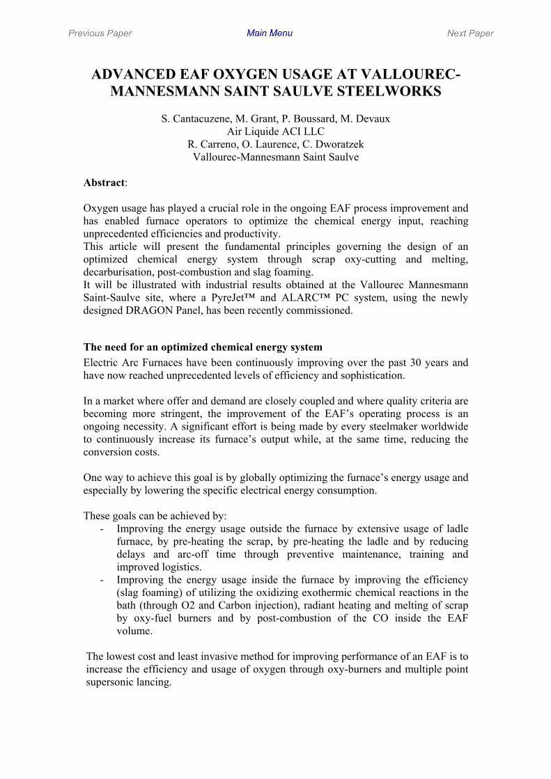
Usage of oxy-fuel burners With the advance of the ultra high power (UHP) EAFs, the use of oxy-fuel burners in the furnace has became a necessity in order to increase the rate scrap melting in cold spots, and, thereby, make scrap melting more uniform. In order to be successful in the stringent EAF environment an oxy-fuel burner has not only to provide efficient heat transfer but also needs to possess the following characteristics: • Robustness and resistance to plugging, • Resistance for flame rebound from the scrap, • Long life time and low maintenance requirements. There are several approaches to the EAF burner design, the most common being a ‘pipe inside a pipe’ arrangement, having oxygen supply through the center pipe and natural gas supply through annular opening between the center pipe and a concentric pipe of a larger diameter. Although very simple in fabrication, this design has an inherited flaw:there is typically a lack of cooling of the pipes that leads to quick burner destruction by flame rebounding from scrap back inside the burner. A more innovative design (Fig. 1) incorporates a number of fuel and peripheral oxygen openings via a copper tip (1). The copper tip being very conductive, excess heat is quickly transferred to an outside cooling source.
Figure 1: Air Liquide ACI PyrOx Burner Concept
In addition to a plurality of peripheral openings for gas and oxygen injection, it has a water-cooled combustion chamber that protects the openings from steel and slag splashing as well as improves the mixing of gases at the nozzle exit. The oxy-fuel burner is generally used at full power only during the scrap heating and melting step and is maintained in a low-flow holding mode during decarburization of the liquid steel.
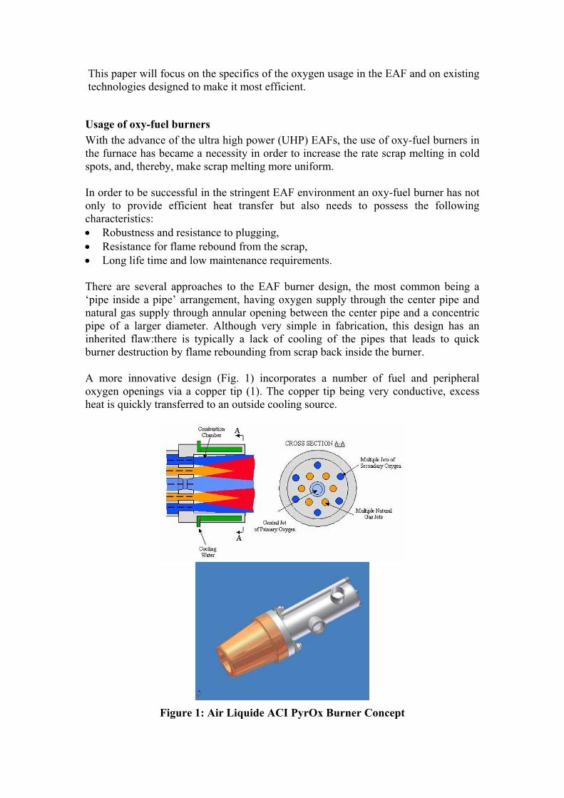
Usage of supersonic injection tuyeres During the decarburization / refining stage oxygen is injected into the steel to reduce the level of carbon in the metal bath to levels often below 0.1% and therefore help transfer phosphorus and other elements to the slag. An optimal usage of oxygen must allow for a deep penetration of the gas molecules inside the molten bath (for an increased oxygen yield) and for a balanced repartition of the oxygen inside the steel (several injection points, to maintain a low FeO level inside the slag and therefore a high steel yield). Mechanical and operator manipulated lances, which were the dominant technologies for the last 30 years, have been replaced in the last 5 years by highly optimized supersonic Laval nozzle tuyeres. This change from moving door lances to fixed wall mounted injectors, while reducing maintenance and improving safety, has also increased the air- tightness of the EAF furnace (by allowing the slag door to be closed) and therefore has reduced the energy loss through off-gas heat. Air Liquide has conducted intensive supersonic jet studies both through modeling and high temperature experiments (4). The result of these studies is an optimized supersonic nozzle, ALARC-Jet, which minimizes internal jet turbulence as schematically shown in Fig. 2
Standard Supersonic Nozzle Internal turbulence will disturb the jet and cause it to expand
ALARC-JET Supersonic Nozzle Optimized design protects the jet from turbulence
Computer Modelling of Standard Nozzle: The Jet is expanding and losing speed
Computer Modelling of ALARC-Jet Nozzle The Jet stays focused and at high velocity
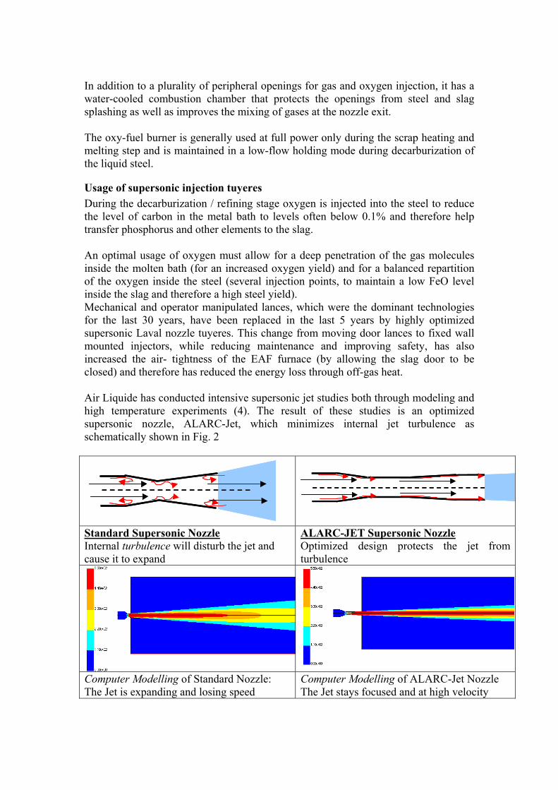
ALARC-JET (red line): the jet maintains exit velocity for a distance of up to 40 nozzle diameters. Standard Laval nozzle (black line): the jet velocity is significantly reduced after only 20 nozzle diameters.
t shape in cold atmosphere for non-adapted conditions ( 3 bart shape in cold atmosphere for non-adapted conditions ( 3 bar ALARC JET : Jet shape in hot atmosphere (1050°C)ALARC JET : Jet shape in hot atmosphere (1050°C)
Experimental Laser Visualization of standard Laval nozzle: the jet is quickly expanding
Experimental visualization of ALARC-JET in hot atmosphere: the supersonic jet stays focus.
Figure 2: Optimized nozzle design, modeling and experimental results Flat bath EAF processes such as CONSTEEL as well as operations with high percentage of DRI, HBI or hot metal in the scrap mix do not require burners for scrap preheating and melting. In such high temperature furnace environments an optimized nozzle such as ALARC Jet has proved to be very effective, allowing for decarburization speeds between 0.1% and 0.15% of C reduction per minute (ref: paper to be published at AISTech 2005)
Usage of Multi-function injection burners When furnace operation is batch-type scrap based, the need for burners in the heating stage and the need to protect the oxygen jet from the colder furnace atmosphere during the refining stage make the multi-function supersonic injection burners today’s most flexible tool. Although common in approach, the different injector technologies vary significantly in design and implementation, which affects both performance and reliability.

A multi-function tool, such as Air Liquide ACI’s Pyrejet Burner, combines the advantage of an inner optimized ALARC-Jet type of nozzle with the outer efficient design of a PyrOx oxy-fuel burner. Carbon is injected through the same device and proper injection angles and speeds allow for its transfer to the liquid metal using the Venturi effect. Fig 4. The multi tool can be used following pre-programmed modes: • Hold mode (to prevent plugging), • Burner mode (to heat and melt scrap), • Soft lancing mode (to enhance slag foaming when the liquid steel level is low) • Supersonic lancing mode (for slag foaming and decarburization) in which the burner’s
flame shrouds and protects • the central oxygen jet.
Figure 4: Injector PyreJetTM assembly
Carbon Injection Pipe
Burner with supersonic nozzle
Combustion Chamber
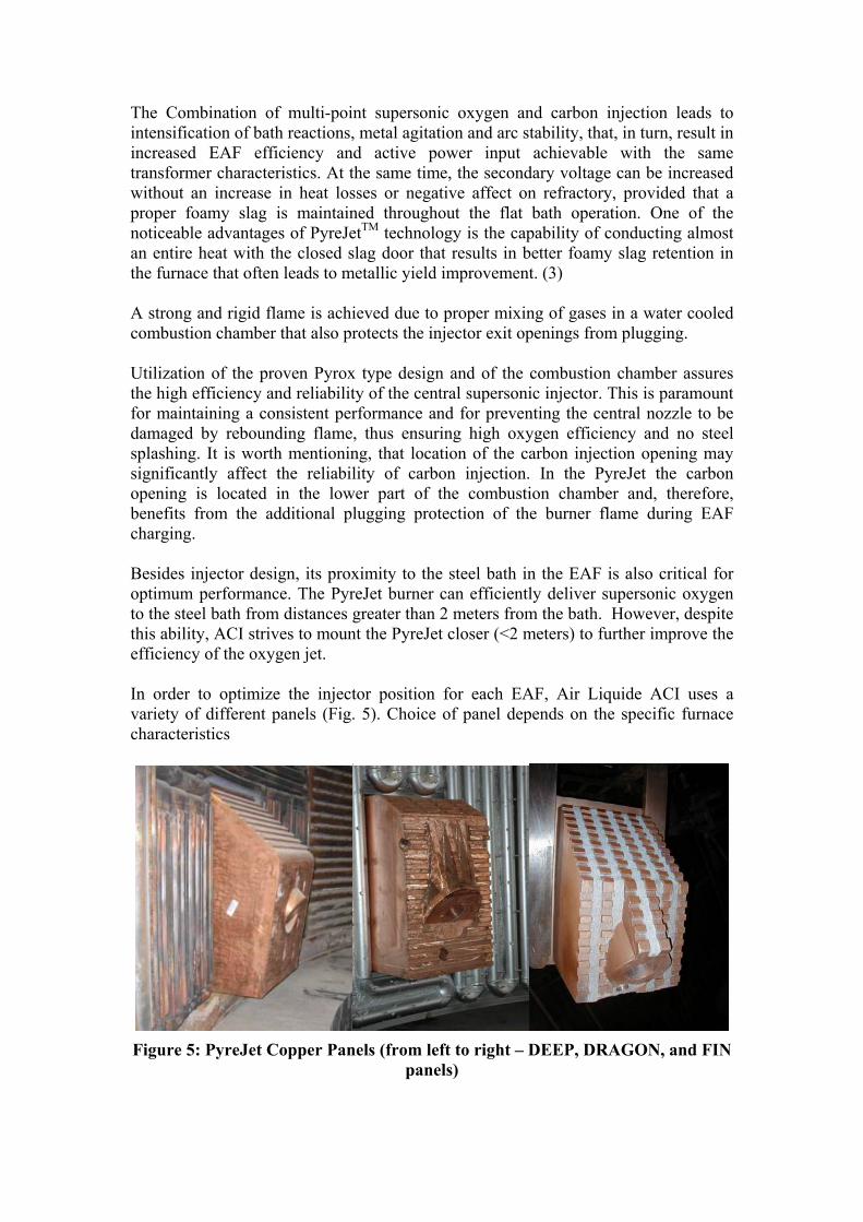
The Combination of multi-point supersonic oxygen and carbon injection leads to intensification of bath reactions, metal agitation and arc stability, that, in turn, result in increased EAF efficiency and active power input achievable with the same transformer characteristics. At the same time, the secondary voltage can be increased without an increase in heat losses or negative affect on refractory, provided that a proper foamy slag is maintained throughout the flat bath operation. One of the noticeable advantages of PyreJetTM technology is the capability of conducting almost an entire heat with the closed slag door that results in better foamy slag retention in the furnace that often leads to metallic yield improvement. (3) A strong and rigid flame is achieved due to proper mixing of gases in a water cooled combustion chamber that also protects the injector exit openings from plugging. Utilization of the proven Pyrox type design and of the combustion chamber assures the high efficiency and reliability of the central supersonic injector. This is paramount for maintaining a consistent performance and for preventing the central nozzle to be damaged by rebounding flame, thus ensuring high oxygen efficiency and no steel splashing. It is worth mentioning, that location of the carbon injection opening may significantly affect the reliability of carbon injection. In the PyreJet the carbon opening is located in the lower part of the combustion chamber and, therefore, benefits from the additional plugging protection of the burner flame during EAF charging. Besides injector design, its proximity to the steel bath in the EAF is also critical for optimum performance. The PyreJet burner can efficiently deliver supersonic oxygen to the steel bath from distances greater than 2 meters from the bath. However, despite this ability, ACI strives to mount the PyreJet closer (<2 meters) to further improve the efficiency of the oxygen jet. In order to optimize the injector position for each EAF, Air Liquide ACI uses a variety of different panels (Fig. 5). Choice of panel depends on the specific furnace characteristics
Figure 5: PyreJet Copper Panels (from left to right – DEEP, DRAGON, and FIN
panels)
The main criteria for selecting the right panel type are brick length and distance from metal level to the injector. Flat panels are primarily used for smaller EAFs where distances to the steel bath are much smaller than large furnaces. Larger furnaces typically require installation of deeper panels (DEEP, DRAGON or FIN) in order to reduce refractory erosion by extending the jet / bath impact point away from the brickwork. The FIN panel is ACI’s newest development. Its innovative cooling system was designed with the aid of advanced fluid flow modeling. Cooling is achieved only from the back and bottom of the panel so that no water cools in the volume exposed inside the EAF. This feature makes this panel the safest deep panel available today as it will not rupture and leak water caused by scrap impact. In addition, its position deep inside the furnace(up to 500 mm), the injector tip can be located almost at the edge of the brick . This greatly improves the supersonic oxygen injection efficiency and it enhances the life of the refractory. Carbon injection is consistently injected at a location below the slag line to improve its entrainment in the slag and reduce carbon losses to the fume collection system.
Usage of Post-combustion in the EAF Some EAF operations, primarily the ones involving large amounts of charge carbon or pig iron, are very suitable for implementation of CO post-combustion technology during scrap melting. It is critical that post-combustion be done early at melt down while the scrap is still capable of absorbing the evolved heat. The ALARC-PC technology was developed and implemented on multiple furnaces worldwide (5,6,7). For the post-combustion energy to be utilized efficiently, the PC injectors should be installed near CO generation sources. The injectors should be low enough to increase CO retention time in the scrap in order to transfer its heat. The PC oxygen flow should have low velocity to promote mixing with the furnace gases and avoid both scrap oxidation and oxygen rebound from the scrap to the water cooled panels. The injectors should also be cooled extremely well as the PC area often gets overheated. For this reason it is also preferable to bifurcate PC oxygen flow to redistribute the energy more uniformly and expose more scrap to heat transfer.

From the stand point of uniform chemical energy distribution around the EAF perimeter, it is advisable to space out the PC and multi-function injectors in the colder areas of the shell. In this case chemical energy will be well distributed and its utilization will be most efficient. However, sometimes space constraints and/or maintenance considerations favor incorporating all the functions including burner, supersonic oxygen and carbon injection, and post-combustion of CO into one device. For those applications ACI has developed the DragonPanelTM shown in Fig. 6.
Figure 6: Combination DragonPanelTM
The large variety of described above EAF chemical energy technologies and tools allows the design engineer to customize a solution for each individual operation depending on steel plant objectives, EAF design, scrap mix, process specifics, oxygen and fuel availability, investment capital availability, etc.
Chemical Energy Package at V&M Steel Vallourec and Mannesman (V & M) is a multi-national steel producer with plants located in Brasil, Germany, France and the United States. In Saint-Saulve, France, V & M operates a 90 tonne (tap) AC electric arc furnace to produce a variety of long products for the Seamless pipe industry. At the beginning of 2004, the characteristics of the EAF at Saint-Saulve were as follows:
Heat Size: 90 tons Transformer Capacity: 85 MVA - AC Tapping Temperature: 1691°C Tapping Carbon: 0.064 % Electrical Energy: 427 kWh/t Natural Gas: 2,8 Nm3/t Oxygen Consumption: 27 Nm3/t Power On Time: 41 min Tap to Tap Time: 70 min Injection Carbon: 4,7 kg/t Charge Carbon: 10 kg/t Lime: 30,0 kg/t Electrode Consumption: 2.1 kg/t Metallic Yield: 93 % Annual Production 600 KT
Table 1. Performance Characteristics of the EAF at V & M Steel in early 2004.
ALARC-PC
Carbon
PyreJet
The furnace was equipped with a consumable pipe door lance for refining and decarburization, an oxy-fuel burner system, and an ALARC-PC™ post-combustion system. The furnace was also equipped with bottom tuyeres for oxygen injection and decarburization. However, by 2004, the bottom tuyeres were replaced by Pyrejet burners to increase the flexibility and to switch easily from carbon steel to high chromium steel. In 2004, it became necessary to increase the annual production of the furnace from 600 000 t/year to 650 000 t/year. This would require reducing the average tap-to-tap time from 70 minutes to 64 minutes (power on time reduction from 41 minutes to 37 minutes). To achieve these goals, some existing auxiliary equipment needed to be updated to improve the overall efficiency of the EAF operation. In particular, the chemical energy system (lance, post-combustion and burners) needed to be upgraded. In addition, V & M decided to remove their bottom tuyeres because they were not flexible enough to use regarding the steels produced.
Chemical Energy Solution Design Criteria V & M charges 100 percent scrap to the furnace through 2 charges. The following facts determined the design of the chemical energy package provided by ACI:
• Since V & M already used post-combustion, the ALARC-PC™ post-combustion system needed to remain on the furnace to continue to take advantage of the chemical energy provided by CO evolution from the scrap and bath. ALARC-PC™ is also instrumental for helping V & M control baghouse temperatures because the CO and H2 evolved from the melting process is combusted in the furnace as opposed to the fume collection system. The energy from the combustion of fumes is transferred to the scrap instead of the fume collection system.
• The consumable door lance was capable of injecting up to 3000 Nm3/ hour during refining. Therefore, since the door lance was to be removed, the PyreJet system needed to be capable of injecting up to 6000 Nm3/hour to deliver enough oxygen to provide decarburization of the bath (including extra charge carbon) during the reduced time at a production rate of 650 000 t/year.
• V & M desired to replace their existing burner system. Design Solution for V&M To achieve the production and performance goals of V&M, ACI proposed the following changes to the EAF operating parameters:
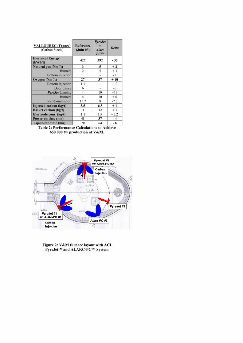
VALLOUREC (France) (Carbon Steels)
Reference (Juin 03)
PyreJet+
Alarc PC™
Delta
Electrical Energy (kWh/t) 427 392 - 35
Natural gas (Nm3/t) 3 5 + 2 Burners 2 5 + 3
Bottom injection 1 - - 1 Oxygen (Nm3/t) 27 37 + 10
Bottom injection 1.3 - -1.3 Door Lance 6 - -6
PyreJet Lancing - 19 +19 Burners 4 10 + 6
Post-Combustion 15.7 8 -7.7 Injected carbon (kg/t) 5,5 6,5 + 1 Basket carbon (kg/t) 11 12 + 1 Electrode cons. (kg/t) 2.1 1,9 - 0.2 Power-on time (mn) 41 37 - 4 Tap-to-tap time (mn) 70 64 - 6
Table 2: Performance Calculations to Achieve 650 000 t/y production at V&M.
Figure 2: V&M furnace layout with ACI PyreJet™ and ALARC-PC™ System

The furnace configuration chosen to achieve these goals is shown in Figure 2. Three PyreJet™ burners and three ALARC-PC™ injectors were installed on the V & M furnace. To save space, two Dragon Panels™ were installed (PyreJets #1 and #2) so that both post-combustion and supersonic lancing could be achieved at the same location. PyreJet #3 was mounted in the EBT area. Therefore, ALARC-PC injector #3 had to be mounted separately from the PyreJet™ burner (see Figure 2). Due to concerns from V&M personnel about steel contacting the Dragon™ Panel, the panels were mounted approximately 200 mm higher than the “split” line of the furnace as a precaution with the intention of eventually lowering them eventually when an improved level of training with the new operation was achieved. The height of the refractory was increased to reach the bottom of the Dragon Panel.
Figure 3, Figure 4 and
Figure 4: PyreJet #3 mounting in EBT
Figure 5 illustrate the mounting of Dragon Panel (with PyreJet and ALARC-PC), the EBT PyreJet and ALARC-PC # 3, respectively at V&M.
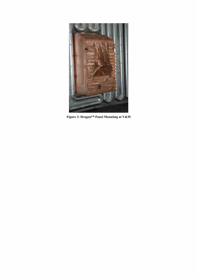
Figure 3: Dragon™ Panel Mounting at V&M
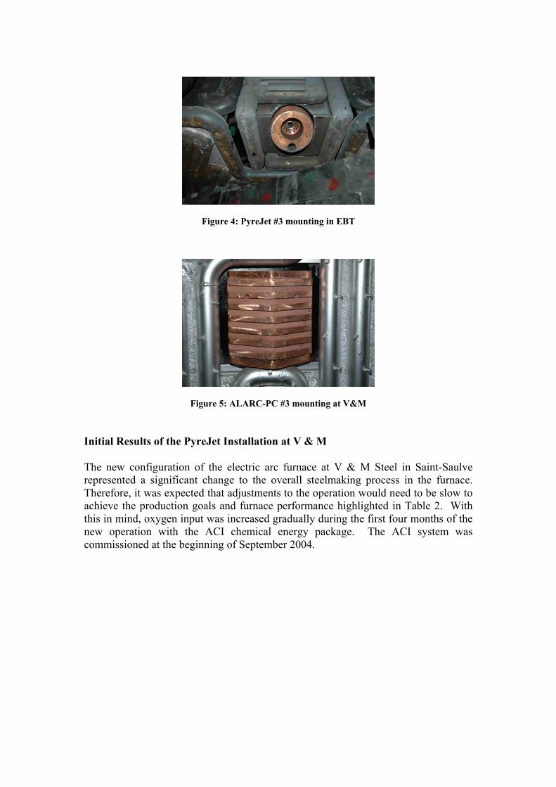
Figure 4: PyreJet #3 mounting in EBT
Figure 5: ALARC-PC #3 mounting at V&M
Initial Results of the PyreJet Installation at V & M The new configuration of the electric arc furnace at V & M Steel in Saint-Saulve represented a significant change to the overall steelmaking process in the furnace. Therefore, it was expected that adjustments to the operation would need to be slow to achieve the production goals and furnace performance highlighted in Table 2. With this in mind, oxygen input was increased gradually during the first four months of the new operation with the ACI chemical energy package. The ACI system was commissioned at the beginning of September 2004.
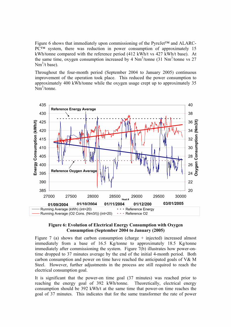
Figure 6 shows that immediately upon commissioning of the PyreJet™ and ALARC-PC™ system, there was reduction in power consumption of approximately 15 kWh/tonne compared with the reference period (412 kWh/t vs 427 kWh/t base). At the same time, oxygen consumption increased by 4 Nm3/tonne (31 Nm3/tonne vs 27 Nm3/t base).
Throughout the four-month period (September 2004 to January 2005) continuous improvement of the operation took place. This reduced the power consumption to approximately 400 kWh/tonne while the oxygen usage crept up to approximately 35 Nm3/tonne.
385
390
395
400
405
410
415
420
425
430
435
27000 27500 28000 28500 29000 29500 30000Heat #
Ener
gy C
onsu
mpt
ion
(kW
h/t)
20
22
24
26
28
30
32
34
36
38
40
Oxy
gen
Con
sum
ptio
n (N
m3/
t)
Running Average (kWh) (int=20) Reference Energy Running Average (O2 Cons. (Nm3/t)) (int=20) Reference O2
01/09/2004 01/10/2004 01/11/2004 01/12/200 03/01/2005
Reference Energy Average
Reference Oxygen Average
Figure 6: Evolution of Electrical Energy Consumption with Oxygen Consumption (September 2004 to January (2005)
Figure 7 (a) shows that carbon consumption (charge + injected) increased almost immediately from a base of 16.5 Kg/tonne to approximately 18.5 Kg/tonne immediately after commissioning the system. Figure 7(b) illustrates how power-on-time dropped to 37 minutes average by the end of the initial 4-month period. Both carbon consumption and power on time have reached the anticipated goals of V& M Steel. However, further adjustments in the process are still required to reach the electrical consumption goal.
It is significant that the power-on time goal (37 minutes) was reached prior to reaching the energy goal of 392 kWh/tonne. Theoretically, electrical energy consumption should be 392 kWh/t at the same time that power-on time reaches the goal of 37 minutes. This indicates that for the same transformer the rate of power
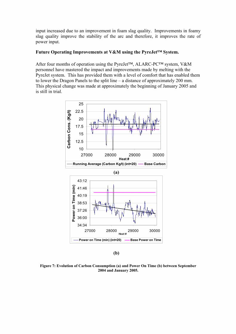
input increased due to an improvement in foam slag quality. Improvements in foamy slag quality improve the stability of the arc and therefore, it improves the rate of power input.
Future Operating Improvements at V&M using the PyreJet™ System. After four months of operation using the PyreJet™, ALARC-PC™ system, V&M personnel have mastered the impact and improvements made by melting with the PyreJet system. This has provided them with a level of comfort that has enabled them to lower the Dragon Panels to the split line – a distance of approximately 200 mm. This physical change was made at approximately the beginning of January 2005 and is still in trial.
10
12.5
15
17.5
20
22.5
25
27000 28000 29000 30000Heat #
Car
bon
Con
s. (K
g/t)
Running Average (Carbon Kg/t) (int=20) Base Carbon
(a)
34:34
36:00
37:26
38:53
40:19
41:46
43:12
27000 28000 29000 30000Heat #
Pow
er o
n Ti
me
(min
)
Power on Time (min) (int=20) Base Power on Time
(b)
Figure 7: Evolution of Carbon Consumption (a) and Power On Time (b) between September
2004 and January 2005.
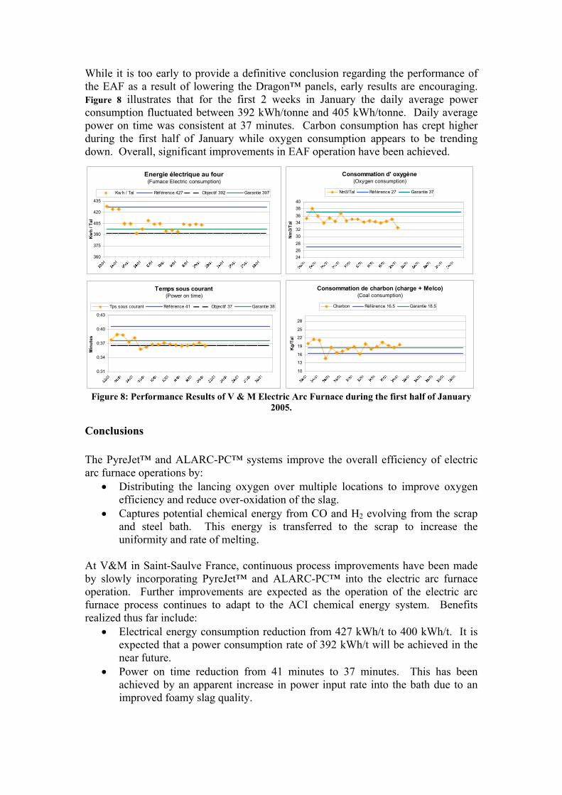
While it is too early to provide a definitive conclusion regarding the performance of the EAF as a result of lowering the Dragon™ panels, early results are encouraging. Figure 8 illustrates that for the first 2 weeks in January the daily average power consumption fluctuated between 392 kWh/tonne and 405 kWh/tonne. Daily average power on time was consistent at 37 minutes. Carbon consumption has crept higher during the first half of January while oxygen consumption appears to be trending down. Overall, significant improvements in EAF operation have been achieved.
Figure 8: Performance Results of V & M Electric Arc Furnace during the first half of January 2005.
Conclusions The PyreJet™ and ALARC-PC™ systems improve the overall efficiency of electric arc furnace operations by:
• Distributing the lancing oxygen over multiple locations to improve oxygen efficiency and reduce over-oxidation of the slag.
• Captures potential chemical energy from CO and H2 evolving from the scrap and steel bath. This energy is transferred to the scrap to increase the uniformity and rate of melting.
At V&M in Saint-Saulve France, continuous process improvements have been made by slowly incorporating PyreJet™ and ALARC-PC™ into the electric arc furnace operation. Further improvements are expected as the operation of the electric arc furnace process continues to adapt to the ACI chemical energy system. Benefits realized thus far include:
• Electrical energy consumption reduction from 427 kWh/t to 400 kWh/t. It is expected that a power consumption rate of 392 kWh/t will be achieved in the near future.
• Power on time reduction from 41 minutes to 37 minutes. This has been achieved by an apparent increase in power input rate into the bath due to an improved foamy slag quality.
Energie électrique au four(Furnace Electric consumption)
360
375
390
405
420
435
Kw
h / T
al
Kw h / Tal Référence 427 Objectif 392 Garantie 397
Temps sous courant(Power on time)
0:31
0:34
0:37
0:40
0:43
Min
utes
Tps sous courant Référence 41 Objectif 37 Garantie 38
Consommation d' oxygène(Oxygen consumption)
242628303234363840
Nm
3/Ta
l
Nm3/Tal Référence 27 Garantie 37
Consommation de charbon (charge + Melco)(Coal consumption)
10
13
16
19
22
25
28
Kg/
Tal
Charbon Référence 16.5 Garantie 18.5
References (1) US Patent 4,622,007 Variable Heat generating method and apparatus. (2) US Patent 5,599,375 Method for electric steelmaking. (3) G. Moraes, “Implementation of PyreJetTM technology in Electric Arc Furnaces at Siderurgica Barra Mansa” 60 EAF Conference, San Antonio, USA, November 2002. (4) B. Allemand, “Theoretical and Experimental Study of Supersonic Oxygen Jets – Industrial Application in EAF”, 58 EAF Conference, Orlando, USA, November 2000. (5) M. Grant, “Principles and Strategy of EAF Post – Combustion”, 58 EAF Conference, Orlando, USA, November 2000. (6) S. Jepson, “Chemical Energy in the EAF: Benefits and Limitations”, 58 EAF Conference, Orlando, USA, November 2000. (7) N. Perrin, “Industrial Use of ALARC-PCTM Post – Combustion Technology Worldwide”, 5th European Electric Steel Conference, Paris, France, June 1995.