blind path obstacle detector using smartphone camera … · blind path obstacle detector using...
TRANSCRIPT
Proceedings of 1st International Conference on Technology and Innovation in Sports, Health and Wellbeing (TISHW 2016)
Blind Path Obstacle Detector using SmartphoneCamera and Line Laser Emitter
Rimon Saffoury*, Peter Blank*, Julian Sessner**, Benjamin H. Groh*, Christine F. Martindale*, Eva Dorschky*,Joerg Franke** and Bjoern M. Eskofier*
*Digital Sports Group, Pattern Recognition Lab, Department of Computer Science**Institute for Factory Automation and Production Systems
Friedrich-Alexander University Erlangen-Nurnberg (FAU), Erlangen, GermanyCorresponding author: [email protected]
Abstract—Visually impaired people find navigating withinunfamiliar environments challenging. Many smart systems havebeen proposed to help blind people in these difficult, oftendangerous, situations. However, some of them are uncomfortable,difficult to obtain or simply too expensive. In this paper, alow-cost wearable system for visually impaired people wasimplemented which allows them to detect and locate obstaclesin their locality. The proposed system consists of two mainhardware components, a laser pointer ($12) and an android smartphone, making our system relatively cheap and accessible. Thecollision avoidance algorithm uses image processing to measuredistances to objects in the environment. This is based on laserlight triangulation. This obstacle detection is enhanced by edgedetection within the captured image. An additional feature of thesystem is to recognize and warn the user when stairs are presentin the camera’s field of view. Obstacles are brought to the user’sattention using an acoustic signal. Our system was shown to berobust, with only 5% false alarm rate and a sensitivity of 90%for 1 cm wide obstacles.
I. INTRODUCTION
According to the World Health Organization (WHO), 2851
million people are estimated to be visually impaired world-wide: 39 million are blind and 246 million have low vision [1].Recognizing dynamic and static obstacles is a basic problemfor visually impaired people, since most of navigational infor-mation are gathered through the visual perception [2]. As aresult, blind people usually rely on other sensory informationin order to avoid obstacles and to navigate [3]. For example,the motion of dynamic obstacles generates noise allowing vi-sually impaired people to determine the approximate positionusing their auditory senses. The additional use of tactile sensesis required for precise obstacle localization. For this purpose awhite cane is commonly used by blind people [4], which hastwo main disadvantages. It is relatively short and the detectionoccurs only by making contact with the obstacle which couldsometimes might be dangerous. Another popular navigationtool for visually impaired individuals is a guide dog. Comparedto white canes, dog guides are able to detect obstacles as wellas steering around them, however they are expensive and onlyhave a very limited working life [5].
1Updated August 2014.
However, many obstacle detection and avoidance systemshave been proposed during the last decade to help blindpeople navigate in known or unknown, indoor and outdoorenvironments. This navigation can primarily be categorizedas vision replacement, vision enhancement and vision sub-stitution [6]. Vision replacement systems provide the visualcortex of the human brain with the necessary informationeither directly or via the optic nerve. Vision enhancement andvision substitution systems have similar working principleswith regard to environment detection process, however, eachprovides the environmental information differently. Visionenhancement presents the information in a visual manner,whereas vision substitution typically uses tactual or auditoryperception or a combination of the two.
Finding obstacle-free pathways via vision substitution canbe further subcategorized into ETAs (Electronic Travel Aids),EOAs (Electronic Orientation Aids) and PLDs (Position Lo-cator Devices). For navigational aid, ETA devices usually usecamera and sonar sensors, EOA devices RFID (Radio Fre-quency Identification) systems and PLD devices GPS (GlobalPositioning Systems) navigational technology. Balachandran etal. [7] proposed a GPS based device where a DGPS (Differ-ential Global Positioning System) was used which providedmore precise user localization and thus better navigation.Tandon et al. [8] applied passive RFID tags for giving locationinformation to users. A passive tag can be embedded in manyplaces, as an internal energy source is not required.
In order to increase the environmental obstacle detectionrange, the use of image or sonars sensors is essential. Bousbia-Salah et al. [9] used two ultrasonic sensors mounted on theuser’s shoulders to provide real-time information about theobstacle distance, whereas Berning et al. [10] placed an arrayof ultrasonic sensors on the head enabling 360 degree distancecalculation. The combination of RFID tags and ultrasonicsensors was proposed by Sanchez et al. [11], which allowedthem to achieve more confident user navigation. The greatestdisadvantage of ultrasonic based systems, compared to camerabased systems, is the low angular resolution due to thewide beam angle [12]. Furthermore, a precise estimation ofdistances to large obstacles cannot be calculated [13]. Owayjanet al. [12] and Rodrıguez et al. [14] developed a camera based
978-1-5090-5727-6/16/$31.00 c©2016 IEEE
Proceedings of 1st International Conference on Technology and Innovation in Sports, Health and Wellbeing (TISHW 2016)
navigation system, which provides the distance to obstaclesusing a disparity map computed using either Microsoft Kinector a stereo camera. To support visual impaired individualsduring sportive activities like jogging, Ramer et al. [15] useda 3D camera to navigate the athlete on tartan tracks. Inorder to achieve that, they took advantage of fixed markson the tartan track. This kind of system is limited to specialenvironments. In general, such systems are computationallydemanding making the device too large for good wearability,due to the large processing unit required.
A relatively low computational effort camera based ap-proach for computing the distance between user and obstacleis the laser rangefinder [16]. This method is based on lasertriangulation, thus, the laser light must be detected first. Accu-rate laser light recognition is crucial for distance measurement.Chmelar et al. [17] proposed a laser line detection algorithmbased on RGB color segmentation, where a different thresholdvalue for every color channel. In a later work, Chmelar etal. [18] used GMM (Gaussian Mixture Model) for detectingthe laser line. Yang et al. [19] tried to extract the laserline using the minimum entropy models. Nam Ta et al. [20]segmented the laser line using the advantages of YCbCr andHSI color spaces.
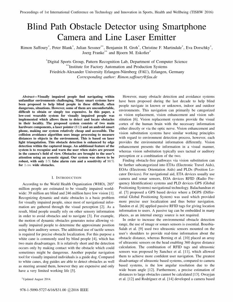
All aforementioned methods detected laser scan lines onlyin environments with low level noises. In this work, we in-vestigate a new approach for obstacle detection and avoidancesystem for blind people based on laser range finder, which isable to detect obstacles within environments with relativelyhigh level noises. The laser line extraction is achieved by atemplate matching algorithm. We evaluate the proposed systemwith respect to reliability and effectiveness. In order to validateour idea, we have built a proof of concept, shown in Figure 1that can be classified as ETA.
Fig. 1: The optical based laser rangefinder which is composedby two main elements: an Android device and a laser lineemitter placed on the bottom of the device and aligned exactlyperpendicular to the smart phone camera.
II. METHODS
A. Data acquisition
Two main elements were used for implementing the pro-posed system: a Samsung Galaxy S5 running Android 4.0 IceCream Sandwich and a laser module 2.The laser had a lineshape, an output power of 5mW , a 650nm wavelength anda working voltage of 3− 12V . The chosen laser was a class1 laser, therefore not harmful. For acquiring the images, theinbuilt smart phone camera was used, which had a frame rateof 10 fps and a frame size of 640 × 360 pixels. Processingthe images was done locally, on the smart phone, and wasimplemented using the OpenCV library [21]. Feedback to theuser was provided using the internal smart phone speakers.
B. Obstacle detection and avoidance system
The implemented algorithm was split in four parts, as shownin Figure 2. In the laser light detection step, the projectedlaser scan line was extracted from the captured image. Usingthe pixel position of the extracted laser line on the imageplane and a calibrated rangefinder system, the range data toobstacles was calculated. In the next step, the intensity of theextracted laser line was analyzed allowing detection of smallerobstacles, obstacles with 1 − 100 cm width. Finally, instantacoustic feedback warned the user of a pending collision withboth small and large obstacles.
Laser light recognition
In this paper, obstacle detection accuracy is highly depen-dent on the laser light recognition. Detecting the laser scanline also depends on the noise within the acquired image. Fordetecting the laser scan line, a template matching algorithmwas used. The first step in the algorithm was the storage ofa laser light template. Due to the high computational cost ofthe template matching algorithm in the RGB color space, a1D pixel row was chosen as a template. By using a smallertemplate, the computation time will considerably increaseachieving only a non real-time result. The chosen templateis shown in Figure 3a at the top of the image. Afterwardsthe template image was compared to the captured image bysliding it and calculating its match metric calculated using thenormalized sum of squared differences (Equation 1).
R′(x, y) =R(x, y)
K(x, y)(1)
With:
R(x, y) =∑x′,y′
(T (x′, y′)− I(x+ x′, y + y′))2
K(x, y) =
√∑x′,y′
T (x′, y′)2 ·∑x′,y′
I(x+ x′, y + y′)2
The variables x and y denote the current pixel position in thecaptured image. x′ and y′ denote the current pixel positionin the template image. The function I stands for the captured
2Laser type: LFL650-5-12(9x20)60
Proceedings of 1st International Conference on Technology and Innovation in Sports, Health and Wellbeing (TISHW 2016)
Acquire Image
Laser light recognition(1)
Distance measurement(2)
Small obstacles detection(3)
Template matching
Triangulation basedlaser range finder
RGB to gray
Box filter
Prewitt operator
Thresholding
Instant feedback(4)
Extracted laser line
Distance to extracted line
Edges on extracted line
Proposed system
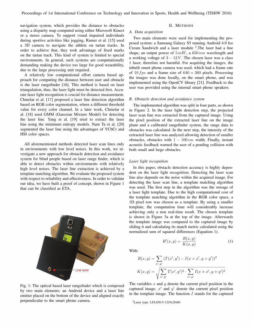
Fig. 2: Algorithm pipeline for the proposed obstacle detectionand avoidance system. Firstly, the laser light was extractedusing a template matching algorithm. The distance to obstacleswas calculated using a triangulation based laser range findersystem. Furthermore, a box filter followed by the prewittoperator was applied on the extracted laser line. Magnitude ofthe prewitt operator was set in order to allow small obstacledetection. Finally, when a user is heading towards an obstacle,the user was notified acoustically.
image (Figure 3a), T for the template image (top of Figure 3a).R′(x, y) represents result image at position x and y, where thefunction R(x, y) the sum of squared differences and K(x, y)the normalization factor.
The greater the pixel match between template image andcaptured image with respect to their intensity values, the lowerthe intensity value R′(x, y) meaning pixel is darker on theresult image. Thus, the lowest intensity value on the image
(a) (b)
Fig. 3: (a) captured image, where in the middle of the imagethe emitted laser scan line and at the top of the image thechosen template are shown (b) result image after applyingtemplate matching weighted with the normalized sum ofsquared differences, where the blue line denotes the locationof the highest probability of a match
plane was extracted, which indicated the highest probabilityof a match (blue line on Figure 3b).
Distance measurement
After detecting the laser light, the distance between thelaser emitter and the laser scan line was determined usinga triangulation technique through a calibrated rangefindersystem (Figure 4).
Using the static offset h between the smart phone camera,the laser emitter and the dynamic angle α between the centerof focal plane and the projection line, the distance to the targetD was calculated as follows [22]:
D =h
tanα. (2)
The angle α is a dynamic variable and is given by
α = ρ ·R+ rad (3)
where:
ρ : number of pixel from the center of focal planeR : radians per pixel pitch
rad : radian compensation for alignment error
The pixel number from the center of focal plane ρ wascalculated in the previous subsection through the position ofthe line which was extracted using the template matchingalgorithm. For determining R and rad a system calibrationwas performed. In order to calibrate the system, Equation (2)was rewritten as
αreference = arctan(h
Dreference), (4)
where Dreference is a real measured distance and αreference
its corresponding angle. After measuring 15 real distances and
Proceedings of 1st International Conference on Technology and Innovation in Sports, Health and Wellbeing (TISHW 2016)
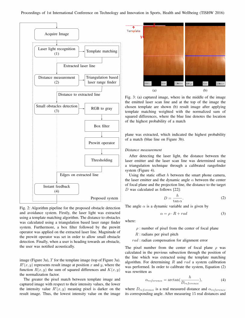
Fig. 4: Principle of laser rangefinder system based on triangu-lation technique. The variable D denotes the distance betweenlaser emitter and target, h the offset between smart phonecamera and laser emitter, ρ pixel position of the image plane,α the angle between center of focal plane and projection line
200 250 300 350
0.2
0.4
0.6
ρ (laser position)
αreference
(mea
sure
dan
gle)
Measured distanceDistance approximation
Fig. 5: Example of measured data with its regression line,which approximates the equation for the angle α (Equa-tion (3)) with R ≈ 352.248·10−3 and rad ≈ −588.205·10−1.ρ denotes the current pixel position on the image plane,while αreference represents the real angle measured usingEquation (4).
their corresponding angles, the angle α (Equation (3)) wasapproximated by the regression line of the real measured data,where the slope-intercept corresponds to the radians per pixelpitch R and the y-intercept to the radian compensation foralignment error rad (Figure 5).
In this way, the calibrated range finder system was ableto calculate the distance between the laser emitter and itsprojected laser light.
0 200 400 600 800 1,000
0
50
100
150
Distance (pixels)
Inte
nsity
valu
e
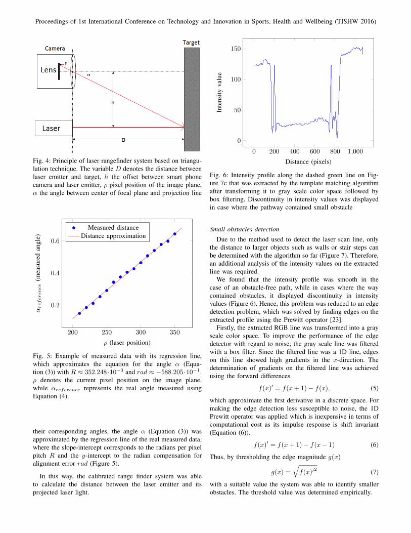
Fig. 6: Intensity profile along the dashed green line on Fig-ure 7c that was extracted by the template matching algorithmafter transforming it to gray scale color space followed bybox filtering. Discontinuity in intensity values was displayedin case where the pathway contained small obstacle
Small obstacles detection
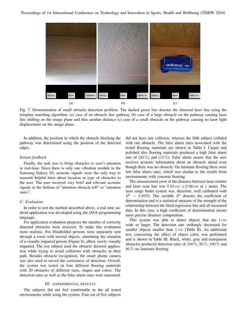
Due to the method used to detect the laser scan line, onlythe distance to larger objects such as walls or stair steps canbe determined with the algorithm so far (Figure 7). Therefore,an additional analysis of the intensity values on the extractedline was required.
We found that the intensity profile was smooth in thecase of an obstacle-free path, while in cases where the waycontained obstacles, it displayed discontinuity in intensityvalues (Figure 6). Hence, this problem was reduced to an edgedetection problem, which was solved by finding edges on theextracted profile using the Prewitt operator [23].
Firstly, the extracted RGB line was transformed into a grayscale color space. To improve the performance of the edgedetector with regard to noise, the gray scale line was filteredwith a box filter. Since the filtered line was a 1D line, edgeson this line showed high gradients in the x-direction. Thedetermination of gradients on the filtered line was achievedusing the forward differences
f(x)′ = f(x+ 1)− f(x), (5)
which approximate the first derivative in a discrete space. Formaking the edge detection less susceptible to noise, the 1DPrewitt operator was applied which is inexpensive in terms ofcomputational cost as its impulse response is shift invariant(Equation (6)).
f(x)′ = f(x+ 1)− f(x− 1) (6)
Thus, by thresholding the edge magnitude g(x)
g(x) =
√f(x)′
2 (7)
with a suitable value the system was able to identify smallerobstacles. The threshold value was determined empirically.
Proceedings of 1st International Conference on Technology and Innovation in Sports, Health and Wellbeing (TISHW 2016)
(a) (b) (c)
Fig. 7: Demonstration of small obstacle detection problem. The dashed green line denotes the detected laser line using thetemplate matching algorithm. (a) case of an obstacle free pathway (b) case of a large obstacle on the pathway causing laserline shifting on the image plane and thus another distance (c) case of a small obstacle on the pathway causing no laser lightdisplacement on the image plane.
In addition, the position in which the obstacle blocking thepathway was determined using the position of the detectededges.
Instant feedbackFinally, the task was to bring obstacles to user’s attention
in real-time. Since there is only one vibration module in theSamsung Galaxy S5, acoustic signals were the only way totransmit helpful hints about location or type of obstacles tothe user. The user received very brief and relevant acousticsignals in the fashion of ”attention obstacle left” or ”attentionstairs”.
C. EvaluationIn order to test the method described above, a real time an-
droid application was developed using the JAVA programminglanguage.
For application evaluation purposes the number of correctlydetected obstacles were assessed. To make this evaluationmore realistic, five blindfolded persons were separately sentthrough a room with several objects, simulating the situationof a visually impaired person (Figure 8), albeit, newly visuallyimpaired. The test subject used the obstacle detector applica-tion while trying to avoid collisions with obstacles in theirpath. Besides obstacle recognition, the smart phone camerawas also used to record the correctness of detection. Overall,the system was tested on four different flooring materialswith 20 obstacles of different sizes, shapes and colors. Thedetection rates as well as the false alarm rates were measured.
III. EXPERIMENTAL RESULTS
The subjects did not feel comfortable in the all testedenvironments while using the system. Four out of five subjects
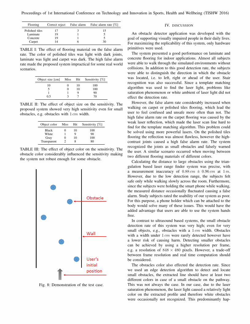
did not have any collision, whereas the fifth subject collidedwith one obstacle. The false alarm rates associated with thetested flooring materials are shown in Table I. Carpet andpolished tiles flooring materials produced a high false alarmrate of (30%) and (15%). False alarm means that the userreceives acoustic information about an obstacle ahead eventhough there was no obstacle. On laminate flooring there werelow false alarm rates, which was similar to the results fromenvironments with concrete flooring.
The measurement error of the distance between laser emitterand laser scan line was 0.88 cm ± 0.96 cm at 1 meter. Thelaser range finder system was, therefore, well calibrated withR2 = 0.9976. The variable R2 denotes the coefficient ofdetermination and is a statistical measure of the strength of therelationship between the fitted regression line and all measureddata. In this case, a high coefficient of determination meansmore precise distance computation.
This system was able to detect objects that are 1 cmwide or larger. The detection rate strikingly decreased forsmaller objects smaller than 1 cm (Table II). An additionaltest, concerning the effect of object color, was performedand is shown in Table III. Black, white, gray and transparentobstacles produced detection rates of 100%, 90%, 100% and80% on laminate flooring.
Proceedings of 1st International Conference on Technology and Innovation in Sports, Health and Wellbeing (TISHW 2016)
Flooring Correct reject False alarm False alarm rate [%]
Polished tiles 17 3 15Laminate 19 1 5Concrete 19 1 5Carpet 14 6 30
TABLE I: The effect of flooring material on the false alarmrate. The color of polished tiles was light with dark joints,laminate was light and carpet was dark. The high false alarmrate made the proposed system impractical for some real worldscenarios.
Object size [cm] Miss Hit Sensitivity [%]
10 0 10 1005 0 10 1001 1 9 90
0.5 3 7 70
TABLE II: The effect of object size on the sensitivity. Theproposed system showed very high sensitivity even for smallobstacles, e.g. obstacles with 1 cm width.
Object color Miss Hit Sensitivity [%]
Black 0 10 100White 1 9 90Gray 0 10 100
Transparent 2 8 80
TABLE III: The effect of object color on the sensitivity. Theobstacle color considerably influenced the sensitivity makingthe system not robust enough for some obstacle.
Fig. 8: Demonstration of the test case.
IV. DISCUSSION
An obstacle detector application was developed with thegoal of supporting visually impaired people in their daily lives.For maximizing the replicability of this system, only hardwareprimitives were used.
The system presented a good performance on laminate andconcrete flooring for indoor applications. Almost all subjectswere able to walk through the simulated environments withoutcollisions. In addition to this good detection rate, the subjectswere able to distinguish the direction in which the obstaclewas located, i.e. to left, right or ahead of the user. Stairrecognition was also successful. Since a template matchingalgorithm was used to find the laser light, problems likesaturation phenomenon or white ambient of laser light did noteffect the detection rate.
However, the false alarm rate considerably increased whenwalking on carpet or polished tiles flooring, which lead theuser to feel confused and unsafe more often than not. Thehigh false alarm rate on the carpet flooring was caused by theweak laser reflection, which made the laser scan line hard tofind for the template matching algorithm. This problem couldbe solved using more powerful lasers. On the polished tilesflooring the reflection was almost flawless, however the high-contrast joints caused a high false alarm rate. The systemrecognized the joints as small obstacles and falsely warnedthe user. A similar scenario occurred when moving betweentwo different flooring materials of different colors.
Calculating the distance to large obstacles using the trian-gulation based laser range finder system was precise, witha measurement inaccuracy of 0.88 cm ± 0.96 cm at 1m.However, due to the low detection range, the subjects feltsafe only while walking slowly across the room. Furthermore,since the subjects were holding the smart phone while walking,the measured distance occasionally fluctuated causing a falsealarm. Study subjects rated the usability of our system as poor.For this purpose, a phone holder which can be attached to thebody would solve many of these issues. This would have theadded advantage that users are able to use the system handsfree.
In contrast to ultrasound based systems, the small obstacledetection rate of this system was very high; even for verysmall objects, e.g., obstacles with a 1 cm width. Obstacleswith a width under 1 cm were rarely detected however havea lower risk of causing harm. Detecting smaller obstaclescan be achieved by using a higher resolution per frame,e.g. a resolution of 848 × 480 pixels. However, a trade-offbetween frame resolution and real time computation shouldbe considered.
The obstacles color also effected the detection rate. Sincewe used an edge detection algorithm to detect and locatesmall obstacles, the extracted line should have at least twodifferent colors in case of a small obstacle on the pathway.This was not always the case. In our case, due to the lasersaturation phenomenon, the laser light caused a relatively lightcolor on the extracted profile and therefore white obstacleswere occasionally not recognized. This predominantly hap-
Proceedings of 1st International Conference on Technology and Innovation in Sports, Health and Wellbeing (TISHW 2016)
pened while trying to detect white obstacles on light coloredflooring materials. Furthermore, the recognition of transparentobstacles was slightly worse than white obstacles. The fact,that transparent medium normally diffracts the incident lightproducing a displacement of the laser scan line resulting in anedge on the extracted line, and thus an obstacle recognition.
The method of information transfer to the user about ob-stacles was efficient and useful as almost all subjects did notcollide with an obstacle. However, some of them knew imme-diately how to handle the appearing obstacle, whereas otherfirstly needed to rethink. Nonetheless, an acoustic signal asfeedback may reduce the natural use of the visually impairedperson’s sense of hearing. Transmitting the environmentalinformation, about obstacles, by other means should also beexplored.
V. SUMMARY AND OUTLOOK
In this paper, a system which allows visually impaired indi-viduals to detect and avoid obstacles was implemented as anandroid application. The obstacle detector application providesa high detection rate of up to 100% on selected environments.The main limitations of this system were flooring materialswhich have extremely weak light reflection and obstacles witha color similar to the laser light.
In order to improve the robustness of this system a powerfulline laser module could be used, allowing an improved laserline detection. A cross laser module, as opposed to a line lasermodule, should be investigated. The proposed system couldbe also applied to smart phones that have two back cameras,thus enabling us to additionally measure a depth map of theenvironment. This application could be enhanced with GPSinformation, a common feature to most smart phones.
Additionally, if the processing performance is improved itwill allow the processing of a higher frame resolution, andthus allow more precise acquisition of the local environment.This can be achieved by limiting the search of the templatematching algorithm, since the laser light is moving in a pre-defined range. Furthermore, the template matching algorithmsearch can be terminated after obtaining a certain thresholdwith respect to similarity.
VI. ACKNOWLEDGMENT
Special thanks goes to all test persons for their supportin this project. This work was supported by the BavarianMinistry for Economic Affairs, Infrastructure, Transport andTechnology and the Embedded Systems Initiative (ESI).
REFERENCES
[1] World Health Organization (WHO). Visual impairment and blindness.http://www.who.int/mediacentre/factsheets/fs282/en/, 2014. Last visited:15.03.2016.
[2] M.Angeles Espinosa, Simon Ungar, Esperanza Ochata, Mark Blades,and Christopher Spencer. Comparing methods for introducing blind andvisually impaired people to unfamiliar urban environments. Journal ofEnvironmental Psychology, 18(3):277 – 287, 1998.
[3] William Henry Jacobson. The art and science of teaching orientationand mobility to persons with visual impairments. American Foundationfor the Blind, 1993.
[4] Vincent Levesque. Blindness, technology and haptics. Center forIntelligent Machines, pages 19–21, 2005.
[5] Yunqing Wang and Katherine J Kuchenbecker. Halo: Haptic alerts forlow-hanging obstacles in white cane navigation. In Haptics Symposium(HAPTICS), 2012 IEEE, pages 527–532. IEEE, 2012.
[6] Dimitrios Dakopoulos and Nikolaos G Bourbakis. Wearable obstacleavoidance electronic travel aids for blind: a survey. IEEE Transactionson Systems, Man, and Cybernetics, Part C: Applications and Reviews,40(1):25–35, 2010.
[7] Wamadeva Balachandran, Franjo Cecelja, and Piotr Ptasinski. A gpsbased navigation aid for the blind. In 17th International Conference onApplied Electromagnetics and Communications (ICECom), pages 34–36.IEEE, 2003.
[8] Kushagra Tandon, Tanuja Pande, Mohammad Adil, Govind Dubey,and Amit Kumar. A blind navigation system using rfid for indoorenvironments. International Journal of Computer Systems, 2(4):115 –118, 2015.
[9] Mounir Bousbia-Salah, Maamar Bettayeb, and Allal Larbi. A navigationaid for blind people. Journal of Intelligent & Robotic Systems, 64(3-4):387–400, 2011.
[10] Matthias Berning, Florian Braun, Till Riedel, and Michael Beigl. Prox-imityhat: A head-worn system for subtle sensory augmentation withtactile stimulation. In Proceedings of the 2015 ACM InternationalSymposium on Wearable Computers, ISWC ’15, pages 31–38, New York,NY, USA, 2015. ACM.
[11] Jayron Sanchez, Analyn Yumang, and Felicito Caluyo. Rfid basedindoor navigation with obstacle detection based on a* algorithm for thevisually impaired. International Journal of Information and ElectronicsEngineering, 5(6):428, 2015.
[12] Michel Owayjan, Ali Hayek, Hassan Nassrallah, and Mohammad Eldor.Smart assistive navigation system for blind and visually impairedindividuals. In International Conference on Advances in BiomedicalEngineering (ICABME), pages 162–165. IEEE, 2015.
[13] Ming Yang, SL Hill, and JO Gray. Localization of plane reflectors usinga wide-beamwidth ultrasound transducer arrangement. IEEE Transac-tions on Instrumentation and Measurement, 46(3):711–716, 1997.
[14] Alberto Rodrıguez, J Javier Yebes, Pablo F Alcantarilla, Luis M Bergasa,Javier Almazan, and Andres Cela. Assisting the visually impaired:obstacle detection and warning system by acoustic feedback. Sensors,12(12):17476–17496, 2012.
[15] C. Ramer, C. Ziegler, S. Reitelshofer, and J. Franke. Sensor-guidedjogging for visually impaired. In 5th IEEE RAS EMBS InternationalConference on Biomedical Robotics and Biomechatronics,, pages 467–472, Aug 2014.
[16] Zhiming Ji and Ming-Chuan Leu. Design of optical triangulationdevices. Optics & Laser Technology, 21(5):339–341, 1989.
[17] Pavel Chmelar and Martin Dobrovolny. The laser line detection forautonomous mapping based on color segmentation. International Jour-nal of Mathematical, Computational, Physical, Electrical and ComputerEngineering, 7(12):1654 – 1658, 2013.
[18] Pavel Chmelar, Ladislav Beran, and Nataliia Kudriavtseva. The lasercolor detection for 3d range scanning using gaussian mixture model. InRadioelektronika (RADIOELEKTRONIKA), 25th International Confer-ence, pages 248–253. IEEE, 2015.
[19] Wei Yang, Liguo Zhang, Wei Ke, Ce Li, and Jianbin Jiao. Minimumentropy models for laser line extraction. In Computer Analysis of Imagesand Patterns, pages 499–506. Springer, 2013.
[20] Hong Nam Ta, Daesik Kim, and Sukhan Lee. A novel laser line detectionalgorithm for robot application. In 11th International Conference onControl, Automation and Systems (ICCAS), pages 361–365. IEEE, 2011.
[21] Open source computer vision (opencv). http://www.opencv.org. Lastvisited: 15.03.2016.
[22] Shahed Shojaeipour, Sallehuddin Mohamed Haris, Ali Shojaeipour,Rassoul Keshvari Shirvan, and Muhammad Khalid Zakaria. Robot pathobstacle locator using webcam and laser emitter. Physics Procedia,5:187–192, 2010.
[23] JMS Prewitt. Picture processing and psychopictorics. Academic Press,New York, 1970.