biomimetic characteristics of an active deployable structure · biomimetic characteristics of an...
TRANSCRIPT
Swiss Federal Institute of Technology
Lausanne
BIOMIMETIC CHARACTERISTICS OF AN ACTIVE
DEPLOYABLE STRUCTURE
Ph.D. Research Proposal
by
Sinan Korkmaz
Jury Members:
Prof. I.F.C. Smith
Prof. T. Keller
Prof. A. Schleiss
2009

2

3
SUMMARY
Biomimetic structures are structures that demonstrate increased functionality through
mimicking qualities of biological organisms. Self-repair and adaptation mechanisms are
examples of biological qualities that can be adapted in structural engineering. Over the last
decades, great strides have been made in advancing theory and practice of active structural
control. However, little scientific progress has been made on biomimetic structures. Advances
in sensor, actuator, and microprocessor technologies provide increasing possibilities for
implementing active control systems in the built environment. Intelligent control
methodologies such as self-diagnosis, self-repair and learning could be integrated into
structural systems to provide innovative solutions. The general goal of this thesis is to study
biomimetic characteristics of an active and deployable tensegrity bridge. Building on previous
research carried out at EPFL, this thesis proposal includes the following objectives: 1) design
an active control system in order to ensure damage tolerance of a deployable tensegrity
pedestrian bridge; 2) extend existing strategies for self-diagnosis of the deployable tensegrity
bridge to avoid ambiguous results; 3) extend existing strategies in order to achieve a more
robust self-repair scheme; 4) develop algorithms that allow the active control system to learn
efficiently using case-based reasoning; 5) validate the methodologies developed with
experiments on a near full-scale (1/3) model. A literature survey of biomimetics, structural
control, tensegrity structures, deployable structures, deployable tensegrity structures, active
tensegrity structures, case-based reasoning, system identification, and multi-objective search
has identified that these objectives are original. Results obtained from the preliminary studies
demonstrate the potential of this research strategy. A research plan containing 19 subtasks that
will be completed by the end of April 2012 leaves sufficient buffer time before the official
end of this Ph.D. research on September 30, 2012.
KEYWORDS
Biomimetics, active control, active structures, self-diagnosis, self-repair, learning, damage
tolerance, deployable structures, tensegrity structures, pedestrian bridges, stochastic search,

4
TABLE OF CONTENTS
1. Introduction
1.1 Motivation
1.2 Objectives
2. State of the Art
2.1 Biomimetics
2.2 Structural Control
2.3 Tensegrity Structures
2.4 Deployable Structures
2.5 Deployable Tensegrity Structures
2.6 Active Tensegrity Structures
2.7 Case-Based Reasoning
2.8 System Identification
2.9 Multi-Objective Search
3. Relevant Research at IMAC, EPFL
3.1 Active Tensegrity Structures
3.2 Learning
3.3 Multi-Objective Control
3.4 Self-Diagnosis and Self-Repair
4. Preliminary Results
4.1 Need for Active Control In Terms of Damage Tolerance
4.2 Formulation of Optimization Problem
4.3 Case Studies
4.4 Conclusions of the Preliminary Study
4.4.1 Feasibility of Active Control
4.4.2 Serviceability vs. Deployment
4.4.3 X-Cables vs. Layer Cables
4.4.4 Clustering
4.4.5 Influence of Symmetry
4.4.6 Optimization of Actuator Locations

5
5. Research Plan
5.1 Summary of Objectives
5.2 Task Description
6. Importance of This Research
7. Table of Contents of the Thesis
8. Collaboration
9. References

6
1. INTRODUCTION
1.1. Motivation
Application of biological systems to design engineering systems and structures has been
practiced since human-beings understood that nature generates good solutions. The transfer of
knowledge from life forms to synthetic constructs is attractive due to the fact that the living
organisms are optimized and efficient thanks to natural selection. Engineering structure
functionality could thus be increased through mimicking qualities of biological organisms.
Such replication can be achieved by integrating intelligent control methodologies within
active structures. Recent advances in computing, wireless technology, as well as increasing
possibilities for data acquisition and actuation technologies have now provided the enabling
technologies for biomimetic structures and other systems.
There has been a growing amount of research into structural control due to several factors
such as new challenges (e.g. space missions) and damage caused by earthquakes. Aerospace
engineers have used active control in order to make spacecraft and aircraft move within their
environment. In built environments, structural control has been proposed for enhancing safety
of structures under extreme conditions since the last quarter of the 20th century. However,
long-term reliability of control systems has been a matter of controversy in the case of
actively controlled civil structures. Despite the fact that structural control has been applied for
earthquake protection in the US and Japan, where earthquakes are the primary concern, most
engineers believe that active control is not the best way to protect civil engineering structures
against such phenomena due to large return periods and concern related to long-term
reliability of active control systems. Instead, actively controlled structures are more suited to
satisfy serviceability criteria in changing environments. The aim of an intelligent structure is
to enhance the structural performance by sensing the changes in behavior and in loading,
adapting the structure to meet goals, and retrieving past events to improve future performance
(Shea and Smith, 1998). When active control systems are used to satisfy serviceability
criteria, long term reliability of the control system is of less concern than when primary
control objectives are associated with safety criteria (Shea et al., 2002). In this thesis, active
control is used to improve damage tolerance instead of ensuring safety requirements of the
structure. Integrating biomimetic approaches within research into intelligent structures has the
potential to identify efficient solutions through inspiration of solutions from nature.
7
Deployable structures are structures that have the ability to be transformed from a packed up
compact configuration to expanded operational configurations that have safe and serviceable
load carrying capacities. Their ability to change shape is a significant advantage for
transportation and storage. To achieve deployment, deployable structures have active
elements that are usually active only during deployment
A tensegrity system is a system in a stable self-equilibrated state comprising a discontinuous
set of compressed components within a continuum of tensioned components (Motro, 2003).
Tensegrity systems are spatial reticulate systems that have applications in a range of fields
such as aerospace engineering, sculpture, architecture, civil engineering, marine engineering
and biology. Tensegrity structures have several promising properties. A high strength to mass
ratio provides possibility of designing strong and lightweight structures.
Among different traditional approaches, the tensegrity concept is one of the most promising
for active and deployable structures. Being relatively lightweight and flexible, tensegrity
structures need only small amount of energy for shape control. More generally, tensegrities
usually have wide ranges of feasible solutions for control of geometry, stiffness and vibration.
1.2. Objectives
The intention of this thesis is to study biomimetic characteristics of an active deployable
tensegrity structure. The structure will be an actively controlled deployable tensegrity
pedestrian bridge, which is currently being designed in context of another Ph.D. thesis at
IMAC (Rhode-Barbarigos). The active control system will be extended within the scope of
this thesis plan. More specifically, the active control system will be optimized in such a way
that the structure will be damage tolerant during its service life. Building upon the previous
studies conducted at IMAC (Fest, Domer, Adam and Rhode-Barbarigos), the following
objectives are part of this thesis (see Section 5.2 for further details):

8
1. Design an active control system for the purpose of ensuring the damage tolerance of a
deployable tensegrity pedestrian bridge
The deployable bridge already has active elements designed for deployment function
in context of Rhode-Barbarigos’ Ph.D. thesis research at IMAC. New active members
are to be defined in order to satisfy robustness criteria during the service life of the
structure. Optimum locations for actuation means will be determined by studying
damage cases.
2. Extend existing strategies for self-diagnosis of the deployable tensegrity bridge to
avoid ambiguous results:
The active control system of the structure will be capable of identifying excessive
loading and damage in order to switch to self-repair phase. Existing brute-force search
strategies, which are proposed by Adam (2007) for self-diagnosis, will be evaluated
for application to the deployable tensegrity bridge and improved for better search
performance.
3. Extend existing strategies in order to achieve a robust self-repair scheme:
Results of the pilot study will be compared with damage identification and learning
procedure proposed previously. The damage identification and self repair procedures
presented by Adam (2007) will be extended. Clustering techniques will be employed
to ensure an effective use of actuation means. Multi-objective self-repair procedures
will be developed to take into account additional robustness objectives. Robustness of
both the structure and the active control system will be addressed.
4. Design and develop algorithms that allow the active control system to learn, using
CBR by extending previous methods:
Case-based reasoning (CBR) will be used to provide an active control system that can
solve new problems rapidly using the solutions of past problems. Increasing the
number of cases will improve control solution computation time. Focus will be on

9
maintaining the case-based maintenance so that it contains a good distribution of
useful cases, thereby extending previous work.
5. Verify the control system components with experiments on a near full-scale (1/3)
model
The configuration of the control system obtained using computational methods in
mechanics and advanced computing will be verified by experimental results. The
experiments will be carried out on a near full-scale (1/3) model of the structure.
2. STATE OF THE ART
2.1. Biomimetics
Biomimetics is the field of scientific endeavor, which attempts to design systems and
synthesize materials through biomimicry (Ramachandra Rao, 2003). A goal of biomimetics is
to discover enviable qualities and characteristics in biological systems and apply them to
develop solutions in science and engineering. Biomimetics have a large number of potential
applications, ranging from computer systems, aerospace engineering, electronics and robotics
to architecture and marine engineering.
Self reproducing automata were proposed by Von Neumann (1966) as pioneer of bio-inspired
computer systems. Self reproduction and self-repair characteristics of this system is inspired
by biological cells, which can reproduce by cell division (Von Neumann, 1966). Denning
(1976) developed four related architectural principles which can guide construction of error-
tolerant operating systems. Damage detection and correction is elaborated in order to provide
error-tolerant systems (Denning, 1976). Kuc (1993) implemented a sonar-driven robot,
ROBAT, to track an object moving in three dimensions using qualitative interpretation of
sonar signals.
Mange (1997) et al. described a complex system that was inspired by molecular biology and
allowed development of new field-programmable gate arrays endowed with quasi-biological
properties. This kind of computer architecture is useful in environments where human
intervention is necessarily limited, such as nuclear plants and space applications. In this study,

10
self-reproduction (automatic production of one or more copies of the original organism) and
self-repair (automatic repair of one or more faulty cells) were highlighted (Mange et al.,
1997). Sipper (1997) et al. showed that certain properties that are unique to the living world,
such as self-replication, self-repair, and growth, can also be attained in artificial objects
(integrated circuits) by adopting certain features of cellular organization, and by transposing
them to world of integrated circuits on silicon. Mange et al. (1999) presented a silicon-based
artificial cell, followed by a description of mechanisms operating at cellular level: cellular
differentiation, cellular division, regeneration, and replication. They presented also the
composition of the cell as an ensemble of lower-level elements, known as ‘molecules’
(Mange et al., 1999).
Teuscher et al. (2001) introduced bio-inspired computing tissue that constitutes a key concept
for implementation of ‘living’ machines. They studied an error-tolerant BioWall application.
BioWall was a reconfigurable computing tissue that was capable of interacting with its
environment by means of a large number of touch-sensitive elements coupled with a color
display. They stated that biomimetic computer tissues could help human beings understand
natural phenomena, along providing more intelligent machines (Teuscher et al., 2001).
Floreano and Mondada (1998) described a methodology for evolving neurocontrollers of
autonomous mobile robots without human intervention. Sterrit (2005) et al put forward that
autonomic computing is a major strategic and holistic alternative approach to the design of
complex distributed computer systems. Autonomic computing was based on strategies used
by biological systems to successfully deal with similar challenges of complexity, dynamism,
heterogeneity and uncertainty (Sterrit et al., 2005).
In the 19th century, an architecture style called “organic architecture” emerged. Organic
architecture is considered the counter point of rational design, based on modular principles.
Antoni Gaudí, Alvar Alto and Frank Lloyd Wright are considered as the main representatives
of this architectural language. According to organic architecture, constructive ideal evolves
from the human body (Kowaltowski et al., 2007). Anshuman and Kumar (2005) have carried
out a comparative analysis of intelligent building facades and sixteen large media-facades
from a social-psychology perspective. Recently, biomimetic approaches have become very
common in material science applications. Zhou et al. (2007) developed bio-inspired wearable
characteristic surface imitating cuticles of soil animals. Schneider et al. (2009) mimicked
ovipositor of the wood-boring wasp Sirex noctilio for the development of a novel type of

11
neurosurgical probes. Surface texturing and various microstructure geometries were
fabricated and investigated as to their tribological properties during penetration of a probe into
brain tissue (Schneider et al., 2009)
In spite of many applications in several fields, biomimetics applications in civil engineering
need to be identified and realized. Aside from recent work at EPFL (see section 3), no
scientific application of biomimetics on a civil engineering structure has been found in the
literature. Although computer scientists have used biomimetic methods for diverse aims,
experimental and analytic application of such approaches are new to structural engineering.
2.2. Structural Control
Advances in theory and practice of active structural control technology have modified the
general perception about structures. Due to incorporated intelligence, structures become
dynamic objects capable of interacting with complex environments (Shea et al., 2002). Some
space structures are actively controlled to mitigate affect of vibrations and deformations, as
well as to create deployable and variable geometry structures. In civil structures, structural
control has principally focused on improving the overall structural response for primarily
safety and secondarily, serviceability purposes. Serviceability has not been primary concern in
active control investigations until the beginning of the 21st century. Conventionally, structural
control has been carried out by providing a supplementary system that could apply forces to a
structure under loading in order to alleviate external excitations caused by earthquakes or high
winds (Elseaidy et al., 1997).
Structural control systems are categorized as passive, active, hybrid and semi-active (Shea et
al., 2002). In an active control system, an external power source supplies energy to control
actuators that apply forces to the structure in a prescribed manner. The applied force can both
add and dissipate energy from the structure. A function of the response of the system
measured with optical, mechanical, electrical or chemical sensors create the signals sent to the
control actuators (Housner et al., 1997). Active control of civil engineering structures was
first introduced by Yao (1972) as a means of protecting tall buildings against high winds. The
modern concept of an active structure was first proposed by Soong and Manolis (1987). In
this work, active control involves a wide variety of actuators, including active mass dampers,

12
hybrid mass dampers, tendon controls, which employ hydraulic, pneumatic, electromagnetic,
and motor driven actuation.
Figure 1. Active structure
Unlike an active control system, a passive control system does not require an external power
source. Forces developed in response to the motion of the structure are conveyed by passive
control devices. The energy of such a system cannot be increased but only dissipated by the
passive control devices (Housner et al., 1997). Nawrotzki (2001) compared four different
passive control techniques for seismic safety of buildings:
In the first technique, namely base isolation system, the structure is uncoupled horizontally. In
the second system, tuned mass damper (TMD), an additional mass on top of the building is
combined with a spring/damper system. The third technique is similar to TMD, but the whole
top story is used as mass. This technique is called elastically coupled top storey. A 3D base
control system, which is a combination of horizontal and vertical damping with helical
springs and viscous dampers, is also investigated. 3D base control systems have the best
outcomes in terms of acceleration damping and reducing displacements (Nawrotzki, 2001).
Passive control systems make use of natural motion of masses. On the other hand, active
control systems, such as active mass damper (AMD) use sensors to set actuators in motion
that apply restoring forces (Housner et al., 1997).
Hybrid control of structures implies combined use of active and passive control (Housner et
al., 1997). Hybrid systems use passive and active systems together, for instance, combining

13
TMD with sensors and actuators in order to improve reliability of TMDs and efficiency of
AMDs (Shea et al., 2002).
Semi-active control systems are a subclass of active control systems. External energy
requirements are very low for this kind of control systems. Typically, they do not add
mechanical energy to the structural system. They are often considered as controllable passive
devices. Semi-active systems are run by very low power. Many can operate on battery power,
which is critical during seismic events when main power source to structure may fail
(Housner et al., 1997).
There are a number of applications using active control for small-size structures. However,
passive control is most often proposed for civil engineering. In the literature, no civil
engineering structure that uses active control strategies for shape control and self-repair
purposes could be found in the literature aside from recent work at EPFL (see section 3).
2.3 Tensegrity Structures
The tensegrity concept was first envisaged by Fuller in the second half of the 20th century
(Fuller, 1959, Fuller and Applewhite, 1975). Fuller proposed the word “tensegrity” as a
contraction of “tensional integrity” (Lalvani, 1996). According to Motro (2003), “A tensegrity
system is a system in a self-equilibrated state comprising a discontinuous set of compressed
components inside a continuum of tensioned components”. Skelton and de Oliveira (2009)
defined it as “Configurations of rigid bodies is a tensegrity configuration if there exists string
connectivity able to stabilize the configuration.”. Tensegrity systems are spatial reticulate
systems that are composed of struts and cables. Stability is provided by the self-stress state
between tensioned and compressed elements independent of all external actions.
Tensegrity structures are attractive due to several benefits (Skelton et al., 2000):
Stability through Tension: A large stiffness-to-mass ratio can be obtained for tensegrity
structures.

14
Efficiency: Material is needed only in essential load paths of a tensegrity structure. Orthogonal
parts are not highly stressed, unlike other structures.
Ease of Deployability: Since compressive members are either disjoint or connected with ball
joints, tensegrity structures are very good candidates to be designed to have large
displacements and to be deployable.
Ease of Tuning: Fine tuning and adjustment may be easier for tensegrity structures than for
conventional structures.
More Reliable Models: Tensegrity structures comprise axially loaded members. While the
global structure bends with external loads, the individual components of it do not experience
bending moments. Considering the general difficulties in modeling the structural members
that experience deformation in more than one dimension, models of the behavior of tensegrity
structures are more simple compared to models that include bending members.
High Precision Control: Tensegrity structures can be more precisely controlled given that
they can be more precisely modeled.
Integration of Structure and Control Disciplines: Members of tensegrity structures can serve
as actuation tools as well. They offer a promising model for putting together structure and
control design.
Biomimetic Characteristics: Nature has produced several tensegrity structures after a great
deal of trial and error processes. Tensegrity structure phenomenon in nature is a promising
path to be followed to explore new design concepts and to exploit experience of nature.
In order to distinguish between types of tensegrity systems that fit the general tensegrity
definitions, Skelton classifies tensegrity systems into classes with respect to contacts between
rigid bodies in the system. A class 1 tensegrity system has no contacts between its rigid
bodies, and a tensegrity system with as many as k rigid bodies in contact is called a class k
tensegrity system (Skelton and de Oliveira, 2009).

15
Tensegrity structures are found in nature. For example, the molecular structure of nature’s
strongest fiber, the dragline silk of a Nephila Clavipes has a class 1 tensegrity structure. It is a
complex-folded protein comprising primarily two amino acids, glycine and alanine. In the
molecular structure of alanine, there are rectangular plates providing the rigid bodies in the
tensegrity definition, and amorphous strands forming the tensile members of tensegrity
(Skelton and de Oliveira, 2009, Termonia, 1994). The shoulder and elbow joints of human are
respectively class 2 and class 3 tensegrity systems. Ingber went one step further defining
tensegrity as “architecture of life” (Ingber, 1998). The complexity created by very simple
elements of tensegrity structures attracted attention of various artists. Snelson, who is a
sculptor, and Fuller, who is an architect, are two pioneers in tensegrity field (Fuller, 1959,
Snelson, 1965).
Tensegrity systems have been known for over 50 years in art community (Uitz, 1922) and
architectural community (Pedretti, 1998, Gough, 1998, Motro, 2003, Lalvani, 1996, Skelton
and de Oliveira, 2009, Pugh, 1976). However, as one surveys current activities in research and
application, it is clear that the tensegrity concept is still evolving and much of its application
potentials still need to be identified and realized.
2.4 Deployable Structures
Deployable structures are assemblies of prefabricated members or elements that can be
transformed from a closed compact or folded configuration to a predetermined expanded form
of a complete stable structure capable of supporting loads (Gantes, 2001). Fast and easy
assembly procedures, ease of transportation and storage, minimum skill requirements for
erection, dismantling and relocation, and the competitive overall cost are advantages of
deployable structures that provide effective solutions to engineers (Gantes et al., 1989).
However, high nonlinear behavior during deployment of such structures has been a major
concern for engineers. Stresses in deployment phase are very sensitive to small changes in
geometry or member properties, and can become dangerous. Practical limitations during
deployment procedure create further challenges in design process. For that reason, both a
qualitative understanding of the behavior and a quantitative evaluation of stresses occurring
throughout the deployment process need to be considered during the design of deployable
structures (Gantes et al., 1989).
16
Deployable structures are used in masts (Mikulas, 1994, Pellegrino, 1995, Jensen and
Pellegrino, 2001) and antennas (Li and Wang, 2009b, Takano et al., 2002, Guest and
Pellegrino, 1996, Roederer, 1989, Freeland, 1983, Mikulas, 1994, Pellegrino, 1995, Jensen
and Pellegrino, 2001, Rogers et al., 1993, Hachkowski and Peterson, 1995, Ando et al., 2000,
Zhao et al., 2009) in aerospace engineering. Also, some research studies about deployable
structures can be found in the literature (Gantes and Konitopoulou, 2004, Chen et al., 2005,
Tan and Pellegrino, 2008). Moreover, biomedical applications of deployable structures are
used especially in surgery (Kuribayashi et al., 2006). Gruber et al. approached to deployable
structures in a biomimetic manner studying bionic concepts applicable to deployable
structures and interpreting findings for implementation concepts for a human lunar base
(2007). There have been also mathematical approaches to deployable structures from a
geometrical point of view (Kiper et al., 2008). Xun and Yan (2008) studied a method based on
neural networks and its application in vibration signal analysis of a deployable structure in
order to process the non-linear vibrations of the mechanism. In addition, the thermal effect is
an important issue to be considered in deployable structures because of their high sensitivity
to geometrical and mechanical changes. Li and Wang (2009a) made a deployment dynamic
analysis of deployable antennas considering thermal effects. Soykasap (2009) studied on
dynamic response of a deployable boom from an energy point of view. On the other hand,
despite the fact that a significant amount of research has been conducted in the field of
deployable structures, none of them focused on a civil engineering aspects such as robustness,
serviceability and partially defined loading.
2.5 Deployable Tensegrity Structures
An object that has smaller weight and volume is usually preferable to another that makes the
same job with greater weight and volume. Tensegrity mechanisms embody an alternative to
conventional mechanisms to satisfy increasing requirements for lightweight systems.
Furthermore, some of these mechanisms have the advantage of being foldable, therewith
being small-volume when needed (Arsenault and Gosselin, 2006). Small amounts of energy
needed for folding and deployment of tensegrity structures renders them a suitable candidate
to be deployable (Tibert, 2002, Fest et al., 2004, Domer and Smith, 2005, Adam and Smith,
2008).

17
Deployment mechanisms of tensegrity structures differ from that of classical scissor-like and
pantograph structures by the notion of self-stress. The self-stress notion is such that the
structure can acquire its rigidity by stabilization of infinitesimal mechanisms that exist in
equilibrium geometry. The special kind of infinitesimal mechanisms, where associated strains
are equal to zero, are called “finite mechanisms”. This notion distinguishes tensegrity
mechanisms and structures from classical scissor-like or pantograph mechanisms structures
(Vassart et al., 2000). Three modes of deployment in terms of length modifications have been
defined by Vassart et al. (2000). The first one is strut mode, where only strut lengths are
modified unlike cable mode, where only cable lengths are modified. When both element
lengths are modified, mixed mode is point at issue.
There are few studies related to deployable tensegrity structures in the literature, and none of
the structures are civil engineering structures. Tibert and Pellegrino elaborated deployable
tensegrity structures for space applications and reviewed form-finding methods for tensegrity
structures (2003). One of the outcomes was that tensegrity masts were relatively stiff axially
and flexible in bending. It has been found out that there was lack of stiffness during
deployment (Vassart et al., 2000, Tibert, 2002, Tibert and Pellegrino, 2003). Le saux et al.
(1999) conducted research into the problem of touching of bars to each other during
deployment. Sultan and Skelton’s (2003) approach to deployment of tensegrity structures was
connecting the equilibrium points between the initial state and the final state. Smaili and
Motro (2007) investigated deployment behavior of deployable curved tensegrity systems by
finite mechanism activation. Motro et al. (2006) proposed tensegrity rings that could be
brought together in a “hollow rope”. This paper proposed a general method for creating
tensegrity cells founded on n-prism geometry and these structures will be studied in this
thesis.
2.6 Active Tensegrity Structures
Tensegrity structures are spatial, reticulate and lightweight. They are suitable to be equipped
with active control systems that control the structural shape (Adam and Smith, 2006). In the
literature, there are few studies validating numerical results through experimental testing on
shape and stress control of tensegrity structures. The research conducted on active control of
tensegrity structures is composed of merely numerical simulations on simple structures,
except for the previous studies at IMAC, which are detailed in section 3 (Djouadi et al., 1998,
18
Sultan, 1999, Skelton et al., 2000, Kanchanasaratool and Williamson, 2002, Van De Wijdeven
and De Jager, 2005, Domer, 2003, Adam, 2007). Djouadi et al. (1998) developed an active
control method for structures that exhibit nonlinear structural behavior and applied it on
tensegrity structures. The structure used in Djouadi’s study was an antenna mast. Sultan
(1999) developed mathematical models for dynamics of tensegrity structures using
Lagrangian approach. These equations are then used for a simple, efficient, tendon control
reconfiguration procedure. Also, linear parametric dynamical models were developed for
certain classes of tensegrity structures in the same study. Skelton et al. (2000) gave theoretical
backgrounds of tensegrity mechanics. Kanchanasaratool and Williamson (2002) developed a
non-linear model for a particular class of tensegrity structures based on the method of
constrained particle dynamics subject to the principle of virtual work. Wijdeven and De Jager
(2005) designed an optimization method to design a reference trajectory for shape changes of
an arbitrary tensegrity structure and implemented the procedure on a simple 2D tensegrity
structure. Aside from EPFL (see section 3), there have been no studies that involve research
into active control of tensegrity structures including experimental validation of results on
large-scale models.
2.7 Case-Based Reasoning
Human-beings resolve new problems by searching similar tasks in their memory in order to
adapt the methods that succeeded at similar situations in the past (Adam and Smith, 2006,
Kolodner, 1993, Leake, 1996a). The same principle is applied by CBR systems from a
biomimetic perspective. Given that CBR is intuitively obvious to engineers, it is an attractive
technique in computer-aided engineering (CAE) (Raphael and Smith, 2003b). Solutions of
past tasks are useful starting points to solve similar current tasks. Thus, case bases should
include cases that are analogous to anticipated new tasks (Leake and Wilson, 1999). Some of
the advantages of CBR are as follows (Raphael and Smith, 2003b):
- A good case can be an easy shortcut in the search for good solutions when many possible
solutions exist.
- The closed-world statement related with abductive tasks is explicitly and obviously related
to the number of cases accessible for conditions where important information cannot be
modelled explicitly, for instance in aesthetics and politics.
19
- Inherent advantages of the case (implicit information such as good aesthetics) are
transmitted to the new task when modification of the case for the new solution is small.
-Cases are generally the best way to represent knowledge, especially under circumstances
where there are no known and reliable models.
-The capacity of the system can be improved by just putting in a case.
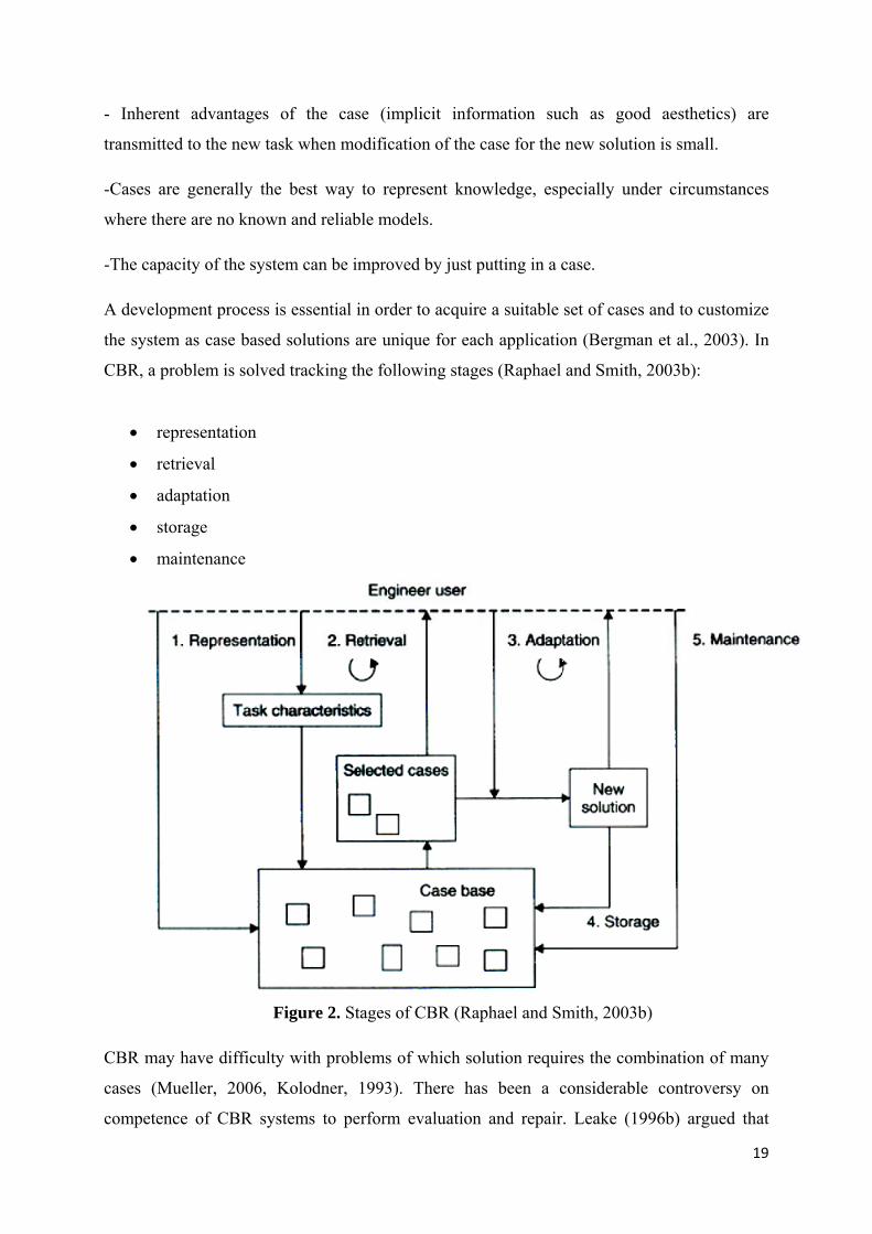
A development process is essential in order to acquire a suitable set of cases and to customize
the system as case based solutions are unique for each application (Bergman et al., 2003). In
CBR, a problem is solved tracking the following stages (Raphael and Smith, 2003b):
• representation
• retrieval
• adaptation
• storage
• maintenance
Figure 2. Stages of CBR (Raphael and Smith, 2003b)
CBR may have difficulty with problems of which solution requires the combination of many
cases (Mueller, 2006, Kolodner, 1993). There has been a considerable controversy on
competence of CBR systems to perform evaluation and repair. Leake (1996b) argued that

20
evaluation and repair steps are difficult challenges for CBR systems. On the other hand
Sycara (1988)and Kolodner (1993) stated that CBR can be used for evaluation and repair.
Smyth and Keane (1995) demonstrated that despite conventional deletion policies were
effective in controlling the swamping problem from a performance standpoint, they may
induce degradation of competence. A solution that uses a model of case competence to guide
the learning and deletion of cases is proposed.
The utility problem arises when the cost of search for relevant knowledge outweighs the
benefit of applying this knowledge. In CBR systems, the impact of utility problem is greatly
dependant on the size and growth of the case base. Larger case bases lead to more expensive
retrieval stages, an expensive overhead in CBR systems (Smyth and Keane, 1995).
Despite the fact that learning is crucial toward the ultimate aim of obtaining intelligent
structures, no study using the CBR approach in learning procedure of a civil engineering
structure could be found in the literature outside of work at EPFL.
2.8 System Identification
The aim of system identification is determining the state of a system along with key
parameters through comparisons of predictions with observed responses (Ljung, 1999).
System identification tasks are classified into identification of linear systems, identification of
nonlinear systems, online identification and real-time identification (Åström and Eykhoff,
1971). Statistical methods such as least squares, generalized least squares, correlated
residuals, and maximum likelihood methods are efficient for linear systems (Åström and
Eykhoff, 1971). Eykhoff (1974) researched into applications of system identification methods
in nuclear reactors, power distribution strategies and aerospace engineering. A unified
approach to nonlinear system identification was introduced by Billings and Fakhouri (1982).
Frank (1990) studied on fault detection and isolation in automatic processes, and presented a
robust fault detection method decoupling the effects of faults from each other and from the
effects of modeling errors. Richalet (1993) demonstrated the relationship between control
robustness and identification uncertainty. Bloch et al. (1995) presented a method that can
detect faults, their type and locations simultaneously. Gray et al. (1998) presented an
algorithm for identification of nonlinear systems and apply it to identification of the outlet

21
flow of a coupled water tank system identification of engine dynamics within the control of
the speed of a helicopter rotor. Morimoto and Hashimoto (2000) approached to identification
and control of plant production from an artificial intelligence point of view. They applied an
intelligent control technique consisting of two decision systems, an expert system, and an
optimizer based on neural networks and genetic algorithms (GA), to optimization of
hydroponic tomato cultivation and storage. Kowalczuk and Kozlowski (2000) presented a
continuous-time approach to identification of continuous-time systems. Ohsumi et al. (2002)
proposed a novel approach to system identification of continuous-time stochastic state space
models from random input-output continuous data. Akanyeti et al. (2008) used system
identification techniques that produce linear and non-linear polynomial functions that model
the relationship between a robot's sensor perception and motor response. Benfratello et al.
(2009) studied system identification from a civil engineering standpoint and formulated a time
domain dynamic identification technique based on a statistical moment approach for civil
structures under base random excitations in linear state. One of the recent developments in
system identification field is swarm intelligent domain. Ant colony optimization, particle
swarm optimization and stochastic diffusion search are the subclasses of swarm optimization.
Majhi and Panda (2009) introduced the problem and importance of adaptive nonlinear system
identification and proposes two new approaches based on swarm intelligence to identify
complex nonlinear dynamic plants. The proposed new approaches are fast, relatively accurate
and involve less computation.
Structural identification has been of much interest to the researchers from civil and structural
engineering fields, particularly in structural health monitoring context. Farrar and James
(1997) proposed an ambient vibration system identification method and experimentally
verified that the proposed method can be used accurately to assess the dynamic properties of
bridges and other structures in a non-intrusive manner. Shenton and Zhang (2001) developed
a method for system identification that is based on fitting the theoretical probability density
function for the time between zero crossings to a measured distribution of the crossing
interval times. This new methodology in conjunction with the peak meter, was concluded to
have potential to reduce time, labor and cost of conducting ambient vibration surveys of large
civil engineering structures. Catbas et al. (2008) presented reliability estimation studies for a
long span truss bridge. Brownjohn and Middleton (2008) studied vibration serviceability of
high-frequency floors from a system identification point of view. The conclusion was that
there were no shortcuts to predicting response of high-frequency floors to footfall excitation.

22
Gul and Catbas (2009) used statistical pattern recognition methodologies to detect changes in
different laboratory structures. Liu et al. (2009) proposed a competent approach to evaluating
the efficiency of retrofitting distortion-induced fatigue cracking in steel bridges by using both
analytical results from 3D finite element models and field monitored data from structural
health monitoring were used to estimate the fatigue reliability of the connection details after
retrofitting. Frangopol et al. (2008) presented a general approach for the development of
prediction functions and a procedure for the performance assessment of structures based on
monitored extreme data. Strauss et al. (2008) put forward a new approach for incorporate
monitoring data in structural reliability assessment based on performance prediction functions
using monitoring data. Kim and Frangopol (2009) proposed an approach for the determination
of optimal monitoring planning of structural systems based on reliability importance
assessment of structural components. Viguié and Kerschen (2009) studied the problem of
mitigating the vibration of nonlinear mechanical systems using nonlinear dynamical
absorbers. The proposed absorber was effective in a wide range of forcing amplitudes. A
qualitative tuning methodology was also developed and validated using numerical simulations
in this work. ASCE is currently preparing a comprehensive state-of-the-art report on structural
identification of constructed systems (Smith et al., 2009). Types of data interpretation, feature
selection, model identification and validation, model prediction and data mining, and benefits
of data interpretation aspects are covered in data interpretation section of this report. It is
concluded that many challenges, including application and adaptation of advanced computing
methods and stochastic search, remain in the field.
Although system identification is widely used in civil engineering practice, especially for
bridges, it has never been combined with reasoning and learning methods for a deployable
civil engineering structure.
2.9 Multi-Objective Search
An optimization task that has more than one objective is treated through multi-objective
optimization techniques. Resolving an optimization task require requires the generation of a
set of possible solutions, defined as those able to satisfy best and with different performances
objectives of the optimization task. These solutions are known as Pareto optimum or non-
dominated solutions. Pareto (1896) laid the foundations of multi-objective optimization by
introducing the Pareto optimum concept (1896, Wan, 1975). In a multi-objective
23
minimization task, a solution x* is said to be Pareto optimal if no feasible vector of decision
variables can be found that improves values for any objective function without causing a
simultaneous increase in other objectives. The solution is then selected between mutually non-
dominated candidates. However, in the absence of preference information, none of the Pareto
optimal solutions could be said to be better than the others.
Recent advances in multi-objective optimization resulted in reliable techniques for generating
non-dominated solutions. Evolutionary techniques are currently used in various fields due to
their effectiveness and robustness in searching for a set of trade-off solutions (Coello et al.,
2007). However, the selection of the “best solution” to be adopted among the Pareto optimum
set is a challenge. Several decision support systems have recently been proposed to help in the
selection of the best compromise alternatives. Major approaches to Multi-Criteria Decision
Making (MCDM) include multi-attribute utility theory and outranking methods (Coello,
2000). Incorporating preferences is also considered to help in handling conflicting objectives
(Fleming et al., 2005). Adam and Smith (2007) proposed and validated experimentally a
multi-objective approach to compute control commands for quasi-static control of tensegrity
structures. The search method is based on building a Pareto optimal solution set. A
hierarchical selection strategy is then adopted to reduce the solution space until identification
of a control command. Grierson (2008) proposed a MCDM strategy employing a tradeoff-
analysis technique to identify compromise designs for which the competing criteria are
mutually satisfied in a Pareto optimal set.
Mäkilä (1989) was the first to use Pareto approach to solve a control task. Khargonekar et al.
(1991) put forward that Pareto optimality is suitable to solve control tasks that involve trade-
offs between competing objectives. Lirov (1991) proposed a method to construct heuristics
that deals with search problems with multi-objective criteria that can be ranked in some
hierarchy. Ringuest and Gulledge (1992) presented an algorithm that provides an approach for
optimizing multiple objective problems subject to linear constraints. Jazskiewicz (2002)
proposed a GA for multi-objective combinatorial optimization. Cavin et al. (2004) presented a
new method for optimizing the implementation of a new single chemical process in a multi-
purpose batch plant using a flexible meta-heuristic algorithm. Brar et al. (2005) used fuzzy
logic for modeling the conflicting objectives of a thermal power generation scheduling
problem. Yan and Zhou (2006) presented a design method using fuzzy logic and GA for the

24
purpose of multi-objective control. Willis and Jones (2008) presented an optimization
framework to solve complex simulation models with multiple objectives.
While multi-objective search strategies have been implemented in a variety of fields, no
experimental studies of multi-objective structural control could be found in civil engineering
literature, aside from the study at EPFL.
3. RELEVANT RESEARCH AT IMAC, EPFL
3.1 Active Tensegrity Structures
Tensegrity has been one of the research fields studied at IMAC since 1996. Shea and Smith
(1998) put forward that the ultimate goal of intelligent structures is to maintain and improve
structural performance by recognizing changes in behaviors and loads, adapting the structure
to meet performance goals, and using past events to advance future performance. Shea et al.
(2002) imparted a computational procedure founded on intelligent control methodology that
combines reasoning with explicit knowledge, search, learning and planning to demonstrate the
concept of intelligent control applied on civil engineering structures. First, a full-scale
tensegrity structure was built (Fest, 2003). The structure comprises 5 modules, each module
consisting of 24 cables and 6 bars. It covers a total surface area of 15 m2 and has a static
height of 1.20 m. It can withstand a distributed dead load of 300 N2/m2. Cables are made of
stainless steel and bars are made of reinforced polymer. Bars meet in the center of a module
at the central node in order to enhance the buckling resistance of the bars. There has been a
considerable controversy between the first definitions of tensegrity and the more recent ones.
Tensegrity purists argue that members designed to carry compression forces must not contact
in a tensegrity structure in order that structure to be defined as tensegrity. On the other hand,
modern experts in the field use bar-bar connections in tensegrity designs (Djouadi et al.,
1998).

25
Figure 3. Elevation View of the First Tensegrity Structure at IMAC
The first tensegrity structure at IMAC is an active structure. Inductive displacement sensors
placed o the structure let the researchers have experimental data. In order to control the self-
stress state, ten active struts were used.
First, Fest presented a comprehensive description of the laboratory structure, as well as the
control system. Then, an algorithm to determine control commands that enable the structure to
satisfy the serviceability objective was established. The serviceability objective was to
maintain a constant slope of the top surface of the structure when the structure was subjected
to an additional load. The objective was to be achieved by contracting or elongating the active
struts. The process of finding the control commands was exponentially complex and required
generate-test procedures. A single-objective stochastic search algorithm (Raphael and Smith,
2003a) was chosen to perform the process (Domer, 2003, Fest et al., 2004)
3.2 Learning
Once the active tensegrity structure had been obtained, Domer and Smith (2005) studied on a
learning control system. Stochastic search and CBR was used. Successful control commands
were stored in a case-base and used afterward in similar situations in order to use previous
experience for new situations. A database system, Tensegrity Structure Analysis and Control
Software (TSACS) was established for the purpose of generating and administrating data

26
needed for analysis and control of the structure (Domer, 2003). The system architecture of
TSACS is demonstrated in Figure 3.
Figure 4. System Architecture of TSACS (DLL: dynamic link library) (Domer, 2003)
The core modules of the application and their functions are as follows:
Festorder: Generating geometry and topology data
Tensgraph: Visualizing the shape of the structure
Dynarex: Form-finding and structural calculation of structures stored
Optimiser: Searching for good control commands by using stochastic search
CBR: Improving the behavior of the system over time
While Fest used Simulated Annealing (SA) (Fest, 2003), results of Domer’s studies showed
that GA and Probabilistic Global Search Lausanne (PGSL) outperformed SA. PGSL with
cases was even 20 times faster than without cases. No maintenance problem occurred for the
studied structure. K-means clustering was used to avoid bottlenecks. Cases are clustered and
only the similarities of cases in the cluster close to the current case are calculated. Number of
clusters was determined such that retrieval time decreased significantly without affecting
system competence.

27
The computational framework developed by Domer comprises the following modules:
A central database to assure efficacy and accuracy of data used
General tools for the analysis of tensegrity structures: generating structures employing
IMAC’s module, displaying a 3-D model of the generated system and performing a
structural analysis.
A software module to search for good control commands that are governed by a
predefined objective function and constraints, search techniques implemented are SA,
PGSL and GA.
A module which models the CBR process to re-use good past control
commands and adapt them to the current situation. Performance is maintained by
clustering stored cases.
Although Domer achieved decreased computation time, he did not study control command
quality enhancement. Besides, it was assumed that both load positions and magnitudes were
known in Domer’s studies.
Subsequently, Adam described intelligent control methodologies such as self diagnosis, multi-
objective shape control, self-repair and reinforcement learning and validated them
experimentally. The learning procedure used by Adam is given in Figure 4. At this procedure,
when a loading event occurs, corresponding response of the structure is compared to the past
cases. If there is a similar case in the case base, it is retrieved and adapted. Then, control
commands are applied and the active members are actuated. If there is no past case that is
similar to the current case, self-diagnosis procedure is applied as multi-objective control
command. Then, the active members are actuated by using these control commands. The
adapted cases are used taking out the current case.

28
Figure 5. Learning process used by Adam (2007)
Adam (2007) stated that the proposed algorithm of reinforcement learning can be applied to
more complex structures in view of the fact that cases were classified and iteratively replaced
in the case base. Case-base management methodologies, such as clustering were not needed.
Moreover, case base size was expected to reach a saturation point where cases were retrieved
for each control event and no more cases were added in the case base. The control loop used
by Adam is shown in Figure 6.
Figure 6. Intelligent control methodologies used by Adam (2007)
Structure
Load
Self diagnosis
Multi-objective command
computation
Control command application
Reinforcement learning
Structure
Loading event
Self diagnosis
Multi-objective control command
search
Control command application
Reinforcement learning
29
The intelligent control methodology used by Adam is briefly demonstrated Figure 6. Once a
loading event occurs in the structure, self-diagnosis and multi-objective control command
search or directly reinforcement learning procedure decides the suitable control command.
Then, the structure undergoes alterations by having length changes in the active members.
3.3 Multi-Objective Control
Adam used multi-objective control to select control commands for shape control of the active
tensegrity structure described section 3.1. The control objectives were:
Slope: maintaining top surface slope of the structure,
Stress: minimizing stress ratio of the most stressed element,
Stroke: maintaining active strut jacks as close as possible to their midpoint,
Stiffness: maximizing the stiffness of the structure.
Multi-objective search was used in conjunction with Pareto approach in order to elude any
lack of precision related to weight coefficients (Adam, 2007). It was concluded that Pareto
filtering followed by a hierarchical selection strategy was preferable to compute control
commands that maintain robustness of both the structure and the active control system better
than single objective control, where multiple loading events were successively applied. Multi-
objective control is efficient when used together with self-diagnosis to control an active
tensegrity structure. Besides, it was demonstrated that controlling multiple characteristics of
an active tensegrity structure such as shape, stress and stiffness was feasible. However, Adam
started with a list of all possible cables that can be broken in the structure. This scheme would
be inefficient for bigger structures.
3.4 Self-Diagnosis and Self-Repair
Adam (2007) proposed a self-diagnosis methodology to identify loads that are applied to the
structure and locate damage. Active control was extended to adaptation in partially defined
environments by self diagnosis. Partially defined damage was a known type and unknown
location. Active control system was used to support self-diagnosis. It was concluded that
although load identification did not always identify exact loading situations, differences

30
between self-diagnosis results and experimental results were smaller than difference between
numerical simulation and real behavior. These results allowed for improvement of slope
compensation in comparison with introducing load magnitude and location manually. On the
other hand, when damage location was not exact, self-repair could lead to a stress increase.
Stresses varied between candidate solutions since no information on stresses was used for self
diagnosis.
Figure 7. Self-repair procedure used by Adam (2007)
In Figure 7, the self-repair procedure used by Adam is given. The sensors on the structure
gather the necessary data. Control computer processes the data and creates the movements to
be applied on actuators. Actuators apply the movements to the structure in order to diminish
the affect of the perturbation to which the structure is subjected.
Deficiencies in the literature establish the originality of the objectives of the proposed
research. The following conclusions are drawn:
Although computer scientists have used biomimetic approaches for programming
targets, the application of biomimetic computing approaches have rarely been
integrated in civil engineering structures.
The number of studies on tensegrity structures in the literature is a small percentage of
the total number of studies on structural systems. The absence of appropriate
analytical tools has hindered the tensegrity concept from taking its rightful place
among other structural engineering solutions.

31
Tensegrity structures have been numerically studied and they have been tested mainly
on small, simple and symmetric tensegrity models.
Deployable tensegrity structures have been studied only for the purpose of space
applications. No study of a deployable tensegrity civil engineering structure could be
found in the literature.
Most of the studies on active control of civil structures are carried out numerically
only.
System identification has never been combined with reasoning and learning methods
for a deployable civil engineering structure.
Aside from the study at EPFL, no experimental studies of multi-objective structural
control could be found in civil engineering literature.
Except for the study at EPFL, no experimental demonstration of self-repair of civil
engineering structures could be found in the literature.
Aside from the study at EPFL, learning methodologies have not been applied to
control system for civil engineering structures.
A number of studies have been carried out on passive control strategies for civil
engineering structures. On the other hand, no civil engineering structure that uses
active control strategies for shape control and self-repair purposes could be found in
the literature.
The objectives of this research have been formulated to fill these research voids through
building on and extending previous work at EPFL and elsewhere.
32
4. PRELIMINARY RESULTS
4.1. Need for Active Control In Terms of Damage Tolerance
The deployable tensegrity bridge described in Rhode-Barbarigos’ research proposal is based
on hollow rope concept (Motro et al., 2006). It has been analyzed for its potential to be
actively controlled with purpose of maintaining damage tolerance.
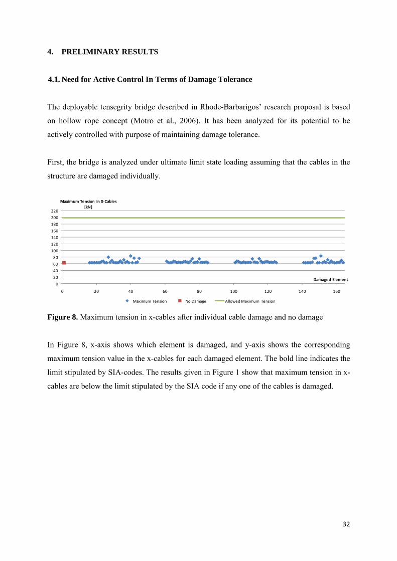
First, the bridge is analyzed under ultimate limit state loading assuming that the cables in the
structure are damaged individually.
Figure 8. Maximum tension in x-cables after individual cable damage and no damage
In Figure 8, x-axis shows which element is damaged, and y-axis shows the corresponding
maximum tension value in the x-cables for each damaged element. The bold line indicates the
limit stipulated by SIA-codes. The results given in Figure 1 show that maximum tension in x-
cables are below the limit stipulated by the SIA code if any one of the cables is damaged.
0
20
40
60
80
100
120
140
160
180
200
220
0 20 40 60 80 100 120 140 160
Maximum Tension in X‐Cables [kN]
Damaged Element
Maximum Tension No Damage Allowed Maximum Tension

33
Figure 9. Maximum tension in layer cables after individual cable damage and no damage
In Figure 9, x-axis shows which element is damaged, and y-axis shows the corresponding
maximum tension value in the layer cables for each damaged element. The bold line indicates
the limit stipulated by SIA-codes. If any cable is damaged, maximum tension in layer cables
are lower than SIA-code requirements.
Figure 10. Maximum compression in struts after individual cable damage and no damage
In Figure 10, x-axis shows which element is damaged, and y-axis shows the corresponding
maximum compression value in the x-cables for each damaged element. The bold line
indicates the limit stipulated by SIA-codes. Maximum compression criterion is governed by
the buckling strength of the struts. The results indicate that there would be no excessive
compression in any of the struts if any of the cables is damaged.
It has been demonstrated that the safety requirements of SIA-codes are met for this structure,
if any of the cables are damaged. Next, maximum displacements in the structure have been
investigated in the case of cable damage.
020406080
100120140160180200220
0 20 40 60 80 100 120 140 160
Maximum Tension in Layer Cables [kN]
Damaged ElementMaximum Tension No Damage Allowed Maximum Tension
020406080
100120140160180200220
0 20 40 60 80 100 120 140 160
Maximum Compression in Struts [kN]
Damaged Element
Maximum Compression No Damage Allowed Maximum Compression

34
Figure 11. Displacement at midspan node 17 after individual cable damage and no damage
Figure 12. Displacement at midspan node 18 after individual cable damage and no damage
In Figure 11 and Figure 12, x-axes show which element is damaged, and y-axes show the
corresponding displacement value at the two midspan nodes (Node 17 and Node 18) for each
damaged element. The bold line indicates the displacement limit calculated by using SIA-
codes. As can be seen from Figure 4 and Figure 5, displacements at midspan nodes, which are
the maximum displacements in the structure, are above the limit stipulated by SIA-codes.
That is to say, the structure cannot accommodate the affects of cable damage in terms of
serviceability. Therefore, this structure must be actively controlled in order to make sure that
the structure will be serviceable in cases of cable damage, which can be possible due to
events, such as vandalism and maintenance operations.
The structure is also analyzed in terms of twisting behavior. In Figure 13, x-axis shows the
cable that is damaged, and y-axis shows the twisting angle between two lateral midspan
nodes. The angle between two lateral midspan nodes at the individual cable damage scenarios
‐6
‐5.5
‐5
‐4.5
‐4
‐3.5
‐3
‐2.5
‐2
0 20 40 60 80 100 120 140 160
Displacement at Node 17 [cm]
Damaged ElementDisplacement No Damage Allowed Maximum Displacement
‐6
‐5.5
‐5
‐4.5
‐4
‐3.5
‐3
‐2.5
‐2
0 20 40 60 80 100 120 140 160
Displacement at Node 18 [cm]
Damaged ElementDisplacement No Damage Allowed Maximum Displacement

35
is found to be within a band of (-0.1°; 0.1°), except for the case of individual damages of
cable 80 and cable 111 (see Figure 12), which are directly connected to the midspan nodes.
Even if cable 80 or cable 111 goes slack, the twisting magnitude is below 0.5°.
Figure 13. Angle between the midspan nodes after individual cable damage and no damage
4.2 Formulation of Optimization Problem
The active control task is formulated as an optimization problem. It is mathematically
formulated as follows:
min f ∑ |∆Li|NAGn 1 (Eq. 1)
where ∆Li is the actuation length for active group i and NAG is the number of active groups.
The objective of this task is minimizing the total actuation length (Eq.1) along with the
following constraints defined by SIA-Codes:
Nxc ≤ Nxc,limit (Eq. 2)
Nlc ≤ Nlc,limit (Eq. 3)
Ns ≤ Ns,limit (Eq. 4)
δmidspan≤ δlimit (Eq. 5)
where:
Nxc: Maximum tension in x-cables
Nlc: Maximum tension in layer cables
Ns: Maximum compression in struts
‐0.5
‐0.4
‐0.3
‐0.2
‐0.1
0
0.1
0.2
0.3
0.4
0.5
0 20 40 60 80 100 120 140 160
Angle between Node 17 and Node 18 [°]
Damaged ElementAngle No Damage

36
δmidspan: Maximum displacement of the two midspan nodes (Node 17 and Node 18)
Due to the complexity of the problem, a stochastic search method is more suitable than a
deterministic method. The nature of the problem is combinatorial and includes a large number
of continuous variables. Also, the optimization constraints cannot be expressed explicitly with
the optimization variables. Therefore, PGSL (Raphael and Smith, 2003a, Raphael and Smith,
2000) is a convenient search method to be used.
4.3 Case Studies
Damage scenarios are chosen considering the displacements at the midspan nodes. The
greatest displacements that come into being in case of individual cable damage have been
determined (see Table 1), and the resulting cable damage is repaired by actuating the active
cables. When these cables are damaged, the maximum displacement magnitudes at the
midspan nodes are between 5.807 cm 3.504 cm. However, SIA code requirement for
displacement magnitude is a maximum value of 2.85 cm for the studied structure.
The consecutive cables, of which numbers are highlighted with the same shading in Table 1,
are symmetric along the middle pentagon layer of the structure.
Table 1. Greatest midspan displacements in case of individual cable damage in the structure
Results show that damage of the cables that are symmetric along the middle pentagon layer of
the structure result in the same displacement behavior at two different lateral midspan nodes.
The cables that makes the midspan nodes undergo the greatest displacements have been
chosen for the case studies with the assumption that it would be possible to bring back the
Damaged Cable No. Displacement at Node 17 [cm] Displacement at Node 18 [cm]42 ‐3.525 ‐3.026148 ‐3.026 ‐3.52576 ‐3.874 ‐3.793115 ‐3.793 ‐3.87479 ‐3.767 ‐3.208112 ‐3.208 ‐3.76780 ‐5.807 ‐2.189111 ‐2.189 ‐5.807106 ‐3.504 ‐3.03884 ‐3.038 ‐3.504

37
displacements that are caused by the damage of the remaining cables with an active control
system that is capable of repairing the structure even in the cases at which the cables that
makes the midspan nodes undergo the greatest displacements are damaged.
Figure 14. Most critical cables
0200
400600
8001000
12001400
16001800
2000
-500
0
500
-500
-400
-300
-200
-100
0
100
200
300
400
500
142152
141
149
153
136
137143127
148
156
150
126
145
147
151
138
140
133
157
164
144
128102
146
154
139132
134
160
165
112
101
130
161
109
113
155
162
129
96
97103
131
135
87
108
116
158
163
110
86
105
159
107
111
98
100
93
117
124
104
8862
106
114
99
X [cm]
92
94
120
125
72
61
90
121
69
73
115
122
89
56
5763
91
95
Isometric View of the Structure with Damaged Cables That Lead to the Greatest Midspan Displacements
47
68
76
118
123
70
46
65
119
67
71
58
60
53
77
84
64
4822
66
74
5952
54
80
85
32
21
50
81
29
33
75
82
49
11
1223
51
55
2
28
36
78
83
30
1
25
79
27
31
13
15
8
37
44
24
317
26
34
147
9
40
45
16
5
41
35
42
4
18
6
1038
4320
39
19
Y [cm]
Z [c
m]

38
The cable members of the structure are categorized into 4 groups as follows:
Group 1: Cables that are not coplanar with diagonal struts.
Group 2: X-cables that are not coplanar with diagonal struts and layer cables of the
first three pentagons.
Group 3: Cables that are coplanar with diagonal struts.
Group 4: X-cables that are coplanar with diagonal struts and layer cables of the last
three pentagons.
Figure 15. Active Cable Group 1 and Group 2
0 200 400 600 800 1000 1200 1400 1600 1800 2000
-500
0
500-500
-400
-300
-200
-100
0
100
200
300
400
500
142
141
152
143
149
153
136
137
145148
156
144
127138
140
157
164
126
139
150160
165
128
147
151
161
133
130146
154
132
134
129
102
155
162
101131
135112158
163
103
109
113
15996
97
105108
116
104
8798
100
117
124
86
99
110120
125
88
107
111
121
93
90106
114
92
94
89
62
115
122
6191
9572118
123
63
69
73
X [cm]
Isometric View of the Structure (Active member Group 1 and 2 Indicated in Bold)
11956
57
6568
76
64
4758
60
77
84
46
59
7080
85
48
67
71
81
53
5066
74
52
54
49
22
75
82
2151
553278
83
23
29
33
7911
12
2528
36
24
213
15
37
44
1
14
3040
45
3
27
31
41
8
526
34
7
9
4
17
35
42
166
1038
43
18
39
20
19
Y [cm]
Z [c
m]

39
Figure 16. Active Cable Group 3 and Group 4
For each cable that leads to greatest midspan displacements, 4 cases have been studied (see
Table 1).
The total actuation lengths needed to repair the structure in terms of cable damage are given
in Figure 17 and Figure 18. When only active cable group 1 or 2 is actuated, the total
actuation lengths are smaller than the situation at which only active cable group 3 or 4 is
actuated. This result shows that, in this case, the active members needed for the purpose of
damage tolerance are in good accordance with the active members needed for the purpose of
deployment (Group 1 and Group 2).
In Figure 17 and Figure 18 x-axes show cables that are damaged at each case. Y-axes show
the total actuation length of all the cables that are actuated at each case. (e.g. in the first case,
cables 39, 40, 75 and 76 are damaged at once. The structure is repaired by using the active
cable group 1. The sum of the magnitudes of actuation lengths in this case is slightly below 20
mm. In the second case, cables 39, 40, 75 and 76 are damaged together. The structure is now
repaired by actuating the active cable group 2. The sum of the magnitudes of actuation lengths
in this case is also slightly below 20 mm.)
0200
400600
8001000
12001400
16001800
2000
-500
0
500-500
-400
-300
-200
-100
0
100
200
300
400
500
142152
141
149
153
136
137
143
127
148
156
150
126
145
147
151
138
140
133
157
164
144
128
102
146
154
139
132
134
112160
165
101
130
109
113
161
155
162
129
96
97
103
131
135
87
108
116
110158
163
86
105
107
111
159
98
100
93
117
124
104
88
62
X [cm]
106
114
99
92
94
72120
125
61
90
69
73
121
115
122
89
56
57
63
91
95
47
Isometric View of the Structure (Active member Group 3 and 4 Indicated in Bold)
68
76
70118
123
46
65
67
71
119
58
60
53
77
84
64
48
22
66
74
59
52
54
3280
85
21
50
29
33
81
75
82
49
11
12
23
51
55
2
28
36
3078
83
1
25
27
31
79
13
15
8
37
44
24
3
17
26
34
14
7
9
40
45
16
5
41
35
42
4
18
6
1038
4320
39
19
Y [cm]
Z [c
m]

40
Figure 17. Actuation lengths needed to repair the structure after cable damage (active cable
Group 1 and Group 2)
Figure 18. Actuation lengths needed to repair the structure after cable damage (active cable
Group 3 and Group 4)
In this preliminary study, 32 damage cases are simulated by using dynamic relaxation method
in MATLAB. Self-repair possibilities of the active deployable tensegrity bridge by using
active cables are investigated. Results show that the structure is capable of applying self-
repair actions.
0
20
40
60
80
100
120
140
160
180
39, 40, 75 and 76
42, 45, 79 and 80
84 106 111, 112, 147 and 148
115, 116, 151 and 152
Total Actuation Length [mm]
Damaged Cable(s)
Group 1
Group 2
0
20
40
60
80
100
120
140
160
180
38, 41, 83 and 84
42 76 79 80 106, 109, 150 and 153
111 112 115 148
Total Actuation Length [mm]
Damaged Cable(s)
Group 3
Group 4

41
4.4 Conclusions of the Preliminary Study
4.4.1 Feasibility of Active Control
The tensegrity bridge is shown to be meeting the safety requirements of SIA-codes even any
of its cables is damaged. On the other hand, in case of damage in some of the cables, the
structure fails to satisfy serviceability conditions set by SIA-codes. Therefore this structure is
a good candidate to be actively controlled for the purpose of damage tolerance.
4.4.2 Damage Tolerance vs. Deployment
The active cable groups that are devoted to deployment (Group 1 and Group 2) while
designing the structure by Rhode-Barbarigos perform better than the other two groups (Group
3 and Group 4), in terms of their capability of maintaining serviceability in case of cable
damages. That is, Group 1 and Group 2 are better candidates to be active than Group 3 and
Group 4.
4.4.3 X-cables vs. Layer Cables
It can be deduced from the data shown in Figure 17 that if Group 1 or Group 2 is activated,
there is minor difference between the total actuation lengths. On the other hand, this is not
valid when only Group 3 or Group 4 is actuated (see Figure 18). Taking into consideration the
technical difficulties in actuating the layer cables and better performance of Group 1 and
Group 2 than that of Group 3 and Group 4, Group 1 is the best candidate set of elements to
be active.
4.4.4 Grouping of Cables
Grouping active cables has its strengths and weaknesses. If the active cables are grouped, the
damage in one cable leads to greater displacements since all cables in the same group go
slack. On the other hand, the disadvantages of embedded actuation such as added mass and
cost, increased control complexity and energy consumption mean that grouping of active
cables is preferable.

42
4.4.5 Influence of Symmetry
For the case studies, no significant trend is observed between the repair opportunities in
damage case scenarios at which cables that are symmetrical along the middle pentagon layer
of the structure are damaged.
4.4.6 Optimization of Actuator Locations
Some clusters have a very small influence during the repair process. Therefore, the number of
active members in the structure can be reduced. In order to determine the optimum locations
of the active members, further studies without using the members that have smaller absolute
mean values of average actuation lengths and greater non-actuated cases/considered cases
ratios are to be performed. A sensitivity analysis can serve as a preliminary study for the
optimization of actuator positions. The efficiencies of each group of cables in terms of their
influences on the midspan displacements are to be determined.
5. RESEARCH PLAN
5.1 Summary of Objectives
This research will be carried out in close cooperation with the Ph.D. research by Rhode-
Barbarigos, entitled “An Active Deployable Structure”. Rhode-Barbarigos will study the
deployment of a tensegrity bridge, design an active control system to ensure deployment of
the bridge, study the structure in service (after deployment), and construct a near full-scale
tensegrity bridge model. In conjunction with this research, the following objectives and tasks
are to be achieved:
The objectives of this research are stated below:
1. Design an active control system for the purpose of ensuring the damage tolerance of a
deployable tensegrity pedestrian bridge
2. Extend existing strategies for self-diagnosis of the deployable tensegrity bridge to
avoid ambiguous results
3. Extend existing strategies in order to achieve a robust self-repair scheme

43
4. Design and develop algorithms that allow the active control system to learn, using
CBR by extending previous methods
5. Verify the control system components with experiments on a near full-scale (1/3)
model
5.2 Task Description
The aim of this research plan is to extend previous research on active control of structures
conducted at IMAC (see Section 3), including self-diagnosis, self-repair and learning aspects.
Foreseen tasks are categorized as follows:
Phase A: Literature review
Phase B: Optimization and design of an active control system for the purpose of
ensuring damage tolerance.
Phase C: Establishment of procedures for system identification and self-diagnosis
Phase D: Establishment of procedures for self-repair
Phase E: Development of algorithms in order to provide a learning active control system
Phase F: Experimental verification
Phase G: Documentation
Phases and corresponding tasks are elaborated below:
Phase A: Literature review
A1 Literature survey
An extensive relevant literature review will be performed throughout the duration of this
research. This task will not only provide the necessary theoretical background but will
also ensure that this research benefits from other advances in biomimetics, active
control of structures, self-diagnosis, self-repair, adaptive structures, intelligent
structures, tensegrity structures and deployable structures.
Phase B: Optimization and design of active control system for damage tolerance
In context of another Ph.D. thesis, Rhode–Barbarigos will provide an active control system in
relation with deployment strategies and a control algorithm that provides the deployment of

44
the structure. The context of this thesis includes the optimization of an active control system
for the purpose of damage tolerance only. The active members will be defined such that
structural serviceability is maintained in situations of partially defined damage.
B1 Determination of most critical cables
Pilot study shows that some cable members of the deployable tensegrity bridge are more
critical than the others. The most critical cables in terms of serviceability and damage
tolerance will be determined. Damage at critical cables in the structure will be simulated
and structural response to each damage will be evaluated.
B2 Damage case studies
Some case studies have already been carried out in order to determine the mechanical
behavior of the bridge with damaged elements. Further case studies, at which the most
critical cables are damaged, will be carried out. The damage of different combinations
of most critical cables will be simulated in order to interpret structural response. The
actuation lengths needed for each cable to maintain the serviceability criteria, which are
defined by SIA-codes, at damaged states will be determined. Results of the case studies
will lead to the design of an optimum active control system ensuring damage tolerance.
B3 Optimization of the active control system
The most critical active members in terms of serviceability at damaged states will be
decided. The active members that are critical in terms of damage tolerance may be also
critical for the deployment process. Therefore, this task will be carried out in close
cooperation with Rhode-Barbarigos. Locations and activation characteristics of the
active elements needed for optimum control will be determined.
Phase C: Establishment of procedures for system identification and self-diagnosis
C1 Study of the existing self diagnosis strategies for the context of the deployable tensegrity
bridge
Self-diagnosis involves identifying load positions and magnitudes as well as damage
locations. Damage will be simulated by removing single or multiple cables. The results
of the pilot study will be compared with damage identification and learning procedure

45
proposed previously. The self-diagnosis techniques used by Adam (2007) will be
studied for application to the deployable tensegrity bridge.
C2 Improvement of the existing self-diagnosis method
The current self diagnosis method will be improved for better search performance.
Adam started with a list of all possible cables that can be broken in the structure (2007).
This scheme will be replaced with a more efficient one, which can be applicable to more
complex structures. Optimization of sensor positions will be carried out. A sensitivity
analysis will be made in order to obtain the sensor positions that lead to better diagnosis.
C3 Integration of system identification into self-diagnosis procedure
Self-diagnosis will be supported with system identification techniques so that the
system will not need additional measurement locations. The methodology will be
founded on evaluating measured and calculated responses with respect to behavior
indicators such those developed by Adam. In order to achieve the demanding
requirements of self-diagnosis task, stochastic search and CBR will be utilized.
Phase D: Establishment of procedures for self-repair
D1 Grouping of active members
The pilot study showed that active members can be grouped without affecting efficiency
of self-repair. Different groups of cables, which have different behaviors in the way
they affect the structure, are expected to provide a more efficient way of self-repair.
Different rates of influence of different actuation lengths in different groups will be
compared and the best combination will be applied on the structure.
46
D2 Evaluation of self-repair strategies for the context of the deployable tensegrity bridge
Self-repair procedures such as those presented in (Adam, 2007) will be evaluated for
application to the deployable tensegrity bridge. Control objectives and application of
multi-objective approach will be assessed for the deployable tensegrity bridge.
D3 Enhancement and adaptation of self-repair methods
Self-repair methodologies will be extended in order to increase performance. Multi-
objective search will be used to improve control command selection. In situations of
damage, self-repairing control commands will be computed using damage location
solutions, which will be computed by self-diagnosis techniques, as input. Instead of
considering a single serviceability objective for self-repair, a multi-objective control
strategy will be proposed. Enhancement of control command search through use of
additional objectives can lead to increase robustness of both the structure and the
control system.
D4 Integration of Pareto optimum concept into self-repair process
Pareto filtering will be utilized in order to avoid the use of arbitrary assigned weight
factors. A set of Pareto optimal solutions according to multiple objectives will be built.
The solution generation process will be carried out using ParetoPGSL (Raphael and
Smith, 2000, Raphael and Smith, 2003a) algorithm, which generates solutions that
minimize each objective on its own and then solutions that minimize the sum of all
objectives.
D5 Control command selection strategy
In previous work at IMAC, a hierarchical selection strategy was proposed to decide on
one single solution among Pareto optimal solutions. The selection strategy
hierarchically reduces the set of Pareto optimal solutions until a solution singles out.
Multi-criteria decision making (MCDM) techniques will be evaluated for a better
selection of candidate solutions.

47
Phase E: Development of algorithms in order to provide a learning active control system
E1 Evaluation of the current learning strategies and their application to the deployable
tensegrity bridge
The learning procedure proposed by Adam (2007) will be applied to the CBR process of
the active control system. Adam divided the learning algorithm into memorization,
retrieval, adaptation and replacement processes. The adaptation procedure adapts a past
case that is better than a current case, taking out the current case.
E2 Enhancement of the efficiency of the current learning method
The learning procedure will be extended. In the CBR system used by Adam, the adapted
cases are used taking out the current case. Adam’s replacement procedure will be
enhanced by applying more elaborate techniques to the CBR system. In order to model
a competent CBR system and exploit this model to guard against competence depletion,
the size of the case-base will be controlled in a manner that avoids accumulation of too
many cases. Cases will be categorized into four classes. Pivotal and auxiliary cases will
represent the extremes of the competence model. Intermediate categories, namely
spanning and support cases will correspond to cases of which deletion may or may not
reduce competence depending on what other cases remain in the case-base. By
performing this categorization, it will be possible to obtain a picture of the case-related
competence of the system. Smyth and Keane’s (1995) approach to the utility problem
will be adapted for use in this situation.
E3 Assessment of the efficiency of the system to be proposed
Since the deployable tensegrity bridge is a relatively large civil engineering structure,
the efficiency of previously used learning procedures will be studied. A compromise
between the swamping problem and competence degradation will be identified. In this
context, decreased time for control command computation and increased control quality
over retrieved cases will be regarded as the attributes of a more efficient system.

48
Phase F: Experimental verification
F1 Comparison of general tendencies between computational simulations and a 1/10 scale
model of the tensegrity bridge
A 1/10 scale model of the tensegrity bridge will be constructed by using nylon tendons
and timber bars. The joints will be simple steel hooks, which allow movement of the
nylon wires. The damage scenarios studied in the scope of task B1 will be applied on
this model, and damage will be simulated by manually taking out cables. The tendencies
will be compared to the outcomes of task B1.
F2 Tests regarding self-diagnosis method used
Once the near full scale (1/3) deployable tensegrity bridge is built, self-diagnosis
methodologies used will be tested experimentally on the structure. Selected cables will
be taken out of the structure in order to simulate damage. Therewith, computational
results will be compared to actual behavior of the structure.
F3 Tests regarding self-repair method used
Proposed self-repair methods will be tested experimentally. Selected cables will be
taken out of the structure. Self-repairing actions of the structure, which is equipped with
a reasoning system, will be examined.
F4. Tests regarding learning strategies used
Learning behavior of the active control algorithms will be examined during the
experiments related to self-diagnosis and self-repair. It will be investigated whether the
algorithms provide a robust and efficient control system by learning phenomenon.
Phase G: Documentation
G1 Annual progress report
An annual progress report that will demonstrate the advances toward the objectives of
the thesis will be presented.
G2 International peer-reviewed journal papers
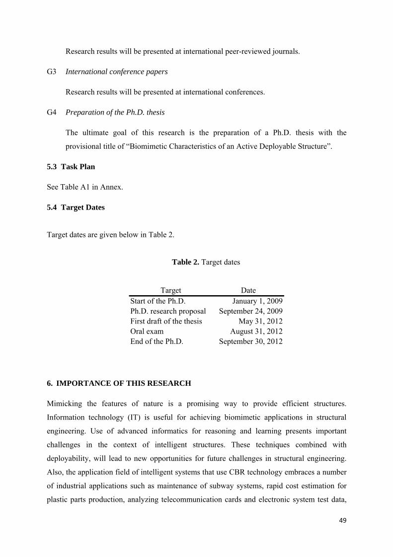
49
Research results will be presented at international peer-reviewed journals.
G3 International conference papers
Research results will be presented at international conferences.
G4 Preparation of the Ph.D. thesis
The ultimate goal of this research is the preparation of a Ph.D. thesis with the
provisional title of “Biomimetic Characteristics of an Active Deployable Structure”.
5.3 Task Plan
See Table A1 in Annex.
5.4 Target Dates
Target dates are given below in Table 2.
Table 2. Target dates
6. IMPORTANCE OF THIS RESEARCH
Mimicking the features of nature is a promising way to provide efficient structures.
Information technology (IT) is useful for achieving biomimetic applications in structural
engineering. Use of advanced informatics for reasoning and learning presents important
challenges in the context of intelligent structures. These techniques combined with
deployability, will lead to new opportunities for future challenges in structural engineering.
Also, the application field of intelligent systems that use CBR technology embraces a number
of industrial applications such as maintenance of subway systems, rapid cost estimation for
plastic parts production, analyzing telecommunication cards and electronic system test data,
Target DateStart of the Ph.D. January 1, 2009Ph.D. research proposal September 24, 2009First draft of the thesis May 31, 2012Oral exam August 31, 2012End of the Ph.D. September 30, 2012

50
failure analysis of semiconductors, intelligent product assistants, troubleshooting in airplane
engines, and heating, ventilating and air-conditioning (HVAC) systems. Applying advanced
informatics to a structural system, tensegrity, has potential to contribute innovatively to other
fields.
Although research into biomimetics is not new, application to active structures, deployable
structures and tensegrity structures presents unique challenges. This research will contribute
to demonstrating that biomimetic approaches can result in innovative structural engineering
solutions when combined with advanced computing methodologies.
7. TABLE OF CONTENTS OF THE THESIS
1. Introduction
1.1 Motivations
1.2 Objectives
1.3 Plan of the Thesis
2. State of the Art
2.1 Biomimetics
2.2 Structural Control
2.3 Tensegrity Structures
2.4 Deployable Structures
2.5 Deployable Tensegrity Structures
2.6 Active Tensegrity Structures
2.7 Case-Based Reasoning
2.8 System Identification
2.9 Multi-Objective Search
2.10 Relevant Previous Studies at IMAC
3. Structure Description
3.1 Deployable Tensegrity Bridge
3.2 Active Control System
4. Self Diagnosis
4.1 Load Identification
4.2 Damage Identification

51
4.3 Conclusions
5. Self-Repair
5.1 Multi-Objective Control
5.2 Repair Process
5.3 Conclusions
6. Learning
6.1 Learning Methodologies
6.2 Learning process
6.3 Conclusions
7. Conclusions and Future Work
7.1 Conclusions
7.2 Future Work
Chapters 4, 5 and 6 will be extended as results are obtained and as new ideas emerge.
8. FUNDING
Equipment that will be used during this research will be funded by the Swiss National Science
Foundation.
9. COLLABORATION
This thesis will be directed by Prof. I.F.C. Smith and supervised by Dr. Nizar Bel Hadj Ali at
IMAC, EPFL. The following experts will also be asked to provide additional advice:
Prof. René Motro, Montpellier University, France
Dr. Bernard Adam
Dr. Bernd Domer
Dr. Daniele-Claude Martin, Ulm University, Germany

52
10. REFERENCES
ADAM, B. 2007. Adaptive civil engineering structures. EPFL.
ADAM, B. & SMITH, I. F. C. 2006. Self-aware and learning structure. Intelligent computing
in engineering and architecture. Ascona, Switzerland: Springer.
ADAM, B. & SMITH, I. F. C. 2007. Tensegrity Active Control: Multiobjective Approach.
Journal of Computing in Civil Engineering, 21, 3-10.
ADAM, B. & SMITH, I. F. C. 2008. Reinforcement Learning for Structural Control. Journal
of Computing in Civil Engineering, ASCE, 22, 133-139.
AKANYETI, O., NEHMZOW, U. & BILLINGS, S. A. 2008. Robot training using system
identification. Robotics and Autonomous Systems, 56, 1027-1041.
ANDO, K., MITSUGI, J. & SENBOKUYA, Y. 2000. Analyses of cable-membrane structure
combined with deployable truss. Computers & Structures, 74, 21-39.
ANSHUMAN, S. & KUMAR, B. Year. Intelligent Building Façades: Beyond Climatic
Adaptivity. In: LUCIO, S. & FENIOSKY, P.-M., eds., 2005. ASCE, 99.
ARSENAULT, M. & GOSSELIN, C. M. 2006. Kinematic, static and dynamic analysis of a
planar 2-DOF tensegrity mechanism. Mechanism and Machine Theory, 41, 1072-
1089.
ÅSTRÖM, K. J. & EYKHOFF, P. 1971. System identification--A survey. Automatica, 7, 123-
162.
BENFRATELLO, S., CAVALERI, L. & PAPIA, M. 2009. Identification of stiffness,
dissipation and input parameters of multi degree of freedom civil systems under
unmeasured base excitations. Probabilistic Engineering Mechanics, 24, 190-198.
BERGMAN, R., ALTHOFF, K.-D., BREEN, S., GÖKER, M., MANAGO, M.,
TRAPHÖNER, R. & WESS, S. 2003. Developing Industrial Case-Based Reasoning
Applications.
BILLINGS, S. A. & FAKHOURI, S. Y. 1982. Identification of systems containing linear
dynamic and static nonlinear elements. Automatica, 18, 15-26.
BLOCH, G., OULADSINE, M. & THOMAS, P. 1995. On-line fault diagnosis of dynamic
systems via robust parameter estimation. Control Engineering Practice, 3, 1709-1717.
BRAR, Y. S., DHILLON, J. S. & KOTHARI, D. P. 2005. Fuzzy satisfying multi-objective
generation scheduling based on simplex weightage pattern search. International
Journal of Electrical Power & Energy Systems, 27, 518-527.
53
BROWNJOHN, J. M. W. & MIDDLETON, C. J. 2008. Procedures for vibration
serviceability assessment of high-frequency floors. Engineering Structures, 30, 1548-
1559.
CATBAS, F. N., SUSOY, M. & FRANGOPOL, D. M. 2008. Structural health monitoring
and reliability estimation: Long span truss bridge application with environmental
monitoring data. Engineering Structures, 30, 2347-2359.
CAVIN, L., FISCHER, U., GLOVER, F. & HUNGERBÜHLER, K. 2004. Multi-objective
process design in multi-purpose batch plants using a Tabu Search optimization
algorithm. Computers & Chemical Engineering, 28, 459-478.
CHEN, Y., YOU, Z. & TARNAI, T. 2005. Threefold-symmetric Bricard linkages for
deployable structures. International Journal of Solids and Structures, 42, 2287-2301.
COELLO, C., LAMONT, G. & VELDHUIZEN, D. V. 2007. Evolutionary Algorithms for
Solving Multi-Objective Problems, Springer US.
COELLO, C. A. C. Year. Handling preferences in evolutionary multiobjective optimization: a
survey. In: Evolutionary Computation, 2000. Proceedings of the 2000 Congress on,
2000. 30-37 vol.1.
DENNING, P. J. 1976. Fault Tolerant Operating Systems. ACM Computing Surveys 8, 359-
389.
DJOUADI, S., MOTRO, R., PONS, J. C. & CROSNIER, B. 1998. Active Control of
Tensegrity Systems. Journal of Aerospace Engineering, 11, 37-44.
DOMER, B. 2003. Performance enhancement of active structures during service lives. Ecole
polytechnique fédérale de lausanne.
DOMER, B. & SMITH, I. F. C. 2005. An Active Structure that Learns. Journal of Computing
in Civil Engineering, 19, 16-24.
ELSEAIDY, W. M., CLEAVELAND, R. & BAUGH, J. W. 1997. Modeling and verifying
active structural control systems. Science of Computer Programming, 29, 99-122.
EYKHOFF, P. 1974. System Identification Parameter and State Estimation, London, New
York, John Wiley & Sons.
FARRAR, C. R. & JAMES, G. H. 1997. SYSTEM IDENTIFICATION FROM AMBIENT
VIBRATION MEASUREMENTS ON A BRIDGE. Journal of Sound and Vibration,
205, 1-18.
FEST, E. 2003. Une structure active de type tensegrité.
FEST, E., SHEA, K. & SMITH, I. F. C. 2004. Active Tensegrity Structure. Journal of
Structural Engineering, 130, 1454-1465.

54
FLEMING, P. J., PURSHOUSE, R. C. & LYGOE, R. J. 2005. Many-Objective Optimization:
An Engineering Design Perspective. Evolutionary Multi-Criterion Optimization.
FLOREANO, D. & MONDADA, F. 1998. Evolutionary neurocontrollers for autonomous
mobile robots. Neural Networks, 11, 1461-1478.
FRANGOPOL, D. M., STRAUSS, A. & KIM, S. 2008. Use of monitoring extreme data for
the performance prediction of structures: General approach. Engineering Structures,
30, 3644-3653.
FRANK, P. L. M. 1990. Fault diagnosis in dynamic systems using analytical and knowledge-
based redundancy : A survey and some new results. Automatica, 26, 459-474.
FREELAND, R. E. 1983. Survey of deployable antenna concepts. In: ANISIMOVA, G. B.
(ed.) Satellite communication antenna technology. Amsterdam.
FULLER, R. B. 1959. Tensile integrity structures.
FULLER, R. B. & APPLEWHITE, E. J. 1975. Synergetics: Explorations in the Geometry of
Thinking, Scribner.
GANTES, C. J. 2001. Deployable Structures : Analysis and Design, WIT Press.
GANTES, C. J., CONNOR, J. J., LOGCHER, R. D. & ROSENFELD, Y. 1989. Structural
analysis and design of deployable structures. Computers & Structures, 32, 661-669.
GANTES, C. J. & KONITOPOULOU, E. 2004. Geometric design of arbitrarily curved bi-
stable deployable arches with discrete joint size. International Journal of Solids and
Structures, 41, 5517-5540.
GOUGH, M. 1998. In the Laboratory of Constructivism: Karl Ioganson's Cold Structures
JSTOR, 84, 90-117.
GRAY, G. J., MURRAY-SMITH, D. J., LI, Y., SHARMAN, K. C. & WEINBRENNER, T.
1998. Nonlinear model structure identification using genetic programming. Control
Engineering Practice, 6, 1341-1352.
GRIERSON, D. E. 2008. Pareto multi-criteria decision making. Advanced Engineering
Informatics, 22, 371-384.
GRUBER, P., HÄUPLIK, S., IMHOF, B., ÖZDEMIR, K., WACLAVICEK, R. & PERINO,
M. A. 2007. Deployable structures for a human lunar base. Acta Astronautica, 61,
484-495.
GUEST, S. D. & PELLEGRINO, S. 1996. A new concept for solid surface deployable
antennas. Acta Astronautica, 38, 103-113.
55
GUL, M. & NECATI CATBAS, F. 2009. Statistical pattern recognition for Structural Health
Monitoring using time series modeling: Theory and experimental verifications.
Mechanical Systems and Signal Processing, 23, 2192-2204.
HACHKOWSKI, M. R. & PETERSON, L. D. 1995. A comparative study of the precision of
deployable spacecraft structures. CU-CAS-95-22. Boulder, CO, USA: Center for
Aerospace Structures, University of Colorado.
HOUSNER, G. W., BERGMAN, L. A. & CAUGHEY, B. 1997. Structural Control: Past,
Present, and Future. Journal of Engineering Mechanics 123, 897-971.
INGBER, D. E. 1998. The Architecture of Life. Scientific American Magazine.
JASZKIEWICZ, A. 2002. Genetic local search for multi-objective combinatorial
optimization. European Journal of Operational Research, 137, 50-71.
JENSEN, F. & PELLEGRINO, S. 2001. Arm development-review of existing technologies.
CUED/D-STRUCT/TR198. Cambridge: University of Cambridge.
KANCHANASARATOOL, N. & WILLIAMSON, D. 2002. Modelling and control of class
NSP tensegrity structures. International Journal of Control, 75, 123-139.
KHARGONEKAR, P. P. & ROTEA, M. A. 1991. Multiple objective optimal control of linear
systems : the quadratic norm case. IEEE transactions on automatic control, 36, 14-24.
KIM, S. & FRANGOPOL, D. M. 2009. Optimal planning of structural performance
monitoring based on reliability importance assessment. Probabilistic Engineering
Mechanics, In Press, Corrected Proof.
KIPER, G., SÖYLEMEZ, E. & KISISEL, A. U. Ö. 2008. A family of deployable polygons
and polyhedra. Mechanism and Machine Theory, 43, 627-640.
KOLODNER, J. 1993. Case-based reasoning, Morgan Kaufmann.
KOWALCZUK, Z. & KOZLOWSKI, J. 2000. Continuous-time approaches to identification
of continuous-time systems. Automatica, 36, 1229-1236.
KOWALTOWSKI, D., LABAKI, L. C., DE PAIVA, V. T., BIANCHI, G. & MÖSCH, M. E.
2007. The creative design process supported by the restrictions imposed by
bioclimatic and school architecture: a teaching experience. 2nd PALENC Conference
and 28th AIVC Conference on Building Low Energy Cooling and Advanced
Ventilation Technologies in the 21st Century. Crete island, Greece
KUC, R. 1993. Three-dimensional tracking using qualitative bionic sonar. Robotics and
Autonomous Systems, 11, 213-219.
KURIBAYASHI, K., TSUCHIYA, K., YOU, Z., TOMUS, D., UMEMOTO, M., ITO, T. &
SASAKI, M. 2006. Self-deployable origami stent grafts as a biomedical application of
56
Ni-rich TiNi shape memory alloy foil. Materials Science and Engineering: A, 419,
131-137.
LALVANI, H. 1996. Origins of Tensegrity: Views of Emmerich, Fuller and Snelson.
International Journal of Space Structures, 11, 27-55.
LE SAUX, C., BOUDERBALA, M., CEVAER, F. & MOTRO, R. 1999. Strut-Strut contact
in numerical modeling of tensegrity system folding. 40th Anniversary of IASS, from
recent past to next millenium. Madrid, Spain.
LEAKE, D. B. 1996a. Case-Based Reasoning: Experiences, Lessons, and Future Directions
AAAI Press.
LEAKE, D. B. 1996b. CBR in Context: The Present and Future. Reasoning From
Remindings, 3-30.
LEAKE, D. B. & WILSON, D. C. 1999. When Experience is Wrong: Examining CBR for
Changing Tasks and Environments, Berlin/Heidelberg, Springer.
LI, T. & WANG, Y. 2009a. Deployment dynamic analysis of deployable antennas
considering thermal effect. Aerospace Science and Technology, 13, 210-215.
LI, T. & WANG, Y. 2009b. Performance relationships between ground model and space
prototype of deployable space antennas. Acta Astronautica, In Press, Corrected Proof.
LIROV, Y. 1991. Algorithmic multi-objective heuristics construction in the A * search.
Decision Support Systems, 7, 159-167.
LIU, M., FRANGOPOL, D. M. & KWON, K. 2009. Fatigue reliability assessment of
retrofitted steel bridges integrating monitored data. Structural Safety, In Press,
Corrected Proof.
LJUNG, L. 1999. System Identification: Theory for the User Prentice Hall PTR.
MAJHI, B. & PANDA, G. 2009. Development of efficient identification scheme for nonlinear
dynamic systems using swarm intelligence techniques. Expert Systems with
Applications, In Press, Corrected Proof.
MAKILA, P. M. 1989. On multiple criteria stationary linear quadratic control. IEEE
transactions on automatic control, 34, 1311-1313.
MANGE, D., MADON, D., STAUFFER, A. & TEMPESTI, G. 1997. Von Neumann
revisited: A turing machine with self-repair and self-reproduction properties. Robotics
and Autonomous Systems, 22, 35-58.
MANGE, D., SIPPER, M. & MARCHAL, P. 1999. Embryonic electronics. Biosystems, 51,
145-152.

57
MIKULAS, M. M., THOMSON, M. 1994. State of the arrt and technology needs for large
space structures, vol. 1: New and Projected Aeronautical and Space Systems, Design
Concepts , and Loads of Flight-Vehicle Materials, Structures, and Dynamics-
Assessment and Future Directions. New York: ASME.
MORIMOTO, T. & HASHIMOTO, Y. 2000. AI approaches to identification and control of
total plant production systems. Control Engineering Practice, 8, 555-567.
MOTRO, R. 2003. Tensegrity: Structural Systems for the Future, London, Sterling, Kogan
Page Science.
MOTRO, R., MAURIN, B. & SILVESTRI, C. 2006. Tensegrity Rings and the Hollow Rope.
IASS Symposium. New Olympics.
MUELLER, E. T. 2006. Commonsense Reasoning, Morgan Kaufmann.
NAWROTZKI, P. 2001. Passive control for buildings in seismically active regions. European
Conference on Computational Mechanics. Cracow, Poland.
OHSUMI, A., KAMEYAMA, K. & YAMAGUCHI, K.-I. 2002. Subspace identification for
continuous-time stochastic systems via distribution-based approach. Automatica, 38,
63-79.
PARETO, V. 1896. Cours d'Economie Politique, Lausanne, Switzerland.
PEDRETTI, M. 1998. Smart Tensegrity Structures for the Swiss Expo. Smart Structures and
Materials, 3330.
PELLEGRINO, S. 1995. Large retractable appendages in spacecraft. Journal of Spacecraft
and Rockets, 32, 1006-1014.
PUGH, A. 1976. An Introduction to Tensegrity University of California Pr.
RAMACHANDRA RAO, P. 2003. Biomimetics. Sadhana, 28, 657-676.
RAPHAEL, B. & SMITH, I. F. C. 2000. A probabilistic search algorithm for finding
optimally directed solutions.
RAPHAEL, B. & SMITH, I. F. C. 2003a. A direct stochastic algorithm for global search.
Applied Mathematics and Computation, 146, 729-758.
RAPHAEL, B. & SMITH, I. F. C. 2003b. Fundamentals of Computer Aided Engineering,
John Wiley & Sons Ltd.
RICHALET, J. 1993. Industrial applications of model based predictive control. Automatica,
29, 1251-1274.
RINGUEST, J. L. & GULLEDGE, T. R. 1992. An interactive multi-objective gradient search.
Operations Research Letters, 12, 53-58.

58
ROEDERER, A. G. R.-S., Y. 1989. Unfurlable satellite antennas: a review. Annales des
télécommunications, 44, 475-488.
ROGERS, C. A., STUTZMAN, W. L., CAMPBELL, T. G. & HEDGEPETH, J. M. 1993.
Technology Assessment and Development of Large Deployable Antennas. Journal of
Aerospace Engineering, 6, 34-54.
SCHNEIDER, A., FRASSON, L., PARITTOTOKKAPORN, T., RODRIGUEZ Y BAENA,
F. M., DAVIES, B. L. & HUQ, S. E. 2009. Biomimetic microtexturing for
neurosurgical probe surfaces to influence tribological characteristics during tissue
penetration. Microelectronic Engineering, 86, 1515-1517.
SHEA, K., FEST, E. & SMITH, I. F. C. 2002. Developing intelligent tensegrity structures
with stochastic search. Advanced Engineering Informatics, 16, 21-40.
SHEA, K. & SMITH, I. F. C. 1998. Intelligent structures: A new direction in structural
control. Artificial Intelligence in Structural Engineering. Ascona, Switzerland:
Springer
SHENTON, H. W. & ZHANG, L. 2001. SYSTEM IDENTIFICATION BASED ON THE
DISTRIBUTION OF TIME BETWEEN ZERO CROSSINGS. Journal of Sound and
Vibration, 243, 577-589.
SIPPER, M., MANGE, D. & STAUFFER, A. 1997. Ontogenetic hardware. Biosystems, 44,
193-207.
SKELTON, R. E. & DE OLIVEIRA, M. C. 2009. Tensegrity Systems, New York, Springer.
SKELTON, R. E., HELTON, J. W., ADHIKARI, R., PINAUD, J. P. & CHAN, W. 2000. An
Introduction to the mechanics of tensegrity structures. The Mechanical Systems Design
Handbook.
SMAILI, A. & MOTRO, R. 2007. Foldable/unfoldable curved tensegrity systems bby finite
mechanism activation. Journal of the International Association for Shell and Spatial
Structures, 48, 153-160.
SMITH, I. F. C., YUN, A., LU, Y., POSENATO, D., PEI, J., BELL, E. S. & KRIPAKARAN,
P. 2009. Structural identification of constructed systems ASCE.
SMYTH, B. & KEANE, M. T. 1995. Remembering to Forget: A Competence-Preserving
Case Deletion Policy for Case-Based Reasoning Systems. Fourteenth International
Joint Conference on Artificial Intelligence. Morgan Kaufmann.
SNELSON, K. 1965. Continuous tension, discontinuous compression structures. USA patent
application.
59
SOONG, T. T. & MANOLIS, G. D. 1987. Active Structures. Journal of Structural
Engineering, 113, 2290-2302.
SOYKASAP, Ö. 2009. Deployment analysis of a self-deployable composite boom. Composite
Structures, 89, 374-381.
STERRIT, R., PARASHAR, M., TIANFIELD, H. & UNLAND, R. 2005. A concise
introduction to autonomic computing. Advanced Engineering Informatics In
Autonomic Computing, 19, 181-187.
STRAUSS, A., FRANGOPOL, D. M. & KIM, S. 2008. Use of monitoring extreme data for
the performance prediction of structures: Bayesian updating. Engineering Structures,
30, 3654-3666.
SULTAN, C. 1999. Modeling, design, and control of tensegrity structures with applications.
Purdue University.
SULTAN, C. & SKELTON, R. E. 2003. Deployment of tensegrity structures. International
Journal of Solids and Structures, 40, 4637-4657.
SYCARA, K. Year. Patching Up Old Plans. In: Tenth Annual Conference of the Cognitive
Science Society, 1988.
TAKANO, T., NATORI, M., MIYOSHI, K. & INOUE, T. 2002. Characteristics verification
of a deployable onboard antenna of 10 m maximum diameter. Acta Astronautica, 51,
771-778.
TAN, G. E. B. & PELLEGRINO, S. 2008. Nonlinear vibration of cable-stiffened
pantographic deployable structures. Journal of Sound and Vibration, 314, 783-802.
TERMONIA, Y. 1994. Molecular modeling of spider silk elasticity. Macromolecules, 27,
7378-7381.
TEUSCHER, C., MANGE, D., STAUFFER, A. & TEMPESTI, G. 2001. Bio-Inspired
Computing Tissues: Towards Machines that Evolve, Grow, and Learn. Grow, and
Learn, BioSystems, 68, 235-244.
TIBERT, A. G. & PELLEGRINO, S. 2003. Review of Form-Finding Methods for Tensegrity
Structures. International Journal of Space Structures, 18, 209-223.
TIBERT, G. 2002. Deployable tensegrity structures for space applications. Royal Institute of
Technology.
UITZ, B. 1922. Egység. Berlin.
VAN DE WIJDEVEN, J. J. M. & DE JAGER, A. G. 2005. Shape change of tensegrity
structures: design and control. American Control Conference. Portland.

60
VASSART, N., LAPORTE, R. & MOTRO, R. 2000. Determination of mechanism's order for
kinematically and statically indetermined systems. International Journal of Solids and
Structures, 37, 3807-3839.
VIGUIÉ, R. & KERSCHEN, G. 2009. Nonlinear vibration absorber coupled to a nonlinear
primary system: A tuning methodology. Journal of Sound and Vibration, 326, 780-
793.
VON NEUMANN, J. 1966. Theory of Self-Reproducing Automata, Champaign, IL, USA
University of Illinois Press
WAN, Y.-H. 1975. On local Pareto optima. Journal of Mathematical Economics, 2, 35-42.
WILLIS, K. O. & JONES, D. F. 2008. Multi-objective simulation optimization through
search heuristics and relational database analysis. Decision Support Systems, 46, 277-
286.
XUN, J. & YAN, S. 2008. A revised Hilbert-Huang transformation based on the neural
networks and its application in vibration signal analysis of a deployable structure.
Mechanical Systems and Signal Processing, 22, 1705-1723.
YAN, G. & ZHOU, L. L. 2006. Integrated fuzzy logic and genetic algorithms for multi-
objective control of structures using MR dampers. Journal of Sound and Vibration,
296, 368-382.
YAO, J. T. P. 1972. Concept of structural control. ASCE Journal of the Structural Control,
98, 1567-1574.
ZHAO, J.-S., CHU, F. & FENG, Z.-J. 2009. The mechanism theory and application of
deployable structures based on SLE. Mechanism and Machine Theory, 44, 324-335.
ZHOU, H., SUN, N., SHAN, H., MA, D., TONG, X. & REN, L. 2007. Bio-inspired wearable
characteristic surface: Wear behavior of cast iron with biomimetic units processed by
laser. Applied Surface Science, 253, 9513-9520.