biomass-derived hydrogen from a thermally ballasted gasifier · biomass-derived hydrogen from a...
TRANSCRIPT

Biomass-Derived Hydrogen from a Thermally Ballasted Gasifier
Robert C. Brown, Glenn Norton, Andy Suby, Jerod Smeenk, Keith Cummer, and Josh Nunez Center for Sustainable Environmental Technologies
Iowa State University Ames, IA 50011-3020
INTRODUCTION
The goal of this project is to optimize performance of an indirectly heated gasification system that converts switchgrass into hydrogen-rich gas suitable for powering fuel cells. We have developed a thermally ballasted gasifier that uses a single reactor for both combustion and pyrolysis. Instead of spatially separating these processes, they are temporally isolated. The producer gas is neither diluted with nitrogen or the products of combustion. The heat released during combustion at 850°C is stored as latent heat in the form of molten salt sealed in tubes immersed in the fluidized bed. During the pyrolysis phase, which occurs at temperatures between 600 and 850°C, the reactor is fluidized with steam or recycled producer gas rather than air. Heat stored in the phase change material is released during this phase of the cycle to support the endothermic reactions of the pyrolysis stage. Because air is not used during the gas-producing phase of the cycle, nitrogen does not dilute the product gas, resulting in relatively high concentrations of hydrogen and carbon monoxide in the producer gas compared to conventional gasifiers. The carbon monoxide, along with steam used to fluidize the reactor, can be shifted to additional hydrogen by the water-gas shift reaction. Objectives in the first year include:
• Determine whether switchgrass is a suitable fuel for the ballasted gasifier. • Obtain time-resolved concentrations of important fuel components evolved. • Identify process conditions that maximize the production of hydrogen. • Evaluate methods for removing contaminants from the producer gas. • Evaluate methods for mediating the water-gas shift reaction in the product gas. • Estimate the economics of hydrogen production from switchgrass. The approach to this project employs a pilot-scale (5 ton per day) gasifier to evaluate the thermally ballasted gasifier as a means for producing hydrogen from switchgrass. Gasification at the pilot scale is important for obtaining realistic process data, especially for calculating energy flows through the system and assessing the practicality of feeding switchgrass into the gasifier. A series of gasification trials are being performed to evaluate the effect of biomass feed rate (fixed steam rate) and the effect of biomass/steam rate (fixed biomass feed rate) on hydrogen production. A slipstream from the gasifier is used to evaluate gas cleaning and upgrading options during the first year of research. This slip stream will include: a guard bed designed to remove hydrogen sulfide and hydrogen chloride and some tar; a steam reformer designed to crack the remaining tar and decompose ammonia; and high temperature and low temperature catalytic water-gas shift reactors to remove carbon monoxide from the product gas and increase its hydrogen content. A series of gasification trials will be performed to evaluate the effectiveness of these
1
Proceedings of the 2002 U.S. DOE Hydrogen Program Review NREL/CP-610-32405

four reactors in removing tar and contaminants, and shifting producer gas towards increased hydrogen and decreased carbon monoxide. Progress to date includes: modification of the gasifier to operate as a ballasted gasifier; assembly of a gas sampling system and a slipstream of the gasifier effluent; design and construction of a gas conditioning system; and identification of appropriate analytical methods for measurement of trace contaminants. Progress in each of these areas is detailed in the following sections.
RESULTS AND DISCUSSION
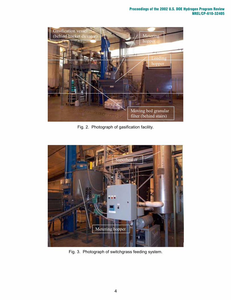
Modification of the Gasifier The 5 ton per day bubbling fluidized bed gasifier (gasifier) used in the project is located at the Biomass Energy Conversion (BECON) Facility, a facility dedicated to demonstrating biomass energy conversion technologies near Nevada, Iowa. Figure 1 is a schematic of the gasifier system. The gasifier was previously operated in a conventional, air-blown manner to produce low Btu-value gas (150-200 Btu/scf). The gasifier has been modified to operate as a ballasted gasifier. This entailed installation of the ballast system within the fluid bed reactor. The ballast system consists of 25.4 mm diameter stainless steel tubes that are 610 mm in length. Each of the ballast tubes is filled with 0.3 kg (0.66 lb) of LiF. An air pocket was left in each of the tubes to allow for expansion of the LiF. Forty-eight ballast tubes cover about 15% of the bed cross sectional area. This represents a total latent heat storage capacity of 15,100 kJ. The reactor will operate in a cyclic manner, switching between a combustion mode and a pyrolysis mode. A blower supplies air for fluidization and the oxygen supply during the combustion mode, while steam is used for fluidization during the pyrolysis mode. A steam generator, not originally present, has been installed with the financial assistance of the Iowa Energy Center. The saturated steam from the steam generator is piped to an electric heater that superheats the steam to 525°C. Several other modifications have been made to the gasifier system. An additional fuel hopper was added to the system to enable the use of multiple fuels. Both fuel hoppers were outfitted with load cells to accurately measure fuel flow into the gasification reactor. The moving bed granular filter, which will be evaluated for hot gas cleanup of particulate material in the producer gas, has been improved by the addition of a new auger system to remove dirty filter media from the bottom of the filter. The exhaust system, which was in poor repair, was replaced and upgraded to minimize the impacts of temperature on the system. Additionally, an automated high-temperature valve was installed to enable division of the pyrolytic gases from the combustion gases. Figure 2 is a photograph of the overall gasification system. It shows the loading hopper for chopped switchgrass, the bucket elevator that transports switchgrass to a metering hopper, as well as the location of the gasification vessel and moving bed filter, which are hidden by other structures in the photograph. Figure 3 is a close-up photograph of the metering hopper and the steam superheater to be used in the test program. Figure 4 is a photograph taken while the ballast assembly was being loaded into the gasification vessel. Figure 5 shows the ballast tubes in the gasification vessel, shown from above.
2
Proceedings of the 2002 U.S. DOE Hydrogen Program Review NREL/CP-610-32405

Fig. 1. Schematic of the gasifier system.
3
Proceedings of the 2002 U.S. DOE Hydrogen Program Review NREL/CP-610-32405
Metering hopper
Loading hopper
Gasification vessel (behind bucket elevator)
Moving bed granular filter (behind stairs)
Superheater
Metering hopper
Fig. 2. Photograph of gasification facility.
Fig. 3. Photograph of switchgrass feeding system.
4
Proceedings of the 2002 U.S. DOE Hydrogen Program Review NREL/CP-610-32405

Gasification vessel
Ballast tubes
Ballast assembly
Gasification vessel wall
Ballast support
Fig. 5. Photograph of ballast inside gasification vessel.
Fig. 4. Ballast tubes being lowered into gasification vessel.
5
Proceedings of the 2002 U.S. DOE Hydrogen Program Review NREL/CP-610-32405

Gas Sampling System and Slipstream for Gasifier Effluent Figure 6 is a flow diagram of the gas sampling system and the slipstream used on the producer gas effluent. Producer gas is extracted at two locations in the producer gas effluent. The first sampling point is positioned just downstream of the gasifier to provide raw gas characterization. This sampling is performed isokinetically to obtain a representative particulate loading. The isokinetically-sampled gas passes through a Mott Hyline porous metal filter operated at 450°C to prevent condensation of tar. The filter is located in an electrically heated oven for this purpose. The filter is operated in an “inside-out” configuration, which facilitates recovery of particulate for analytical purposes and eases filter cleaning. The gas then passes through a series of impingers containing varying combinations of dichloromethane (DCM) and glass beads. The impingers remove all condensable species, including tars and water. The Varian Micro-GC draws a small portion of the sample stream in order to characterize the gas, specifically for hydrogen (H2), carbon monoxide (CO), carbon dioxide (CO2), nitrogen (N2), methane (CH4) and ethylene (C2H4). The remaining portion of the sample stream is passed through a total volumetric gas meter and exhausted to atmosphere. The second extraction point is for the purpose of producing a slipstream of the gasifier effluent, which is used to evaluate an experimental gas conditioning system. A heated filter, similar to the one previously described, removes particulate matter, but gas is not sampled isokinetically as is done in the first gas extraction location. This is shown schematically in Figure 7. A high-pressure nitrogen back pulse can be used to restore the filter on a periodic basis. After passing through the gas conditioning system, described in the next section, the producer gas passes through on-line gas analyzers that monitor carbon monoxide (CO), carbon dioxide (CO2), oxygen (O2) and hydrogen (H2). The slipstream also provides a particulate-free gas for the quantification of trace contaminants such as hydrogen sulfide (H2S), hydrochloric acid (HCl), hydrogen cyanide (HCN) and ammonia (NH3). Trace contaminant measurement is described in a subsequent section. Construction and Installation of Gas Conditioning System Based upon previous work on the catalytic conversion of tars, new reactors have been designed and constructed. Improvements include the addition of standard flanges for better leakage control, upgraded reactor materials for improved characteristics in high-temperature environments, and welded joints in all areas inside the heated enclosures to vastly reduce leakage potential. Two more reactors were added for high-temperature and low-temperature hydrogen shift reaction purposes. Figure 8 shows the current design for the gas conditioning system. The reactor bodies are made of 1-1/4-inch pipes constructed with Haynes 230 and pre-manufactured flanges made of 304 stainless steel. The 3/8-inch inlet and outlet pipes are constructed with Haynes 230 material and have 3/8-inch stainless steel tube adapters welded to them. Each reactor has a volume of approximately 8.7 cubic inches (143 cubic centimeters). See Figure 9 for more details. The reactors are maintained at their specified temperatures by PID loop controllers connected to heating coils wrapped around the exterior of the reactors. The controllers are able to ramp to the specified set point at temperature increase rates defined by the user to reduce thermal shock on the reactors.
6
Proceedings of the 2002 U.S. DOE Hydrogen Program Review NREL/CP-610-32405

Total Flow Meter
Bubbling Fluidized
Bed Gasifier
Exhaust Gas
Diaphragm Pump Impinger Train
Impingers 1-4 immersed in ice bath. Impingers 5-6 submerged in acetone/dry ice bath.
Micro GCHeated Particulate
Filter
Flowrate:1.0 L/min
Diaphragm Pump
Exhaust Gas Dichloromethane
Mini-impinger TrainsFlowrate:
4.5-5.5 L/min CatalyticGuard Bed
CatalyticTar
Cracker
HT Water-
Gas Shift
LT Water-Gas Shift
Diaphragm Pump Heated
Particulate Filter
Sampling Port
Sampling Port
Sampling Port
Methanol Impinger Train Filter
Media
Trace Contaminant
Sampling System
Total Flow Meter
Exhaust Flow Switch
CO, CO2, O2 Analyzer
Required Flowrate:2 L/min
Moving Bed
Granular Detail of Trace Contaminant System shown on another page
Gas Bag Sampling Port
H2 AnalyzerRequired Flowrate:
1 L/minExhaust
Fig. 6. Overall schematic of gas sampling and slipstream from gasifier effluent.
7
Proceedings of the 2002 U.S. DOE Hydrogen Program Review NREL/CP-610-32405

Fig. 7. Cross-sectional view of non-isokinetic heated particulate filter.
8
Proceedings of the 2002 U.S. DOE Hydrogen Program Review NREL/CP-610-32405

Fig. 8. Gas conditioning system.
9
Proceedings of the 2002 U.S. DOE Hydrogen Program Review NREL/CP-610-32405
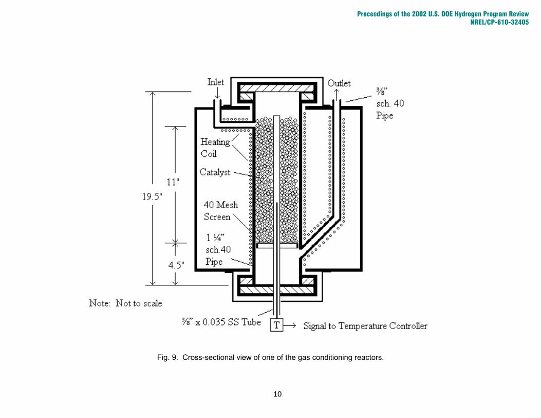
Fig. 9. Cross-sectional view of one of the gas conditioning reactors.
10
Proceedings of the 2002 U.S. DOE Hydrogen Program Review NREL/CP-610-32405

Catalyst is loaded from the top of the reactors, and removed from the bottom, allowing the reactors to be rigidly mounted and the attached tubing permanently installed. This was done to allow for the installation of heated enclosures designed to reduce the risk of exposed electrical connections or extreme temperature surfaces. As a side benefit, the rigidity reduces the potential for leakage due to frequent disassembly. Trace Gas Analysis
The trace contaminant sampling system, illustrated in Figure 10, draws a slipstream from the gas passing into the catalytic reactor system. This sample is drawn following the porous metal filter through which all of the gas passes. The slipstream progresses through a condensing coil to remove all tars. The flow is then split into two smaller streams. The first stream is passed through a Nafion membrane to remove all moisture from the gas, and a sample is drawn with Draeger tubes to quantify hydrogen sulfide (H2S) content. The second stream passes through bubblers plumbed in parallel to each other to simultaneously quantify hydrochloric acid (HCl), hydrogen cyanide (HCN) and ammonia (NH3). Following sampling, these streams are exhausted to atmosphere. Results of work performed on methods for determining hydrogen sulfide (H2S), ammonia (NH3), hydrogen chloride (HCl), and hydrogen cyanide (HCN) in gasifier streams is summarized below. The gas matrix involved greatly complicates these determinations and makes suitable analytical methods difficult to find in some cases. For most of the trace gases of interest, it should be noted that a variety of instrumental methods for on-line analyses are available but are not discussed below. This is because the instruments are either to costly, bulky, or difficult to operate. As one example, an on-line NH3 analyzer based on UV absorption with a photo diode array is available. However, it comes in a 6-foot tall rack and weighs 600 pounds. The unit is also undoubtedly very costly. Such analyzers were avoided because our intent was to establish suitable analytical methods for the analyses of interest that could be performed routinely with a minimum of training, required minimal instrument maintenance, and were cost effective. Analytical approaches considered for each gas of interest are discussed separately below. Hydrogen Sulfide (H2S) A Zellweger Analytics Model 7100 Toxic Gas Monitor was considered for on-line H2S analyses. This method is based on passing sample gas through chemically-impregnated tapes. Presence of the analyte gas causes a color change on the tape, which is then measured by monitoring the reflectivity of the tape. The change in reflectivity is related to analyte concentration. The colorimetric cassette tapes have a short shelf life (typically several months) and cost about $50 for every few days of testing. Excellent linearity and precision are observed (even in the 0-5000 ppb range) when the gas stream conditions (i.e., relative humidity) are constant and the relative humidity (RH) is in the proper range. Also, the method is very sensitive to small changes in H2S levels. There are no significant interferences for the gas streams of interest. The dynamic range is very narrow (e.g., 0-50 ppm) for the “high level” calibration. For the “low level” calibration, the dynamic range is 0-5000 ppb. However, for the “low range” calibration, readings are only statistically meaningful to the second figure (e.g., 1100 ppb versus 1200 ppb). Being able to differentiate between 1000 and 1500 ppb will probably not be an important issue in field testing. At H2S levels of about 50 ppb or less, readings come out only once every 10 minutes, but the data come out more frequently at higher H2S levels. The H2S readings (both high and low calibrations) are very sensitive to the RH of the gas stream, which greatly complicates both calibration and sample analysis.
11
Proceedings of the 2002 U.S. DOE Hydrogen Program Review NREL/CP-610-32405

Flowrate:1.0 L/min
Diaphragm Pump
Exhaust GasDichloromethane
Mini-impinger TrainsFlowrate:
4.5-5.5 L/min Catalytic
Guard Bed
LT Water-
Gas Shift
HT Water-
Gas Shift
CatalyticTar
Cracker Diaphragm Pump
Total Flow MeterHeated
Particulate Filter
Sampling Port
Sampling Port
Sampling Port
Methanol Impinger Train
Gas Bag Sampling Port
Flowrate: 0.5 L/min
Perma-Pure Filter
(80°C) CO, CO2, O2 Analyzer
Required Flowrate:2 L/min
Diaphragm Pump
H2S Draegger Tube Port
Condensing Coil (100°C) Exhaust Gas
H2 AnalyzerRequired Flowrate:
1 L/min Flowrate: 1.0 L/min
NH3 Bubblers Flow Switch Exhaust Gas
Diaphragm Pump HCl Bubblers Exhaust Gas
HCN Bubblers
Fig. 10. Detail of slipstream showing trace contaminant sampling system.
12
Proceedings of the 2002 U.S. DOE Hydrogen Program Review NREL/CP-610-32405

The RH of the calibration gas must match (very closely) the RH of the sample gas. For acceptable accuracy, the RH must be within about 10% RH (absolute) of the optimum RH. Also, the optimum RH is sensitive to the H2S concentration as well as some instrumental variables. The analyzer does an excellent job under some sets of conditions, but does not do very well under other sets of conditions. This analyzer is probably best used to simply detect the presence of H2S (and trigger a built-in audible and/or visual alarm if desired) and to track relative H2S concentrations at a specific (controlled) RH level in the sample gases. The overall utility of this method is considered marginal for the accurate determination of H2S in the application of interest. Water solutions could potentially be used to collect H2S (very water soluble), with subsequent analysis by ion chromatography (IC). However, the manufacturer of our IC believes it would be very risky to introduce our aqueous samples into the IC because of significant levels of water-soluble organics (light hydrocarbons) in our samples that could cause problems (including damaging system components) in the IC. A variety of titrimetric procedures are available, but have not been explored. An ion selective electrode looks like an attractive alternative to ion chromatography, since it is highly specific and very sensitive. However, sulfide tends to be very unstable in solution and is difficult to preserve. Better options are available for this determination. In particular, direct gas stream analyses using Draeger tubes (discussed below) appear to be very promising. Bubbling gases into a lead acetate solution to form lead sulfide produced promising results. After a sampling time of only 2 minutes in the laboratory, 10 ppm H2S could easily be detected due to the decrease in sample transmittance from the formation of microcrystalline lead sulfide (black). However, the lead solutions are a hazardous waste, and direct gas stream analyses are preferred to wet chemical approaches. Draeger tubes appear to work well, and they are currently the method of choice for this analysis in view of cost considerations and the desired frequency of analysis. The tubes are typically accurate to within about 25%, and there is no sensitivity to relative humidity (a major advantage over the chemcassettes used with the Zellweger analyzer). Readings are very linear with H2S concentration. For the sample streams of interest, there do not appear to be any significant interferences. Organic vapors in the sample gas have little or no effect on the H2S reading, and the organic vapors themselves do not give a reading. Because of gas density issues, the H2S reading will be about 1% too high for each percentage of hydrogen in the gas stream. The tubes cost about $5 each and typically have a shelf life of 2-3 years (as opposed to several months for the Zellweger cassettes). When sampling gasifier streams for H2S analysis, moisture condensation upstream from the analysis point must be avoided because H2S is very water-soluble. In the sampling scheme envisioned at this time, particulate matter will first be removed with a high-temperature filter at about 400°C. Next, heavy tars will be removed by condensation at 100°C. To condense the tars without the use of an impinger train, a modified pressure cooker has been developed but not yet tested. Water will be boiled in the pressure cooker to provide a constant temperature of 100°C. Gases entering the vessel will first enter a large stainless steel beaker. This will greatly reduce the gas velocity and initiate the dropout of tars. The gases will then exit the beaker and pass through a stainless steel coil (inside the pressure cooker) consisting of about 12 feet of 3/8-inch OD tubing. This is intended to provide enough residence time at 100°C to complete the removal of heavy tars. The ID of the steel tubing is sufficient that the tars are not expected to plug the lines during a given sampling run (but may require rinsing out with dichloromethane prior to each sample run). Because H2S tends to be reactive with steel, all of the steel in the pressure cooker that contacts the sample
13
Proceedings of the 2002 U.S. DOE Hydrogen Program Review NREL/CP-610-32405

has been coated with several microns of amorphous silica. After heavy tar removal, the sample gases will pass through a heated Perma Pure drier. The Perma Pure cannot be operated in the normal manner (i.e., heated only to the Perma Pure inlet) because too many light hydrocarbons are likely to condense out and plug the walls of the Perma Pure. Therefore, a heated Perma Pure (housed in an oven) will be used. Heating will prevent many of the light hydrocarbons from condensing out, but will also result in incomplete drying of the gas stream. In fact, the moisture dew point may be as high as 50-60°C. This introduces a moisture variable from test to test, and the Draeger tube results will be affected somewhat (no more than 10%) by variable moisture contents on the partially dried sample gases. Heated Draeger tubes could potentially be used to avoid this problem. However, according to manufacturer specifications, the Draeger tubes should not be used above 40°C. At higher temperatures, the chemicals can be affected and lead to erroneous results. With all the additive uncertainties in the analysis, the readings from the Draeger tube may be accurate to within only about 40% (probably the worst case). However, tracking of relative H2S concentrations should be reliable if good sampling techniques are utilized. Other instrumental approaches are possible for continuous, on-line H2S measurements. H2S measurements in gasifier streams are typically determined by gas chromatography fitted with a suitable detector. Also, several vendors of alternate technologies have verbally agreed to free instrument loans so we can evaluate the analyzers for our specific applications. However, purchasing one of those instruments would cost $10-15K. Since the Draeger tubes appear to work well, are very versatile, and cost only about $5 per test, the Draeger tubes are probably still the method of choice at this time. The transport of H2S through a Perma Pure drier was investigated. When using a 2 ppm H2S stream at a flow rate of about 1 L/min, the H2S was successfully passed through the drier (i.e., all the H2S was retained in the sample gas). This was true for countercurrent purge flow rates of 2 and 10 L/min. On another sample transport issue, blending 10 ppm or 250 ppb H2S with 1000 ppm NH3 did not affect the H2S levels (i.e., the NH3 and H2S did not react to form ammonium sulfide compounds). During laboratory testing, no significant wall effects were observed when H2S was passed through Teflon lines at room temperature, even for H2S in the 0-5000 ppb range. Laboratory tests showed that a stream of 25 ppm H2S (in nitrogen) could be successfully transported through stainless steel (type 316) lines at 25 and 200°C. However, major H2S losses were observed at 400°C. Using electropolished stainless steel or superalloy Inco Alloy C276 did not help at that temperature. However, using stainless steel with an interior coating of amorphous silica solved the sample transport problem at 400°C. It is recommended that all sample transport lines and other sampling components above 200°C be made of Silcosteel. Below that temperature, Teflon should be used to help ensure effective sample transport over a wider range of H2S concentrations. Hydrogen Cyanide (HCN) HCN is the most difficult trace gas of interest to determine. With the Zellweger dry colorimetric analyzer, the manufacturer notes that the detection tapes for HCN are some of the worst tapes with respect to RH sensitivity, and also for the problem of the optimum RH being dependent on the analyte concentration. In other words, the tape (instrument reading) is very sensitive to RH, but the optimum RH that must be used to get accurate readings depends on the HCN concentration, which is not known without analyzing the gas stream. The signals obtained with
14
Proceedings of the 2002 U.S. DOE Hydrogen Program Review NREL/CP-610-32405

the HCN tape had an RSD of 15% for a 50 ppm HCN stream. This uncertainty (which in itself is very acceptable) must be combined with the large uncertainties due to the effects of RH. In addition, H2S is an interference. With H2S in nitrogen, it takes 5-10 ppm H2S to give a reading of 1 ppm HCN. However, according to the manufacturer, when both HCN and H2S are present, the H2S is a negative interference rather than a positive interference. In other words, H2S alone gives a false positive signal, but when H2S is combined with HCN, the H2S actually leads to signal suppression. Thus, there are numerous problems in using this particular analytical approach. The H2S can be removed by using a scrubber (based on lead acetate) from the vendor. However, it would cost about $100 a day to use their nonregenerable scrubbers. We can make our own for about $5 each, but in view of all the other analytical uncertainties, which provide semiquantitative analyses at best, it is probably best to simply analyze the unscrubbed gases. The analyses would only be semiquantitative and could be used (if desired) to indicate the absence or presence of significant levels of HCN. As with the other water-soluble species, HCN can probably not be done by IC because of the problems from water-soluble organics. Also, Draeger tubes cannot be used because gases such as CO and H2 are major interferences, and it would be difficult to remove those gases without affecting trace levels of HCN. UV or visible light absorption won't work because HCN has no significant absorption bands in those regions. The use of ion selective electrodes is possible, but suffers from severe interferences from sulfide and chloride ions. The sulfide can easily be removed by adding lead carbonate. The effect of lead carbonate on chloride removal is uncertain at this time. Cyanide could potentially be determined by analyzing aqueous condensates or impinger solutions used to sample effluent gases. A variety of wet chemical methods are available for cyanide determination in aqueous samples, including the use of colorimetric and titrimetric procedures. If sulfides are present, sample distillation is required prior to analysis because sulfides interfere with the determination. This would make the overall procedure more complex and increases chances of sample contamination through additional sample handling. Sampling and analysis of cyanide is inherently difficult because of poor sample stability. A variety of sample pretreatment steps may be required to properly preserve the samples prior to analysis. A fluorometric method for determining cyanide in aqueous solutions will be tested, since that method is reportedly highly sensitive and very selective. Although there are essentially no chemical interferences, the presence of sulfide causes an analytical error due to a decrease in the pH of the sample. This problem can be avoided by checking the pH of the sample solutions. If the pH is indeed a problem, then a phosphate buffer can be used to eliminate the problem. The necessary optical kit for the fluorometric determination of HCN has been received and installed in the fluorometer. In addition, all the necessary chemicals and peripheral supplies have been ordered and received. If the method appears promising after laboratory testing, it must be noted that cyanide samples degrade very quickly, and analyses should be performed immediately. Difficulties in working with cyanide in solution require immediate sample preservation. In addition, immediate sample pretreatment (prior to sample preservation) to remove sulfide may be required, since sulfide quickly converts cyanide to thiocyanate (SCN). If these steps are not taken, it has been reported that the rate of cyanide loss can be as high as 50% per hour. In studies on the transport of HCN through a Perma Pure drier, a 100 ppm HCN stream flowing at about 1 L/min could be successfully passed through the drier. This held true while using purge gas flow rates of 0, 2, and 10 L/min.
15
Proceedings of the 2002 U.S. DOE Hydrogen Program Review NREL/CP-610-32405

The transport of a 60 ppm HCN stream (in nitrogen) was studied using stainless steel and Teflon sample lines. Laboratory tests showed that HCN could be successfully transported through stainless steel (type 316) lines at 25, 200, and 400°C. Thus, it does not appear to be necessary to use Silcosteel for transport of HCN in the temperature range and HCN concentration range of interest. Ammonia (NH3) The Zellweger analyzer was tested for its suitability for performing NH3 analyses. There were no interferences from most matrix gases. However, because of a severe interference from CO (not in the literature from the vendor) at the CO levels anticipated for gasifier streams, this method is unsuitable for NH3 analyses in gasifier streams. Even if the CO was not a problem, the instrument reading was strongly influenced by the RH of the gas stream, as appears to be the case with all the detection tapes for this analyzer. A fluorometric method for the determination of NH4 (NH3 in water produces NH4) in aqueous solutions was investigated and is very promising. The method is based on reacting NH4 with orthophthaldialdehyde to form a highly fluorescent compound, which is then measured with a fluorometer. An “incubation period” of about 2 hours is required prior to analysis. The fluorometer is not much larger than a toaster, requires virtually no maintenance, and is very simple to use. The approach was studied in the laboratory and was found to be extremely sensitive, with a detection limit of less than 1 ppb in solution. Under the conditions studied, the linear range was from about 0-200 ppb. Based on analyses of some actual field samples (aqueous condensates) obtained during biomass gasification, autofluorescence (fluorescence of the matrix itself) was not a problem. The severity of any matrix effects requires investigation. As an alternative to the fluorometric determination of NH4 in aqueous solutions, the use of a specific ion electrode appears promising (but has not yet been tested). There do not appear to be any significant interferences for the sample matrices involved. Also, it is very sensitive, with a detection limit of about 10 ppb in solution. The advantage of this approach over the fluorometric method is that the determination can be made immediately (i.e., no “incubation time” is required). The use of Draeger tubes for performing NH3 determinations was explored. Tubes are available for NH3 concentrations ranging from 0.5 ppm to 1% or more. The manufacturer notes that results are unaffected by relative humidities between 20 and 90%. No correction factors are required for middle range tubes (10-1000 ppm), but a correction factor is required for the low range tube (0.5-80 ppm) if the concentration reading is above 30 ppm. There do not appear to be any significant interferences from other gases in the anticipated sample gas matrix. However, tar vapors (atmosphere above dichloromethane containing dissolved tars) give a substantial positive response with the Draeger tubes. Vapors from pure dichloromethane do not give any response in themselves. It is possible that the dichloromethane contains a portion of the total NH3 content of the sampled gas stream, and that the positive NH3 responses obtained when sampling vapors above the tar-containing dichloromethane are actually real. To explore this possibility, vapors above a tar sample (in dichloromethane) were swept into a bubbler containing deionized water as the absorbing solution. The absorbing solution was then analyzed by ion chromatography (IC). The IC results indicated that significant amounts (15 times above blank levels) of NH4 were present in the absorbing solutions. In related work, vapors were analyzed directly above a fresh tar sample (tars in dichloromethane) after first removing the aqueous phase with suction. The tar sample was then washed twice by adding a small amount of water, shaking vigorously, and once again removing the aqueous fraction.
16
Proceedings of the 2002 U.S. DOE Hydrogen Program Review NREL/CP-610-32405

Vapors above the tar sample were analyzed after each wash. Results of the analyses with the Draeger tubes indicated that the reading above the tar sample was reduced by more than 90% after the first wash. The reading obtained after the first wash was reduced by about 90% after the second wash. Thus, it appears that the tar samples either contain small amounts of aqueous phase (containing NH3) within the sample, or else the NH3 has some solubility in the dichloromethane and is washed out with water. Although Draeger tubes appear to work well overall in the laboratory using simple gas matrices, there is still the issue of NH3 and HCl combining as the gases cool, with the subsequent formation and possible deposition of ammonium chloride. Also, according to recommendations from the manufacturer, the tubes should not be used above 40°C. Because NH3 is not effectively transported through a Nafion dryer (see discussion below), the analyses must be performed prior to the drier, in which case the moisture content of the gas stream will be extremely high. In addition, the temperature of the gases entering the Nafion is at about 100°C, which greatly exceeds the recommended temperature range. Because of these complications, Draeger tubes do not appear to be well suited for direct analysis of gasifier streams. In tests on the transport of NH3 through a Perma Pure drier, a humidified stream of 500 ppm NH3 flowing at about 1 L/min could not be passed through a laboratory-scale Perma Pure system. In fact, there was no trace of NH3 in the sample gases exiting the drier, even though the NH3 level entering the drier was 10 times the amount necessary for the analyzer to read off-scale. The countercurrent purge gas stream (flowing at 2 and 10 L/min) was also analyzed for NH3, but none was detected. The Nafion tubing in the Perma Pure drier contains sulfonic acid groups, and it is likely that those sulfur-containing species are reacting with the NH3. This shows that a Perma Pure drier can probably not be used for field sampling of NH3 from gasifiers. In addition, the coexistence of NH3 and HCl would lead to the formation of solid ammonium chloride if the gas temperatures are allowed to cool to near room temperature. On the transport of NH3 in steel sample lines, laboratory tests showed that 60 ppm NH3 (in nitrogen) could be successfully transported through stainless steel (type 316) lines at 25, 200, and 400°C. Thus, it does not appear to be necessary to use Silcosteel for transport of NH3 in the temperature range and concentration range of interest. Hydrogen Chloride (HCl) As noted above for H2S, the colorimetric cassette tapes for the Zellweger analyzer have a short shelf life (typically several months) and cost about $50 for every few days of testing. There are currently three separate HCl calibrations loaded into our Zellweger analyzer, which are: 1) high-level (0-50 ppm); 2) high-level with low humidity; and 3) low-level (0-5000 ppb) HCl. The low-level HCl analysis should not be used in the field with this analyzer. The long response time (up to 10 minutes) for this tape limits its usefulness, particularly when combined with the stringent humidity requirements (40-60% RH) and sample transport difficulties in the ppb range. In addition, this tape is more susceptible to chemical interferences than the high-level HCl tape. For the high-level tape, the accuracy seems questionable when using humidified gas streams. Those analyses are greatly affected by the RH of the sample gas. For example, the signal obtained for a 20 ppm HCl gas stream is ten times higher at 60% RH than at 80% RH. The acceptable humidity range of 40-60% is very narrow. Also, the narrow analytical range of only 0-50 ppm HCl limits its usefulness. When using the dry HCl calibration with dry HCl streams, the instrument readings tracked well with changes in HCl concentration, and a linear response was observed over the analytical range of the instrument. For a 40 ppm HCl stream (dry), the RSD for multiple readings was only about 5%. Although better results were obtained with dry
17
Proceedings of the 2002 U.S. DOE Hydrogen Program Review NREL/CP-610-32405

gases than with humidified gases, the analytical range is still only 0-50 ppm. Also, dry gases cannot be easily attained without losing gaseous HCl unless large gas stream dilutions with dry gases are used (drying with the Perma Pure is not very effective since it must be operated at elevated temperatures to keep most of the light hydrocarbons in the vapor phase). Laboratory tests using humidified HCl streams with the high level HCl tape showed that this particular tape is very specific. However, contrary to what was reported by the vendor, in-house laboratory tests indicated that H2S is an interference. At 50% RH, a 100 ppm H2S stream gave a reading of about 15 ppm. Thus, there is roughly a 7:1 rejection ratio for H2S based on these tests. Although this might at first appear to be only a minor interference, it must be kept in mind that gasifier streams could have H2S levels that are much higher (e.g., five-fold or more) than the HCl concentrations, in which case it would be a major interference. Although HCN and NH3 are not chemical interferences (do not give a reading in themselves), the vendor notes that either one of those gases can desensitize the HCl tape and result in lowered readings for HCl. After considering all the information noted above, this method does not appear to be a good analytical choice for determining HCl in gasifier streams. It is unlikely that the analyzer can be used to detect the presence of HCl and trigger an internal alarm if HCl is detected. In order to serve as an alarmed qualitative HCl sensor, the NH3 in the gas stream would have to be preferentially removed. Otherwise, the chloride will be converted to ammonium chloride as the gases cool prior to entering the analyzer. In addition, there cannot be any condensed moisture as the gases cool to near room temperature. Cooling the gases without forming any condensed moisture would most likely require substantial gas stream dilution with a dry gas. Water solutions could potentially be used to collect HCl (very water soluble), with subsequent analysis by IC. However, the same comments noted for H2S apply here as well. In particular, there are concerns about the effects of dissolved organic compounds on IC system components. Nonetheless, others have reported using this approach for similar analyses, and it is an option we are still considering for this particular trace gas species. If the concentration of dissolved organics in the solutions to be analyzed can be lowered to the ppm level through suitable sampling or sample processing procedures, it might be a good analytical method for performing the HCl determinations. One potential sampling method that is being considered involves injecting halogen-free water into the sample gas stream. This could potentially remove all the HCl without leading to the formation of solid NH4Cl. In addition to using IC for analyzing aqueous solutions for HCl, other analytical approaches were also considered. Ion selective electrodes do not appear promising for determining HCl in collection solutions because sulfide and cyanide ions (among others) strongly interfere. A variety of spectrophotometric and titrimetric procedures could potentially be used and are being considered further. Draeger tubes work well overall. The tubes are typically accurate to within about 25% in a simple gas matrix (e.g., air). Tubes are available for HCl concentrations of 0.2 to 75 ppm and 10-1000 ppm. The tubes for the lower range require a correction factor for concentrations between 20 and 75 ppm, while no corrections are required for the higher range tube. The tube readings track well with changing HCl concentration. For the sample streams of interest, there do not appear to be any significant interferences. HF is only a minor interference, with a “rejection ratio” of between 10:1 and 20:1. Although NH3 alone (no HCl) gives a positive reading, this occurs only at NH3 concentrations above about 1%. Since NH3 levels should always be well below this in biomass gasification streams, the presence of NH3 should not result in any false positive readings. However, several problems preclude their use for reliable direct gas stream analysis. Work with tar vapors (atmosphere over tars in dichloromethane) indicated that those vapors appear to suppress the HCl reading significantly. When a sample of tar
18
Proceedings of the 2002 U.S. DOE Hydrogen Program Review NREL/CP-610-32405

vapors was first drawn through the Draeger tubes, followed by using the same tube for analyzing HCl streams, HCl readings were suppressed by 30-60% relative to readings taken without prior exposure to tar vapors. Problems were also encountered when noncondensed moisture was present in the gas stream. When a nitrogen stream was blended with HCl to give a 30 ppm HCl stream, followed by analysis with Draeger tubes, accurate readings were obtained when using dry gases. However, when the gas stream was at 75% relative humidity (nitrogen was humidified prior to blending with dry HCl), the readings on the Draeger tubes were reduced by 50%, even after equilibrating the gas stream for over an hour. This conflicts with printed information from the manufacturer, which states that there is no sensitivity to relative humidity between 0 and 90% RH. However, the results discussed here were very reproducible, and the tests were performed very carefully. In view of the issues with moisture and tar vapors, Draeger tubes do not appear to be well suited for direct analysis of gasifier streams for HCl. A variety of instrumental approaches are possible for continuous, on-line HCl measurements. For example, for HCl levels of 1 ppm or higher, gas filter correlation IR might be a good choice. The gas stream would have to be combusted to eliminate the severe interference from methane, and this would remove the troublesome NH3 (combines with HCl upon cooling to form solid ammonium chloride) as well. At least one instrument vendor for that technology has verbally agreed to a free instrument loan so we can evaluate the analyzer for our specific applications. However, purchasing one of those instruments would cost $10-15K, and other methods will be explored before considering this option further. Another possibility is ion mobility spectroscopy (IMS), which is an atmospheric time-of-flight analyzer. However, it is more difficult to operate and maintain than IR-based analyzers. In work performed previously in our laboratories using IMS, catalytic oxidation of simulated gasifier streams was employed to destroy hydrocarbons and NH3, which made detection of HCl relatively simple. However, a variety of technical issues still remain before that approach can be used routinely. Although we currently have an IMS analyzer for HCl, it needs repairs. Also, the range is only 0-20 ppm, which necessitates using gas stream dilution and then correcting the HCl concentration back to the original (undiluted) gas stream. Nonetheless, it could potentially be used. A new IMS analyzer (which could be made with a range of 0-100 ppm) would cost on the order of $25K, so purchasing a new unit may not be a viable option at this time. Tests were performed to determine whether low levels of HCl could be successfully transported through a Perma Pure drier. A 45 ppm HCl stream (humidified) flowing at about 1 L/min was passed into a small, laboratory-scale Perma Pure drier. Gases exiting the drier were analyzed continuously with the Zellweger Toxic Gas Monitor. Purge gas flow rates of 10 and 20 L/min were tested. Results of the tests indicated that the HCl stream could be passed through the drier without any detectable losses of HCl from the sample gas. As another sample transport issue, the effects of blending NH3 with HCl on the HCl concentration was examined. If gases are allowed to cool too much, ammonium chloride may form and deposit as a solid powder. In addition to potentially clogging sample transport lines, this obviously constitutes a loss of analyte. When a stream of 50 ppm HCl was blended with 50 ppm NH3, the HCl readings on the Zellweger analyzer disappeared within several minutes. The HCl readings were fully restored within minutes after shutting off the NH3 flow. Similarly, in work with Draeger tubes, blending 0.2% NH3 with a stream of 100 ppm HCl reduced the HCl readings to nearly zero. The temperature necessary to prevent the formation of ammonium chloride varies, depending on the absolute and relative concentrations of NH3 and HCl in the gas stream. The formation of ammonium chloride remains an area of concern, regardless of what sampling/analytical technique is used.
19
Proceedings of the 2002 U.S. DOE Hydrogen Program Review NREL/CP-610-32405

Since HCl can be successfully passed through a Nafion dryer, while NH3 appears to be completely retained by the dryer (see section on NH3), the possibility was considered that the dryer could potentially be used as a filter to preferentially remove NH3. This would eliminate the problems associated with NH3 and HCl coexisting in the gas stream. To test this possibility, a gas stream containing about 50 ppm HCl and 1200 ppm NH3 was passed through a Nafion dryer heated at 110°C (the Nafion temperature being used in field sampling) in a convection oven. The NH3 was introduced to the HCl stream inside the oven just prior to the Nafion. Gases exiting the dryer were analyzed continuously for HCl using the Zellweger analyzer. Results of the tests showed that HCl could not be passed through the dryer when NH3 was present. This has important gas sampling implications because direct HCl analyses on the gas stream can probably not be performed downstream from a Nafion dryer if NH3 coexists with the HCl. The high moisture content of the gas stream prior to drying precludes the use of most analytical approaches for direct gas stream analyses. The best low-cost approaches will probably involve either diluting the sample gases with a dry gas stream prior to direct gas HCl analysis, or performing off-line analyses after collecting HCl in absorbing solutions (or possibly analyzing aqueous condensate formed as the gases are cooled to below room temperature). Tests were also performed to study the transport of HCl through various types of sample lines. A nitrogen stream containing about 50 ppm HCl was used. Materials tested were PFA Teflon, 316 stainless steel, electropolished stainless steel, Silcosteel, and superalloy Inco Alloy C276. Sample transport in the 316 stainless steel was poor at room temperature, and was somewhat better with the Inco Alloy C276. However, at room temperature, the HCl stream was transported effectively when using Silcosteel or the electropolished stainless steel (electropolishing greatly reduces surface area and provides a chromium enrichment on the surface). In both of those cases, sample transport appeared to be nearly as effective as when using Teflon tubing. At temperatures of 200 and 400°C, the HCl was effectively transported in all the metal lines tested. Therefore, as with NH3 and HCN (but unlike H2S), Silcosteel is probably not necessary for effectively transporting HCl at the 50 ppm level. However, sample lines below 200°C should be made of Teflon or Silcosteel. As was the case with the other gases tested, only nitrogen was used as the carrier gas. It is possible that different results could be observed when using a more complex gas matrix (i.e., closer to a real gasifier stream) that provides a highly corrosive environment.
FUTURE WORK
Construction of the experimental system is nearly complete. Some plumbing of the gas conditioning system and the steam delivery system has yet to be completed, and final selection of an analytical method for chlorine has not been made, but otherwise, design, fabrication, and assembly are complete. Shakedown trials of the gasifier operating in conventional mode and ancillary equipment commenced in mid April. A few minor leaks in producer gas lines were detected and corrected, but otherwise, systems performed as expected. Experimental trials of the gasifier operating in ballasted mode will probably commence in mid May. These tests will determine the feasibility of converting switchgrass into a hydrogen-rich gas stream. Optimization of the gas conditioning system will be performed. The cost of hydrogen from switchgrass will be estimated.
20
Proceedings of the 2002 U.S. DOE Hydrogen Program Review NREL/CP-610-32405