bi-xenon headlights with afs - audi news and … headlights with afs ... the 2012 audi a7 onboard...
TRANSCRIPT
41
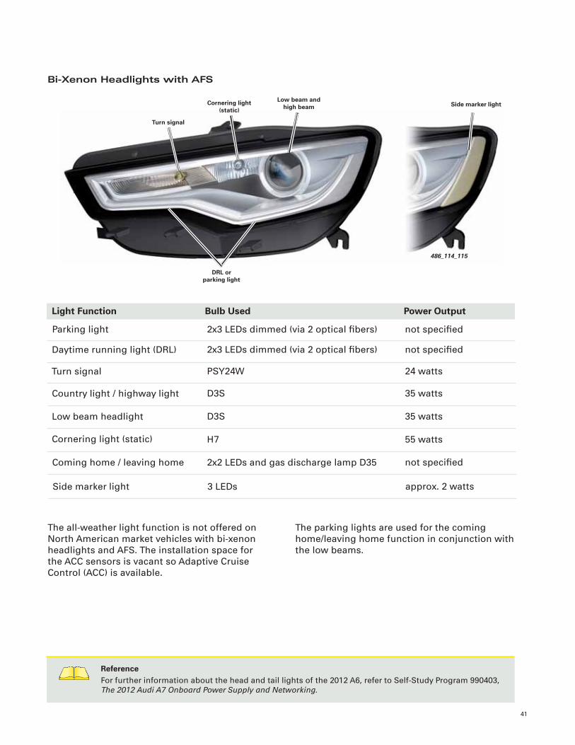
Bi-Xenon Headlights with AFS
The all-weather light function is not offered on North American market vehicles with bi-xenon headlights and AFS. The installation space for the ACC sensors is vacant so Adaptive Cruise Control (ACC) is available.
486_114_115
Turn signal
DRL or parking light
Low beam and high beam Side marker lightCornering light
(static)
Light Function Bulb Used Power Output
Parking light
Daytime running light (DRL)
Turn signal
Low beam headlight
Cornering light (static)
2x3 LEDs dimmed (via 2 optical fi bers)
2x3 LEDs dimmed (via 2 optical fi bers)
PSY24W
D3S
H7
not specifi ed
not specifi ed
24 watts
35 watts
55 watts
Country light / highway light D3S 35 watts
Coming home / leaving home 2x2 LEDs and gas discharge lamp D35 not specifi ed
Side marker light 3 LEDs approx. 2 watts
The parking lights are used for the coming home/leaving home function in conjunction with the low beams.
ReferenceFor further information about the head and tail lights of the 2012 A6, refer to Self-Study Program 990403, The 2012 Audi A7 Onboard Power Supply and Networking.
42
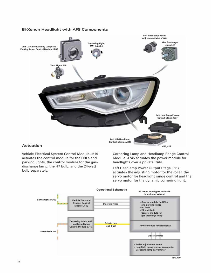
Bi-Xenon Headlight with AFS Components
486_033
Turn Signal M5
Left HID Headlamp Control Module J343
Left Daytime Running Lamp and Parking Lamp Control Module J860
Left Headlamp Beam Adjustment Motor V48
Gas Discharge Lamp L13
Cornering Light M51 (static)
Left Headlamp Power Output Stage J667
486_100
Discrete wires
Bi-Xenon headlights with AFS(one side of vehicle)
Vehicle Electrical System Control
Module J519
Cornering Lamp and Headlamp Range
Control Module J745
– Control module for DRLs and parking lights– H7 bulb– 24 watt bulb– Control module for gas discharge lamp
Operational Schematic
Private bus (sub-bus) Power module for headlights
Convenience CAN
Extended CAN
Discrete wires
– Roller adjustment motor– Headlight range control servomotor– Cornering lamp servomotor
Cornering Lamp and Headlamp Range Control Module J745 actuates the power module for headlights over a private CAN.
Left Headlamp Power Output Stage J667 actuates the adjusting motor for the roller, the servo motor for headlight range control and the servo motor for the dynamic cornering light.
Actuation
Vehicle Electrical System Control Module J519 actuates the control module for the DRLs and parking lights, the control module for the gas-discharge lamp, the H7 bulb, and the 24-watt bulb separately.

43
LED Headlights
The LED headlights of the A6 feature LEDs for lighting functions. Each headlamp has a total of 57 LEDs together with accompanying heat sinks. A fan integrated into the headlight prevents the electronic components from overheating.
Light Function LEDs Used
Parking light
Daytime running light (DRL)
Turn signal
High beam headlight
Cornering light (static)
LEDs (white, dimmed)
LEDs (white)
2x2 LEDs
12 LEDs (3x4 chip, in addition to low beams)
4 LEDs (1x4 chip, in addition to low beams)
Low beam headlight 14 LEDs (5x2 chip and 4 single LEDs)
Coming home / leaving home 14 LEDs (5x2 chip and 4 single LEDs)
Side marker light 3 LEDs (white with yellow refl ector)
Refl ectors or projection modules are used, depending on the lighting function. Thick-walled optics are employed for the DRLs, parking lights, and turn signals to achieve a homogenous appearance for these lighting functions.
486_030_049
High beam
Low beam (symmetrical)
Low beam (asymmetrical) Side marker light
Cornering light (static)
44
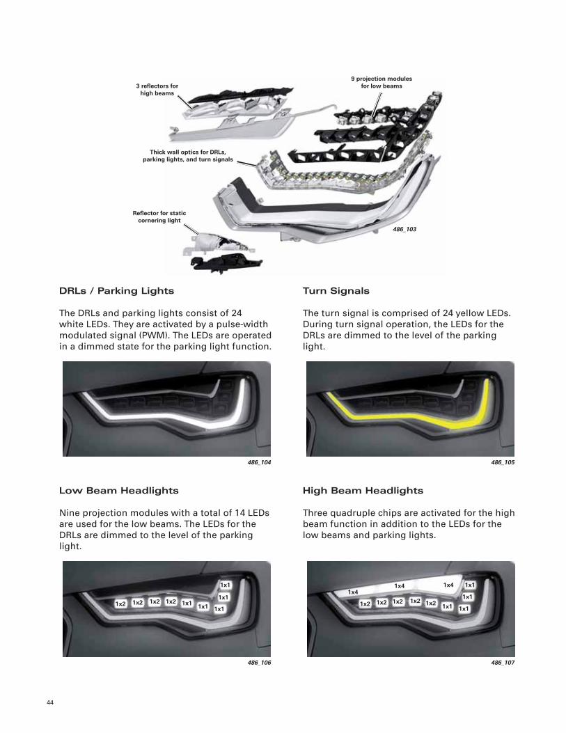
DRLs / Parking Lights
The DRLs and parking lights consist of 24 white LEDs. They are activated by a pulse-width modulated signal (PWM). The LEDs are operated in a dimmed state for the parking light function.
Turn Signals
The turn signal is comprised of 24 yellow LEDs. During turn signal operation, the LEDs for the DRLs are dimmed to the level of the parking light.
Low Beam Headlights
Nine projection modules with a total of 14 LEDs are used for the low beams. The LEDs for the DRLs are dimmed to the level of the parking light.
High Beam Headlights
Three quadruple chips are activated for the high beam function in addition to the LEDs for the low beams and parking lights.
486_103
3 refl ectors for high beams
9 projection modules for low beams
Refl ector for static cornering light
Thick wall optics for DRLs, parking lights, and turn signals
486_104 486_105
486_106
1x2 1x2 1x2 1x2 1x1 1x1 1x1
1x1
1x1
486_107
1x41x41x4
1x2 1x2 1x2 1x2 1x2 1x1 1x1
1x1
1x1
45
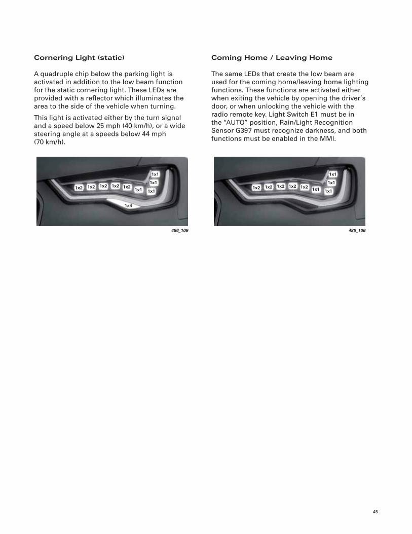
Cornering Light (static)
A quadruple chip below the parking light is activated in addition to the low beam function for the static cornering light. These LEDs are provided with a refl ector which illuminates the area to the side of the vehicle when turning.
This light is activated either by the turn signal and a speed below 25 mph (40 km/h), or a wide steering angle at a speeds below 44 mph(70 km/h).
Coming Home / Leaving Home
The same LEDs that create the low beam are used for the coming home/leaving home lighting functions. These functions are activated either when exiting the vehicle by opening the driver’s door, or when unlocking the vehicle with the radio remote key. Light Switch E1 must be in the “AUTO” position, Rain/Light Recognition Sensor G397 must recognize darkness, and both functions must be enabled in the MMI.
486_106
1x2 1x2 1x2 1x2 1x2 1x1 1x1
1x1
1x1
486_109
1x2 1x2 1x2 1x2 1x21x1 1x1
1x1
1x1
1x4
46
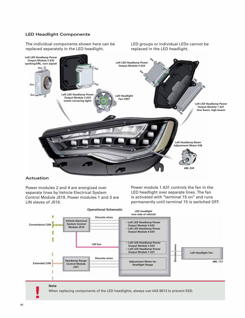
LED Headlight Components
The individual components shown here can be replaced separately in the LED headlight.
LED groups or individual LEDs cannot be replaced in the LED headlight.
486_034
Left LED Headlamp Power Output Module 2 A32
(parking/DRL, turn signal)
Left Headlight Fan V407
Left LED Headlamp Power Output Module 3 A33(static cornering light)
Left LED Headlamp Power Output Module 4 A34
Left LED Headlamp Power Output Module 1 A31
(low beam, high beam)
Left Headlamp Beam Adjustment Motor V48
Actuation
Power modules 2 and 4 are energized over separate lines by Vehicle Electrical System Control Module J519. Power modules 1 and 3 are LIN slaves of J519.
Power module 1 A31 controls the fan in the LED headlight over separate lines. The fan is activated with “terminal 15 on” and runs permanently until terminal 15 is switched OFF.
486_113
Discrete wires
LED headlight(one side of vehicle)
Vehicle Electrical System Control
Module J519
Headlamp Range Control Module
J431
– Left LED Headlamp Power Output Module 2 A32– Left LED Headlamp Power Output Module 4 A34
Operational Schematic
Left Headlight Fan
Convenience CAN
Extended CAN
Dis
cret
e w
ires
Discrete wires
LIN bus – Left LED Headlamp Power Output Module 3 A33– Left LED Headlamp Power Output Module 1 A31
Adjustment Motor for Headlight Range
NoteWhen replacing components of the LED headlights, always use VAS 6613 to prevent ESD. !
47
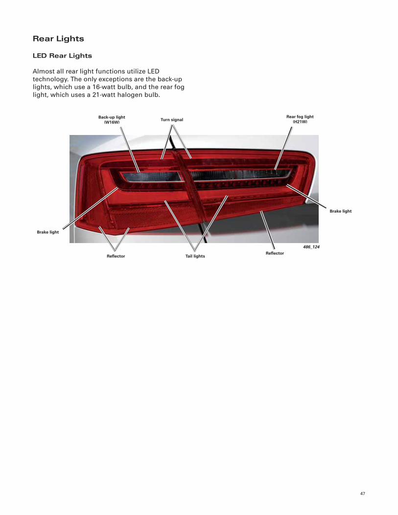
Rear Lights
LED Rear Lights
Almost all rear light functions utilize LED technology. The only exceptions are the back-up lights, which use a 16-watt bulb, and the rear fog light, which uses a 21-watt halogen bulb.
486_124
Back-up light (W16W) Turn signal
Refl ector
Brake light
Tail lights
Rear fog light (H21W)
Brake light
Refl ector
48
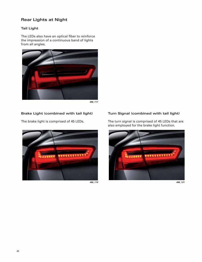
Rear Lights at Night
Tail Light
The LEDs also have an optical fi ber to reinforce the impression of a continuous band of lights from all angles.
Brake Light (combined with tail light)
The brake light is comprised of 45 LEDs.
Turn Signal (combined with tail light)
The turn signal is comprised of 45 LEDs that are also employed for the brake light function.
486_117
486_121486_119
49
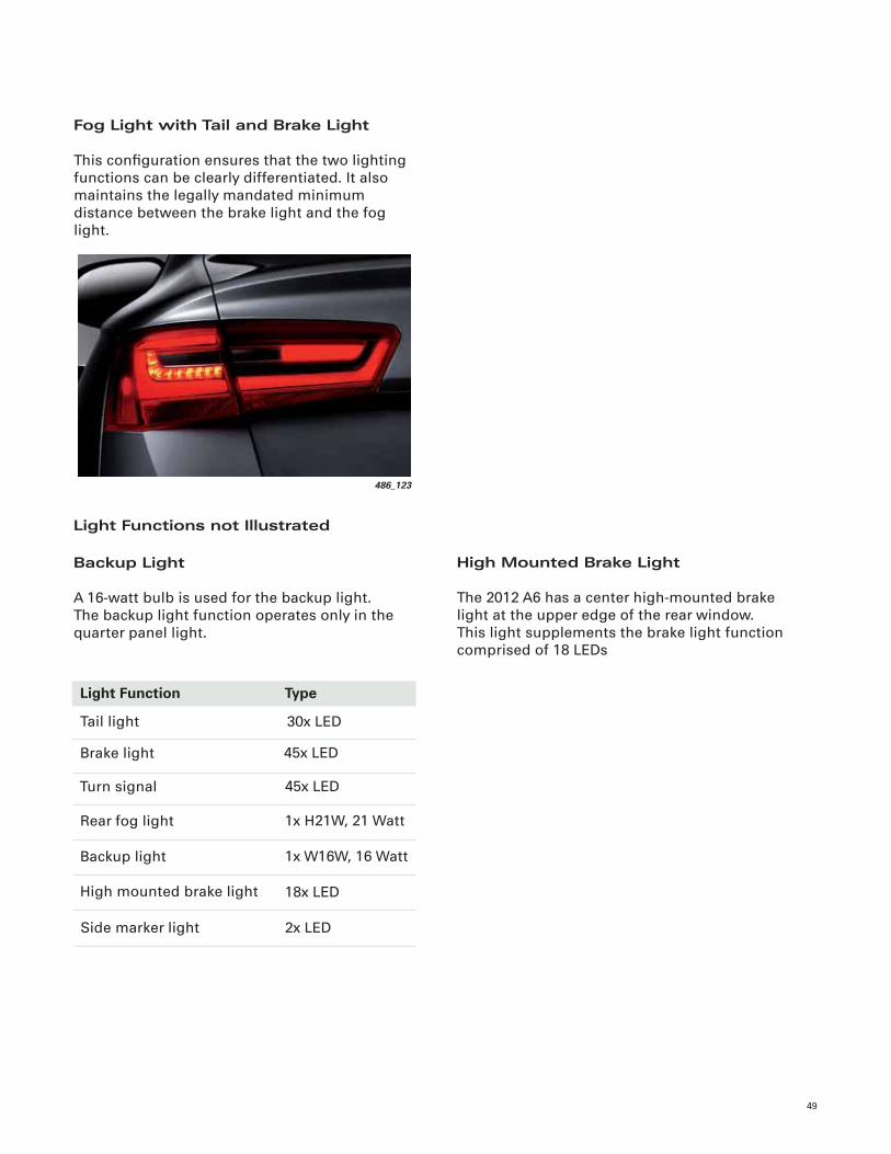
Fog Light with Tail and Brake Light
This confi guration ensures that the two lighting functions can be clearly differentiated. It also maintains the legally mandated minimum distance between the brake light and the fog light.
Light Functions not Illustrated
Backup Light
A 16-watt bulb is used for the backup light. The backup light function operates only in the quarter panel light.
486_123
High Mounted Brake Light
The 2012 A6 has a center high-mounted brake light at the upper edge of the rear window. This light supplements the brake light function comprised of 18 LEDs
Light Function Type
Tail light
Brake light
Turn signal
Backup light
High mounted brake light
30x LED
45x LED
45x LED
1x W16W, 16 Watt
18x LED
Rear fog light 1x H21W, 21 Watt
Side marker light 2x LED
Climate Control
50
Overview
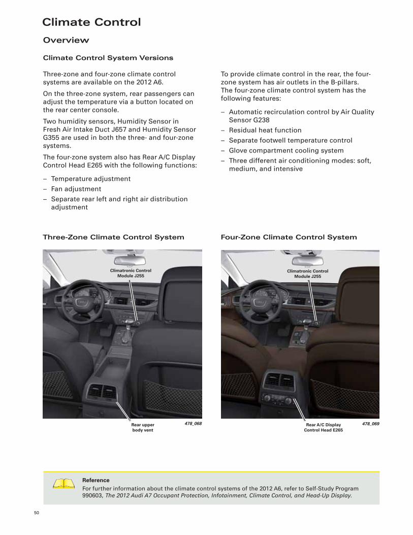
Climate Control System Versions
Three-zone and four-zone climate control systems are available on the 2012 A6.
On the three-zone system, rear passengers can adjust the temperature via a button located on the rear center console.
Two humidity sensors, Humidity Sensor in Fresh Air Intake Duct J657 and Humidity Sensor G355 are used in both the three- and four-zone systems.
The four-zone system also has Rear A/C Display Control Head E265 with the following functions:
– Temperature adjustment– Fan adjustment– Separate rear left and right air distribution
adjustment
Three-Zone Climate Control System
ReferenceFor further information about the climate control systems of the 2012 A6, refer to Self-Study Program 990603, The 2012 Audi A7 Occupant Protection, Infotainment, Climate Control, and Head-Up Display.
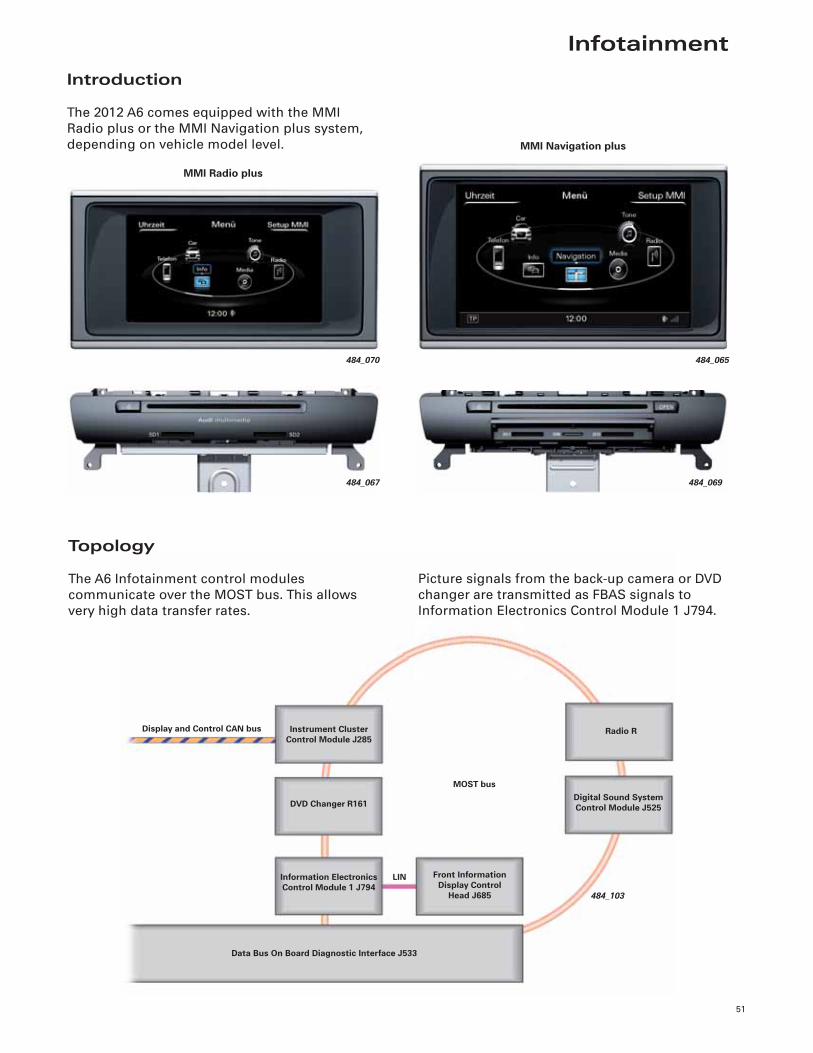
To provide climate control in the rear, the four-zone system has air outlets in the B-pillars. The four-zone climate control system has the following features:
– Automatic recirculation control by Air Quality Sensor G238
– Residual heat function– Separate footwell temperature control– Glove compartment cooling system– Three different air conditioning modes: soft,
medium, and intensive
Four-Zone Climate Control System
478_068
Climatronic Control Module J255
Rear upper body vent
478_069Rear A/C Display Control Head E265
Climatronic Control Module J255
Infotainment
51
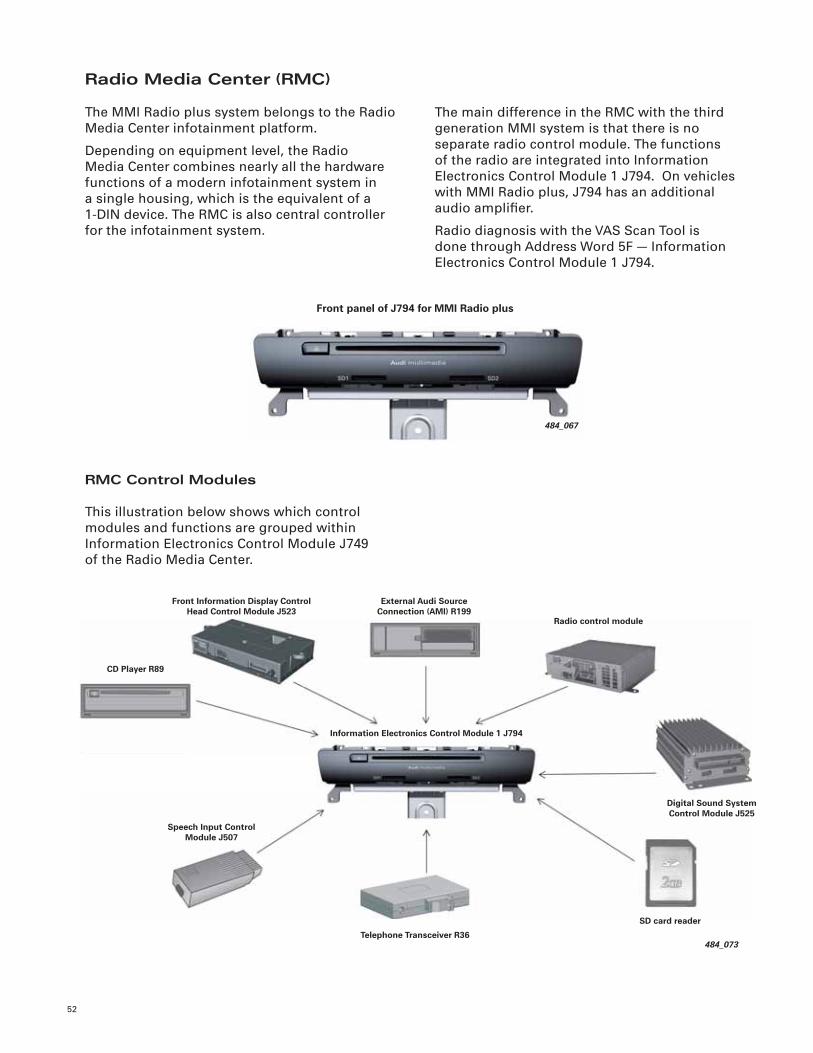
484_103
Radio RDisplay and Control CAN bus
Digital Sound System Control Module J525DVD Changer R161
Instrument Cluster Control Module J285
Front Information Display Control
Head J685
LIN
MOST bus
Information Electronics Control Module 1 J794
Data Bus On Board Diagnostic Interface J533
Introduction
The 2012 A6 comes equipped with the MMI Radio plus or the MMI Navigation plus system, depending on vehicle model level.
484_070
484_067
MMI Radio plus
484_065
484_069
MMI Navigation plus
Topology
The A6 Infotainment control modules communicate over the MOST bus. This allows very high data transfer rates.
Picture signals from the back-up camera or DVD changer are transmitted as FBAS signals to Information Electronics Control Module 1 J794.
52
Radio Media Center (RMC)
The MMI Radio plus system belongs to the Radio Media Center infotainment platform.
Depending on equipment level, the Radio Media Center combines nearly all the hardware functions of a modern infotainment system in a single housing, which is the equivalent of a 1-DIN device. The RMC is also central controller for the infotainment system.
The main difference in the RMC with the third generation MMI system is that there is no separate radio control module. The functions of the radio are integrated into Information Electronics Control Module 1 J794. On vehicles with MMI Radio plus, J794 has an additional audio amplifi er.
Radio diagnosis with the VAS Scan Tool is done through Address Word 5F — Information Electronics Control Module 1 J794.
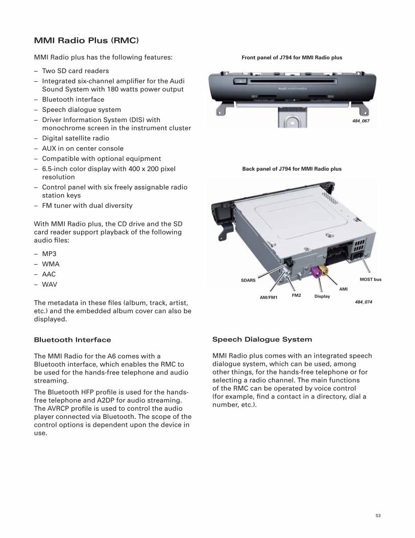
RMC Control Modules
This illustration below shows which control modules and functions are grouped within Information Electronics Control Module J749of the Radio Media Center.
484_067
Front panel of J794 for MMI Radio plus
484_073
Radio control module
CD Player R89
Digital Sound System Control Module J525
Information Electronics Control Module 1 J794
Speech Input Control Module J507
Telephone Transceiver R36
SD card reader
Front Information Display Control Head Control Module J523
External Audi Source Connection (AMI) R199
53
484_067
Front panel of J794 for MMI Radio plus
Speech Dialogue System
MMI Radio plus comes with an integrated speech dialogue system, which can be used, among other things, for the hands-free telephone or for selecting a radio channel. The main functions of the RMC can be operated by voice control (for example, fi nd a contact in a directory, dial a number, etc.).
MMI Radio Plus (RMC)
MMI Radio plus has the following features:
– Two SD card readers– Integrated six-channel amplifi er for the Audi
Sound System with 180 watts power output– Bluetooth interface– Speech dialogue system– Driver Information System (DIS) with
monochrome screen in the instrument cluster– Digital satellite radio– AUX in on center console– Compatible with optional equipment– 6.5-inch color display with 400 x 200 pixel
resolution– Control panel with six freely assignable radio
station keys– FM tuner with dual diversity
With MMI Radio plus, the CD drive and the SD card reader support playback of the following audio fi les:
– MP3– WMA– AAC– WAV
The metadata in these fi les (album, track, artist, etc.) and the embedded album cover can also be displayed.
Bluetooth Interface
The MMI Radio for the A6 comes with a Bluetooth interface, which enables the RMC to be used for the hands-free telephone and audio streaming.
The Bluetooth HFP profi le is used for the hands-free telephone and A2DP for audio streaming. The AVRCP profi le is used to control the audio player connected via Bluetooth. The scope of the control options is dependent upon the device in use.
484_074
MOST bus
AM/FM1
SDARS
FM2 Display
AMI
Back panel of J794 for MMI Radio plus
54
484_069
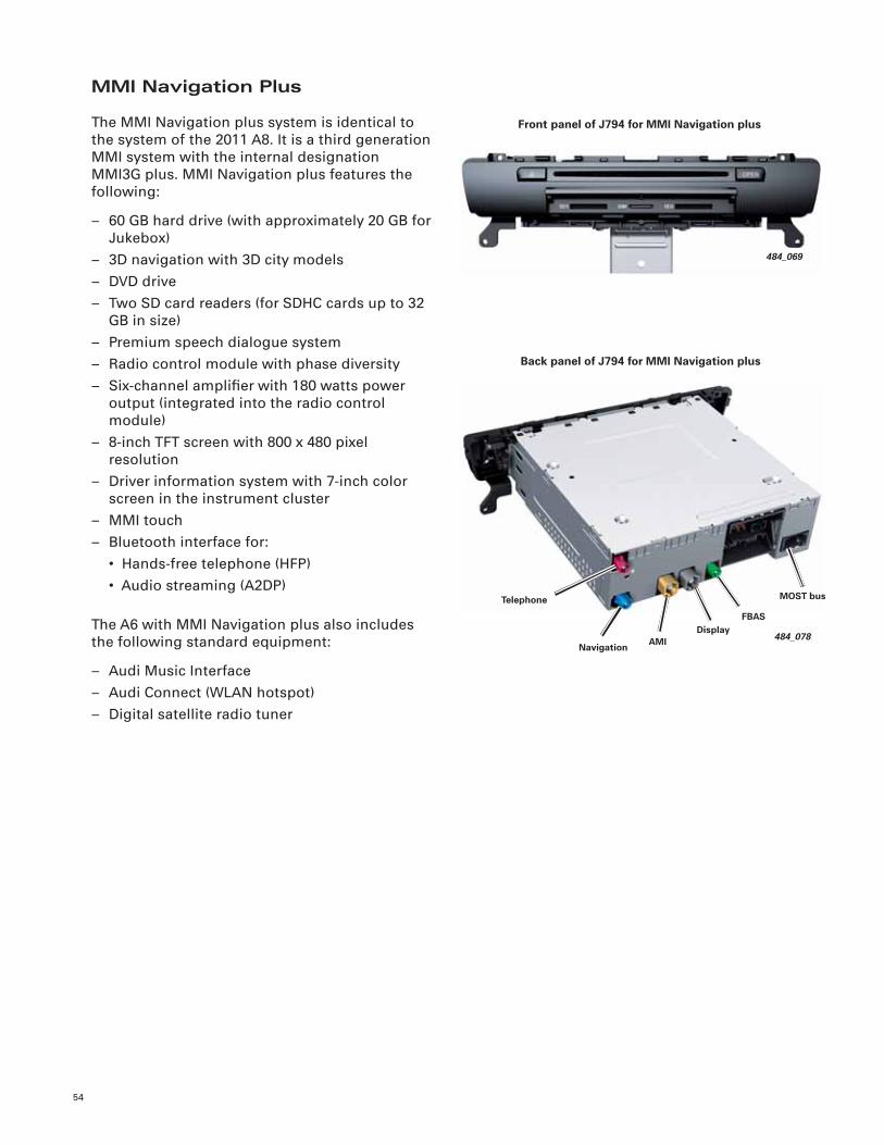
Front panel of J794 for MMI Navigation plus
MMI Navigation Plus
The MMI Navigation plus system is identical to the system of the 2011 A8. It is a third generation MMI system with the internal designation MMI3G plus. MMI Navigation plus features the following:
– 60 GB hard drive (with approximately 20 GB for Jukebox)
– 3D navigation with 3D city models– DVD drive– Two SD card readers (for SDHC cards up to 32
GB in size)– Premium speech dialogue system– Radio control module with phase diversity– Six-channel amplifi er with 180 watts power
output (integrated into the radio control module)
– 8-inch TFT screen with 800 x 480 pixel resolution
– Driver information system with 7-inch color screen in the instrument cluster
– MMI touch– Bluetooth interface for: • Hands-free telephone (HFP) • Audio streaming (A2DP)
The A6 with MMI Navigation plus also includes the following standard equipment:
– Audi Music Interface– Audi Connect (WLAN hotspot)– Digital satellite radio tuner
484_078
MOST bus
Navigation
Telephone
FBASDisplay
AMI
Back panel of J794 for MMI Navigation plus
55
484_079
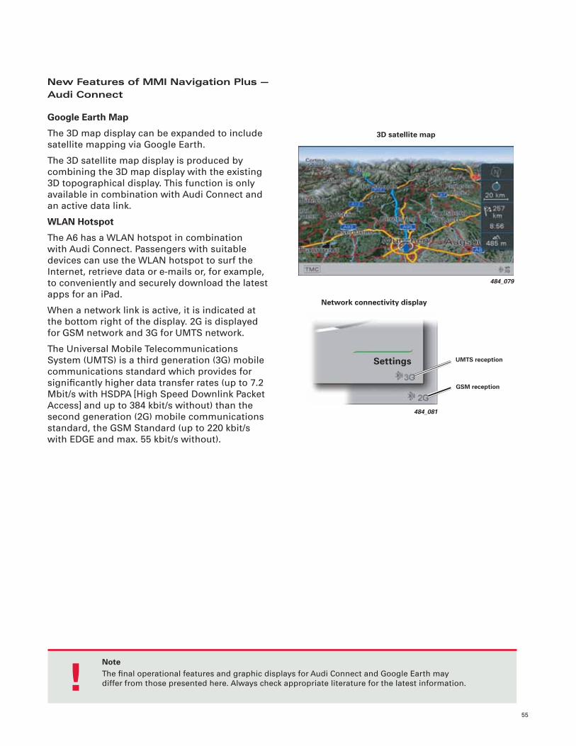
3D satellite map
484_081
UMTS reception
GSM reception
Settings
New Features of MMI Navigation Plus — Audi Connect
Google Earth Map
The 3D map display can be expanded to include satellite mapping via Google Earth.
The 3D satellite map display is produced by combining the 3D map display with the existing 3D topographical display. This function is only available in combination with Audi Connect and an active data link.
WLAN Hotspot
The A6 has a WLAN hotspot in combination with Audi Connect. Passengers with suitable devices can use the WLAN hotspot to surf the Internet, retrieve data or e-mails or, for example, to conveniently and securely download the latest apps for an iPad.
When a network link is active, it is indicated at the bottom right of the display. 2G is displayed for GSM network and 3G for UMTS network.
The Universal Mobile Telecommunications System (UMTS) is a third generation (3G) mobile communications standard which provides for signifi cantly higher data transfer rates (up to 7.2 Mbit/s with HSDPA [High Speed Downlink Packet Access] and up to 384 kbit/s without) than the second generation (2G) mobile communications standard, the GSM Standard (up to 220 kbit/s with EDGE and max. 55 kbit/s without).
Network connectivity display
NoteThe fi nal operational features and graphic displays for Audi Connect and Google Earth maydiffer from those presented here. Always check appropriate literature for the latest information. !
56
484_082
Settings
Criteria
Destination
Navigation
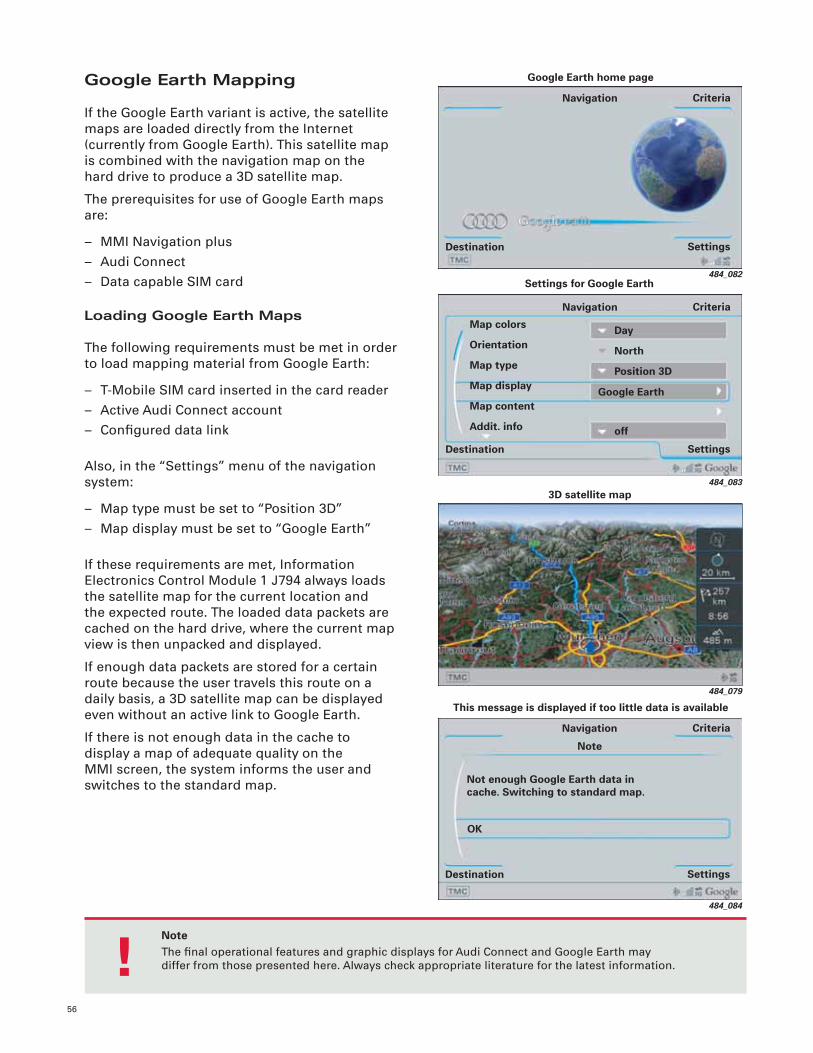
Google Earth home page
484_079
3D satellite map
484_084
This message is displayed if too little data is available
Not enough Google Earth data in cache. Switching to standard map.
Settings
Criteria
Destination
Navigation
OK
Note
Google Earth Mapping
If the Google Earth variant is active, the satellite maps are loaded directly from the Internet (currently from Google Earth). This satellite map is combined with the navigation map on the hard drive to produce a 3D satellite map.
The prerequisites for use of Google Earth maps are:
– MMI Navigation plus– Audi Connect– Data capable SIM card
Loading Google Earth Maps
The following requirements must be met in order to load mapping material from Google Earth:
– T-Mobile SIM card inserted in the card reader– Active Audi Connect account– Confi gured data link
Also, in the “Settings” menu of the navigation system:
– Map type must be set to “Position 3D”– Map display must be set to “Google Earth”
If these requirements are met, Information Electronics Control Module 1 J794 always loads the satellite map for the current location and the expected route. The loaded data packets are cached on the hard drive, where the current map view is then unpacked and displayed.
If enough data packets are stored for a certain route because the user travels this route on a daily basis, a 3D satellite map can be displayed even without an active link to Google Earth.
If there is not enough data in the cache to display a map of adequate quality on the MMI screen, the system informs the user and switches to the standard map.
484_083
Day
North
Position 3D
Settings for Google Earth
Settings
Criteria
Destination
Navigation
Map colors
Orientation
Map type
Map display
Map content
Addit. info
Google Earth
off
NoteThe fi nal operational features and graphic displays for Audi Connect and Google Earth maydiffer from those presented here. Always check appropriate literature for the latest information. !
57
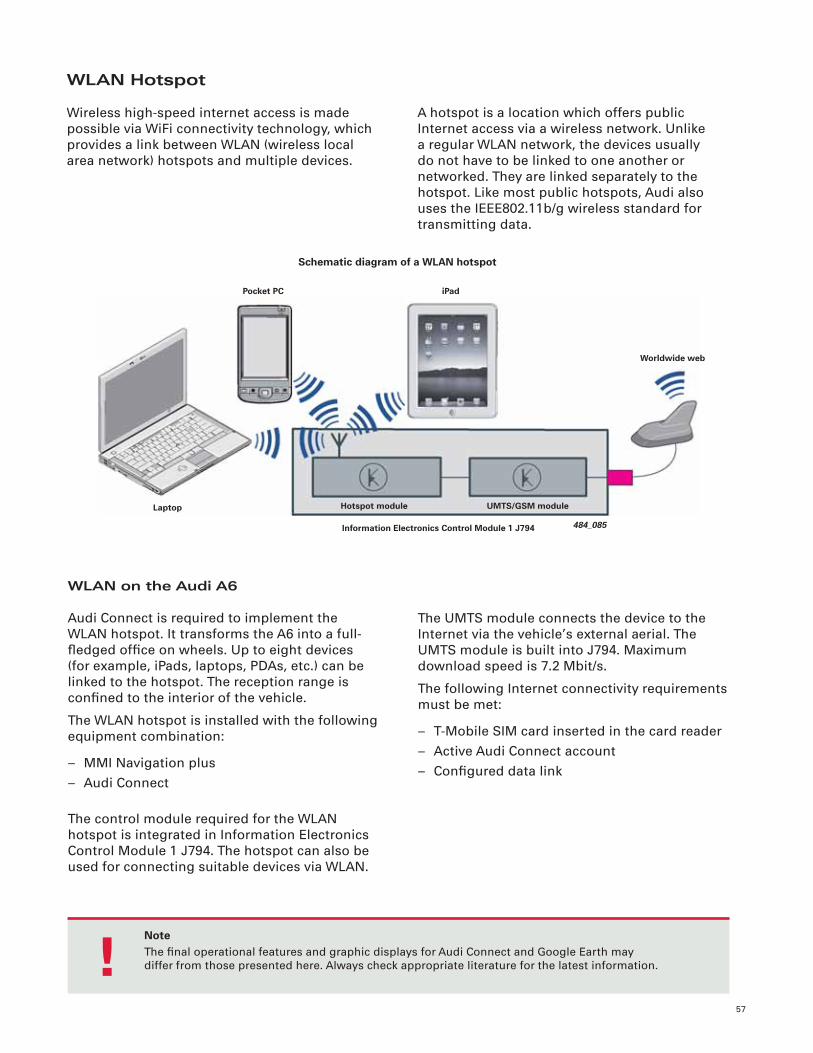
WLAN Hotspot
Wireless high-speed internet access is made possible via WiFi connectivity technology, which provides a link between WLAN (wireless local area network) hotspots and multiple devices.
A hotspot is a location which offers public Internet access via a wireless network. Unlike a regular WLAN network, the devices usually do not have to be linked to one another or networked. They are linked separately to the hotspot. Like most public hotspots, Audi also uses the IEEE802.11b/g wireless standard for transmitting data.
The UMTS module connects the device to the Internet via the vehicle’s external aerial. The UMTS module is built into J794. Maximum download speed is 7.2 Mbit/s.
The following Internet connectivity requirements must be met:
– T-Mobile SIM card inserted in the card reader– Active Audi Connect account– Confi gured data link
WLAN on the Audi A6
Audi Connect is required to implement the WLAN hotspot. It transforms the A6 into a full-fl edged offi ce on wheels. Up to eight devices (for example, iPads, laptops, PDAs, etc.) can be linked to the hotspot. The reception range is confi ned to the interior of the vehicle.
The WLAN hotspot is installed with the following equipment combination:
– MMI Navigation plus– Audi Connect
The control module required for the WLAN hotspot is integrated in Information Electronics Control Module 1 J794. The hotspot can also be used for connecting suitable devices via WLAN.
484_085Information Electronics Control Module 1 J794
Worldwide web
Pocket PC
Laptop
iPad
Hotspot module UMTS/GSM module
Schematic diagram of a WLAN hotspot
NoteThe fi nal operational features and graphic displays for Audi Connect and Google Earth maydiffer from those presented here. Always check appropriate literature for the latest information. !
58
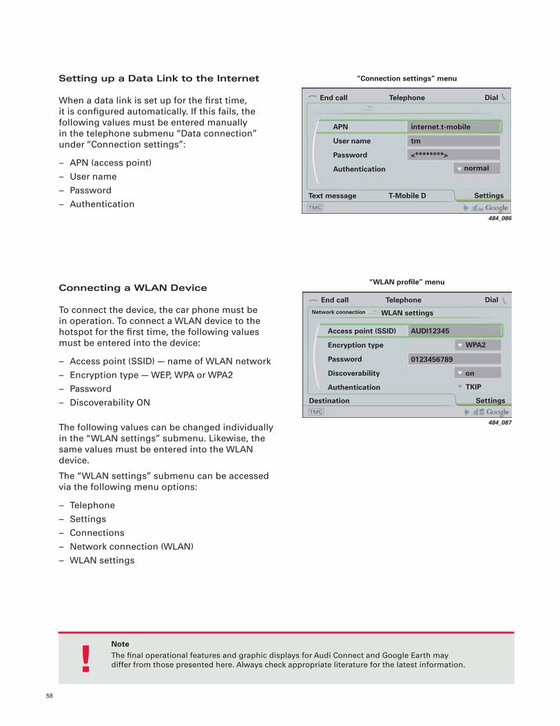
Setting up a Data Link to the Internet
When a data link is set up for the fi rst time, it is confi gured automatically. If this fails, the following values must be entered manually in the telephone submenu “Data connection” under “Connection settings”:
– APN (access point)– User name– Password– Authentication
484_086
internet.t-mobile
tm
<********>
End call
Settings
Dial
Text message
Telephone
APN
User name
Password
Authentication normal
“Connection settings” menu
T-Mobile D
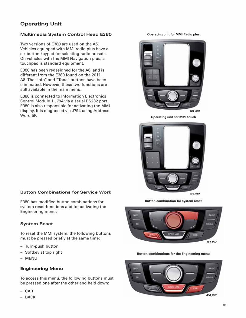
Connecting a WLAN Device
To connect the device, the car phone must be in operation. To connect a WLAN device to the hotspot for the fi rst time, the following values must be entered into the device:
– Access point (SSID) — name of WLAN network– Encryption type — WEP, WPA or WPA2– Password– Discoverability ON
The following values can be changed individually in the “WLAN settings” submenu. Likewise, the same values must be entered into the WLAN device.
The “WLAN settings” submenu can be accessed via the following menu options:
– Telephone– Settings– Connections– Network connection (WLAN)– WLAN settings
484_087
SettingsDestination
Access point (SSID)
Encryption type
Password
Discoverability
Authentication
AUDI12345
WPA2
“WLAN profi le” menu
End call DialTelephoneNetwork connection WLAN settings
TKIP
0123456789
on
NoteThe fi nal operational features and graphic displays for Audi Connect and Google Earth maydiffer from those presented here. Always check appropriate literature for the latest information. !
59
Operating Unit
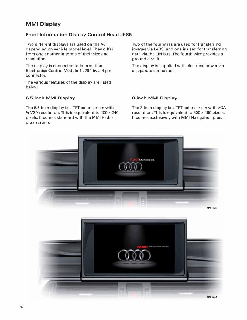
Multimedia System Control Head E380
Two versions of E380 are used on the A6. Vehicles equipped with MMI radio plus have a six button keypad for selecting radio presets. On vehicles with the MMI Navigation plus, a touchpad is standard equipment.
E380 has been redesigned for the A6, and is different from the E380 found on the 2011 A8. The “Info” and “Tone” buttons have been eliminated. However, these two functions are still available in the main menu.
E380 is connected to Information Electronics Control Module 1 J794 via a serial RS232 port. E380 is also responsible for activating the MMI display. It is diagnosed via J794 using Address Word 5F.
484_092
Button combination for system reset
484_093
Button combinations for the Engineering menu
484_089
Operating unit for MMI Radio plus
Button Combinations for Service Work
E380 has modifi ed button combinations for system reset functions and for activating the Engineering menu.
System Reset
To reset the MMI system, the following buttons must be pressed briefl y at the same time:
– Turn-push button– Softkey at top right– MENU
Engineering Menu
To access this menu, the following buttons must be pressed one after the other and held down:
– CAR– BACK
484_089
Operating unit for MMI touch
60
MMI Display
Front Information Display Control Head J685
Two of the four wires are used for transferring images via LVDS, and one is used for transferring data via the LIN bus. The fourth wire provides a ground circuit.
The display is supplied with electrical power via a separate connector.
6.5-inch MMI Display
The 6.5-inch display is a TFT color screen with! VGA resolution. This is equivalent to 400 x 240 pixels. It comes standard with the MMI Radio plus system.
Two different displays are used on the A6, depending on vehicle model level. They differ from one another in terms of their size and resolution.
The display is connected to Information Electronics Control Module 1 J794 by a 4 pin connector.
The various features of the display are listed below.
484_095
484_094
8-inch MMI Display
The 8-inch display is a TFT color screen with VGA resolution. This is equivalent to 800 x 480 pixels. It comes exclusively with MMI Navigation plus.
61
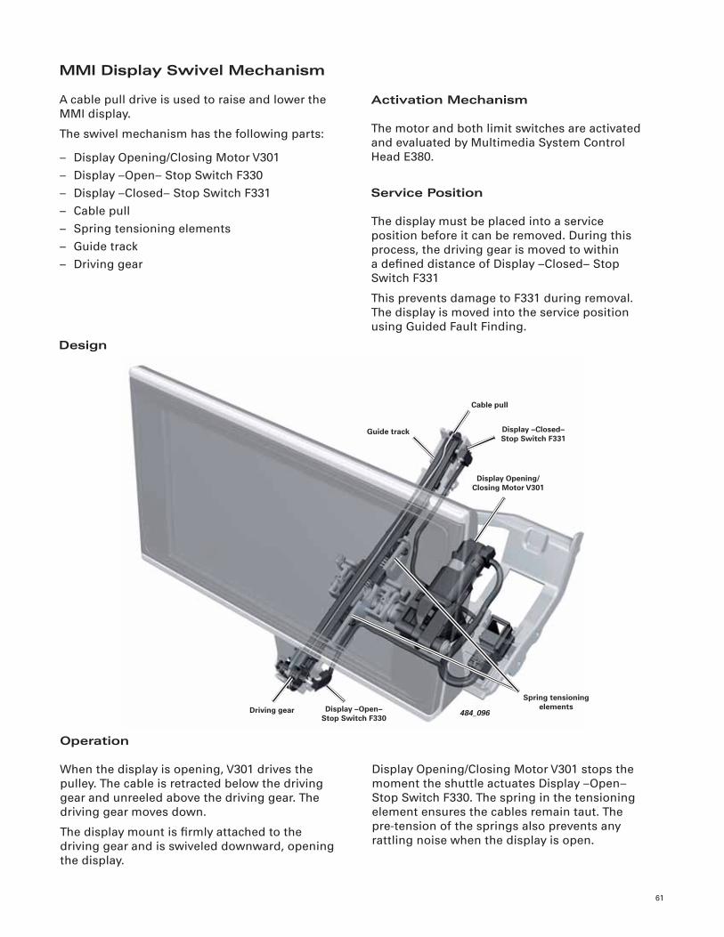
MMI Display Swivel Mechanism
A cable pull drive is used to raise and lower the MMI display.
The swivel mechanism has the following parts:
– Display Opening/Closing Motor V301– Display –Open– Stop Switch F330– Display –Closed– Stop Switch F331– Cable pull– Spring tensioning elements– Guide track– Driving gear
Activation Mechanism
The motor and both limit switches are activated and evaluated by Multimedia System Control Head E380.
Service Position
The display must be placed into a service position before it can be removed. During this process, the driving gear is moved to within a defi ned distance of Display –Closed– Stop Switch F331
This prevents damage to F331 during removal. The display is moved into the service position using Guided Fault Finding.
Operation
When the display is opening, V301 drives the pulley. The cable is retracted below the driving gear and unreeled above the driving gear. The driving gear moves down.
The display mount is fi rmly attached to the driving gear and is swiveled downward, opening the display.
Display Opening/Closing Motor V301 stops the moment the shuttle actuates Display –Open–Stop Switch F330. The spring in the tensioning element ensures the cables remain taut. Thepre-tension of the springs also prevents any rattling noise when the display is open.
Design
484_096
Guide track
Driving gear
Display Opening/Closing Motor V301
Display –Closed– Stop Switch F331
Cable pull
Display –Open– Stop Switch F330
Spring tensioning elements
62
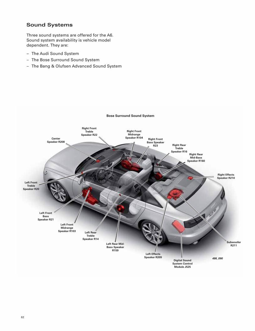
Sound Systems
Three sound systems are offered for the A6. Sound system availability is vehicle model dependent. They are:
– The Audi Sound System– The Bose Surround Sound System– The Bang & Olufsen Advanced Sound System
486_090
Right Rear Mid-Bass
Speaker R160
Right Effects Speaker R210
Right Front Bass Speaker
R23
Center Speaker R208
Right Front Midrange
Speaker R104
Left Front Treble
Speaker R20
Left Front Bass
Speaker R21
Left Rear Treble
Speaker R14
Right Rear Treble
Speaker R16
Left Front Midrange
Speaker R103
Left Rear Mid-Bass Speaker
R159
Digital Sound System Control
Module J525
Subwoofer R211
Left Effects Speaker R209
Right Front Treble
Speaker R22
Bose Surround Sound System
63
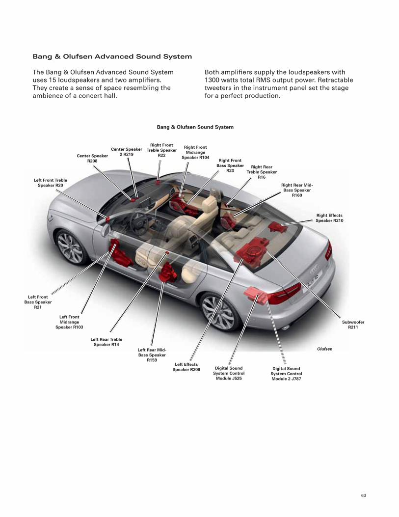
Bang & Olufsen Advanced Sound System
Both amplifi ers supply the loudspeakers with 1300 watts total RMS output power. Retractable tweeters in the instrument panel set the stage for a perfect production.
The Bang & Olufsen Advanced Sound System uses 15 loudspeakers and two amplifi ers. They create a sense of space resembling the ambience of a concert hall.
Olufsen
Right Rear Mid-Bass Speaker
R160
Right Front Midrange
Speaker R104
Center Speaker 2 R219
Left Front Bass Speaker
R21
Center Speaker R208
Left Front Treble Speaker R20
Left Front Midrange
Speaker R103
Left Rear Treble Speaker R14
Right Effects Speaker R210
Right Front Treble Speaker
R22Right Front
Bass Speaker R23
Right Rear Treble Speaker
R16
Left Rear Mid-Bass Speaker
R159Left Effects
Speaker R209 Digital Sound System Control
Module J525
Subwoofer R211
Digital Sound System Control Module 2 J787
Bang & Olufsen Sound System
64
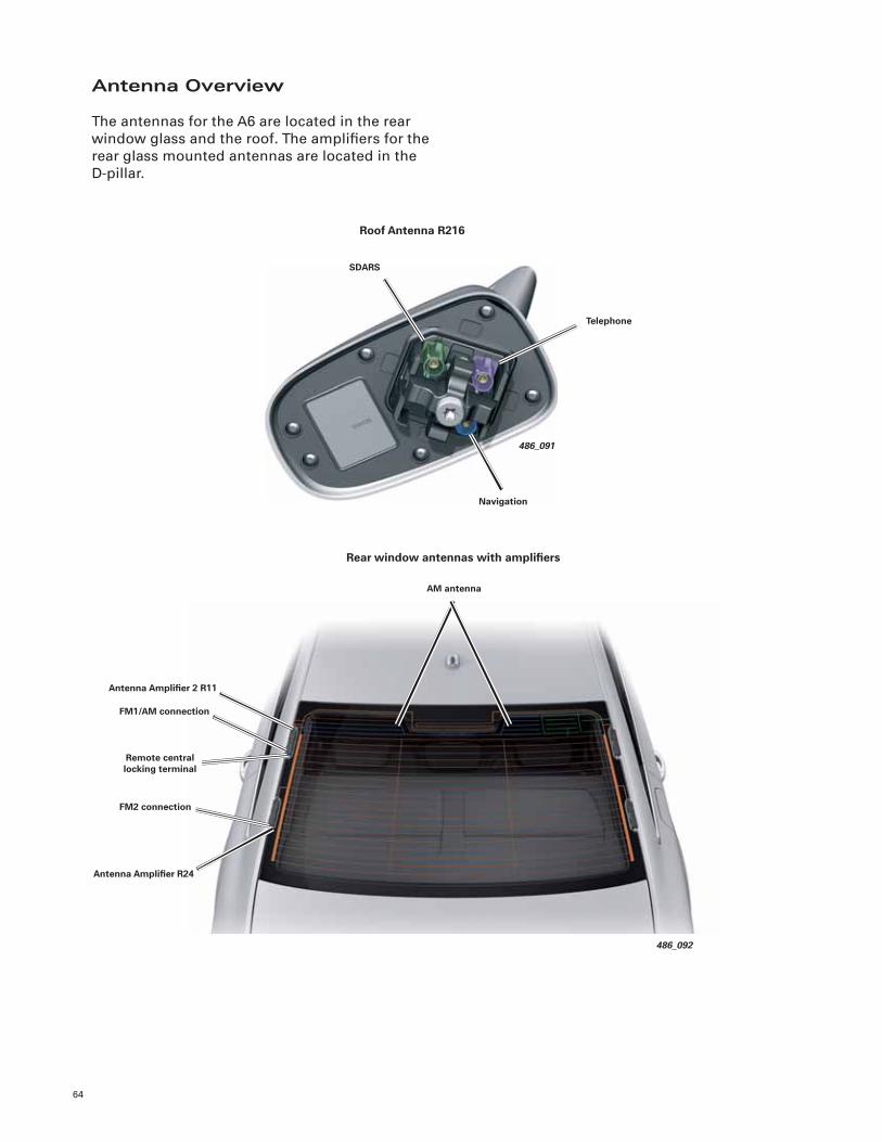
Antenna Overview
The antennas for the A6 are located in the rear window glass and the roof. The amplifi ers for the rear glass mounted antennas are located in the D-pillar.
Telephone
SDARS
Navigation
486_091
Roof Antenna R216
486_092
Antenna Amplifi er 2 R11
Antenna Amplifi er R24
FM2 connection
Rear window antennas with amplifi ers
AM antenna
FM1/AM connection
Remote central locking terminal
Head-Up Display
65
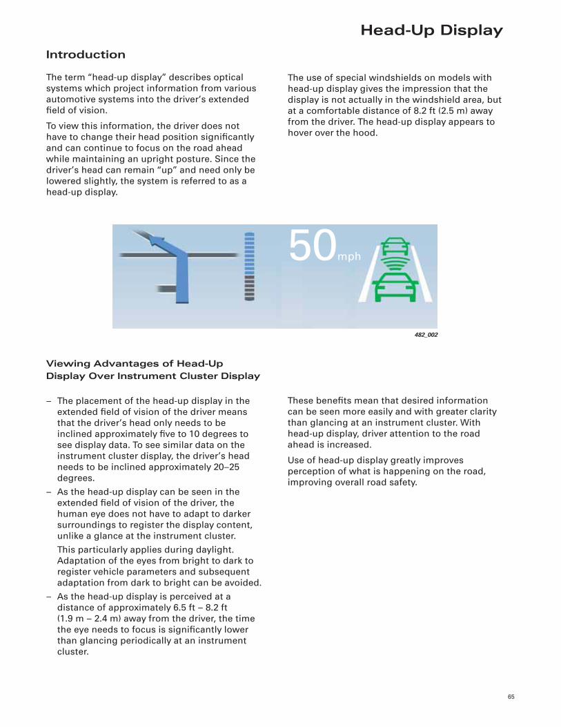
Introduction
The term “head-up display” describes optical systems which project information from various automotive systems into the driver’s extended fi eld of vision.
To view this information, the driver does not have to change their head position signifi cantly and can continue to focus on the road ahead while maintaining an upright posture. Since the driver’s head can remain “up” and need only be lowered slightly, the system is referred to as a head-up display.
The use of special windshields on models with head-up display gives the impression that the display is not actually in the windshield area, but at a comfortable distance of 8.2 ft (2.5 m) away from the driver. The head-up display appears to hover over the hood.
These benefi ts mean that desired information can be seen more easily and with greater clarity than glancing at an instrument cluster. With head-up display, driver attention to the road ahead is increased.
Use of head-up display greatly improves perception of what is happening on the road, improving overall road safety.
Viewing Advantages of Head-Up Display Over Instrument Cluster Display
– The placement of the head-up display in the extended fi eld of vision of the driver means that the driver’s head only needs to be inclined approximately fi ve to 10 degrees to see display data. To see similar data on the instrument cluster display, the driver’s head needs to be inclined approximately 20–25 degrees.
– As the head-up display can be seen in the extended fi eld of vision of the driver, the human eye does not have to adapt to darker surroundings to register the display content, unlike a glance at the instrument cluster.
This particularly applies during daylight. Adaptation of the eyes from bright to dark to register vehicle parameters and subsequent adaptation from dark to bright can be avoided.
– As the head-up display is perceived at a distance of approximately 6.5 ft – 8.2 ft(1.9 m – 2.4 m) away from the driver, the time the eye needs to focus is signifi cantly lower than glancing periodically at an instrument cluster.
482_002
50mph
66
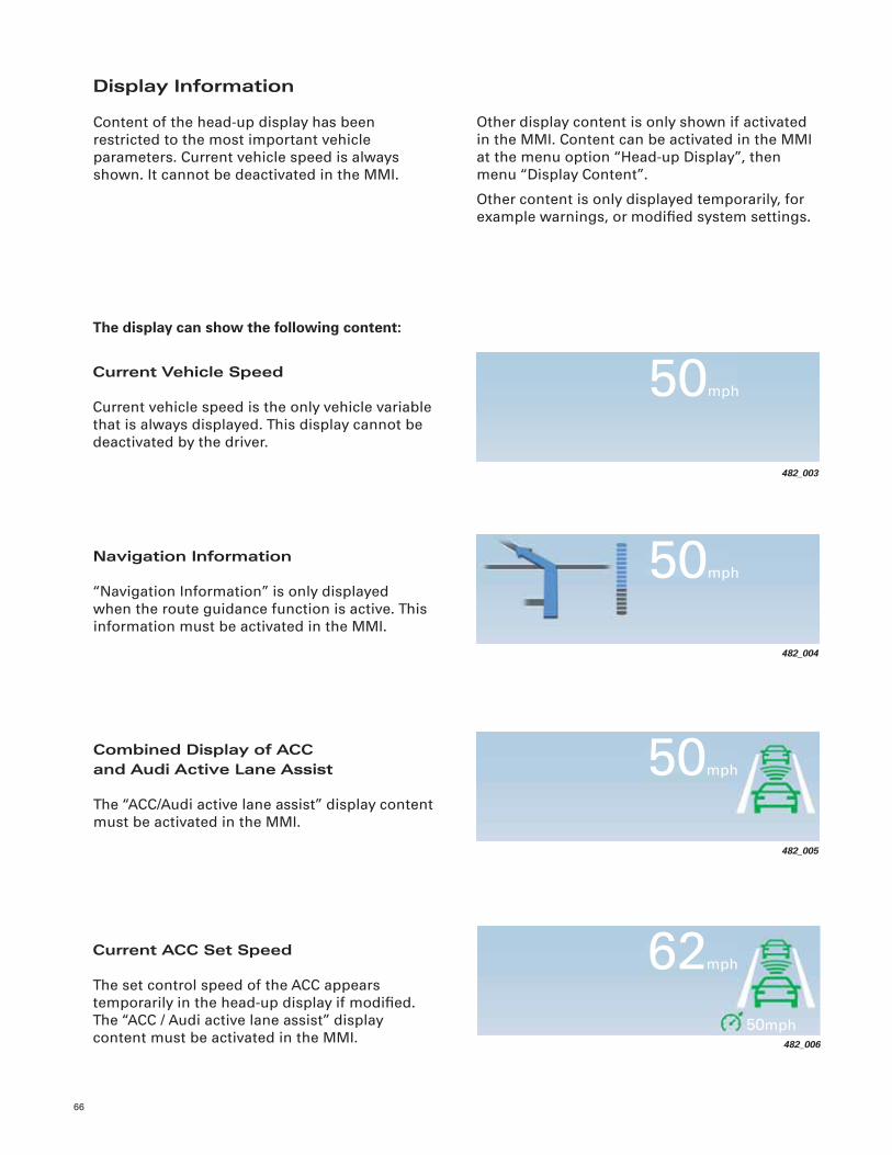
Display Information
Content of the head-up display has been restricted to the most important vehicle parameters. Current vehicle speed is always shown. It cannot be deactivated in the MMI.
Other display content is only shown if activated in the MMI. Content can be activated in the MMI at the menu option “Head-up Display”, then menu “Display Content”.
Other content is only displayed temporarily, for example warnings, or modifi ed system settings.
The display can show the following content:
Current Vehicle Speed
Current vehicle speed is the only vehicle variable that is always displayed. This display cannot be deactivated by the driver.
Current ACC Set Speed
The set control speed of the ACC appears temporarily in the head-up display if modifi ed. The “ACC / Audi active lane assist” display content must be activated in the MMI. 482_006
62mph
50mph
482_003
50mph
482_004
50mph
482_005
50mph
Navigation Information
“Navigation Information” is only displayed when the route guidance function is active. This information must be activated in the MMI.
Combined Display of ACCand Audi Active Lane Assist
The “ACC/Audi active lane assist” display content must be activated in the MMI.
67
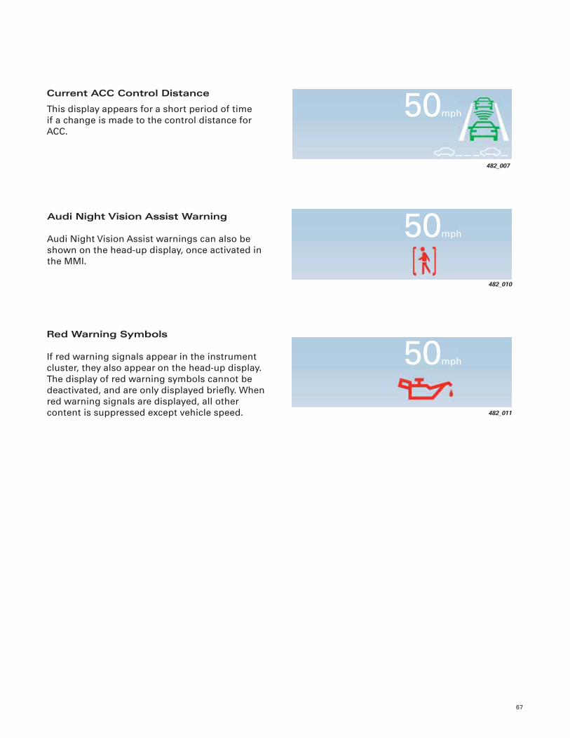
Current ACC Control Distance
This display appears for a short period of time if a change is made to the control distance for ACC.
Audi Night Vision Assist Warning
Audi Night Vision Assist warnings can also be shown on the head-up display, once activated in the MMI.
482_007
50mph
482_010
50mph
482_011
50mph
Red Warning Symbols
If red warning signals appear in the instrument cluster, they also appear on the head-up display. The display of red warning symbols cannot be deactivated, and are only displayed briefl y. When red warning signals are displayed, all other content is suppressed except vehicle speed.
68
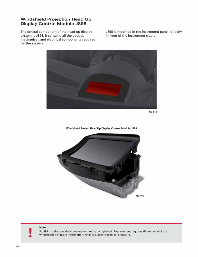
Windshield Projection Head Up Display Control Module J898
The central component of the head-up display system is J898. It contains all the optical, mechanical, and electrical components required for the system.
J898 is mounted in the instrument panel, directly in front of the instrument cluster.
482_012
NoteIf J898 is defective, the complete unit must be replaced. Replacement requires the removal of the windshield. For more information, refer to current technical literature.!
482_013
Windshield Project Head Up Display Control Module J898
69
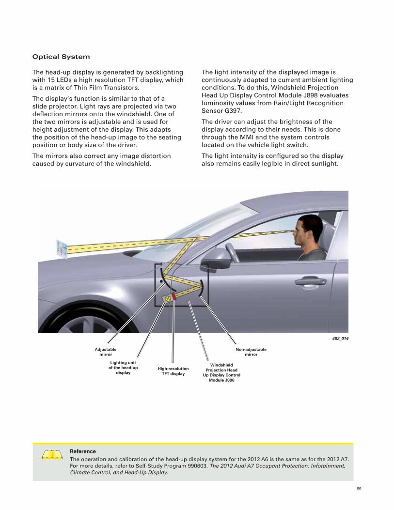
Optical System
The head-up display is generated by backlighting with 15 LEDs a high resolution TFT display, which is a matrix of Thin Film Transistors.
The display’s function is similar to that of a slide projector. Light rays are projected via two defl ection mirrors onto the windshield. One of the two mirrors is adjustable and is used for height adjustment of the display. This adapts the position of the head-up image to the seating position or body size of the driver.
The mirrors also correct any image distortion caused by curvature of the windshield.
The light intensity of the displayed image is continuously adapted to current ambient lighting conditions. To do this, Windshield Projection Head Up Display Control Module J898 evaluates luminosity values from Rain/Light Recognition Sensor G397.
The driver can adjust the brightness of the display according to their needs. This is done through the MMI and the system controls located on the vehicle light switch.
The light intensity is confi gured so the display also remains easily legible in direct sunlight.
482_014
Adjustable mirror
Lighting unit of the head-up
display
Windshield Projection Head
Up Display Control Module J898
Non-adjustable mirror
High-resolution TFT display
ReferenceThe operation and calibration of the head-up display system for the 2012 A6 is the same as for the 2012 A7. For more details, refer to Self-Study Program 990603, The 2012 Audi A7 Occupant Protection, Infotainment, Climate Control, and Head-Up Display.
70
482_017
“terminal 30”
“terminal 31”
Display and Control CANWindshield Projection Head Up Display Control Module J898
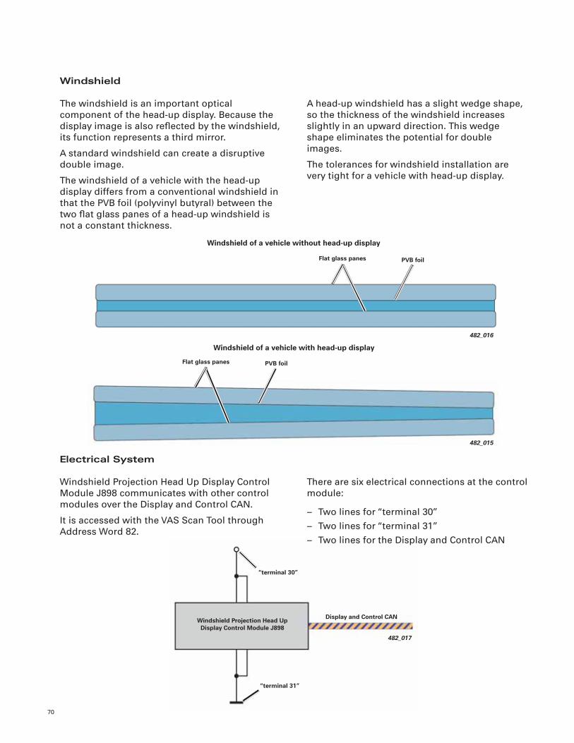
Windshield
The windshield is an important optical component of the head-up display. Because the display image is also refl ected by the windshield, its function represents a third mirror.
A standard windshield can create a disruptive double image.
The windshield of a vehicle with the head-up display differs from a conventional windshield in that the PVB foil (polyvinyl butyral) between the two fl at glass panes of a head-up windshield is not a constant thickness.
A head-up windshield has a slight wedge shape, so the thickness of the windshield increases slightly in an upward direction. This wedge shape eliminates the potential for double images.
The tolerances for windshield installation are very tight for a vehicle with head-up display.
There are six electrical connections at the control module:
– Two lines for “terminal 30”– Two lines for “terminal 31”– Two lines for the Display and Control CAN
Electrical System
Windshield Projection Head Up Display Control Module J898 communicates with other control modules over the Display and Control CAN.
It is accessed with the VAS Scan Tool through Address Word 82.
482_016
Windshield of a vehicle without head-up display
PVB foilFlat glass panes
482_015
PVB foilFlat glass panes
Windshield of a vehicle with head-up display

Notes
71
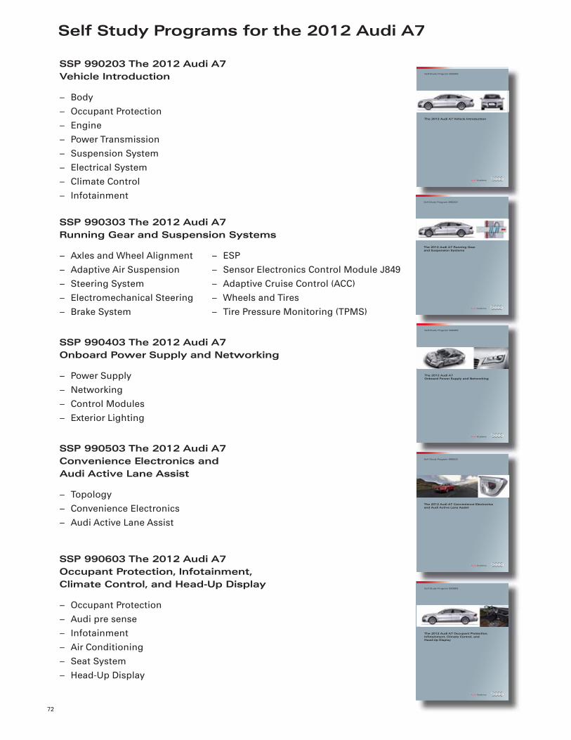
Self Study Programs for the 2012 Audi A7
72
The 2012 Audi A7 Vehicle Introduction
Self-Study Program 990203
The 2012 Audi A7 Running Gear and Suspension Systems
Self-Study Program 990303
The 2012 Audi A7Onboard Power Supply and Networking
Self-Study Program 990403
The 2012 Audi A7 Convenience Electronicsand Audi Active Lane Assist
Self-Study Program 990503
SSP 990203 The 2012 Audi A7Vehicle Introduction
– Body– Occupant Protection– Engine– Power Transmission– Suspension System– Electrical System– Climate Control– Infotainment
SSP 990303 The 2012 Audi A7Running Gear and Suspension Systems
– Axles and Wheel Alignment– Adaptive Air Suspension– Steering System– Electromechanical Steering– Brake System
SSP 990403 The 2012 Audi A7Onboard Power Supply and Networking
– Power Supply– Networking– Control Modules– Exterior Lighting
SSP 990503 The 2012 Audi A7Convenience Electronics andAudi Active Lane Assist
– Topology– Convenience Electronics– Audi Active Lane Assist
SSP 990603 The 2012 Audi A7Occupant Protection, Infotainment,Climate Control, and Head-Up Display
– Occupant Protection– Audi pre sense– Infotainment– Air Conditioning– Seat System– Head-Up Display
The 2012 Audi A7 Occupant Protection, Infotainment, Climate Control, andHead-Up Display
Self-Study Program 990603
– ESP– Sensor Electronics Control Module J849– Adaptive Cruise Control (ACC)– Wheels and Tires– Tire Pressure Monitoring (TPMS)

Knowledge Assessment
73
An on-line Knowledge Assessment (exam) is available for this Self-Study Program.
The Knowledge Assessment is required for Certifi cation.
You can fi nd this Knowledge Assessment at:
www.accessaudi.com
From the accessaudi.com Homepage: – Click on the “ACADEMY” tab – Click on the “Academy Site” link – Click on the “CRC/Certifi cation” link – Click on Course Catalog and select “990613 — The 2012 Audi A6 Vehicle Introduction”
For assistance please call:
Audi Academy
Certifi cation Resource Center (CRC)
1-877-283-4562
(8:00 a.m. to 8:00 p.m. EST)
Or you may send an email to:
Thank you for reading this Self-Study Program and taking the assessment.

Notes
74

99
06
13
All rights reserved.Technical specifi cations subject to change without notice.
Audi of America, LLC2200 Ferdinand Porsche DriveHerndon, VA 20171