bgp/mpls ip vpns - archive.nanog.org · bgp-mpls vpns goal: solve the scaling issues. support...
TRANSCRIPT

Disclaimer
The views presented are of the author and do not necessarily represent Juniper Networks.
Topics
1. VPN basic concepts2. Hierarchical and recursive
applications
Part 1 – Basic concepts
IntroductionHow it worksScalabilityConnectivity models
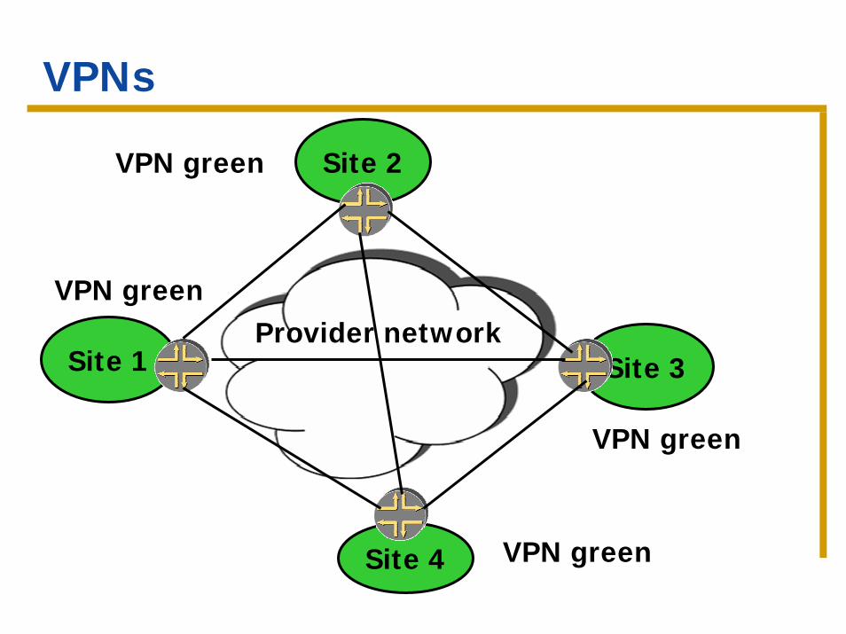
VPNs
Virtual Private Networks – provide a private network over a shared infrastructure.
Interconnect geographically separate sites, with the same privacy and guarantees as a private network.
VPNs
Site 1
Site 2
Site 3
VPN green
VPN green
VPN green
Site 4 VPN green
Provider network
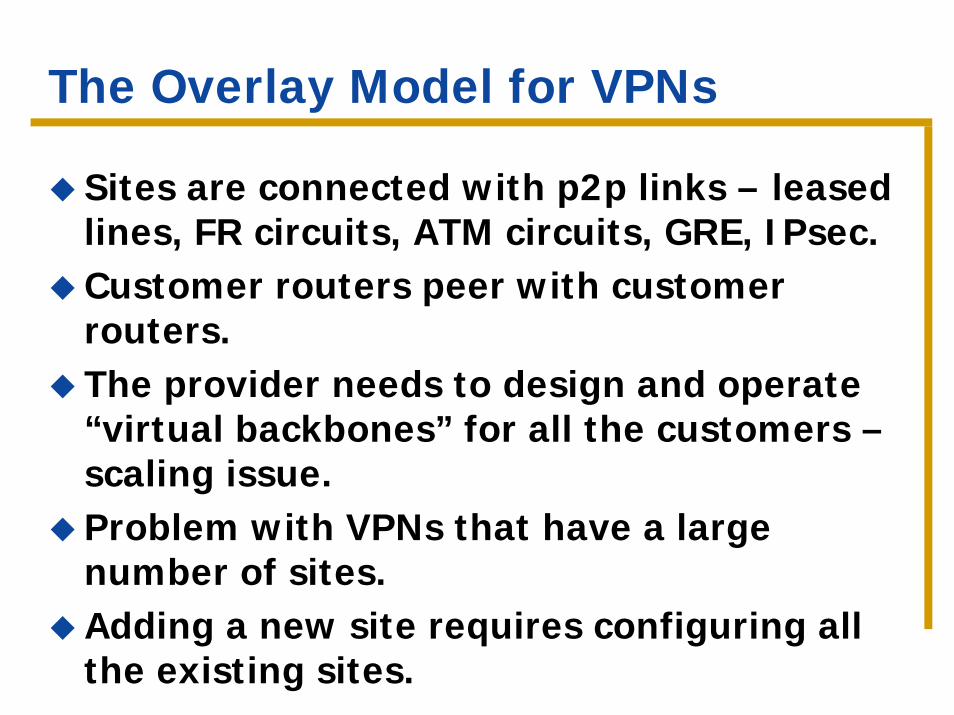
The Overlay Model for VPNs
Sites are connected with p2p links – leased lines, FR circuits, ATM circuits, GRE, IPsec.Customer routers peer with customer routers.The provider needs to design and operate “virtual backbones” for all the customers –scaling issue.Problem with VPNs that have a large number of sites.Adding a new site requires configuring all the existing sites.
BGP-MPLS VPNs
Goal: solve the scaling issues. Support thousands of VPNs, support VPNs with hundreds of sites per VPN, support overlapping address space.
Peer model – customer routers peer with provider routers.
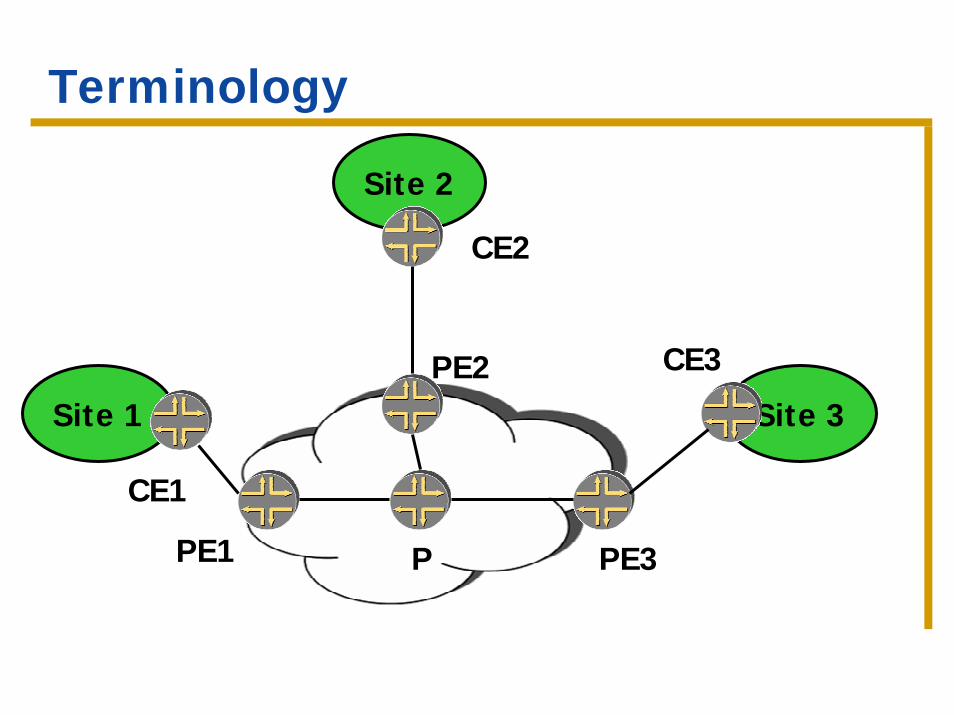
Terminology
Site 2
Site 1 Site 3
CE1
CE2
CE3PE2
PE1 PE3P
Properties of the model
CE router peers with a PE router, but not with other CE routers.
Adding/deleting a new site requires configuring the PE router connected to the site.
A PE router only needs to maintain routes for the VPNs whose sites are directly connected.
Goals
Achieve intersite connectivity
Privacy – don’t allow traffic from one VPN to be seen in another VPN
Independent addressing – private addresses in each VPN.
Part 1 – Basic concepts
IntroductionHow it worksScalabilityConnectivity models
BGP-MPLS VPNs - areas
Separation of forwarding
Distribution of routing information
New address type
Forwarding with MPLS
Operation – separation of forwarding
Goal: control connectivity and ensure privacy by segregating the forwarding information.
PE router connected to CEs from several VPNs.
With a single forwarding table, it is possible to forward packets from one VPN to another.
Multiple forwarding tables
Multiple forwarding tables – each table associated with a site.Packets from the customer are identified based on the incoming port, which identifies the forwarding table.Contents: routes received from the CE, and routes received from remote PEs with constrained routing.
Called VPN routing and forwarding table – VRF.
Operation – Constrained distribution of routing information
The idea: 1. CE advertises routes to the local PE via
some routing protocol.2. The local PE marks these routes with a
particular extended community (route target) and advertises them in BGP.
3. The routes are distributed to all remote PE by BGP.
4. Remote PE receives BGP routes, filters them based on the community and advertises them to the CE.
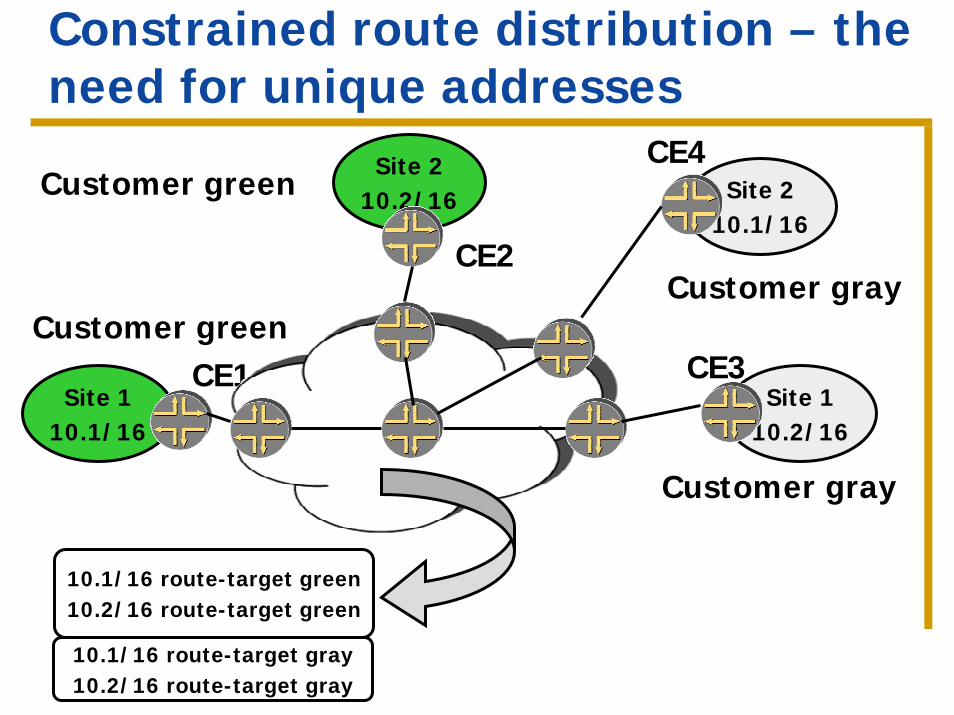
Constrained route distribution – the need for unique addresses
Site 210.2/16
Site 110.1/16
Customer green
Customer green
CE1
CE2
10.1/16 route-target green10.2/16 route-target green
Site 110.2/16
Customer gray
CE3
Site 210.1/16
Customer gray
CE4
10.1/16 route-target gray10.2/16 route-target gray
The model so far (1)
The P routers carry all VPN routes, so the addresses used in the VPNs need to be unique in the provider’s network.
Operation: overlapping address space and VPN-IP addresses
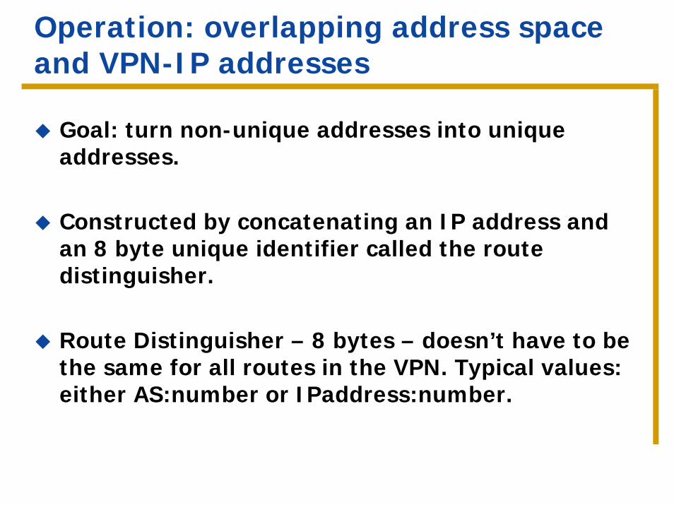
Goal: turn non-unique addresses into unique addresses.
Constructed by concatenating an IP address and an 8 byte unique identifier called the route distinguisher.
Route Distinguisher – 8 bytes – doesn’t have to be the same for all routes in the VPN. Typical values: either AS:number or IPaddress:number.
VPN-IP addresses (cont)
Advertised in a special address family by BGP (MP-BGP)Used only in the provider’s network.Used only in the control plane.The translation from IP addresses to VPN-IP addresses happens on the PE.Not used for route filtering (we use communities for that).
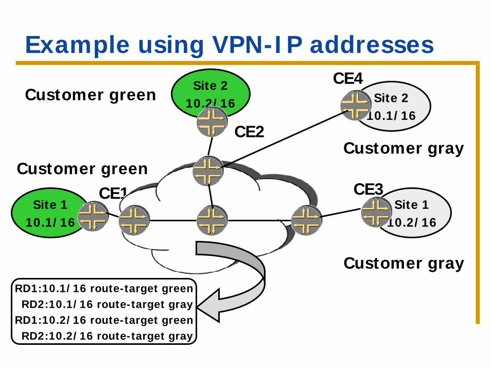
Example using VPN-IP addressesSite 2
10.2/16
Site 110.1/16
Customer greenCE1
CE2
Customer green
Site 110.2/16
Customer gray
CE3
Site 210.1/16
Customer gray
CE4
RD1:10.1/16 route-target greenRD2:10.1/16 route-target gray
RD1:10.2/16 route-target greenRD2:10.2/16 route-target gray
The model so far (2)
Can use overlapping address space.
How to forward based on VPN-IP addresses?
The P routers still carry all the VPN routes.
Why MPLS?
VPN-IP addresses are used by the routing protocols, but do not appear in headers of IP packets.
Need a way to forward traffic along routes to VPN-IP addresses. MPLS decouples forwarding from the destination information.
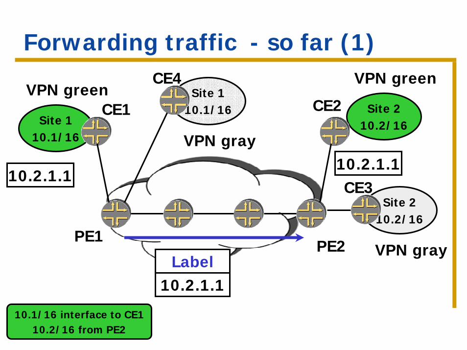
Forwarding traffic - so far (1)
Site 110.1/16
VPN greenCE1 Site 2
10.2/16
VPN green
CE2
10.2.1.1
10.2.1.1Label
Site 110.1/16
VPN gray
CE4
Site 210.2/16
VPN gray
CE3
PE1PE2
10.2.1.1
10.1/16 interface to CE110.2/16 from PE2
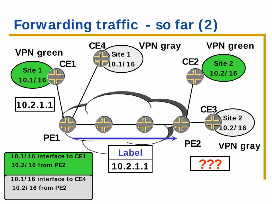
Forwarding traffic - so far (2)
Site 110.1/16
VPN greenCE1 Site 2
10.2/16
VPN green
CE2
10.2.1.1
Site 110.1/16
VPN grayCE4
Site 210.2/16
VPN gray
CE3
PE1PE2
10.1/16 interface to CE110.2/16 from PE2
10.1/16 interface to CE410.2/16 from PE2
???10.2.1.1Label
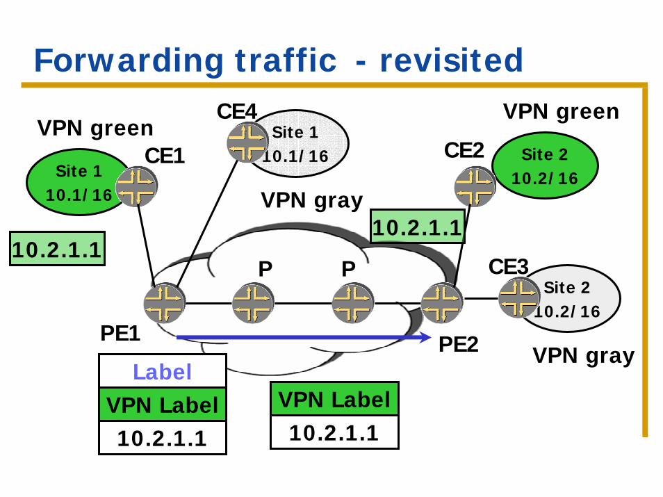
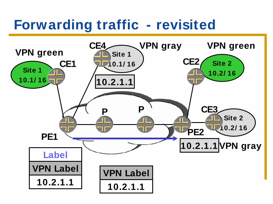
VPN labels
The idea: Use a label to identify the next-hop at the remote PE. Also called VPN label.The label is distributed by BGP, along with the VPN-IP address.Traffic will carry two labels, the VPN label and the LSP label.The remote PE makes the forwarding decision based on the VPN label.
Forwarding traffic - revisited
Site 110.1/16
VPN greenCE1 Site 2
10.2/16
VPN green
CE2
10.2.1.1
Site 110.1/16
VPN gray
CE4
Site 210.2/16
VPN gray
CE3
VPN LabelLabel
10.2.1.1
P P
PE1 PE2
10.2.1.1
VPN Label10.2.1.1
Forwarding traffic - revisited
Site 110.1/16
VPN greenCE1 Site 2
10.2/16
CE2
VPN greenSite 1
10.1/16
VPN grayCE4
Site 210.2/16
VPN gray
CE3
10.2.1.1
VPN LabelLabel
10.2.1.1
10.2.1.1PE1
P P
PE2
VPN Label10.2.1.1
The VPN model - summary
P routers don’t need to maintain VPN routes at all. Only need to maintain routes to other P and PE routers. PE routers maintain VPN routes, but only for VPNs that have sites attached to them.VPNs can have overlapping address spaces.
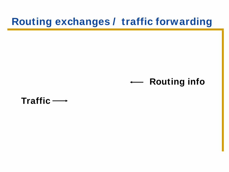
Routing exchanges / traffic forwarding
Routing info
Traffic
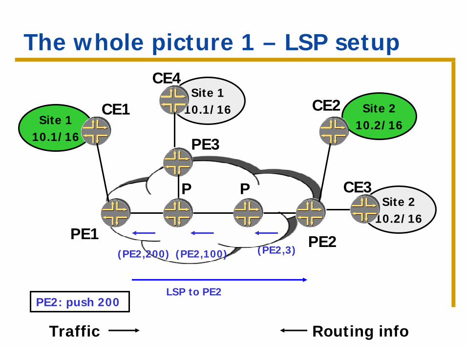
The whole picture 1 – LSP setup
Site 110.1/16
CE1 Site 210.2/16
CE2Site 1
10.1/16
CE4
Site 210.2/16
CE3P P
PE1 PE2
PE3
(PE2,200) (PE2,100) (PE2,3)
LSP to PE2PE2: push 200
Traffic Routing info
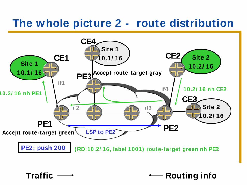
The whole picture 2 - route distribution
Site 110.1/16
CE1 Site 210.2/16
CE2Site 1
10.1/16
CE4
Site 210.2/16
CE3
PE1 PE2
PE3
10.2/16 nh PE110.2/16 nh CE2
LSP to PE2
Accept route-target gray
Accept route-target green
if2
if1
if3
if4
PE2: push 200 (RD:10.2/16, label 1001) route-target green nh PE2
Traffic Routing info
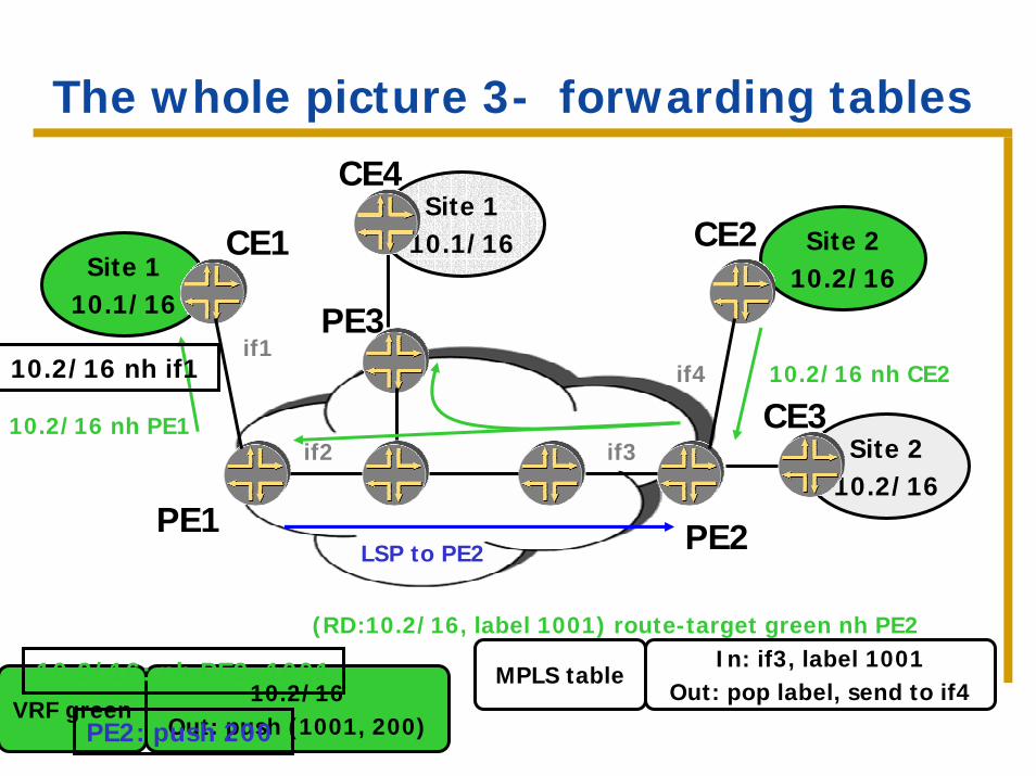
The whole picture 3- forwarding tables
Site 110.1/16
CE1 Site 210.2/16
CE2
PE1 PE2
10.2/16 nh PE1
10.2/16 nh CE2
LSP to PE2
Site 210.2/16
CE3
Site 110.1/16
CE4
PE3
if2
if1
if3
if410.2/16 nh if1
(RD:10.2/16, label 1001) route-target green nh PE2
10.2/16Out: push (1001, 200)
VRF green
10.2/16: nh PE2, 1001
PE2: push 200
In: if3, label 1001Out: pop label, send to if4
MPLS table
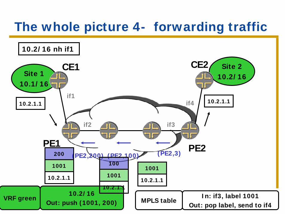
The whole picture 4- forwarding traffic
Site 110.1/16
CE1 Site 210.2/16
CE2
PE1 PE2
10.2/16Out: push (1001, 200)
VRF green
if2
if1
if3
if4
In: if3, label 1001Out: pop label, send to if4
MPLS table
10.2/16 nh if1
(PE2,200) (PE2,100) (PE2,3)
10.2.1.1
10.2.1.1
1001
200
10.2.1.1
1001
100
10.2.1.1
1001
10.2.1.1
The whole picture - summary
Full mesh of BGP between all PEs.
MPLS connectivity between all PEs.
BGP advertises a label along with the VPN-IP address. This determines the next-hop to use when receiving traffic.
Concepts
1. Use MPLS to forward traffic across nodes that don’t have routing information for the packet’s final destination.
2. Use a label to mark the traffic. Use this marking to determine the next-hop.
3. The address of the next-hop in the BGP advertisement provides coupling between the VPN routes and the internal routing to the remote PE.
Part 1 – Basic concepts
IntroductionHow it worksScalabilityConnectivity models
Scaling properties
Only one routing peering (CE-PE), regardless of the number of sites in the VPN.
The customer doesn’t need routing skills. A customer doesn’t need to operate its own backbone.
Adding a new site requires configuration of one PE regardless of the number of sites (constant # of changes required to add a new site)
Scaling properties
PE has to maintain routes only for the VPNs to which it is connected.
P routers don’t have to maintain VPN routes at all.
Scaling properties
Can use overlapping address spaces –efficient use of private IP addresses.
Route distinguishers are structured so that each service provider can manage its own number space.
Part 1 – Basic concepts
IntroductionHow it worksScalabilityConnectivity models
Intersite connectivity
Achieved through constrained distribution of routing information.Done by the PE:
No expertise required from the customer.No configuration necessary on the customer box.
Extended communities allow definition of very flexible policies.
Intersite connectivity models
Connectivity modelsAny-to-anyHub and spoke
Any other combination also possible.
Hub and spoke
The goal: make all the traffic originated at spoke sites go through one hub site (e.g. for implementing a firewall)
The hub site has knowledge of all destinations in the spoke sites.
Hub and spoke
Spoke sites export routes to the hub site using the “spoke” route target. The hub site re-exports these routes with a “hub” route target.
Spoke sites only import routes with community “hub”.Traffic will flow from the spoke sites through the hub.
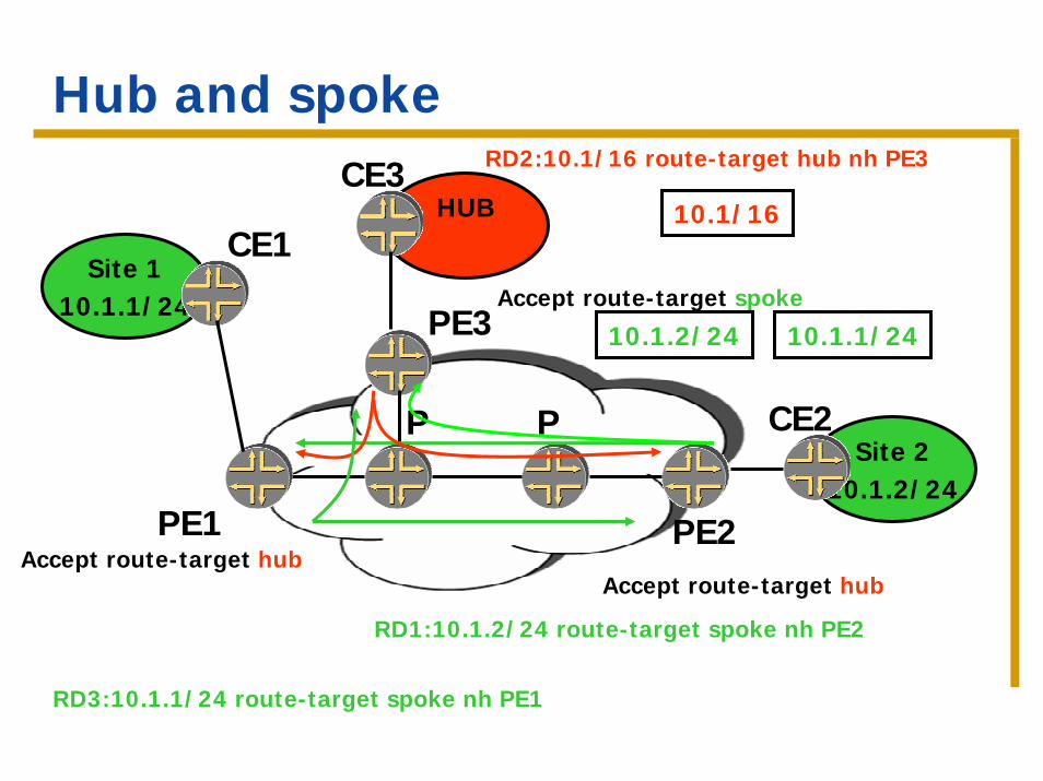
Hub and spoke
Site 110.1.1/24
CE1HUB
CE3
Site 210.1.2/24
CE2P P
PE1 PE2
PE3
Accept route-target hub
Accept route-target spoke
Accept route-target hub
10.1.2/24
RD2:10.1/16 route-target hub nh PE3
10.1.1/24
10.1/16
RD1:10.1.2/24 route-target spoke nh PE2
RD3:10.1.1/24 route-target spoke nh PE1
Part 2 – Hierarchical and recursive applications
IntroductionISP as a VPN customerVPN service provider as a VPN customerVPN services across AS boundaries
Introduction
VPN customer is himself a service provider: ISP or VPN service provider.Carriers carrier – all customer sites are in the same AS.Multi-AS operations – the customer sites have different AS numbers (VPN service spans two providers)
Introduction - terminology
External routes – learned from peering points or from customers. Carried in BGP.
Internal routes – include the provider’s internal links (including BGP next-hops) and loopbacks. Carried in the IGP.
Concepts we saw previously
Use MPLS to forward traffic across nodes that don’t have routing information for the packet’s final destination.
Use a label to mark traffic. Use this marking to pick the correct next-hop.
The BGP next-hop is the glue between external routes and internal routes.
Part 2 – Hierarchical and recursive applications
IntroductionISP as a VPN customerVPN service provider as a VPN customerVPN services across AS boundaries
ISP as a VPN customer
Goal – interconnect geographically separate sites of the ISP (e.g. POPs).
Also known as “Carriers carrier”, section 9 of 2547bis.
Two scenarios:No MPLS within the sites – within a site, forward based on IP.With MPLS within the sites – can use MPLS to forward within a site.
ISP as a VPN customer – step (1)
The problem:Requires the PE routers to carry a full set of internet routes as VPN-customer routes… for each such customer…Requires the VPN provider to distribute the routes for each of the customers throughout the network (large amount of routing information).
The solution: let the customer be responsible for the external routes.
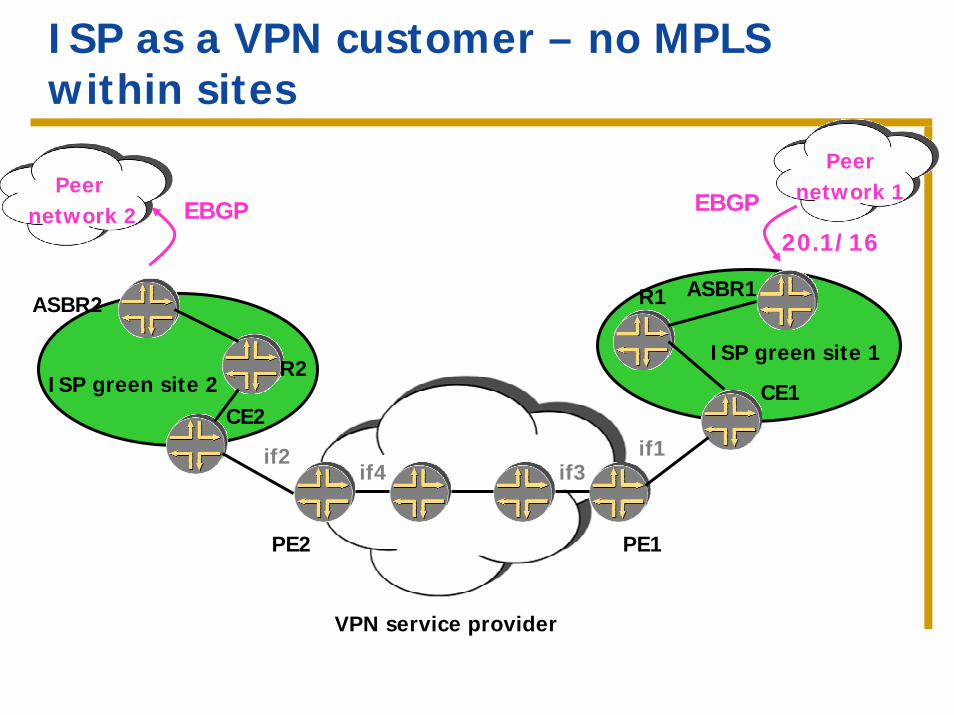
ISP as a VPN customer – no MPLS within sites
ASBR2
R2
CE2ISP green site 2
ASBR1R1
CE1
ISP green site 1
Peernetwork 1 Peer
network 2 EBGP EBGP
20.1/16
PE2 PE1
VPN service provider
if2if3if4
if1
ISP as a VPN customer – step (1)
External routes are exchanged via BGP between the two geographically dispersed sites.
Need to be able to establish BGP sessions across the VPN provider => must have routes to the routers in the other POP.
Advertise the internal routes as the VPN customer routes.
ISP as a VPN customer – scenario 1 – no MPLS within the customer sites
No MPLS in the customer sites.
Goal – the provider doesn’t want to carry the customer’s external routes.
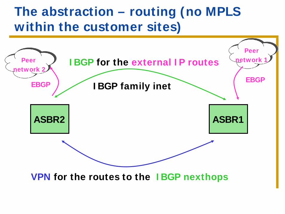
The abstraction – routing (no MPLS within the customer sites)
Peernetwork 1
EBGP
IBGP for the external IP routesPeer network 2
EBGP IBGP family inet
ASBR2 ASBR1
VPN for the routes to the IBGP nexthops

Routing exchanges / traffic forwarding
Site 2 Site 1
Routing info
Traffic
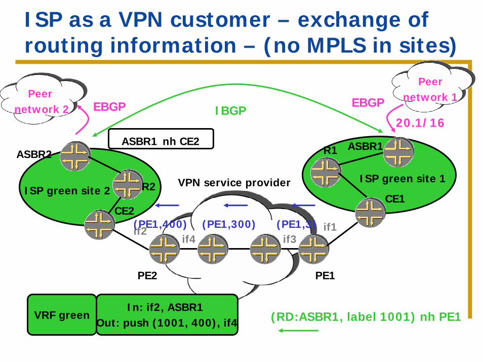
ISP as a VPN customer – exchange of routing information – (no MPLS in sites)
PE2
ASBR2
R2
CE2
PE1
ISP green site 2
ASBR1R1
CE1
ISP green site 1
Peernetwork 1 Peer
network 2 EBGP EBGP
20.1/16
VPN service provider
if2 if1
(RD:ASBR1, label 1001) nh PE1
(PE1,400) (PE1,300) (PE1,3)
In: if2, ASBR1 Out: push (1001, 400), if4
VRF green
if3if4
IBGP
ASBR1 nh CE2
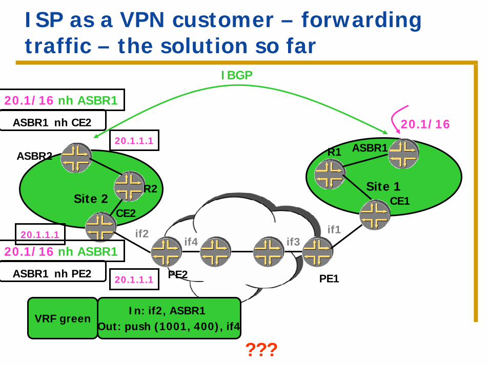
ISP as a VPN customer – forwarding traffic – the solution so far
Site 1
PE2
Site 2
ASBR2
R2
CE2
PE1
ASBR1R1
CE1
IBGP
20.1/16
if2 if1
In: if2, ASBR1 Out: push (1001, 400), if4
VRF green
if3if4
20.1/16 nh ASBR1
ASBR1 nh CE2
20.1.1.1
20.1.1.1
???
20.1/16 nh ASBR1
ASBR1 nh PE2
20.1.1.1
ISP as a VPN customer – step 2
New problem – When forwarding customer traffic to an internet destination, the PE doesn’t have a route.
The PE only has routes for the customer’s internal routes.
The solution – Use MPLS to forward traffic across nodes that don’t have a route to the destination.Need to extend MPLS to the CE.
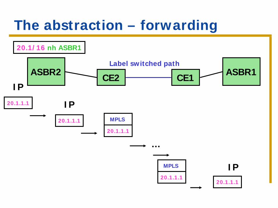
The abstraction – forwarding 20.1/16 nh ASBR1
ASBR2 ASBR1Label switched path
20.1.1.1
MPLS
CE2 CE1
20.1.1.1
IP20.1.1.1
IP
…
20.1.1.1
MPLS IP20.1.1.1
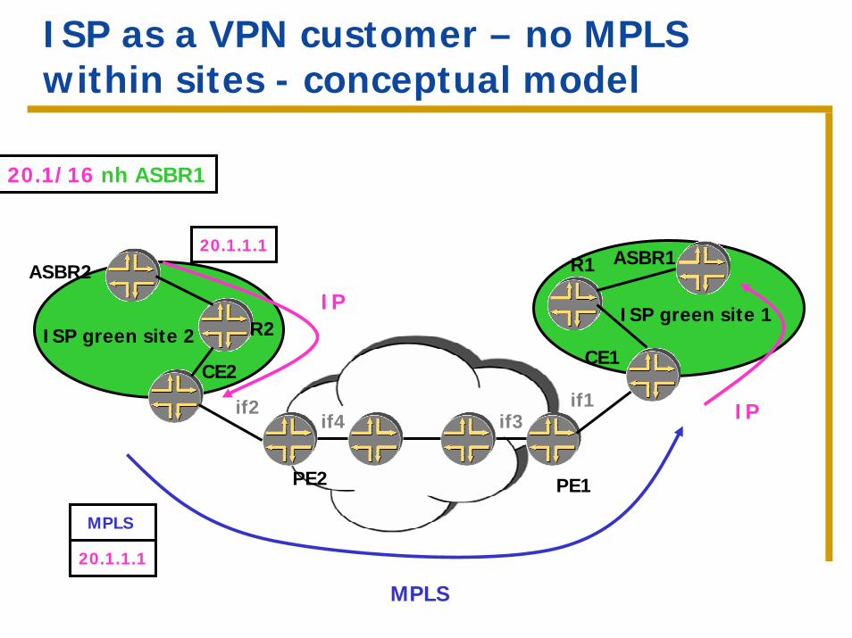
ISP as a VPN customer – no MPLS within sites - conceptual model
PE2
ASBR2
R2
CE2
PE1
ASBR1R1
CE1
if2 if1if3if4
20.1/16 nh ASBR1
20.1.1.1
IP
MPLS
20.1.1.1
MPLS
IP
ISP green site 2ISP green site 1
ISP as a VPN customer – step 2
The CE forwards the traffic over MPLS to the remote CE that will have an IP route for the external route.The local CE needs a label-switched-path to the remote CE. When the PE advertises the VPN routes to the CE, it also advertises a label for them. This extends MPLS to the CE. We are using this label to pick the next-hop on the PE.
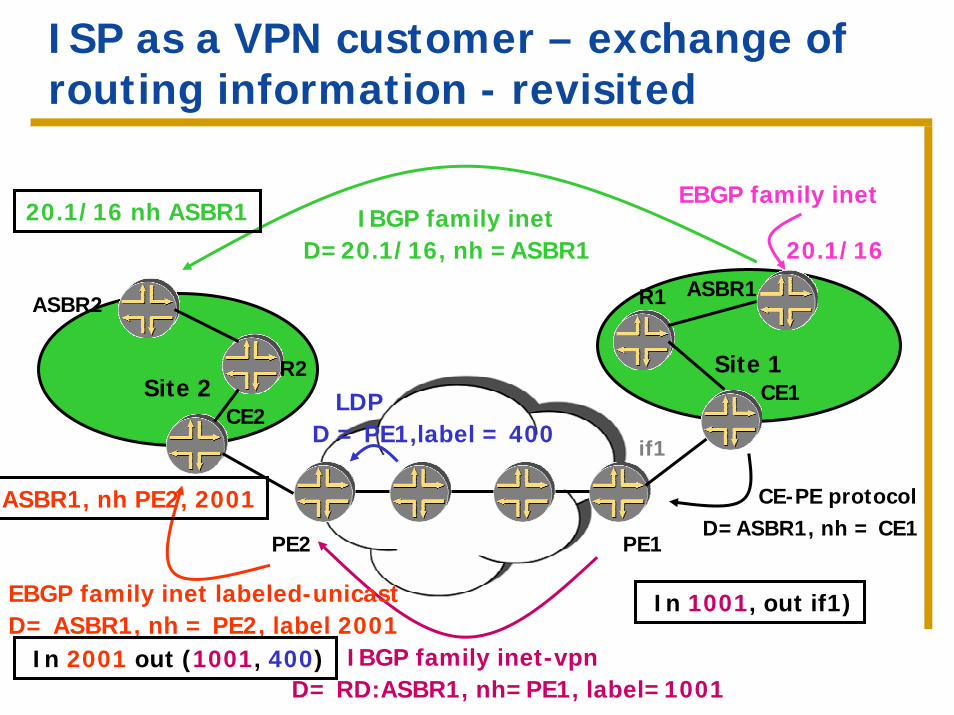
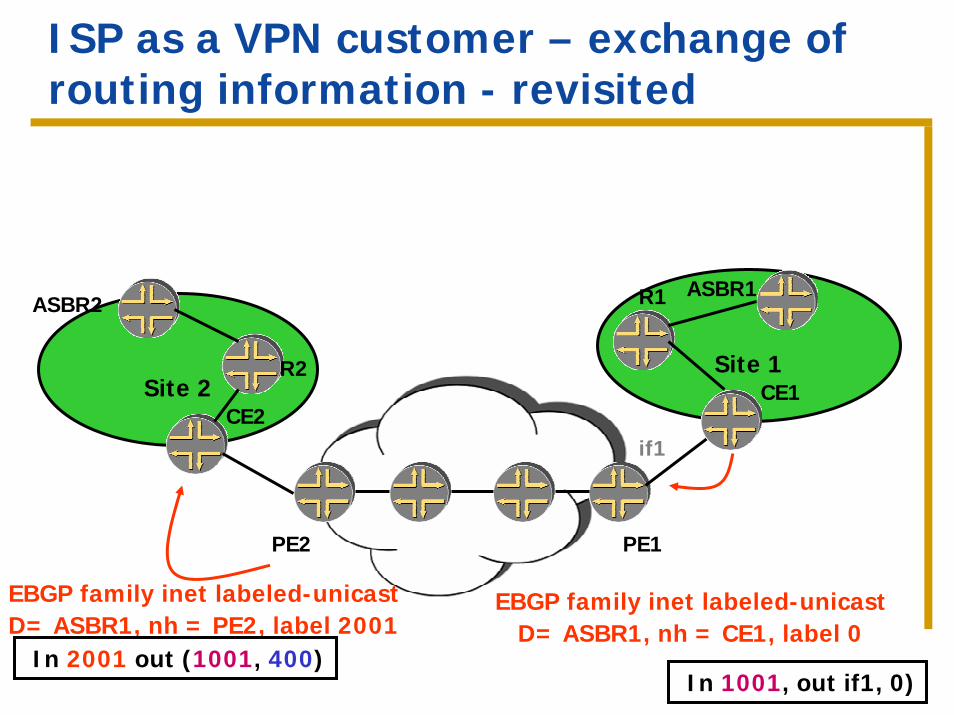
ISP as a VPN customer – exchange of routing information - revisited
Site 1
PE2
Site 2
ASBR2
R2
CE2
PE1
ASBR1R1
CE1
20.1/16
EBGP family inetIBGP family inet
D=20.1/16, nh =ASBR1
D= RD:ASBR1, nh=PE1, label=1001IBGP family inet-vpn
D=ASBR1, nh = CE1CE-PE protocol
LDPD = PE1,label = 400
EBGP family inet labeled-unicastD= ASBR1, nh = PE2, label 2001
20.1/16 nh ASBR1
ASBR1, nh PE2, 2001
In 2001 out (1001, 400)
In 1001, out if1)
if1
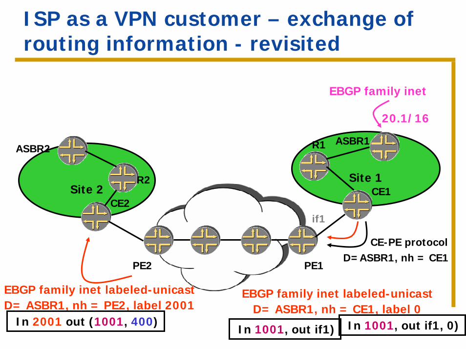
ISP as a VPN customer – exchange of routing information - revisited
Site 1
PE2
Site 2
ASBR2
R2
CE2
PE1
ASBR1R1
CE1
20.1/16
EBGP family inet
D=ASBR1, nh = CE1CE-PE protocol
EBGP family inet labeled-unicastD= ASBR1, nh = PE2, label 2001
In 2001 out (1001, 400)
if1
EBGP family inet labeled-unicastD= ASBR1, nh = CE1, label 0
In 1001, out if1) In 1001, out if1, 0)
ISP as a VPN customer – exchange of routing information - revisited
Site 1
PE2
Site 2
ASBR2
R2
CE2
PE1
ASBR1R1
CE1
EBGP family inet labeled-unicastD= ASBR1, nh = PE2, label 2001
In 2001 out (1001, 400)
if1
EBGP family inet labeled-unicastD= ASBR1, nh = CE1, label 0
In 1001, out if1, 0)
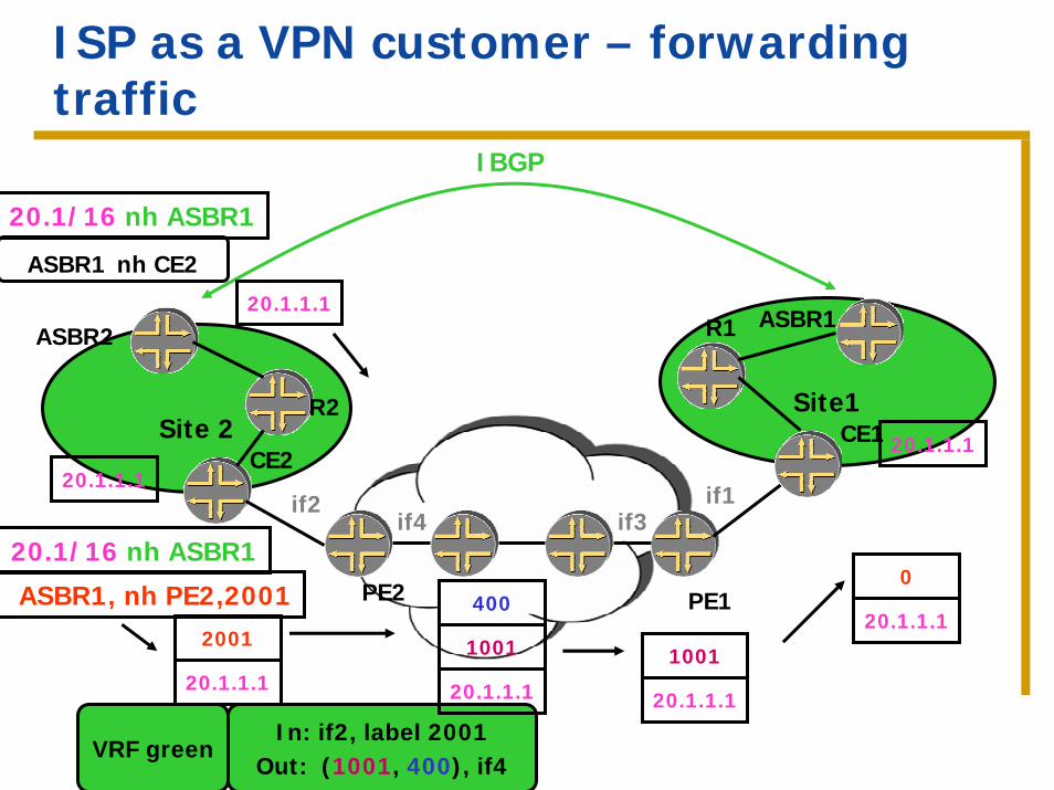
ISP as a VPN customer – forwarding traffic
Site1
PE2
Site 2
ASBR2
R2
CE2
PE1
ASBR1R1
CE1
IBGP
if2 if1
In: if2, label 2001Out: (1001, 400), if4
VRF green
if3if4
20.1/16 nh ASBR1
ASBR1 nh CE2
20.1.1.1
ASBR1, nh PE2,2001
20.1.1.1
2001
20.1.1.1
1001
400
20.1.1.1
20.1.1.1
1001
20.1/16 nh ASBR1
20.1.1.1
0
20.1.1.1
New concepts
The label is meaningful for the box that assigned it (it identifies the next-hop to be used for forwarding).
When assigning a new label, must install MPLS forwarding state. This stitches the two LSPs together.
ISP as a VPN customer – no MPLS within sites – summary
The VPN provider doesn’t carry the customer’s external routes in its backbone, it only carries the customer internal routes (BGP next-hops).
A labeled-switched path is established between the remote CEs.
The IP traffic to external destinations travels over this label-switched-path to the remote CE.
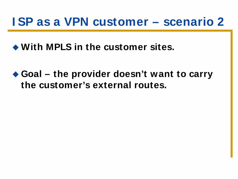
ISP as a VPN customer – scenario 2
With MPLS in the customer sites.
Goal – the provider doesn’t want to carry the customer’s external routes.
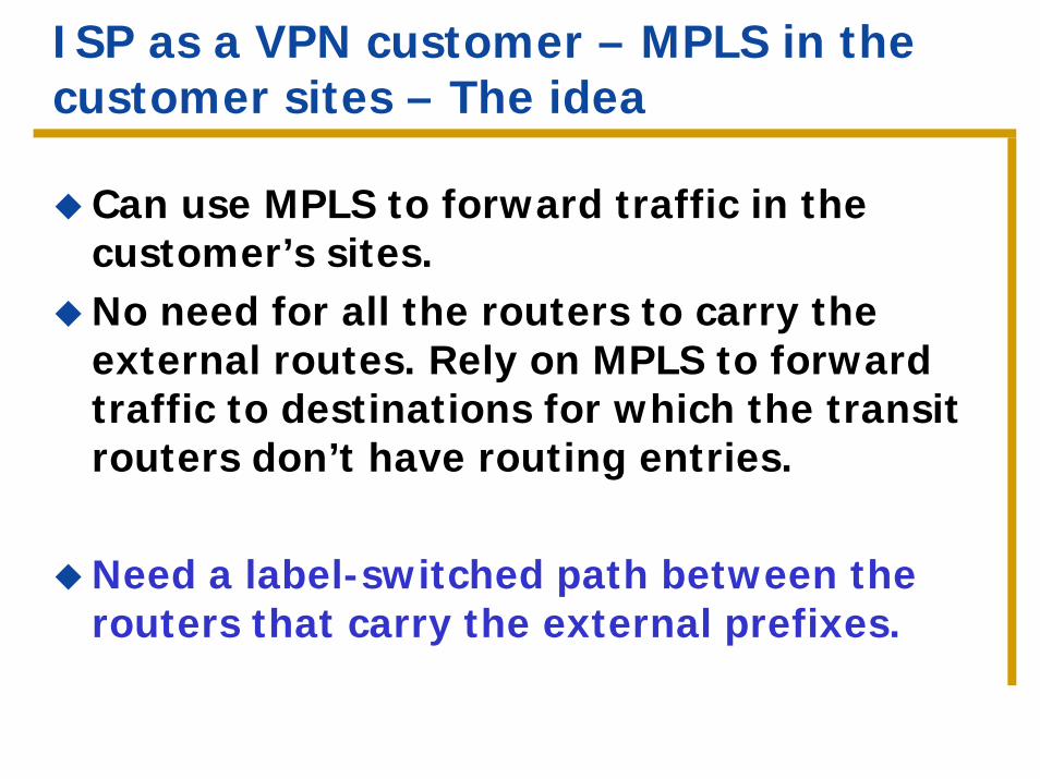
ISP as a VPN customer – MPLS in the customer sites – The idea
Can use MPLS to forward traffic in the customer’s sites.No need for all the routers to carry the external routes. Rely on MPLS to forward traffic to destinations for which the transit routers don’t have routing entries.
Need a label-switched path between the routers that carry the external prefixes.
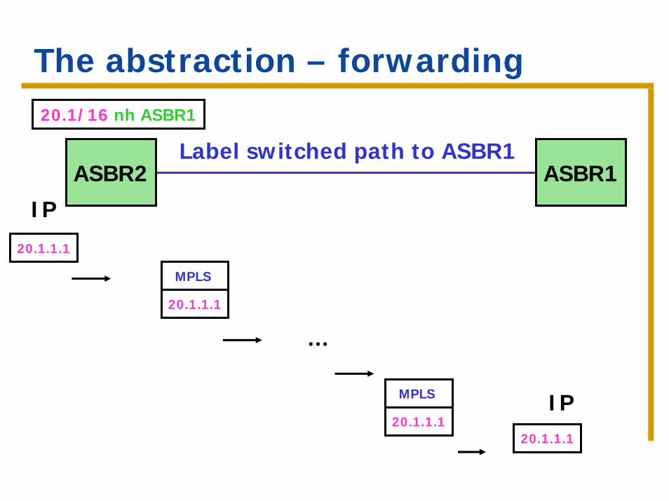
The abstraction – forwarding20.1/16 nh ASBR1
ASBR2 ASBR1Label switched path to ASBR1
20.1.1.1
IP
20.1.1.1
MPLS
…
20.1.1.1
MPLS IP20.1.1.1
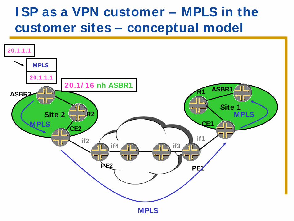
ISP as a VPN customer – MPLS in the customer sites – conceptual model
Site 1
PE2
Site 2
ASBR2
R2
CE2
PE1
ASBR1R1
CE1
if2 if1if3if4
20.1/16 nh ASBR1
MPLS
20.1.1.1
20.1.1.1
MPLS
MPLS
MPLS
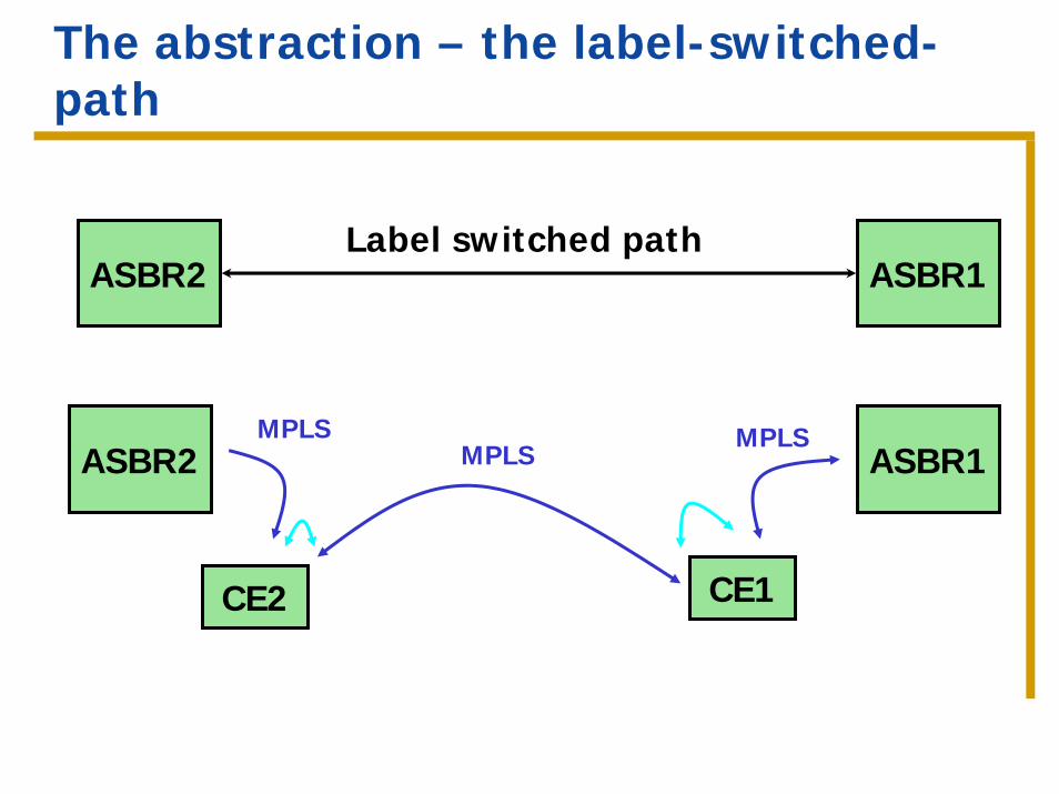
The abstraction – the label-switched-path
Label switched pathASBR2 ASBR1
ASBR2
CE2
ASBR1MPLS
CE1
MPLSMPLS
ISP as a VPN customer – with MPLS in the customer sites
The label-switched path between the ASBRs is made up of several segments.
In the previous scenario we saw how to establish a CE-CE label-switched path.
Need to stitch the CE-CE path with the CE-ASBR paths.
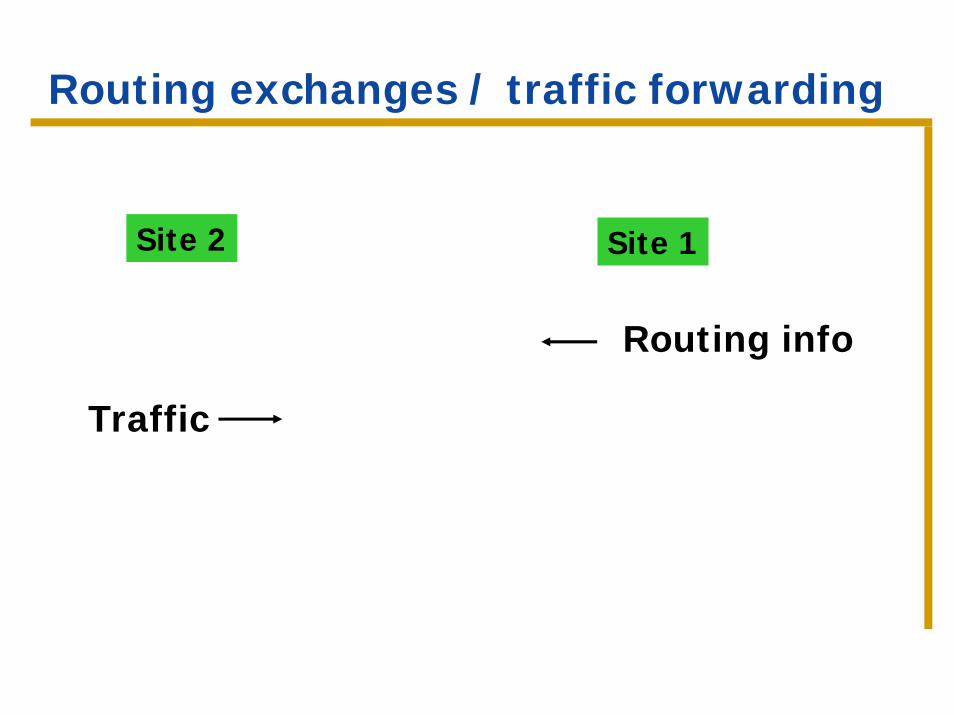
Routing exchanges / traffic forwarding
Site 2 Site 1
Routing info
Traffic
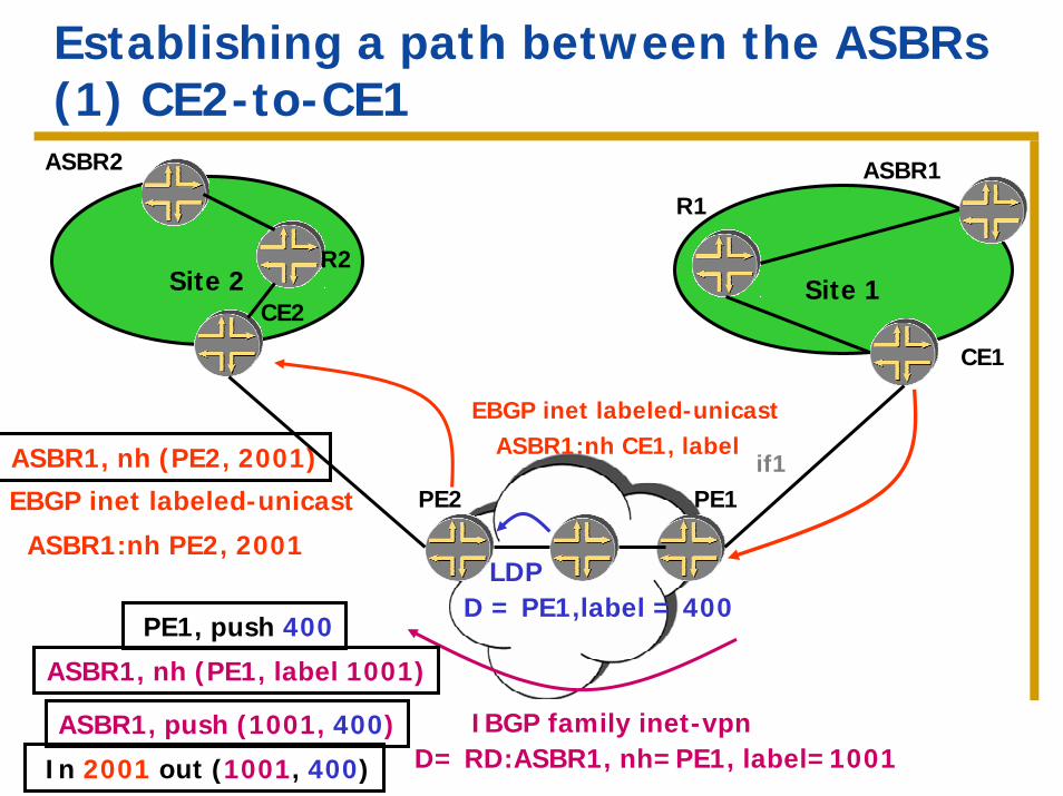
Establishing a path between the ASBRs(1) CE2-to-CE1
Site 1
PE2
Site 2
ASBR2
R2
CE2
PE1
ASBR1R1
CE1
D= RD:ASBR1, nh=PE1, label=1001IBGP family inet-vpn
ASBR1, nh (PE2, 2001)
LDPD = PE1,label = 400
EBGP inet labeled-unicast
ASBR1:nh PE2, 2001
if1
PE1, push 400
In 2001 out (1001, 400)
ASBR1, nh (PE1, label 1001)
ASBR1, push (1001, 400)
ASBR1:nh CE1, labelEBGP inet labeled-unicast
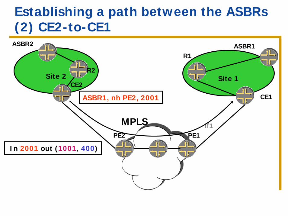
Establishing a path between the ASBRs(2) CE2-to-CE1
Site 1
PE2
Site 2
ASBR2
R2
CE2
PE1
ASBR1R1
CE1
In 2001 out (1001, 400)
ASBR1, nh PE2, 2001
if1MPLS
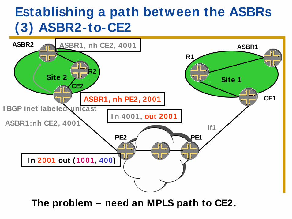
Establishing a path between the ASBRs(3) ASBR2-to-CE2
Site 1
PE2
Site 2
ASBR2
R2
CE2
PE1
ASBR1R1
CE1
In 2001 out (1001, 400)
ASBR1, nh PE2, 2001
if1
IBGP inet labeled-unicast
ASBR1:nh CE2, 4001
ASBR1, nh CE2, 4001
In 4001, out 2001
The problem – need an MPLS path to CE2.
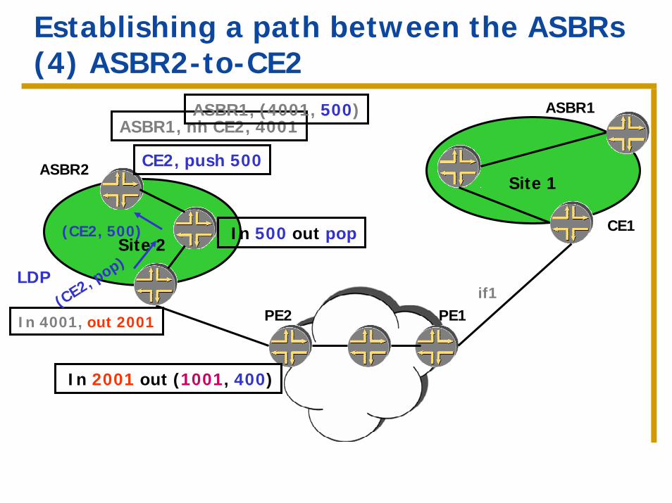
Establishing a path between the ASBRs(4) ASBR2-to-CE2
Site 1
PE2
CE2
PE1
ASBR1
CE1
In 2001 out (1001, 400)
In 4001, out 2001
if1
ASBR1, nh CE2, 4001
Site 2
ASBR2
(CE2, pop)
(CE2, 500)
LDP
CE2, push 500
ASBR1, (4001, 500)
In 500 out pop
ASBR2-to-CE2 – discussion
Requires a two label push at ASBR2.
One label identifies ASBR1, and the other label identifies the path to CE2 which is the router that injected ASBR1.
The route for ASBR1 doesn’t need to be known inside Site2.
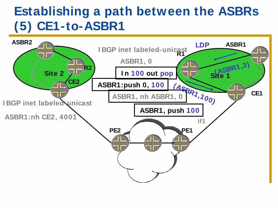
Establishing a path between the ASBRs(5) CE1-to-ASBR1
Site 1
PE2
Site 2
ASBR2
R2
CE2
PE1
ASBR1R1
CE1
if1
IBGP inet labeled-unicast
ASBR1:nh CE2, 4001
IBGP inet labeled-unicast
ASBR1, 0
ASBR1, nh ASBR1, 0
LDP
(ASBR1,3)
(ASBR1,100)
In 100 out pop
ASBR1, push 100
ASBR1:push 0, 100
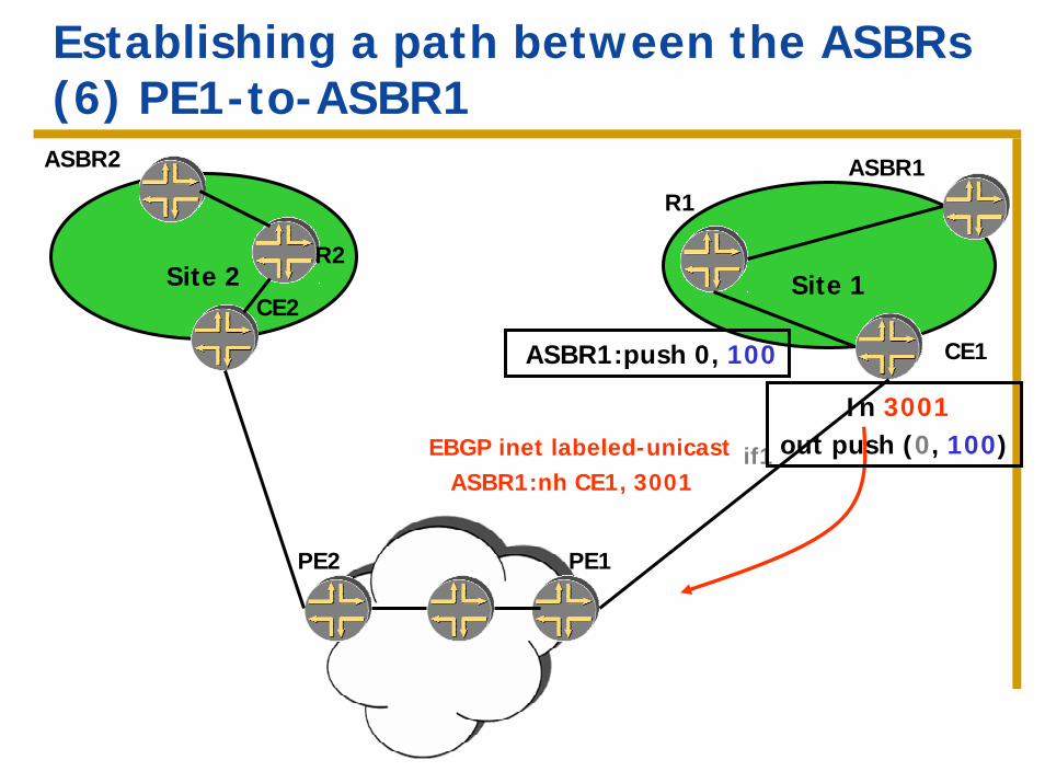
Establishing a path between the ASBRs(6) PE1-to-ASBR1
Site 1Site 2
ASBR2
R2
CE2
PE2 PE1
ASBR1R1
CE1
if1ASBR1:nh CE1, 3001
EBGP inet labeled-unicast
ASBR1:push 0, 100
In 3001out push (0, 100)
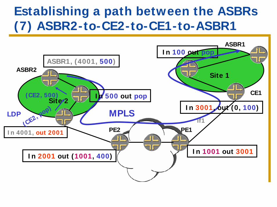
Establishing a path between the ASBRs(7) ASBR2-to-CE2-to-CE1-to-ASBR1
Site 1
PE2
CE2
PE1
ASBR1
CE1
In 2001 out (1001, 400)
In 4001, out 2001
if1
In 1001 out 3001
In 100 out pop
Site 2
ASBR2
(CE2, pop)
(CE2, 500)
LDP
ASBR1, (4001, 500)
MPLS
In 500 out pop
In 3001, out (0, 100)
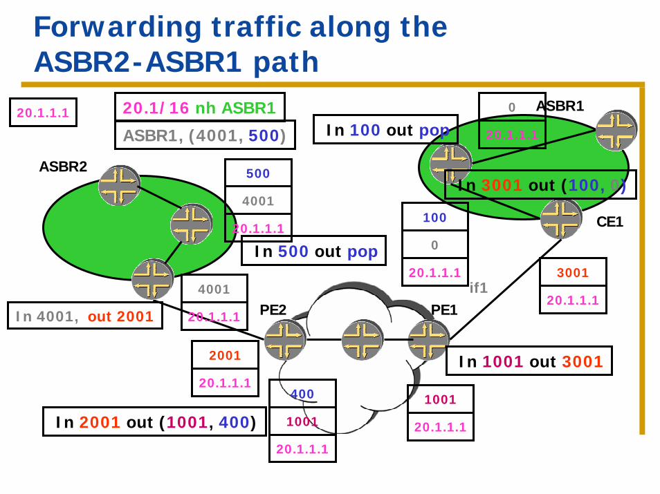
Forwarding traffic along the ASBR2-ASBR1 path
PE2
CE2
PE1
ASBR1
CE1
In 2001 out (1001, 400)
In 4001, out 2001
if1
In 3001 out (100, 0)
In 1001 out 3001
In 100 out pop
ASBR2
ASBR1, (4001, 500)
20.1/16 nh ASBR120.1.1.1
In 500 out pop
20.1.1.1
1001
40020.1.1.1
2001
20.1.1.1
4001
20.1.1.1
4001
500
20.1.1.1
1001
20.1.1.1
300120.1.1.1
100
0
20.1.1.1
0
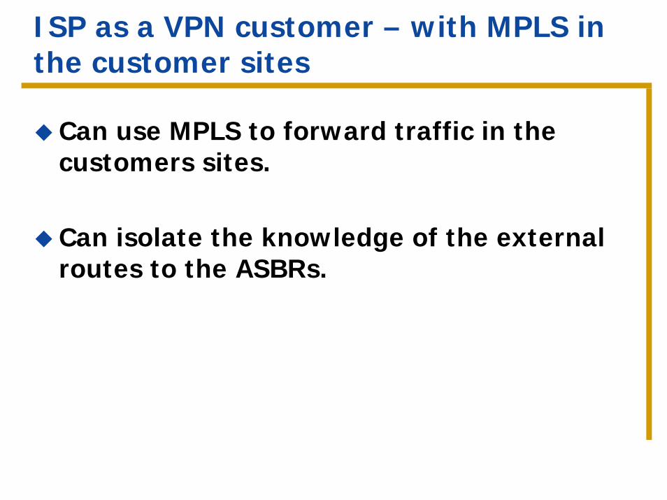
ISP as a VPN customer – with MPLS in the customer sites
Can use MPLS to forward traffic in the customers sites.
Can isolate the knowledge of the external routes to the ASBRs.
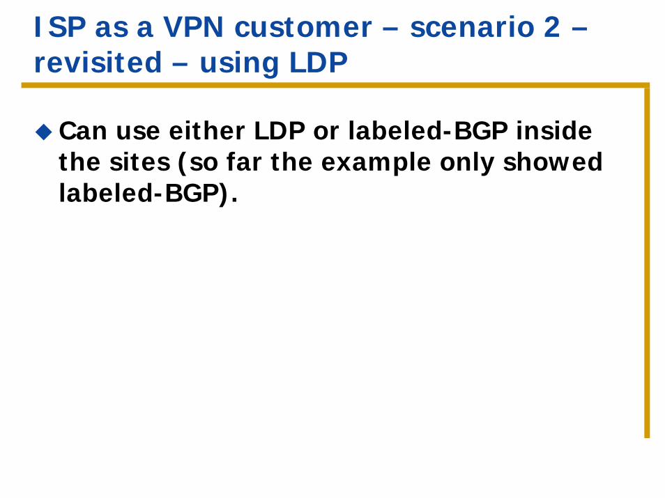
ISP as a VPN customer – scenario 2 –revisited – using LDP
Can use either LDP or labeled-BGP inside the sites (so far the example only showed labeled-BGP).
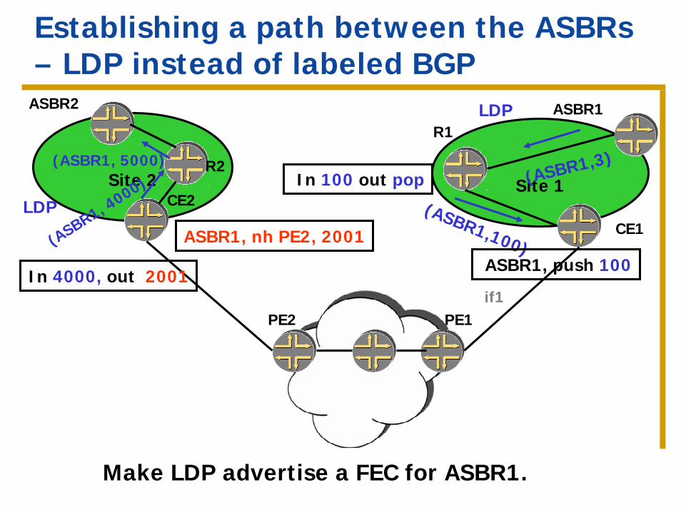
Establishing a path between the ASBRs– LDP instead of labeled BGP
Site 1
PE2
Site 2
ASBR2
R2
CE2
PE1
ASBR1R1
CE1
if1
LDP
(ASBR1,3)
(ASBR1,100)
In 100 out pop
ASBR1, push 100(ASBR1, 4
000)(ASBR1, 5000)
LDP
ASBR1, nh PE2, 2001
In 4000, out 2001
Make LDP advertise a FEC for ASBR1.
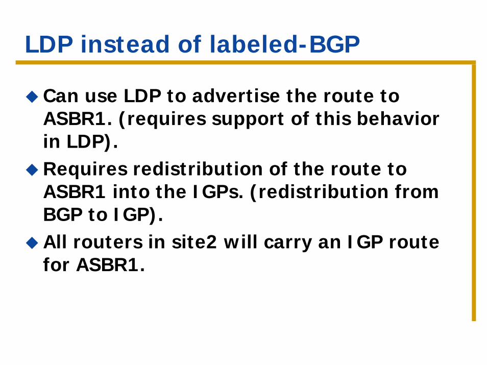
LDP instead of labeled-BGP
Can use LDP to advertise the route to ASBR1. (requires support of this behavior in LDP).Requires redistribution of the route to ASBR1 into the IGPs. (redistribution from BGP to IGP).All routers in site2 will carry an IGP route for ASBR1.
Part 2 – Hierarchical and recursive applications
IntroductionISP as a VPN customerVPN service provider as a VPN customerVPN services across AS boundaries
VPN service provider as a VPN customer
Goal: provide connectivity for geographically dispersed sites of a VPN service provider.
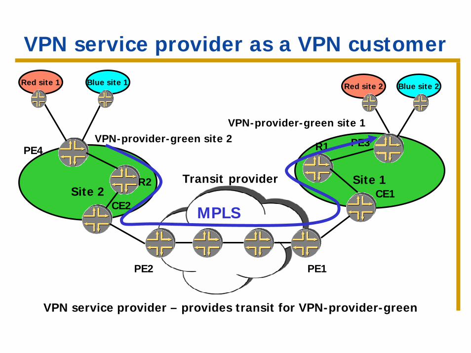
VPN service provider as a VPN customer
Site 1Site 2
PE4
R2
CE2
VPN-provider-green site 2 PE3R1
CE1
VPN-provider-green site 1
Blue site 1 Red site 2 Blue site 2Red site 1
PE2 PE1
Transit provider
MPLS
VPN service provider – provides transit for VPN-provider-green
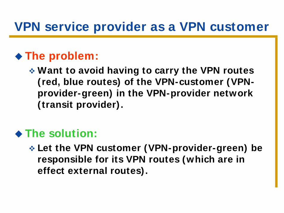
VPN service provider as a VPN customer
The problem:Want to avoid having to carry the VPN routes (red, blue routes) of the VPN-customer (VPN-provider-green) in the VPN-provider network (transit provider).
The solution:Let the VPN customer (VPN-provider-green) be responsible for its VPN routes (which are in effect external routes).
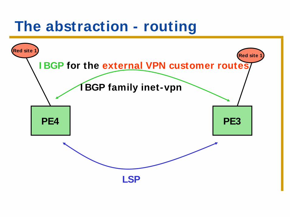
The abstraction - routing
PE4 PE3
IBGP for the external VPN customer routes
Red site 1Red site 1
IBGP family inet-vpn
LSP
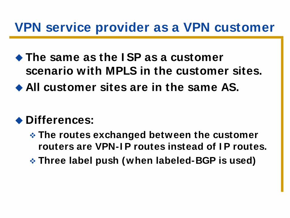
VPN service provider as a VPN customer
The same as the ISP as a customer scenario with MPLS in the customer sites.All customer sites are in the same AS.
Differences:The routes exchanged between the customer routers are VPN-IP routes instead of IP routes.Three label push (when labeled-BGP is used)

Routing exchanges / traffic forwarding
Site 2 Site 1
Routing info
Traffic
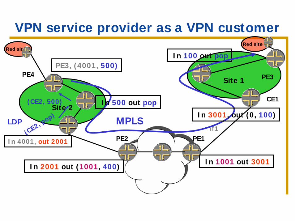
VPN service provider as a VPN customer
Site 1
PE2
CE2
PE1
PE3
CE1
In 2001 out (1001, 400)
In 4001, out 2001
if1
In 1001 out 3001
In 100 out pop
Site 2
PE4
(CE2, pop)
(CE2, 500)
LDP
PE3, (4001, 500)
MPLS
In 500 out pop
In 3001, out (0, 100)
Red site 1Red site 1
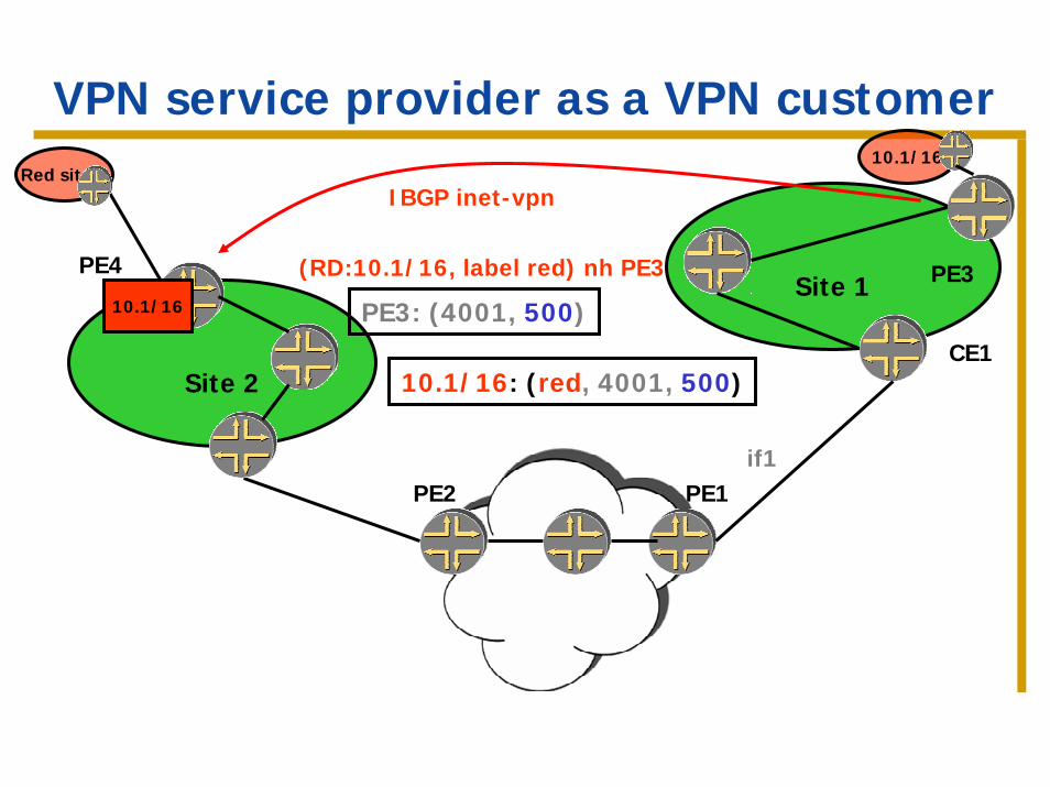
VPN service provider as a VPN customer
Site 1
PE2
CE2
PE1
PE3
CE1
if1
Site 2
PE4
Red site 110.1/16
(RD:10.1/16, label red) nh PE310.1/16
IBGP inet-vpn
PE3: (4001, 500)
10.1/16: (red, 4001, 500)
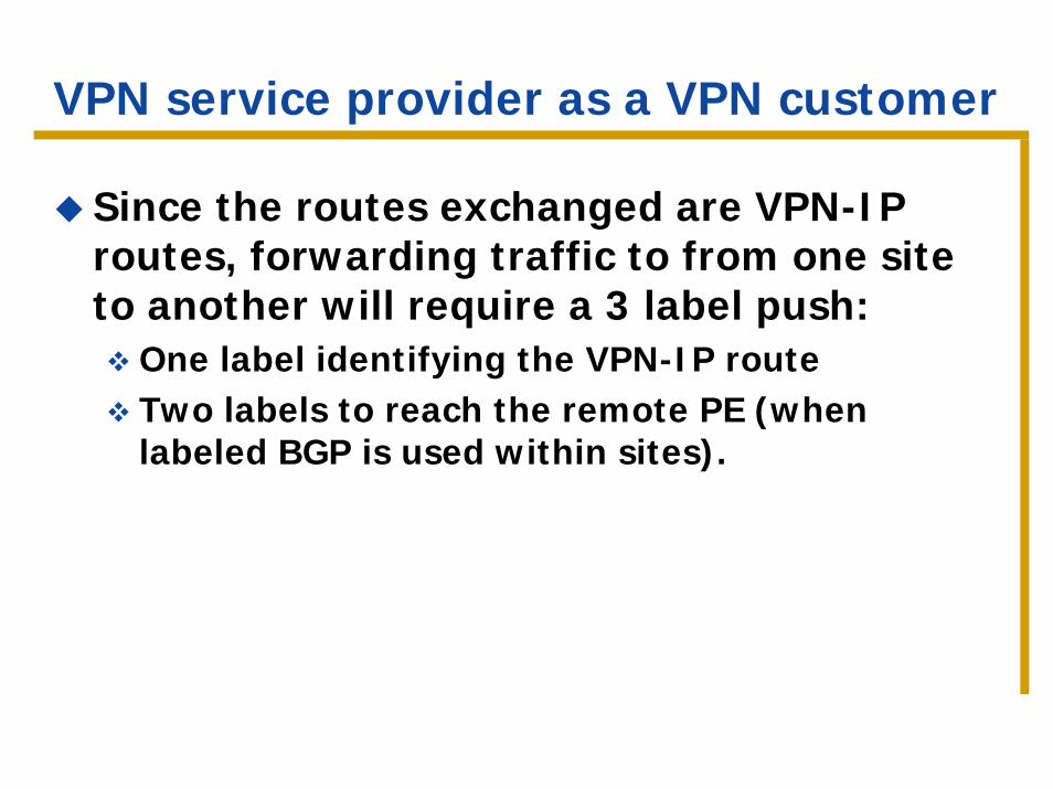
VPN service provider as a VPN customer
Since the routes exchanged are VPN-IP routes, forwarding traffic to from one site to another will require a 3 label push:
One label identifying the VPN-IP routeTwo labels to reach the remote PE (when labeled BGP is used within sites).
Part 2 – Hierarchical and recursive applications
IntroductionISP as a VPN customerVPN service provider as a VPN customerVPN services across AS boundaries
VPN services across AS boundaries
So far we’ve seen examples where all sites in a VPN are connected to the same AS.
What if not all sites are in the same AS?
Useful if:VPN sites are connected to different providersThe provider’s backbone is partitioned among different AS.
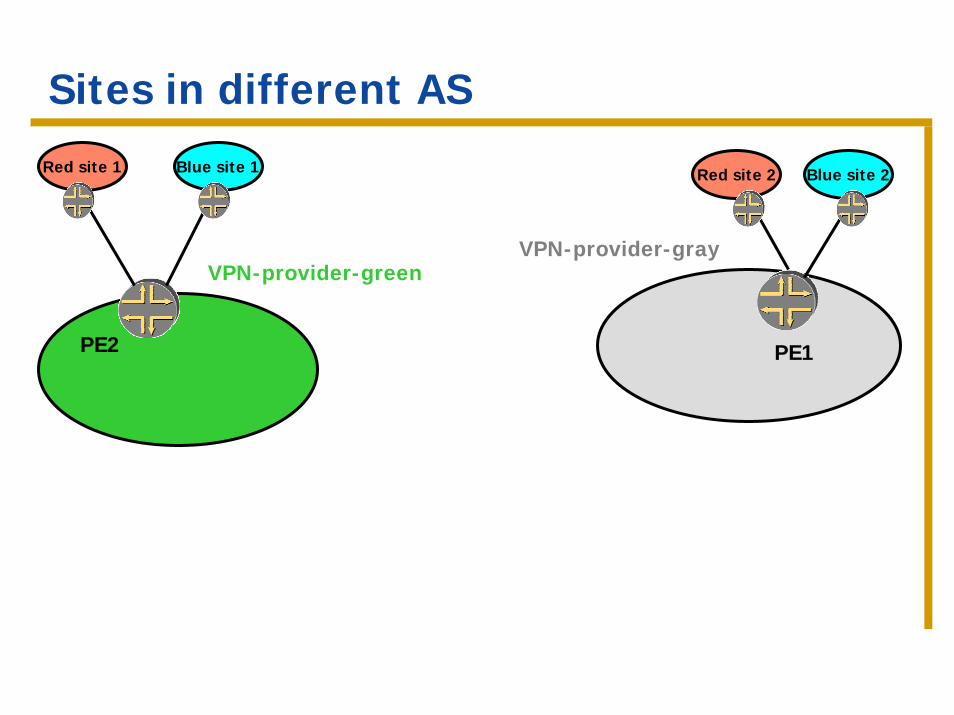
Sites in different AS
Blue site 1Red site 1 Red site 2 Blue site 2
PE2
VPN-provider-green
PE1
VPN-provider-gray
VPN services across AS boundaries
The problem – can’t run IBGP between the remote sites anymore.
The solutions:Discussed in section 10 of 2547bis and referred to as “Option a”, “Option b” and “Option c”.
Option A – VRF-to-VRF connections
A PE router in one AS attaches directly to a PE router in another AS. There are several interfaces between the PEs, one for each VPN whose routes are passed between AS.Each PE treats the other as a CE and exchanges the VPN routes using EBGP on a per-VRF basis.
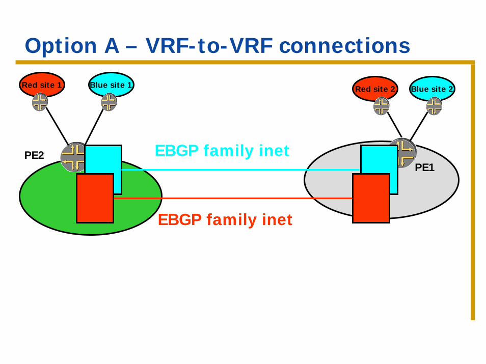
Option A – VRF-to-VRF connections
PE2PE1
Blue site 1Red site 1 Red site 2 Blue site 2
EBGP family inet
EBGP family inet
Option A – VRF-to-VRF connections
Major scaling issues:All VPN routes are exchanged.Multiple EBGP sessions need to be maintained. The ASBRs must carry a large number of routes.
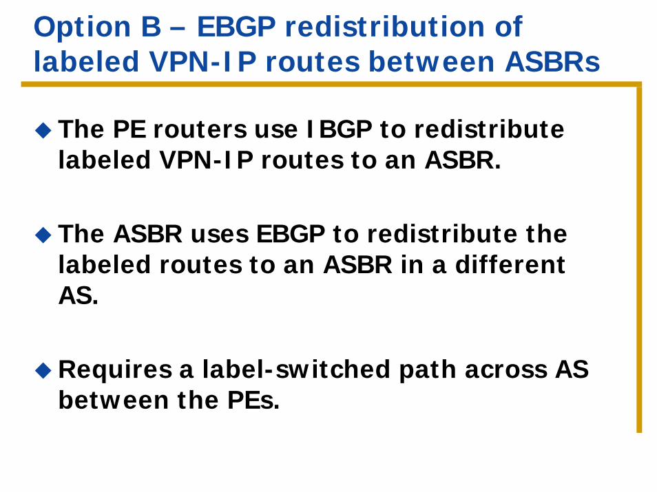
Option B – EBGP redistribution of labeled VPN-IP routes between ASBRs
The PE routers use IBGP to redistribute labeled VPN-IP routes to an ASBR.
The ASBR uses EBGP to redistribute the labeled routes to an ASBR in a different AS.
Requires a label-switched path across AS between the PEs.
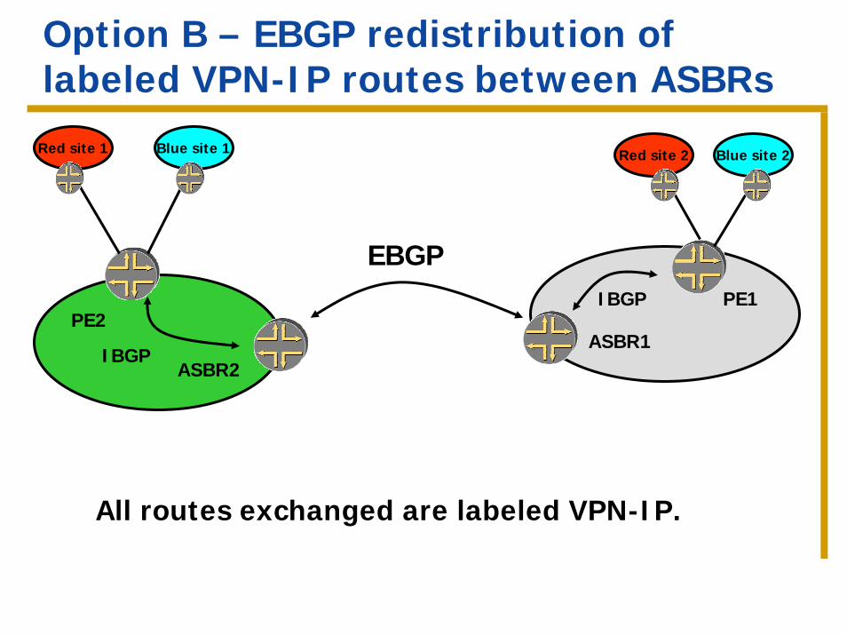
Option B – EBGP redistribution of labeled VPN-IP routes between ASBRs
PE2PE1
Blue site 1Red site 1 Red site 2 Blue site 2
ASBR1ASBR2
EBGP IBGP
IBGP
All routes exchanged are labeled VPN-IP.
Option B – EBGP redistribution of labeled VPN-IP routes between ASBRs
More scalable than option A:No need for per/VPN configuration at the ASBRs.
Still exchange all the VPN routes.
Requires an inter-AS LSP between the two PEs.
Option C – EBGP redistribution of labeled VPN-IP routes between PEs
In both option A and option BAll VPN routes are exchanged. The scalability is determined by the amount of VPN routing information. The load on the ASBRs is determined by the amount of VPN information carried.
Option C – use multi-hop EBGP to distribute the VPN-IP routes between the PEs. The ASBRsexchange the internal routes, not the VPN routes.
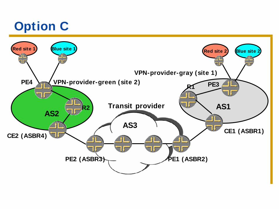
Option C
AS1AS2
PE4
R2
CE2 (ASBR4)
VPN-provider-green (site 2) PE3R1
CE1 (ASBR1)
VPN-provider-gray (site 1)
Blue site 1Red site 1 Red site 2 Blue site 2
Transit provider
AS3
PE2 (ASBR3) PE1 (ASBR2)
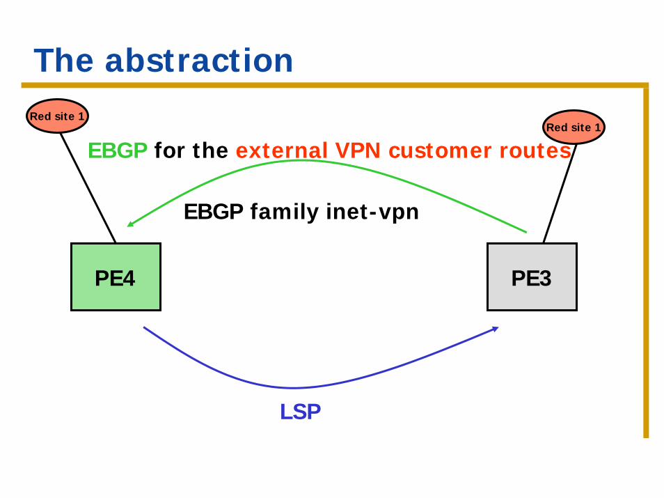
The abstraction
PE4 PE3
EBGP for the external VPN customer routes
Red site 1Red site 1
EBGP family inet-vpn
LSP
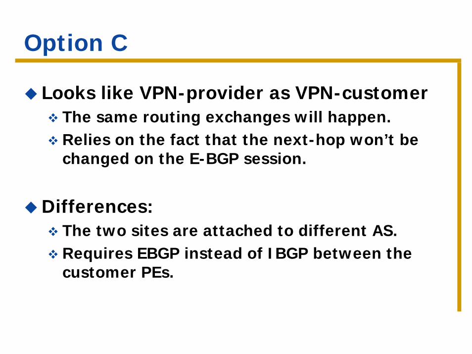
Option C
Looks like VPN-provider as VPN-customerThe same routing exchanges will happen.Relies on the fact that the next-hop won’t be changed on the E-BGP session.
Differences:The two sites are attached to different AS.Requires EBGP instead of IBGP between the customer PEs.