bew engineering - florida solar energy center · bew engineering timothy zgonena ... ul 467...
TRANSCRIPT

Solar America Board for Codes and Standardswww.solarabcs.org
Photovoltaic Module Grounding:
Issues and Recommendations
Prepared by:
Greg BallBEW Engineering
Timothy ZgonenaChristopher Flueckiger
Underwriters Laboratories Inc.
April 2012

1Solar America Board for Codes and Standards Report
DisclaimerThis report was prepared as an account of work sponsored by an agency of the United States government. Neither the United States government nor any agency thereof, nor any of their employees, makes any warranty, express or implied, or assumes any legal liability or responsibility for the accuracy, completeness, or usefulness of any information, apparatus, product, or process disclosed, or represents that its use would not infringe privately owned rights. Reference herein to any specific commercial product, process, or service by trade name, trademark, manufacturer, or otherwise does not necessarily constitute or imply its endorsement, recommendation, or favoring by the United States government or any agency thereof. The views and opinions of authors expressed herein do not necessarily state or reflect those of the United States government or any agency thereof.
Download a copy of the report:www.solarabcs.org/grounding

2P Photovoltaic Module Grounding: Issues and Recommendations
Executive Summary
This is the second and final report of a study addressing the electrical grounding of photovoltaic (PV) modules. The Solar America Board for Codes and Standards (Solar ABCs), with support from the U.S. Department of Energy, commissioned this study to provide the PV industry with practical guidelines and procedures for module grounding in the overall context of system grounding. This report also makes recommendations for improving the technical standards that certify the modules and related grounding components. Solar ABCs published an interim “Lay of the Land” report on the topic in the spring of 2011, which described the many issues facing industry stakeholders. This final report draws on feedback from the PV industry as well as on research performed at Underwriters Laboratories (UL) to develop guidelines and recommend changes to existing codes and standards.
There are two fundamental module grounding issues facing the industry. The first is that there are limited numbers of approved (listed) grounding methods, despite a wide variety of installation methods for grounding module frames. Currently there is much developmental activity on three UL standards that will clarify the listing issue. UL 1703 (Flat-Plate Photovoltaic Modules and Panels) (UL, 2002), the primary governing standard for modules and their grounding, is being revised to make the standard clearer and to provide enhanced testing guidelines. These revisions are not only for module manufacturers—the chief users of the standard—but also for third-party suppliers of grounding components. UL 467 (Grounding and Bonding Equipment) (UL, 2004) as historically been used by some grounding component manufacturers but is not officially recognized as applicable to PV module applications. UL 2703 (Rack Mounting Systems and Clamping Devices for Flat-Plate Photovoltaic Modules and Panels) (UL, 2011) is a draft standard that addresses system level mounting configurations and uses much the same grounding language as UL 1703. The revisions and improvements to these standards are still in progress, but there is clear momentum and direction for resolving the problems that have led to inconsistent understanding and interpretation.
The second issue is the lack of confidence in existing approved grounding methods, due largely to failures in the field from loss of mechanical integrity, installation error, and damage from corrosion. We present details of a recent UL paper (Wang, Yen, Wang, Ji, & Zgonena, 2011), which is included in its entirety as Appendix A. In the study, different types of PV grounding connectors were collected, installed, and tested in accelerated environmental chambers using both continuous damp heat and salt mist environmental exposure. The effects of current cycling, assembly force, and anti-oxidation coating application on grounding reliability were evaluated in conjunction with aging tests.
Under the salt mist condition, most of the samples were severely corroded and failed within weeks, while identical samples in the damp heat chamber were still in good condition. UL is working to determine how these tests should be integrated into UL 1703 and 2703, recognizing that the existing base of standard tests sometimes fails to reveal issues encountered in the field, while extreme laboratory conditions may cause failure modes that will not be seen in actual installations.
A UL 1703 subcommittee is investigating the possible adoption of language from an upcoming revision of International Electrotechnical Commission (IEC) 61701 (Edition 2) titled “Salt mist corrosion testing of photovoltaic (PV) modules,” which specifically addresses testing issues specific to PV module frames. Solar ABCs will publish an addendum to this report in the spring of 2012 to update industry activities and direction in this area.
“This report makes recommenda-tions for improving the technical stan-
dards that certify the modules and related grounding components. ”

3Solar America Board for Codes and Standards Report
Recommended current tests identified in this report mirror the conclusions of a UL 1703 Standards Technical Panel (STP) subcommittee charged with developing new language for the Bonding and Grounding section. These tests combine existing low current tests with tests derived from UL 467 that are designed to ensure proper operation of overcurrent protection devices.
In addition, we consider personnel safety in this report. We explore various fault scenarios in conjunction with IEC data describing body impedances and harmful levels of current to provide generalized methods of evaluating ground resistance limits. We also discuss more generalized design criteria using National Electrical Code principles. From a listing standpoint, the current test regimes recommended here should adequately address safety issues such as touch safe voltages and currents.
UL 1703 and UL 2703 are still undergoing significant change, so this report concludes with general recommendations for ensuring proper grounds based on field experience and feedback received throughout the course of this study.
The general recommendations from this report include:
• Complete the proposed changes to the existing standards to improve the method and quality of ground connections.
• Elicit additional industry feedback from the accelerated aging test study to determine if and how these or similar tests might be incorporated into standard testing.
• Be aware of and make use of the new and expanded set of channels for listing module grounding equipment.
• Be aware of the principles of module frame grounding, the type of faults that may occur, and the implications for safety and ground system design.
• Follow the specific design and installation recommendations enumerated in this report, such as using proper materials and components, following manufacturer instructions, using torque wrenches to ensure proper tightening of connections, and avoiding connections of dissimilar metals that lead to corrosion, among others.

4P Photovoltaic Module Grounding: Issues and Recommendations
Table of Contents
DISCLAIMER ....................................................................................................................... 1
EXECUTIVE SUMMARY ...................................................................................................... 2
AUTHOR BIOGRAPHIES .................................................................................................... 5
SOLAR AMERICA BOARD FOR CODES AND STANDARDS .............................................. 5
ACKNOWLEDGEMENT ....................................................................................................... 5
INTRODUCTION ................................................................................................................. 6
Existing Standards—Summary and Updates ............................................................ 7
RECOMMENDATIONS FOR ENHANCED TESTING ...................................................9
Current Tests .............................................................................................................. 10
Accelerated Aging and Corrosion Resistance Tests ................................................ 11
MODULE GROUNDING AND SAFETY UNDER FAULT CONDITIONS ............................. 15
Electricity and the Human Body .............................................................................. 15
Module Frame Fault Scenarios ................................................................................. 18
Implications of a Frame Grounding Approach ....................................................... 21
RECOMMENDATIONS FOR INSTALLATIONS ................................................................. 23
REFERENCES .................................................................................................................... 25
RESOURCES .............................................................................................................25
APPENDIX A: Accelerated Aging Tests on PV Grounding Connections ....................... 26
ACRONYMS ...................................................................................................................... 35
5Solar America Board for Codes and Standards Report
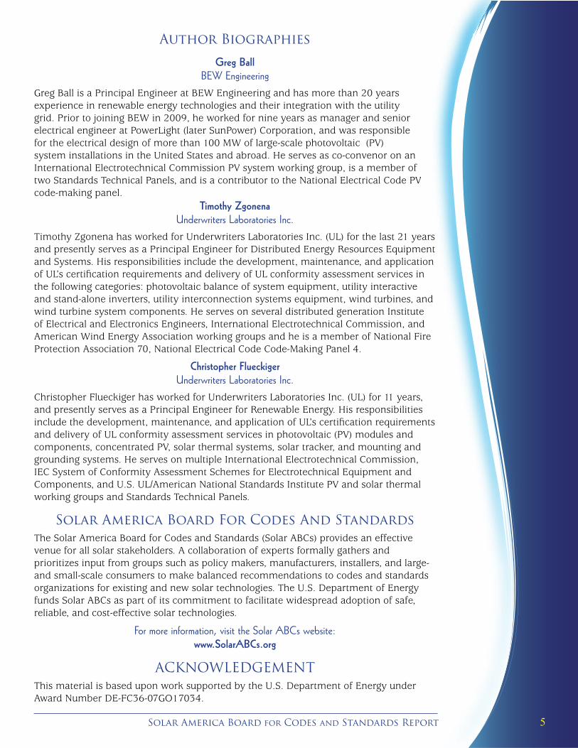
Author Biographies
Greg BallBEW Engineering
Greg Ball is a Principal Engineer at BEW Engineering and has more than 20 years experience in renewable energy technologies and their integration with the utility grid. Prior to joining BEW in 2009, he worked for nine years as manager and senior electrical engineer at PowerLight (later SunPower) Corporation, and was responsible for the electrical design of more than 100 MW of large-scale photovoltaic (PV) system installations in the United States and abroad. He serves as co-convenor on an International Electrotechnical Commission PV system working group, is a member of two Standards Technical Panels, and is a contributor to the National Electrical Code PV code-making panel.
Timothy ZgonenaUnderwriters Laboratories Inc.
Timothy Zgonena has worked for Underwriters Laboratories Inc. (UL) for the last 21 years and presently serves as a Principal Engineer for Distributed Energy Resources Equipment and Systems. His responsibilities include the development, maintenance, and application of UL’s certification requirements and delivery of UL conformity assessment services in the following categories: photovoltaic balance of system equipment, utility interactive and stand-alone inverters, utility interconnection systems equipment, wind turbines, and wind turbine system components. He serves on several distributed generation Institute of Electrical and Electronics Engineers, International Electrotechnical Commission, and American Wind Energy Association working groups and he is a member of National Fire Protection Association 70, National Electrical Code Code-Making Panel 4.
Christopher FlueckigerUnderwriters Laboratories Inc.
Christopher Flueckiger has worked for Underwriters Laboratories Inc. (UL) for 11 years, and presently serves as a Principal Engineer for Renewable Energy. His responsibilities include the development, maintenance, and application of UL’s certification requirements and delivery of UL conformity assessment services in photovoltaic (PV) modules and components, concentrated PV, solar thermal systems, solar tracker, and mounting and grounding systems. He serves on multiple International Electrotechnical Commission, IEC System of Conformity Assessment Schemes for Electrotechnical Equipment and Components, and U.S. UL/American National Standards Institute PV and solar thermal working groups and Standards Technical Panels.
Solar America Board For Codes And StandardsThe Solar America Board for Codes and Standards (Solar ABCs) provides an effective venue for all solar stakeholders. A collaboration of experts formally gathers and prioritizes input from groups such as policy makers, manufacturers, installers, and large- and small-scale consumers to make balanced recommendations to codes and standards organizations for existing and new solar technologies. The U.S. Department of Energy funds Solar ABCs as part of its commitment to facilitate widespread adoption of safe, reliable, and cost-effective solar technologies.
For more information, visit the Solar ABCs website: www.SolarABCs.org
ACKNOWLEDGEMENTThis material is based upon work supported by the U.S. Department of Energy under Award Number DE-FC36-07GO17034.

6P Photovoltaic Module Grounding: Issues and Recommendations
INTRODUCTION
This is the final report of a study of photovoltaic (PV) module grounding issues. The need for this study was identified through a gap analysis completed by Solar ABCs with input from many U.S. stakeholders.
PV modules are typically installed on aluminum or galvanized, painted, or stainless steel frame structures. These structures and any other electrically conductive components that could become energized by the PV array (or other electricity sources) and that could be accessible during routine servicing must be bonded to ensure safe touch voltages. In their installation manuals, module manufacturers currently provide detailed directions but limited options for grounding the modules. Other options are available—manufacturers have developed components designed for grounding PV modules and have pursued different approaches for certifying or listing these devices. There is little industry consensus, however, on the appropriateness or completeness of the available standards for these general use components.
The result has been a large number of fielded systems that demonstrate:
• unsatisfactory module grounding measures, broadly characterized as those in which electrical continuity is jeopardized or has failed,
• violations of the module’s Underwriters Laboratories Inc. (UL) 1703 listing because the installation does not comply with the installation manual’s prescribed method of grounding the module frame,
• incorporation of components listed to more general grounding equipment standards that may or may not be completely suitable for the application, and/or
• well-engineered grounding measures using methods or component systems that together were not listed or had no reasonable process for certification through UL 1703.
The overall module grounding study attempts to address these issues with the following steps:
• Publish an interim Lay of the Land report, a survey of the existing situation in which stakeholders (system designers, module and component manufacturers, Nationally Recognized Testing Laboratories [NRTLs], and researchers) shared their experiences and recommendations to address the issues listed above. This interim report was published in the spring of 2011.
• Evaluate existing and new test procedures. This was primarily a UL-led effort to investigate expanded or enhanced current and accelerated aging test methods that can provide greater confidence in the long-term reliability of grounding methods.
• Develop this final report, incorporating results and feedback from prior efforts. This report makes final recommendations for new or expanded tests to incorporate into standards, and documents guidelines and procedures for public use.
The enhanced accelerated aging test methods are intended to better evaluate the long-term reliability of the connections to and between metal parts in a PV array, applicable to any roof- or ground-mounted system, whether the mounting structure is metallic or not.
This report also provides some practical guidance for system designers, installers, and trainers by describing effective and durable module frame grounds that can be confidently approved by building inspectors and other authorities having jurisdiction (AHJs).
Throughout this document, the terms “ground,” “grounding,” and “grounded” are used to describe the connections to module frames that are the primary focus of the study.

7Solar America Board for Codes and Standards Report
Note that there is a distinction between “grounded” and “bonded.” Article 100 of the 2011 National Electric Code (NEC) (National Electrical Code, 2011) defines these terms as follows:
• Grounded: Connected to ground or to a conducting body that extends the ground connection.
• Bonded: Connected to establish electrical continuity and conductivity.
Much of the scope of this study focuses on the bonding of frames to other parts or conductors that are then grounded. This report uses the more general “grounding” term to describe both bonding and grounding unless bonding is specifically called out.
The topic of PV system grounding covers a wide range of issues outside the scope of this particular study, including the bonding and grounding of support structures and their internal components, system level equipment ground and grounding electrode conductor strategies, lightning protection, grounding of specialized equipment such as alternating current (AC) modules or similarly integrated direct current (DC)/DC converters, and others. Solar ABCs is currently preparing an additional study to address these and other issues.
Existing Standards—Summary and Updates The standards that address module frame grounding include UL 1703, UL 2703, and UL 467. UL 1703 and UL 2703 in particular are still in a state of development and evolution, and the following is a summary and update of each of these standards.
UL 1703: Flat-Plate Photovoltaic Modules and Panels
UL 1703 is currently the “primary” standard affecting module grounding and devices. Methods certified to UL 1703 and documented in module manufacturers’ installation instructions are almost universally accepted by inspectors and AHJs. UL 1703 covers a range of safety and construction related requirements for modules, with a few sections dedicated to frame bonding, grounding, and continuity. It also establishes requirements for the means of grounding as well as continuity requirements subject to applied current and environmental (accelerated life) testing.
As discussed throughout this document, there are significant changes proposed for UL 1703, based on the general consensus of the Standards Technical Panel (STP), a panel of industry experts including manufacturers, researchers, integrators, AHJs, and others. These changes should facilitate the listing of more components and methods with specific or categorized modules. We anticipate that a separate listing for each part in combination with each module frame type will be unnecessary. Instead, it should be possible to define generalized frame characteristics for which third party suppliers can design more generic ground connection solutions. The STP met again in October 2011 and further clarified the impending changes.
UL 467: Grounding and Bonding Equipment
UL 467 is dedicated to grounding and bonding equipment and was widely perceived in the industry to be a good template for certifying third party, general use ground components. As noted in the Lay of the Land report, until recently UL 467 presented problems for the PV industry because it did not specifically address some unique aspects of PV applications. Nevertheless, some manufacturers were listing their PV-specific components to the standard. UL subsequently initiated a certification requirements decision (CRD) for UL 467 to incorporate PV module grounding device requirements, but this turned out to be a temporary measure. By the end of 2011, UL 467 was again inapplicable to PV systems. The consensus within UL was that it is preferable to have all PV grounding related components listed to UL 2703 instead.

8P Photovoltaic Module Grounding: Issues and Recommendations
UL 2703: Rack Mounting Systems and Clamping Devices for Flat-Plate Photovoltaic Modules and Panels
UL 2703 is a new draft standard, meaning it is not yet an American National Standards Institute (ANSI) standard. It was created to address PV module mounting systems, and covers mechanical and other general issues for mounting systems, including grounding. The grounding section incorporates much of the same language used in UL 1703, applied broadly to the mounting system components. Similarly, anticipated improvements to the requirements and tests in UL 1703 will likely be duplicated in UL 2703. We anticipate that some of the grounding sections in UL 1703 will be removed entirely and will only be included in UL 2703.
It is important to note that UL 2703 enables manufacturers to list individual grounding components independent of the racking certification. There is also a mechanism for establishing subsystem level testing of bonding—tests using multiple modules and components connected together, rather than single connections, for example—and impedance requirements for metal apparatus containing multiple strings of modules. The standard is expected to quantify ampacity and cross sectional area requirements, similar in principle to the approach taken for the listing of cable tray systems.
The development of UL 2703 will be a very significant benefit to the PV industry because it will provide a means to evaluate and certify an intuitive and effective use of structural hardware for grounding purposes. We anticipate that the PV grounding work performed under the UL 1703 and 2703 STPs will be proposed for inclusion into both the International Electrotechnical Commission (IEC) 61730-1 and UL 61730-1: Photovoltaic (PV) Module Safety Qualification—Part 1: Requirements for Construction standards.

9Solar America Board for Codes and Standards Report
Recommendations For Enhanced Testing
The two main areas of focus for enhanced testing identified during this study were current testing and accelerated aging or corrosion testing. Groups working in the UL 1703 STP have identified the issues and developed recommendations.
Current TestsThe table below summarizes tests now applied under UL 1703, Flat-Plate Photovoltaic Modules and Panels (UL, 2002) for module certification, tests for AC general use components under UL 467, Grounding and Bonding Equipment (UL, 2004), and tests derived from UL 1741, Inverters, Converters, Controllers and Interconnection System Equipment for Use With Distributed Energy Resource (UL, 2010).
UL 1703 UL 467 UL 1741 (short-term)
Test current 2 x module series fuse rating (e.g. 30A)
Current requirement dependent on ground conductor size, e.g. 750A for #10 AWG
1,000A, e.g. (connected in series with proper rated branch-circuit overcurrent-protective device)
Test duration Sufficient to measure impedance
4 seconds Until above overcurrent device clears
Result requirement
Resistance between ground connection and accessible conductive part should be < 0.1 Ohm, repeated after temperature, humidity, and corrosive atmosphere tests
“The fitting shall not crack, break, or melt”
Repeated after environmental tests
Resistance between ground connection and accessible conductive part should be < 0.1 Ohm, tested with 25A @ 60 Hz
Key: amperes (A), American wire gauge (AWG), hertz (Hz)
There has been much debate on appropriate current tests in the UL 1703 STP discussions, including at meetings held in 2010 and 2011. The Lay of the Land report also provided details of these discussions, which we summarize here:
• UL 1703 uses a relatively low current test based on the maximum series fuse rating to address the potential current flowing through the bonding path for some period of time before the string fuse would be expected to blow. Low current is representative of anticipated leakage currents that will naturally flow and increase with age (much less than 30A, typically). There are industry experts who stress the importance of this test because it is more representative of the type of current the frames experience over time and therefore better replicates potential failure mechanisms.
• Others contend the higher current tests used in UL 467 or UL 1741 are more appropriate. It is a fact that the grounded frames in a faulted string of modules can experience the full array short-circuit current (limited by ground circuit impedance) briefly before the string fuse blows. A fast test at 1,000A, for example, is not unrealistic considering a 500 kW inverter may have more than 1,300A of short-circuit current available to it. Many in the STP have endorsed the use of such a test to demonstrate the integrity of specific and general use grounding components.
• The general STP consensus is that both tests are important. The subcommittee proposal to the STP endorsed both the low and high current test, and also endorsed the use of a table tying current levels to the size of the equipment grounding conductor, as is incorporated in UL 467.

10P Photovoltaic Module Grounding: Issues and Recommendations
The specific proposal for changes to UL 1703 addresses the current tests and also how samples are re-tested. The full text is as follows:
25.1 Bonding Path Resistance Test
25.1.1 The resistance between the grounding terminal or lead and any accessible conductive part shall not be more than 0.1 ohm when measured in accordance with 25.2.
25.1.2 A current equal to twice the fuse ampere rating specified in accordance with 47.10 is to be passed between the grounding terminal or lead and the conductive part. The resistance is to be calculated using the voltage drop measured between the grounding terminal or lead and a point within 1/2 in (12.7 mm) of the point of current injection.
25.1.3 If more than one test is needed to evaluate all the paths of conduction between accessible metal parts, there is to be a cooling time of at least 15 min between tests.
25.1.4 The test is to be conducted on three unconditioned samples and after performing the tests described in 35 through 37.
25.2 Testing of Bonding and Grounding Devices
25.2.1 The grounding means under test must be assembled to the frame or other mating component as described in the installation manual. A complete module or panel assembly is not necessary when a fully representative assembly section is used.
25.2.2 Three samples shall be tested to 25.1 (applied to the grounding means) before and after subjecting the samples to 35 (sample 1), 36 (sample 2), and 37 (sample 3), and after performing the 25.2.3 test.
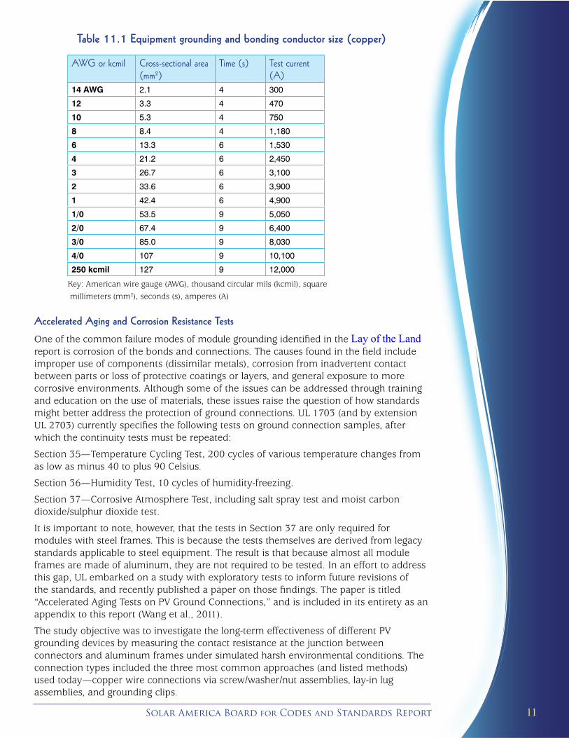
25.2.3 After completing the 25.2.2 tests, subject two of the three test samples of the grounding means to the current specified in Table 11.1 for the time specified in that table. The current shall be based on the largest size of wire for which the grounding means is marked. The third test sample shall be exposed to a current of 5,000 amps through the maximum allowable nonrenewable (i.e. single-use) fuse in accordance with 47.10. For both tests the grounding means shall not crack, break, or melt.
11Solar America Board for Codes and Standards Report
Table 11.1 Equipment grounding and bonding conductor size (copper)
AWG or kcmil Cross-sectional area (mm2)
Time (s) Test current (A)
14 AWG 2.1 4 300
12 3.3 4 470
10 5.3 4 750
8 8.4 4 1,180
6 13.3 6 1,530
4 21.2 6 2,450
3 26.7 6 3,100
2 33.6 6 3,900
1 42.4 6 4,900
1/0 53.5 9 5,050
2/0 67.4 9 6,400
3/0 85.0 9 8,030
4/0 107 9 10,100
250 kcmil 127 9 12,000
Key: American wire gauge (AWG), thousand circular mils (kcmil), square
millimeters (mm2), seconds (s), amperes (A)
Accelerated Aging and Corrosion Resistance Tests
One of the common failure modes of module grounding identified in the Lay of the Land report is corrosion of the bonds and connections. The causes found in the field include improper use of components (dissimilar metals), corrosion from inadvertent contact between parts or loss of protective coatings or layers, and general exposure to more corrosive environments. Although some of the issues can be addressed through training and education on the use of materials, these issues raise the question of how standards might better address the protection of ground connections. UL 1703 (and by extension UL 2703) currently specifies the following tests on ground connection samples, after which the continuity tests must be repeated:
Section 35—Temperature Cycling Test, 200 cycles of various temperature changes from as low as minus 40 to plus 90 Celsius.
Section 36—Humidity Test, 10 cycles of humidity-freezing.
Section 37—Corrosive Atmosphere Test, including salt spray test and moist carbon dioxide/sulphur dioxide test.
It is important to note, however, that the tests in Section 37 are only required for modules with steel frames. This is because the tests themselves are derived from legacy standards applicable to steel equipment. The result is that because almost all module frames are made of aluminum, they are not required to be tested. In an effort to address this gap, UL embarked on a study with exploratory tests to inform future revisions of the standards, and recently published a paper on those findings. The paper is titled “Accelerated Aging Tests on PV Ground Connections,” and is included in its entirety as an appendix to this report (Wang et al., 2011).
The study objective was to investigate the long-term effectiveness of different PV grounding devices by measuring the contact resistance at the junction between connectors and aluminum frames under simulated harsh environmental conditions. The connection types included the three most common approaches (and listed methods) used today—copper wire connections via screw/washer/nut assemblies, lay-in lug assemblies, and grounding clips.

12P Photovoltaic Module Grounding: Issues and Recommendations
Identical sample sets were installed and aged separately using:
• Damp heat aging according to IEC 61215, “Crystalline silicon terrestrial photovoltaic (PV) modules—Design qualification and type approval.” This consisted of 85⁰C ambient temperature and 85% relative humidity for 1,000 hours.
• Salt mist aging according to IEC 60068-2-11, “Basic Environmental Testing Procedures, Part 2: Tests-Test Ka: Salt Mist.” This standard compares resistance to deterioration from salt mist between materials of similar construction, and is used to evaluate the quality and the uniformity of protective coatings. The environment consists of continuous fine mist of aerated 3% NaCl solution buffered to a pH of 5.5.
Additionally, certain samples were cycled with current during the tests to simulate typical daily solar profiles. The contact resistance was measured before and after each test for comparison. The table below describes each of the sample types that were tested. The “compound” notation indicates samples that included anti-oxidation coatings on the connections.
Sample Groups and Configurations (from Accelerated Aging Tests on PV Grounding Connections [Wang et al., 2011])
Connectors Sample nos. Connector type & installation methods
A
1 (control) Attaching a tin-plated copper lay-in lug to aluminum frame with a stainless steel (SS) locknut penetrating the aluminum surface
2 (compound)
3 (current)
B
1 (control) Removing the anodization on the aluminum frame and then attaching tin-plated copper lay-in lug directly to it; an anti-oxidant compound was applied between the lug and aluminum surface
2 (compound)
3 (current)
C
1 (control)
Grounding copper wire to aluminum frame using SS thread-cutting screw and SS cup washer
2 (compound)
3 (current)
D
1 (control) Attaching a tin-plated lay-in lug to aluminum frame with a teeth washer laid between the lug and aluminum surface (teeth face towards the aluminum surface)
2 (compound)
3 (current)
E
1 (control)
Using a grounding clips assembly consisting of a slider, base, and SS thread-cutting screw
2 (compound)
3 (current)
Salient results include:
• In the damp-heat condition, the resistances for all connectors remained low (<0.05 ohm) and had almost no change over 20 weeks.
• In the salt mist condition, however, most samples corroded severely and failed in weeks, where failure was set at >10 ohms.
• Samples using the anti-oxidant coating lasted longer before failing.
• The lay-in lug with washer (D) and grounding clips (E) with compound lasted more than 20 weeks in the salt mist condition.

13Solar America Board for Codes and Standards Report
• Currentcyclingdidnothaveasignificantimpactonthesamplestestedundersalt mist conditions. Sample D appears to be an exception, but there is insufficient data to conclude that there is a meaningful difference with that method. Speculation is that the accelerated aging under salt mist condition was too severe (and fast-acting) to show the effects of current cycling.
• Proper torque on the connections improved the performance. Connections that were under-torqued failed five times sooner than those that used a torque wrench to achieve the manufacturer specifications. This result clearly underscores the importance of using torque wrenches in the field to ensure properly torqued connections, and of having the proper torque values plainly communicated to installers.
The UL aging paper was released recently and is still being evaluated. A thorough industry review will be important for determining if and how those tests should be applied in standards. Solar ABCs will publish an update of the industry response in the spring of 2012. In the meantime, we include some preliminary feedback here.
Initial recommendations include that there be additional review of the attachment methods by manufacturers of the grounding clips and lay-in lugs. For example, one lay-in lug manufacturer’s instructions recommend using a flat washer between any lock or star washer and the lug surface. This is presumably to prevent excessive penetration of the tin plating on the lug and exposure of the underlying copper to galvanic corrosion. A flat washer would also create a firmer surface relative to the soft copper lug and aluminum module surfaces, which can deform under the pressure of a lock washer (Wiles, 2011).
Other questions and suggestions regarding the specific configurations, parts, and scope of the tests include:
• requests for explicit information on the parts and components used in the tests to better understand and qualify the failures;
• suggestions for additional tests, expanded to include other available components that could exhibit different performance characteristics; and
• better characterization of the module anodization thickness, which can vary markedly and may have an impact on testing results.
A few stakeholders (manufacturers and other NRTLs) suggested that the tests were a welcome start and recommended the consideration of additional tests with a wider forum of participation for defining the scope of tests.
It is important to note that the UL aging paper did not state that the salt mist tests as defined by IEC 60068-2-11 should be incorporated into standardized tests for listing purposes. Although it is widely acknowledged that tests need to be more rigorous to help reduce corrosion issues, many in the industry have expressed concern about using a testing approach employing continuous exposure to salt mist. IEC 60068-2-11 and ASTM (formerly American Society for Testing and Materials, now ASTM International) B117 have both been cited and used in component tests, and both prescribe continuous salt mist exposure. The standards aren’t significantly different. In general, the IEC testing procedure is broader and the ASTM method is more specific and thorough, describing the parameters of the test and how to measure them in more detail. Some of the specific differences include:
• The IEC test procedure calls for no more than 0.1% sodium iodide whereas the ASTM standard states that halides including bromide, fluoride, and iodide make up no more than 0.1%.
• The IEC procedure suggests a water temperature of at least 35°C, whereas the ASTM test procedure suggests a water temperature of 46°C to 49°C to offset the cooling effect of expansion to atmospheric pressure during the atomization process.

14P Photovoltaic Module Grounding: Issues and Recommendations
• The IEC standard gives no guidelines for positioning the tested component, but states that its position in the test chamber is of prime importance. The ASTM standard recommends that the components be supported or suspended between 15° and 30° from the vertical and parallel to the principal direction of the flow of fog through the chamber.
The Lay of the Land report includes a more detailed discussion of issues specifically concerning the use of ASTM B117, which we repeat here for convenience:
SunPower in particular provided comments to the STP pointing out that the corrosion mechanisms induced by the B117 tests are known to often differ from those found in the field. Their argument is that the results cannot accurately provide a correlation between the accelerated tests and long-term performance in field conditions, and therefore the potential exists for the industry to chase the wrong problems. The B117 practice itself cautions against the use of the method to predict corrosion performance in the field, and SunPower cites corrosion experts from the auto and electronics industry who have expressed concerns about the use and interpretation of such tests. They stated that in general, the use of accelerated corrosion test procedures that have not demonstrated correlation with performance in natural environments for the materials and physical configurations in question is of limited value and must be interpreted with caution. Attempting to accelerate galvanic corrosion is particularly problematic. For example, the ASTM reference on corrosion tests and standards states “Accelerated testing to get a result in a shorter time period than would be possible naturally should be avoided whenever possible, because the mechanism of galvanic corrosion can change if the rate is altered significantly.” (Baboian, 2005).
Actual installations exist in a wide range of environments and these particular tests may only be truly pertinent for the more punishing marine environments. Coastal industrial areas, for example, may have combined high humidity and chemical content, and acid rain may be a contributing factor in areas with high rainfall.
A UL 1703 STP subcommittee has been formed to pursue this topic and develop a proposal for revisions, which will most likely be incorporated in UL 2703 as well. One promising development likely to inform these changes is a pending revision to IEC 61701 (Edition 2), “Salt mist corrosion testing of photovoltaic (PV) modules.” The revision departs from IEC 60068-2-11 and instead derives more from IEC 60068-2-52, which is widely used in the electronic component field. The tests also better reflect field conditions. For example, the modules are exposed to cycles of alternating salt fog and humidity rather than continuous salt fog. The subcommittee will most likely recommend that some variation of the testing defined in IEC 61701 be used to replace the existing contents of Section 37 in UL 1703. Solar ABCs will publish a brief follow-up report on this activity in the coming year.
“The UL aging paper wasreleased recently and is still being evaluated. ”

15Solar America Board for Codes and Standards Report
MODULE GROUNDING AND SAFETy UNDER FAULT CONDITIONS
This section focuses on background material to be used as the basis for module grounding and the design of safe systems. The section reviews basic concepts of the impact of electricity on the human body and by extension the potential danger to personnel presented by improperly grounded module frames. We then look at module frame fault scenarios. An analysis of these types of faults provides guidance for determining adequate conductivity of the grounding system and adequate performance of frame connections that carry fault current. Finally, we discuss systemic methods of module grounding and how well they address safety in the event of the faults.
ELECTrICITy AnD ThE hUmAn BoDy
There are several references on body resistance and the levels of current that cause harm to humans. IEC standard 60479-1 (IEC, 2005), for example, defines typical body impedances as a function of voltage, contact area, contact points, conditions (wet, dry) of skin, and percentiles of population.
Figure 1 shows the impedance as a function of voltage for low frequency AC (50/60 hertz [hz]), from hand-to-hand, under dry, wet, and saltwater wet conditions. The curves are representative of the 50th percentile of the population, meaning 50% of the population’s body impedance is at these or lower values.
Figure 1: Total Body Impedances for a Current Path of Hand-to-Hand for a Percentile Rank of 50% of the Population (50/60 Hz AC) (IEC, 2005)
Figure 2 shows a similar chart comparing the body impedances for DC and AC voltages, under dry conditions. DC resistances tend to be higher at lower voltages, but are similar to AC resistances. Below 200V, the DC resistance is higher due to the blocking effect of the skin capacitances.

16P Photovoltaic Module Grounding: Issues and Recommendations
The two charts together indicate that the dry, wet, and saltwater wet conditions of the AC case apply reasonably well to DC voltage conditions.
This chart is also representative of the 50th percentile rank of the population. Note that UL typically uses the more conservative 5th percentile values to address shock issues. Using the 5th percentile values for safety measures effectively means that 95% of the population is protected.
Figure 2: Total Body Impedances for a Current Path of Hand-to-Hand for a Percentile Rank of 50% of the
Population (AC vs. DC) (IEC, 2005)
The table below from IEC 60479-1 (IEC, 2005) shows the DC resistance values for 5%, 50%, and 95% of the population. The 50% values correspond to the chart in Figure 3, and the 5% values are those used by UL.
Total Body resistances for a Current Path hand-to-hand, DC, for Large Surface Areas of Contact in Dry Conditions
(from Table 10, IEC 60479-1 [IEC, 2005])
Touch voltage V Values for the total body resistance RT (ohm) that are not exceeded for
5% of the population 50% of the population 95% of the population
25 2,100 3,875 7,275
50 1,600 2,900 5,325
75 1,275 2,275 4,100
100 1,100 1,900 3,350
125 975 1,675 2,875
150 875 1,475 2,475
175 825 1,350 2,225
200 800 1,275 2,050
225 775 1,225 1,900
400 700 950 1,275
500 625 850 1,150

17Solar America Board for Codes and Standards Report
Touch voltage V Values for the total body resistance RT (ohm) that are not exceeded for
5% of the population 50% of the population 95% of the population
700 575 775 1,050
1,000 575 775 1,050
Asymptotic value 575 775 1,050
The various sources indicate that the body is somewhat more tolerant of DC than AC voltage shocks. IEC 60479-1 (IEC, 2005) states that harmful accidents with DC systems are much less frequent than would be expected given the proportional number of DC and AC systems that exist. This is in part due to the fact that it is easier to let go of DC than AC live parts, and “for shock durations longer than the period of the cardiac cycle, the threshold of ventricular fibrillation is considerably higher than for alternating current.”
Figure 3 shows time current zones of DC current and its impact on the body. Zones DC3 and DC4 are levels that are potentially harmful or fatal, whereas the Zones DC 1 and DC 2 have different levels of feel and reaction but generally do not cause physiological damage. The DC3 zone begins at curve “b” and above. Curves c1, c2, and c3 are representative of current magnitudes and durations at which the probabilities of ventricular fibrillation increase respectively for the population. Curves c2 and c3 represent 5% and 50% of the population. Values below the c1 curve are thought to be conservative for all humans.
Figure 3: DC Time-Current Curves and Zones Defining the Typical Impact on Human Beings (IEC, 2005)
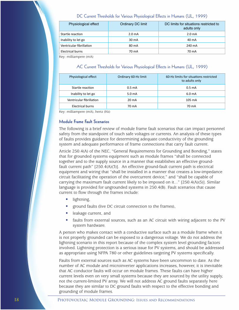
UL uses a specific set of tables from a 1999 Electric Power Research Institute report as the basis for current thresholds used in its safety standards (UL, 1999).
The two tables below show these DC and AC current limits as a function of the physiological effects caused in humans in general, and those restricted to adults only.
18P Photovoltaic Module Grounding: Issues and Recommendations
DC Current Thresholds for Various Physiological Effects in humans (UL, 1999)
Physiological effect Ordinary DC limit DC limits for situations restricted to adults only
Startle reaction 2.0 mA 2.0 mA
Inability to let go 30 mA 40 mA
Ventricular fibrillation 80 mA 240 mA
Electrical burns 70 mA 70 mAKey: milliampere (mA)
AC Current Thresholds for Various Physiological Effects in humans (UL, 1999)
Physiological effect Ordinary 60-Hz limit 60-Hz limits for situations restricted to adults only
Startle reaction 0.5 mA 0.5 mA
Inability to let go 5.0 mA 6.0 mA
Ventricular fibrillation 20 mA 105 mA
Electrical burns 70 mA 70 mAKey: milliampere (mA), hertz (Hz)
Module Frame Fault ScenariosThe following is a brief review of module frame fault scenarios that can impact personnel safety from the standpoint of touch safe voltages or currents. An analysis of these types of faults provides guidance for determining adequate conductivity of the grounding system and adequate performance of frame connections that carry fault current.
Article 250.4(A) of the NEC, “General Requirements for Grounding and Bonding,” states that for grounded systems equipment such as module frames “shall be connected together and to the supply source in a manner that establishes an effective ground-fault current path” [250.4(A)(3)]. An effective ground-fault current path is electrical equipment and wiring that “shall be installed in a manner that creates a low-impedance circuit facilitating the operation of the overcurrent device,” and “shall be capable of carrying the maximum fault current likely to be imposed on it...” [250.4(A)(5)]. Similar language is provided for ungrounded systems in 250.4(B). Fault scenarios that cause current to flow through the frames include:
• lightning,
• ground faults (live DC circuit connection to the frames),
• leakage current, and
• faults from external sources, such as an AC circuit with wiring adjacent to the PV system hardware.
A person who makes contact with a conductive surface such as a module frame when it is not properly grounded can be exposed to a dangerous voltage. We do not address the lightning scenario in this report because of the complex system level grounding factors involved. Lightning protection is a serious issue for PV systems, and should be addressed as appropriate using NFPA 780 or other guidelines targeting PV systems specifically.
Faults from external sources such as AC systems have been uncommon to date. As the number of AC module and microinverter applications increases, however, it is inevitable that AC conductor faults will occur on module frames. These faults can have higher current levels even on very small systems because they are sourced by the utility supply, not the current-limited PV array. We will not address AC ground faults separately here because they are similar to DC ground faults with respect to the effective bonding and grounding of module frames.

19Solar America Board for Codes and Standards Report
Presently the two module frame fault scenarios most likely to present a potential shock or safety hazard are the DC circuit ground fault and leakage current. The discussions here center around module frames, but these faults can also occur on other conductive surfaces that rely on the module frame for a conductive path to the ground circuit—an isolated mounting clip, for example.
Conductor Fault to Frame
On a grounded DC system, a short-circuit fault will occur if a damaged ungrounded string conductor is exposed and electrically connected to a module frame. For example, if the PV system has a negative-grounded circuit (the most common design in the United States today), a short of the positive conductor to a frame will create a direct connection between the array positive and negative circuit. Figure 4 shows a diagram of this ground fault example. As indicated by the red arrows in the figure, the path of the fault current is from the:
• exposed positive polarity conductor to the module frame,
• module frame to the ground circuit (equipment grounding conductor),
• equipment grounding conductor to the inverter ground bus,
• inverter ground bus to the inverter negative bus (location of negative to ground bond through the ground fault detector interrupter [GFDI]), and
• negative ground bus to the negative conductor of the faulted string.
As the figure shows, however, the fault current is not limited to the single faulted string. The entire array positive pole is grounded via this connection to the frame, so most of the fault current is backfed from the positive bus at the combiner box and the recombining fuse bridge feeding the inverter. These currents will flow through this fault connection until either the GFDI or the faulted string fuse operates.
+
CENTRAL INVERTER
GFDI
+
-
PARALLEL POSITIVE SOURCE CIRCUITS
PARALLEL NEGATIVESOURCE CIRCUITS
RECOMBINER OR INVERTER FUSED INPUT BRIDGE
-
STRING COMBINER BOX
EQUIPMENT GROUND
Fr
Ground fault on ungrounded conductor
MODULE FRAME
X
Figure 4: Representation of a DC Ground Fault to a Module Frame
Most systems installed in the United States today incorporate GFDI circuits in the inverter. Most of these GDFI circuits interrupt the fault current using fuses or other overcurrent protection devices (OCPD) ranging from 1A to 5A, depending on the size of the inverter. So for most arrays, a hard (or low impedance) fault between the positive pole circuit (conductor) and ground (module frame) will cause the GFDI to operate, isolate the fault, and stop fault current.

20P Photovoltaic Module Grounding: Issues and Recommendations
This fault condition would also typically cause the faulted string fuse to blow, due to the same (entire) array current circulating through that single fuse to the fault point. With string fuse ratings typically between 5A and 15A, the GFDI is likely to interrupt first. Systems without GFDI rely on the string fuse, which interrupts current from the rest of the array but does not stop the circulating fault current of the one faulted string.
A DC ground fault may not trigger the OCPD if the fault is a high-impedance or weak connection or if the irradiance is low. Any factor limiting the current in the fault circuit will prevent or delay OCPD operation, including resistance in the ground path from module frames to the ground circuit.
Leakage Current to Frame
Leakage current in grounded PV systems is an unavoidable phenomenon involving very small amounts of current “leaking” from the cells to the module frames, typically via the module glass. Assuming the frame is properly grounded, the leakage current travels from the frame to the ground circuit and returns via the grounded polarity conductor to the modules.
Under normal conditions, there is no safety hazard. The PV frame is maintained at ground potential by the NEC-required ground connection for accessible unenergized metal and therefore does not attain a hazardous touch voltage relative to other grounded metal or to earth. If the frame has a poor or discontinuous ground connection, however, the frame voltage relative to earth potential can be significant (especially on a high voltage PV array) and a person touching the frame can become the path for the leakage current. Again, under normal operating conditions, even this event would most likely not be dangerous. However, abnormal leakage currents to frame on a big system (for example, caused by aging or defective PV modules with broken glass or delamination, and made worse by wet conditions) could cause enough of a voltage potential and energy to injure or kill anyone who contacts the ungrounded PV module frame.
A “worst-case” scenario related to module frames occurs when a person is the only path for potentially high ground fault current. For example, if there was a conductor to frame fault (as described in the section above) and the frame had no ground connection, a person touching the frame would experience the same shock as if he touched the live wire.
If the module frame has a poor, high impedance ground connection, the person touching the frame becomes an alternate parallel path for ground current to flow. A spectrum of variables determines whether that person would be injured by electrical shock, including the:
• impedance in the frame-ground circuit (it must be high enough that there is insufficient fault current to operate the GFDI);
• size of the array (it must be large enough to maintain a dangerous voltage on the frame before and after the person touches it);
• resistance of the person’s body (as discussed earlier); and
• resistance between the body and the return path to ground, which can be through the earth or other grounded metal such as an adjacent PV module or mounting frame.
Overall, the strength of the power source determines the voltage and current characteristics when applied through a specific impedance, and the impedance of the equipment ground circuit determines how much of the fault current can be diverted through a person’s body. A deeper analysis of these phenomena using array simulation models such as PSPICE would be useful, but is beyond the scope of this study.

21Solar America Board for Codes and Standards Report
Implications of Frame Grounding Approach From a practical standpoint, the goal should be to determine the maximum allowable resistances in the equipment grounding circuit to keep voltage differences sufficiently low and fault current path capabilities sufficiently high. To address these questions, it is helpful to summarize three different module grounding scenarios and identify issues that need more attention.
Frames Bonded to Conductor or Structural Equipment Grounding Conductor
Module frames in a contiguous row are bonded to an equipment grounding conductor (ECG)—copper wire, for example—using standard methods (ground holes, nut/bolt assembly, or lay-in lug). Or, the module frames are bonded to an EGC equivalent, such as a mounting bar or tracker torque tube, using a tested (listed) method. In either case, the primary if not only ground current path is through the conductor. Parallel paths may exist via conductive mounting hardware, but personnel safety does not depend upon them.
Frames Bonded Directly or Indirectly to Other Module Frames With a Single Ground Circuit Path
In this case, module frames in a contiguous row are bonded sequentially to each other, via a clip or equivalent, so that the ground current path is primarily if not only through the frames themselves. Parallel paths may exist via conductive mounting hardware, but personnel safety does not depend upon them.
Frames Bonded Directly or Indirectly to Other Module Frames With Multiple Ground Circuit Paths
In this case, module frames in multiple contiguous rows are bonded to each other creating multiple intended paths, via the mounting structure or multiple clip connections. An example might be a rooftop system using multiple clips to secure modules to each other or to clamps that secure the modules to a metallic racking system. With so many connection points from module to module and other mounting hardware, the array is effectively a contiguous sheet with very low ground resistance paths.
Of these three scenarios, the second is of greatest concern or interest because of the number of frames and connections between the frames that are in the path of any array ground faults. If there are 30 contiguous modules connected together mechanically, each with 0.1 ohm connections to the next module (as permitted by UL 1703), there is now a 3 ohm ground path between the first module and an actual EGC. A person is not able to reach across such a great distance, but it is feasible that someone could be standing by a combiner box and a module that is electrically distant from that box. The impedance between the combiner box and the module might present a problem if the person touches both.
Elaborating on this example, consider the case of a high impedance fault that exists between a module frame and ground and causes 6A of current to flow through the module frames on the ground circuit. The 5A GFDI fuse in the inverter is “seeing” this current, but will not operate for some time. If the resistance of the module frame/connection path is 10 ohms, there will be a 60V difference between the combiner box enclosure and the module frame. A person touching both presents a 1,000 ohm parallel path for the ground current between the frame and the combiner box, therefore passing as much as 60 milliamperes (mA) through the body. While likely not fatal, this would be an unacceptable hazard.

22P Photovoltaic Module Grounding: Issues and Recommendations
To establish an example for minimum ground circuit resistance, assume a:
• designfaultcurrentof15A(15Athrougha5AOCPDwouldtripinlessthana minute),
• loworderbodyresistanceof1kohm,and
• maximumallowablefaultcurrentthroughthebodyof30mA.
In this example, the touch voltage would need to exceed 30mA*1kohm or 30V to cause 30mA through the body. This means the ground circuit resistance between two objects accessible to the person cannot exceed 2 ohms (30V/15A).
A maximum ground circuit resistance value clearly cannot be easily generalized, but one lesson to learn from these examples is the importance of minimizing the electrical distance between two physical objects accessible to a person. Using the grounding approaches as defined in the first and third scenarios will provide the greatest assurance by limiting the reliance on module frames and their connectors for a path of any distance.
Another way to evaluate the overall ground path resistance is to compare it to the resistance of EGCs as sized in the NEC:
Article 250.4(A) Grounded Systems(3) Bonding of Electrical Equipment. Normally non-current-carrying conductive materials enclosing electrical conductors or equipment, or forming part of such equipment, shall be connected together and to the electrical supply source in a manner that establishes an effective ground-fault current path.
(5) Effective Ground-Fault Current Path. Electrical equipment and wiring and other electrically conductive material likely to become energized shall be installed in a manner that creates a low-impedance circuit facilitating the operation of the overcurrent device or ground detector for high-impedance grounded systems. It shall be capable of safely carrying the maximum ground-fault current likely to be imposed on it from any point on the wiring system where a ground fault may occur to the electrical supply source. The earth shall not be considered as an effective ground-fault current path.
NEC Table 250.122 determines the minimum EGC sized for circuits protected by OCPDs. The smallest conductor in the table applies to 15A OCPDs and is a #14 AWG wire. If conservatively applied (maximum GFDIs are 5A OCPDs), the grounding circuit could be based on the equivalent resistance of the #14 gauge wire, which is 3 ohms per 1,000 feet.
UL is also exploring the issue of how to define listing criteria at the module level when unknown numbers of panels bonded electrically in series are possible. The industry should expect more information to come as Standards 1703 and 2703 are further developed.

23Solar America Board for Codes and Standards Report
Recommendations for Installations
The interim Lay of the Land report identified numerous causes of inadequate module ground connections. Failed connections were broadly defined as those no longer capable of reliably providing sufficient and appropriate electrical continuity between components. Many of the failure modes fall under the category of design or installation error, which can and should be avoided regardless of the status of listing standards.
Designers and installers therefore should minimize the avoidable problems by following these guidelines:
• Only install PV modules per the manufacturer’s installation instructions.
• Only use the grounding methods provided with the PV module or referenced in the module’s instruction manual. (Unfortunately, in a few cases grounding instructions have not been recently reviewed by the listing NRTL and do not comply with current UL 1703 grounding requirements. This is hopefully only a temporary problem. Designers and installers familiar with the standards should look for such discrepancies and alert module manufacturers when appropriate.)
• Prevent loosened connections by using proper split washers or equivalent means.
• Use torque wrenches to ensure bolted or screwed connections are not under- or over-torqued. Module frames are relatively thin and it is easy to over-torque and strip a connection. Under-torqued connections may not adequately pierce the anodization or other frame coating. Furthermore, the accelerated aging tests documented in this report demonstrated that under-torqued connections can accelerate corrosion significantly. Always follow equipment instructions for the proper torque values.
• Use care and caution working with and around the ground conductors or equivalent EGCs after bonding the module frame, to minimize stressing the connections during construction. It is not uncommon to see rough handling of modules and mounting hardware, particularly on larger systems.
• Take care to achieve the proper orientation and alignment when drilling into the frame or bolting a connection per the module manufacturer’s installation instructions.
• Take the time to ensure the washer/nut combination or assemblies are correctly specified for the module (in this case from the module installation manuals) to achieve a durably tight connection. “Minor” changes to the materials, size, thread-count, diameter, etc., can easily lead to failed connections on a systemic level.
o On a related note, John Wiles of New Mexico State University recommends that the industry move away from allowing mechanical fasteners to be part of the conductive path in the ground connection. Mechanical fasteners (usually stainless steel) are not generally used to carry electrical power except in devices that have been tested and listed for that use. Instead, the mechanical fasteners are used to bring the electrically conductive surfaces together. Yet many module installation manuals prescribe the use of the stainless steel flat washers as a barrier between an aluminum frame and other conducting body, making the stainless steel fasteners an integral part of the current conducting path. Wiles also suggests that the module manufacturers make their modules with a copper-compatible grounding lead or grounding terminal as one manufacturer did years ago. These subjects should be addressed further.
• Do not allow continual stressing of a connection post-installation by applying more tension on the ground wire or force on the assembly than it can reliably endure. An example is a ground cable pulled so tight that it compromises the assembly or the frame itself.

24P Photovoltaic Module Grounding: Issues and Recommendations
• Avoid repeated installation of self-drilling or thread-forming machine screws. Get it right the first time. Normal threaded fasteners are tested to ensure that repetitive use will not damage the threads (the CRD that UL issued for UL 1703 requires installing and removing threaded fasteners ten times). Self-drilling or thread-forming machine screws are not intended for repetitive use, however, and are likely to score or wear the existing threads.
• Ensure that components designed to pierce the module coatings, such as star washers or serrated screwheads are selected and installed properly. This extends to ensuring that the sharp edges of the washer face the correct direction (if it is not symmetrically designed), and that it is part of the turning assembly during tightening.
• Ensure the selection of materials for the bonded connection so that these do not cause corrosion. Direct copper and aluminum bonds (without a galvanically compatible surface barrier) are the most common dissimilar metal combination leading to destructive corrosion in PV systems.
• Limit the proximity of the dissimilar metals to each other, such as a copper ground wire running adjacent to and touching the module frames. Over time there can be corrosion when the equipment increases contact by exposure to water, soil, or other conductive debris elements. This corrosion may only be an aesthetic issue, but it is still good practice to limit this exposure where possible.
• In highly corrosive environments—close to seawater, for example—best practice may also include the use of a protective coating such as an anti-oxidant compound on the connection to extend the useful life of the bond. Even with these added measures, ongoing and preventative maintenance could also be required in these environments to keep the contact resistance low.
One proposal described in the Lay of the Land report was to simplify the list of allowed materials used for grounding devices and mounting means. This was an alternative to defining acceptable combinations as any whose combined electrochemical potential is less than 0.6V. While the specifics of these requirements and conditions are defined, we recommend this minimalist list. Grounding devices and mounting means shall be constructed of:
• copper or a copper alloy containing not less than 80% copper, which may be coated or plated to avoid galvanic corrosion;
• stainless steel containing a minimum of 16% chromium (Cr) or 5000 or 6000 series aluminum alloys; or
• carbon steel, which may be coated or plated to avoid corrosion.
We propose an explicit requirement that there be “no direct contact between different metals that may exhibit galvanic corrosion in atmospheric environments either between parts within the grounding device, or when the device is attached as specified to the accessible conductive part.” The acceptable combinations include any combination of:
• 5000 or 6000 series aluminum alloys and commercially pure aluminum,• stainless steel containing a minimum of 16% Cr,• nickel,• tin,• zinc, and• zinc-aluminum alloys.
These material combinations are galvanically compatible in almost all service environments. However, platings or coatings must be of sufficient thickness and quality to withstand the service environment for the service life in order to provide an effective buffer layer. Compliance of platings or coatings is unknown, so such combinations need to be verified through the UL 1703 or UL 467 test programs to confirm they will operate as intended.

25Solar America Board for Codes and Standards Report
REFERENCES
Baboian, R. (Robert) (2005). Corrosion tests and standards: application and interpretation. Second Edition (P. 239).
International Electrotechnical Commission (IEC). (July 13, 2005). Effects of current on human beings and livestock. Part 1: General aspects, Edition 4.0. IEC/TS 60479-1.
National Electrical Code (NEC). (2011). NEC 2011 handbook, NFPA-70, National Fire Protection Agency.
Underwriters Laboratories Inc. (UL) (October 1999). Personnel protection devices for specific applications. Electric Power Research Institute, Project 6850-02, Final Report.
UL. (March 15, 2002, including revisions through April 2008). UL standard for flat-plate photovoltaic modules and panels. UL 1703, Third Edition.
UL. (September 3, 2004). UL standard for grounding and bonding equipment. UL 467, Eighth Edition.
UL. (January 28, 2010). UL standard for inverters, converters, controllers and interconnection system equipment for use with distributed energy resources. UL 1741, Second Edition.
UL. (2011). UL standard for rack mounting systems and clamping devices for flat-plate photovoltaic modules and panels. UL 2703, First Edition.
Wang, E. (Ethan), Yen, K. (Kai-Hsiang), Wang, C. (Carl), Ji, L. (Liang), and Zgonena, T. (Timothy ). (June 2011). Underwriters Laboratories. “Accelerated aging tests on PV grounding connections.” Presented at the IEEE 37th Photovoltaic Specialist Conference.
Wiles, J. (John). (July 2011). New Mexico State University. Email correspondence.
RESOURCES
Dalziel, C. F. (Charles) (July 1956). “Effects of electric shock on man.” IRE Transactions in Medical Electronics. Vol. PGME-5 (pp. 44-62).
Mead, J. (John). (2008). “Grounding and bonding of large roof-mounted photovoltaic systems.” Presented at Intersolar Conference.
IEC. (January 1, 1981). Basic environmental testing procedures. Part 2: Tests-Test Ka: Salt Mist.
IEC 61215. (October 2005). Crystalline Silicon terrestrial photovoltaic (PV) modules—design qualification and type approval. Edition 2.
Institute of Electrical and Electronics Engineers (IEEE). IEEE recommended practice for grounding of industrial and commercial power systems. IEEE Standard 142-2007.
National Fire Protection Association. (2008). Standard for the installation of lightning protection systems.

26P Photovoltaic Module Grounding: Issues and Recommendations
Appendix A: Accelerated Aging Tests on PV Grounding Connections
Presented at the IEEE 37th Photovoltaic Specialist Conference, June 2011
Accelerated Aging Tests on PV Grounding Connections
Ethan Wang1, Kai-Hsiang Yen1 and Carl Wang1, Liang Ji2, Timothy Zgonena2 1Underwriters Laboratories Taiwan Co., Ltd.
2Underwriters Laboratories Inc. Abstract: As many contemporary Photovoltaic (PV) Power systems being installed are designed to produce significant amount of electricity and claimed to operate for 25 years or more, appropriate grounding on PV modules to reduce or eliminate shock and fire haz-ards becomes a critical issue under high electricity output and long-term use. Although some PV manufacturers have provided technical bulletins to suggest grounding products and methods, not all of them have been carefully evaluated and reviewed by the certifica-tion/listing laboratories. In this paper, different types of PV grounding connectors were collected, installed and put into accelerated environmental test chambers. The effects of current cycling, assembly force, anti-oxidation coating application on grounding reliability were evaluated. The grounding failure modes and mechanisms are also discussed in this paper.
Keywords: PV grounding, electrical shock, accelerated aging, salt mist, galvanic corrosion, dissimilar metal
InTroDUCTIon Photovoltaic (PV) power systems being installed today are normally designed to produce significant amounts of electricity over an expected operating life of more than 25 years. The high electrical output and long-term reliable performance necessitate robust grounding systems for PV systems to minimize accidental electric shock and fire hazards.
In late 2007, UL issued an Interpretation of UL 1703 on the topic of module field grounding. The Interpretation clarified that the module instruction manual must specify the grounding methods and materials to be used for external field-made grounding connections. These methods and materials are evaluated as part of the module Listing process and will apply to all existing Listed modules and their instructions as they come up for review. [1].
A good connection between the grounding hardware and the module frame is essential for a grounding system to function properly. Typically PV manufacturers use copper-alloy for electrical connections and aluminum-alloy for the module frames. The anodization on the aluminum-alloy surfaces is able to provide an oxidized layer to minimize further corrosion of the frames. However, while the anodization of the aluminum-alloy surfaces creates an oxidized layer that minimizes frame corrosion, it also generates a high electrical resistance reducing grounding effectiveness. To overcome this design issue, the grounding hardware must penetrate through the anodization layer to create a direct electric connection. This is normally achieved by one of the following approaches: (1) Installing a self-tapping or self-drilling fastener through the frame, (2) using a stainless steel star (toothed) washer held against the frame by a bolt or nut, or (3) attaching a Listed lug (see figure 1) to the marked grounding points after appropriate surface preparation has been accomplished. [2] [3]
The differences in these grounding approaches may result in significant performance dif-ferences over the course of the product service life. Therefore further study is needed to address the long-term effect and reliability of these different grounding installations.

27Solar America Board for Codes and Standards Report
Figure 1 Lay-in lug Listed for direct burial (DB) and outdoor use
oBJECTIVE
The objective of this study is to investigate the long-term effectiveness of different PV grounding devices under simulated harsh environmental conditions. By measuring the contact resistance at the junction between connectors and aluminum frames, this scope of this study includes examining the following grounding techniques:
• Attaching lay-in lug to aluminum frame with a lock-nut penetrating the aluminum surface. • Removing anodization on the aluminum frame and then attaching lay-in lug directly to it. An anti-oxidant compound was applied between the lug and aluminum surface. • Grounding copper wire to aluminum frame using thread-cutting screw and cup washer.• Attaching lay-in lug to aluminum frame with a teeth washer laid between the lug and aluminum surface • Using grounding clips assembly consists of a slider, base, and thread-cutting screw.
In order to understand the possible corrosion effect caused by current, this study also com-pared the effectiveness of grounding technique with and without current.
The connectors, copper conductors, and anti-oxidant compound used in this study were all commercially available varieties obtained from different manufacturers. Manufacturers’ names are omitted from this paper since the intention of this study was not to compare specific manufacturer’s products.
TEST DESIGn
Different types of connectors were installed according to the instructions provided by the manufacturers, including the aluminum surface preparation, applying anti-oxidation coat-ing and the torque requirements. A DC power supply with current and voltage limiting functions was used for current cycling. As shown in Table 1, different groups of connectors from different manufacturers were put in series and each group has 3 samples labeled as Sample No. ‘1’ (control sample), ‘2’ (with anti-oxidation compound) and ‘3’(with current cycling) for comparison purpose. The aluminum frames were cut to the length of 10cm and identical pairs of connectors were installed at the frames. With this set-up, supplied current can flow in to one connector and out from the other.
Identical sample sets were installed and aged separately under the following two condi-tions: 1. Continuous salt mist spray, consisting of a fine mist of aerated 3% NaCl solution
buffer to a pH of 5.5. [4] 2. 85oC ambient temperature and 85% relative humidity. [5]

28P Photovoltaic Module Grounding: Issues and Recommendations
This was intended to produce conditions in which connectors that are susceptible to corrosion will show increased contact resistance over time. A 5 amps electrical current was cycled on and off on certain samples to simulate solar day current flow variations. For the resistance measurement, all contact resistances were measured at room temperature us-ing a micro-ohm meter from a terminal block placed out of the chambers. Copper conduc-tor wires were connected and fixed at the block as shown in Figure 2.
Table 1 Sample groups and configurations
Connectors Sample nos. Connector type & Installation methods 1 (control) Attaching a tin-plated copper lay-in lug to aluminum frame with a SS
lock-nut penetrating the aluminum surface. A 2 (compound)
3 (current)
1(control) Removing the anodization on the aluminum frame and then attaching tin-plated copper lay-in lug directly to it. An anti-oxidant
compound was applied between the lug and aluminum surface. (B-2 is the NEC suggested structure)
2 (compound)
B
3 (current)
1(control) Grounding copper wire to aluminum frame using SS thread-cutting screw and SS cup washer. C 2 (compound)
3 (current)
1(control) Attaching a tin-plated lay-in lug to aluminum frame with a teeth washer laid between the lug and aluminum surface (Teeth face
towards the Al surface) D
2 (compound)
3 (current)
1(control) Using grounding clips assembly consists of a slider, base, and SS thread-cutting screw. E 2 (compound)
3 (current)
Figure 2 Sample layout for the corrosion cycling

29Solar America Board for Codes and Standards Report
TEST RESULTS A. Damp heat Aging
Connector groups C, D and E were selected for damp heat aging study. The sample connectors were jointed together in series and subjected to continuous damp heat aging at 85oC ambient temperature and 85% relative humidity. The resistances of all connectors were measured every week at the same temperature level. Data (Figure. 3) shows that the resistances for all connectors remained in low level (<0.05Ω) and had almost no change over 20 weeks, which indicated that the connectors were still in good condition and mak-ing consistent connection. A resistance pulse at the 2nd week was found due to the abnor-mality of the ohmmeter. The meter got back to normal after that week. The experiment was terminated at the 21st week, as it’s believed that in short-term, continuous damp heat aging would not have any effects on the grounding integrity.
Figure 3 Resistance measurements for group C, D and E connectors under damp heat aging
B. Salt mist Aging Comparing to damp heat, salt mist condition was a much more severe atmosphere
for the grounding connectors. All of the connectors (group A, B, C, D and E) were aged under salt mist condition and the resistances were measured on every individual weekly until it is failed (defined as >10Ω). The resistance measurements data for No.1, No.2 and No.3 connectors are shown in Figure 4 to 6. And Figure 7 shows the failure time data of all connectors. As the figures show, some connectors became unstable and failed in a couple of weeks while some of the others had survived for more than 20 week. According to the data, group D connectors performed the best among all connectors.
Figure 4 Resistance change for all No.1 connectors under salt mist aging

30P Photovoltaic Module Grounding: Issues and Recommendations
Figure 6 Resistance change for all No.3 connectors under salt mist aging
Figure 7 Failure time analysis for all connectors under salt mist aging
Figure 5 Resistance change for all No.2 connectors under salt mist aging

31Solar America Board for Codes and Standards Report
Discussion
A. Conducting Paths Although there are different grounding connectors from different manufacturers, there are mainly three conducting paths for all grounding connections. The first one uses the teeth washer or lock nut as a conducting part; the second one uses the grounding lug itself as a conducting part and the last one uses the self-taping screw. Below are the diagrams of the conducting paths:
1.) Leakage Current→Aluminum Frame→Lock nut→Machine Screw→Flat washer→Lug→Copper Wire→Ground

32P Photovoltaic Module Grounding: Issues and Recommendations
B. Anti-oxidant Compound Application
Anti-oxidant compound we used in the research is UL Listed and recommended for all volt-ages and consists of non-petroleum base vehicle in which zinc particles are suspended. The compound was applied to the No.2 samples in all groups (A-2, B-2, C-2, D-2 and E-2). It was applied on the conductive surfaces of the connector components such as screw threads, copper wire, grounding lugs and the aluminum surface. The data in Figure 5 shows that the samples with anti-oxidant compound applied survived longer than the samples without it.
C. Current Cycling TestThe reason for conducting current cycling was to simulate solar day current flow variations and encourage corrosions at the connectors. For the test, a 5 Amps electric current was cy-cled on and off on No.3 connectors (A-3, B-3, C-3, D-3 and E-3). Theoretically, connectors and aluminum have different natural potentials in salt mist condition, an electric current will flow from the anode metal to the cathode, which will increases the corrosion on the anode. There-fore, supplying an external current on the connectors and aluminum frame would somehow influence the corrosion rate. From the data however, no significant change on corrosion rate was observed between the samples with and without current cycling. This is possibly due to the accelerated aging under salt mist condition was too severe for the connectors and the connectors failed too soon to show the effects of current cycling.
D. Installation Torque requirements The manufacturers should specify, in the module installation manual, the grounding meth-ods including torque requirements that must be used to establish grounding connections. For example, for the connectors use teeth washer as a part of the conducting path would ask the installers to tighten the mounting screw to a certain force level to ensure that the teeth fully embeds in the aluminum frame surface. In this research, connector D was picked for the comparison study. D-1 to D-3 connectors were torqued to the specified value with a torque wrench; while identical connectors D’-1 to D’-3 were assembled using a regular wrench and the force was way below the torque requirement. Figure 8 shows that group D’ connectors failed 5 times sooner than group D. This indicates that sample assembly force has great effects on connector failure time.
Figure 8 Failure time comparisons for connector D following torque requirements and not (D’)
E. Failure mechanism The grounding connectors of all groups showed a considerable amount of surface corro-sion after salt mist aging, and a build-up of white oxidation on the aluminum frames (Fig-ure 9 and 10). The white oxidations were collected and tested under EDX. With oxygen and metal peaks detected, it is proved that the white powders were metal oxides (Figure 11). The metal oxides are always non-conductive and act as an insulating layer, which block and destroy the grounding connections. On some of the lug connectors, the tin plat-ing had flaked off the surface and the inner copper had exposed. This could enhance the galvanic corrosion to occur as the tin-removed copper lugs were hardly pressed against the aluminum frames which creates a galvanic corrosion environment. Other forms of corrosions such as crevice corrosion and pitting corrosion were also observed.

33Solar America Board for Codes and Standards Report
The connectors or lugs created gaps and crevices and the differential aeration between the crevice and the external surface gave the crevice an anodic character and the exter-nal surface a cathodic character that prompted the crevice corrosion. Pitting corrosion includes local breakdown of protective passive film and always involves presence of chlo-ride ions [6].
Figure 9 Build-up of white oxidations on the
aluminum frame (screw sample)
Figure 10 Build-up of white oxidations on the
aluminum frame (lug sample)
Figure 11 EDX measurements for the white
oxidation on the aluminum frames

34P Photovoltaic Module Grounding: Issues and Recommendations
Summary and Conclusion
The reliability of different PV grounding connectors was compared by conducting acceler-ated aging under corrosive environmental conditions. The testing consisted of continuous damp heat and salt mist environmental exposure, in conjunction with periodical electrical current cycling. The connectors were evaluated by comparing the change in resistance of the test samples as the testing progressed. The results show that most of the samples were severely corroded and failed within weeks under the salt mist condition, while identi-cal samples in the damp heat chamber were still in good condition. The presence of ions (Na+, Cl-, etc) in salt water had a much greater effect on the rate at which metals corrode than just in heat and high humidity. The uses of anti-oxidant coating and connector assem-bly force also have effects on grounding integrity. With regard to the failure mechanism, different forms of corrosion - including galvanic corrosion, pitting corrosion, and crevice corrosion - were observed during the aging tests. Evidence showed that the insulating metal oxide formed during the corrosion broke the electrical connections and failed the grounding system.
ACKNOWLEDGMENT
This Research was performed at the Plastic Industry Development Center (PIDC) and sup-ported by the UL’s Advanced Energy Safety R&D Center Project (AESC), Multinational In-novative R&D Centers In Taiwan Program, Taiwan Ministry of Economic Affairs (MOEA) and Solar ABCs.
REFERENCE
[1] John Wiles, “Are we grounded yet”, IAEI NEWS, September-October 2008.
[2] BP Solar, “Grounding Methods for BP Solar Universal Framed Modules”, September 28, 2006.
[3] John Wiles, “Photovolatic Power Systems And the 2005 National Electrical Code: Suggested Practices”, March 2007.
[4] International Electrotechnical Commission, Basic Environmental Testing Procedures, Part 2: Tests-Test Ka: Salt Mist” IEC 60068-2-11.
[5] International Electrotechnical Commission, “Crystalline Silicon terrestrial photovoltaic (PV) modules- Design qualification and type approval”, IEC 61215.
[6] Pierre R. Roberge, “Corrosion Engineering: principle and practice” McGraw-Hill, 2008.

35Solar America Board for Codes and Standards Report
ACRONyMS A ampere
AC alternating current
AhJ authority having jurisdiction
AnSI American National Standards Institute
ASTm Formerly American Society for Testing and Materials, now ASTM International
AWEA American Wind Energy Association
AWG American wire gauge
Cr chromium
CrD certification requirements decision
DC direct current
EGC equipment grounding conductor
GFDI ground fault detector interrupter
hz hertz
IEC International Electrotechnical Commission
IECEE IEC System of Conformity Assessment Schemes for Electrotechnical Equipment and Components
IEEE Institute of Electrical and Electronics Engineers
kcmil 1,000 circular mils
mA milliampere
nEC National Electrical Code
nFPA National Fire Protection Association
nrTL Nationally Recognized Testing Laboratory
oCPD overcurrent protection device
PV photovoltaic
SS stainless steel
STC standard test conditions
STP Standards Technical Panel
UL Underwriters Laboratories

Solar America Board for Codes and Standardswww.solarabcs.org