bethlehem wire rope
DESCRIPTION
Wirerope Works, Inc. (WW) manufactures Bethlehem Wire Rope® products in a wide varietyof constructions, cores and steel grades. This catalog contains general information on wirerope constructions emphasizing the most common applications, based upon new, unused wirerope. Abuse or failure to exercise proper care and maintenance can significantly alter a wirerope’s characteristics, particularly the breaking strength.TRANSCRIPT


Wire rope products will break if abused, misused or overused. Consult industry recommendations and ASME Standards before using. Wirerope Works, Inc. warrants all Bethlehem Wire Rope® and Strand products. However, any warranty, expressed or implied as to quality, performance or fitness for use of wire rope products is always premised on the condition that the published breaking strengths apply only to new, unused rope, that the mechanical equipment on which such products are used is properly designed and maintained, that such products are properly stored, handled, used and maintained, and properly inspected on a regular basis during the period of use. Wirerope Works, Inc. expressly prohibits the resale of worn, previously owned and used Bethlehem Wire Rope and Strand products. Immediately following removal from service, all wire rope products are to be properly disposed of in accordance with applicable municipal, state, and federal guidelines. Manufacturer shall not be liable for consequential or incidental damages or secondary charges including but not limited to personal injury, labor costs, and a loss of profits resulting from the use of worn, previously owned and used products. Manufacturer shall not be liable for consequential or incidental damages or secondary charges including but not limited to personal injury, labor costs, a loss of profits resulting from the use of said products or from said products being incorporated in or becoming a component of any product. Bethlehem Wire Rope and the Bethlehem Wire Rope reel logo are registered trademarks of Wirerope Works, Inc. Form-set and Lift-Pac are trademarks of Wirerope Works, Inc.Wirerope Works, Inc. © 2007
Wire Rope SelectionWire Rope Construction ..................... 3Wire Rope Finish ................................ 3Wire Grade ........................................ 3Wire Rope Lay ................................... 3Preformed Wire Rope ......................... 4Wire Rope Core .................................. 5Wire Rope Lubrication ........................ 5The Modified X-chart .......................... 5Rope Substitution ............................... 5Suggested Wire RopeConstructions ..................................... 6
Standard Wire Rope6x7 Class ........................................... 96x19 Class106x37 Class ....................................... 10Alternate Lay Wire Rope .................. 12
Rotation-Resistant RopesSafety Design Factors ....................... 13Handling and Installation ................. 138x19 Class ....................................... 1419x7 ................................................ 14SFP 19 ............................................. 15SFP 35 ............................................. 15
Specialized Wire RopeGeneral Information ......................... 166-PAC ............................................... 178-PAC ............................................... 18Super-PAC ........................................ 19 Triple-PAC ......................................... 20 BXL .................................................. 21 Flattened Strand .............................. 22Roepac Compacted .......................... 23Oil Field and Natural Gas DrillingProducts .......................................... 24
Handling & InstallationMeasuring Rope Diameter ................ 26Unreeling and Uncoiling .................. 26Kinks ............................................... 26Drum Winding ................................. 26Wire Rope Clips ............................... 27Seizing Wire Rope ............................ 28Installation ....................................... 28Standard Operating Practices ........... 30
Wire Rope InspectionBasic Guidelines ............................... 31Inspection Guidelines for Specialized Wire Rope ...................... 32Drums and Sheaves .......................... 34Broken Wires In Wire Rope .............. 35Troubleshooting Checklist ................ 36
Technical InformationWW Specifications ........................... 37WW Markers .................................... 37Wire Rope Tolerances ....................... 37Rope Strength Design Factors .......... 37Physical Properties ........................... 38Effect Of Sheave Size........................ 38Block Twisting .................................. 38
Wire Rope SlingsBasic Hitches .................................... 40D/d Ratios ........................................ 40Sling Eye Designs ..............................40Effect Of Angles On Sling Capacities .40Wire Rope Sling Inspection ...............41Recommended Operating Practices ...41Standard Products LIst .......................43
Table Of Contents
Wirerope Works, Inc. (WW) manufactures Bethlehem Wire Rope® products in a wide variety of constructions, cores and steel grades. This catalog contains general information on wire rope constructions emphasizing the most common applications, based upon new, unused wire rope. Abuse or failure to exercise proper care and maintenance can significantly alter a wire rope’s characteristics, particularly the breaking strength. The technical data contained herein is based on accepted engineering practices and, where applicable, is in accordance with Occupation Safety and Health Administration standards. In use, this data should be supplemented by the application of the professional judgement of qualified engineering personnel. If your specific wire rope needs or requirements are not shown in this catalog, please consult WW’s sales or engineering department for technical information and recommenda-tions.
Wire rope products will break if abused, misused or overused. Consult industry recommendations and appropriate Stan-dards before using. Wirerope Works, Inc. warrants all Bethlehem Wire Rope® and Strand products. However, any warranty, expressed or implied as to quality, performance or fitness for use of wire rope products is always premised on the condition that the published breaking strengths apply only to new, unused rope, that the mechanical equipment on which such prod-ucts are used is properly designed and maintained, that such products are properly stored, handled, used and maintained, and properly inspected on a regular basis during the period of use. Wirerope Works, Inc. expressly prohibits the resale of worn, previously owned and used Bethlehem Wire Rope and Strand products. Immediately following removal from service, all wire rope products are to be properly disposed of in accordance with applicable municipal, state, and federal guidelines. Manufacturer shall not be liable for consequential or incidental damages or secondary charges including but not limited to personal injury, labor costs, and a loss of profits resulting from the use of worn, previously owned and used products. Manufacturer shall not be liable for consequential or incidental damages or secondary charges including but not limited to personal injury, labor costs, a loss of profits resulting from the use of said products or from said products being incorporated in or becoming a component of any product.
Bethlehem Wire Rope, the Bethlehem Wire Rope reel logo and Super B are registered trademarks of Wirerope Works, Inc. Form-set, Purple, Purple Plus, Royal Purple, Royal Purple Plus, SFP 19, 36DD, 6-PAC, 6-PAC RV, TRIPLE-PAC, BXL, SUPER-PAC, SKYBRITE, Roepac, Herringbone, En-Core, Bethpac, Maxi-Core, Phoenix, Z-nodes, wire rope colored purple and wire rope colored pink are trademarks of Wirerope Works, Inc.
Wirerope Works, Inc. © 1997, 2000, 2003, 2005, 2007, 2010 2.5M072010
Committed to the Consumer We continue to support our custom-ers by offering supply contracts and field evaluations of rope performance. We work with our customers to ensure maximum return of the investments made in equip-ment. Committed to Quality WW is certified to ISO 9001:2008 and API 9A by the American Petroleum Insti-tute (API). We are also certified by the American Bureau of Shipping (ABS) and Lloyd’s of London.
Committed to Service We service the industry with a large warehouse network, while developing additional outlets for our products, e.g., distributors. In addition, we continue to train and educate consumers in the use and application of wire ropes.
Owned by Americans. Made by Americans.
Wirerope Works, Inc. (WW)
manufactures Bethlehem Wire
Rope® to meet the exacting
demands of modern lifting
practices. The key to the success
of Bethlehem Wire Rope is the
total commitment WW makes
to the lifting industry.

3
Wire Rope Selection
Three Components of Wire Rope
Wire rope is a machine composed of a number of precise, moving parts, designed and manufactured to bear a very definite relation to one another. In fact, some wire ropes contain more moving parts than many complicated mechanisms. For example, a 6-strand rope with 49-wire strands laid around an independent wire rope core con-tains a total of 343 individual wires. All of these wires must work together and move with respect to one another if the rope is to have the flexibility necessary for successful operation. Wire rope is composed of wires, strands and a core. The basic unit of wire rope is wire, which is carefully processed and drawn from selected grades of steel to predetermined physi-cal properties and sizes. A prede-termined number of finished wires
is then helically laid together in a uniform geometric pattern to form a strand. This process must be per-formed with precision and exactness to form a strand of correct size and characteristics. The required number of suitably fabricated strands are laid symmetrically with a definite length of lay around a core, forming the finished wire rope. All Bethlehem Wire Rope products are manufactured at WW's fa-cility in Williamsport, Pennsylvania.
Wire Rope Construction Wire rope is identified by its con-struction, or the number of strands per rope, and number of wires in each strand. For example, the construction 6x25 denotes a 6-strand rope, with each strand having 25 wires. Con-structions having similar weights and breaking strengths are grouped into wire rope classifications, such as the 6x19 and 6x37 Classes.
Wire Rope Finish The term bright refers to a wire rope manufactured with no protective coating or finish other than lubricant. Some applications do require more corrosion protection than lubricant can provide. In these instances, a galvanized finish is provided. Consult with WW’s engineering department for more information on galvanized wire rope.
Wire Grade Purple grade wire (improved plow steel) is a strong, tough, durable steel that combines great strength with high resistance to fatigue. Its minimum tensile strength varies from 223 to 258 ksi, depending upon wire diameter. Purple Plus is WW’s trade name for Extra Improved Plow (EIP) steel. Once a specialty grade, Purple Plus is now WW’s grade for all standard wire rope. Minimum tensile strength varies from
245 to 284 ksi, depending upon wire diameter. Royal Purple, or Extra Extra Improved Plow (EEIP) steel, is a grade used where a high breaking strength is required. This grade typically pro-vides a breaking strength a minimum of 10% higher than Purple Plus and is found primarily as a standard grade for specialized wire rope. However, Royal Purple is available for standard wire ropes upon request. Developed by WW for the federal government, Royal Purple Plus is the highest strength grade available to Bethlehem Wire Rope customers. Royal Purple Plus provides a breaking strength 35% higher than Purple Plus, and is available in WW’s TRIPLE-PAC hoist rope. It is the grade of wire which deter-mines the nominal breaking strength for each diameter and construction. Note, the acceptance strength listed in the various tables for Bethlehem Wire Rope products is 2-1/2% below the nominal strengths listed. Other grades are available to meet specific requirements. Some grades are covered by wire rope standards while others may be specially tailored. Con-sult WW’s engineering department for further information.
Wire Rope Lay The helix or spiral of the wires and strands in a rope is called the lay. Regular lay denotes rope in which the wires are twisted in one direc-tion, and the strands in the opposite direction to form the rope. The wires appear to run roughly parallel to the center line of the rope. Due to the difference in direction between the wires and strand, regular lay ropes are less likely to untwist or kink. Regular lay ropes are also less subject to failure from crushing and distortion because of the shorter length of exposed outer wires.

Wire Rope Selection
4
Lang lay is the opposite; the wires and strands spiral in the same direc-tion and appear to run at a diagonal to the center line of the rope. Due to the longer length of exposed outer wires, Lang lay ropes have greater flexibility and abrasion resistance than do regu-lar lay ropes. Greater care, however, must be exercised in handling and spooling Lang lay ropes. These ropes are more likely to twist, kink and crush than regular lay ropes. Right or left lay refers to the direction in which the strands rotate around the wire rope. If the strands rotate around the rope in a clockwise direction (as the threads do in a right hand bolt), the rope is said to be right lay. When the strands rotate in a coun-terclockwise direction (as the threads do in a left hand bolt), the rope is left lay. Right regular lay is furnished for all rope applications unless otherwise specified. When a lay-length is used as a unit of measure, it refers to the linear distance a single strand extends in making one complete turn around the rope. Lay-length is measured in a straight line parallel to the center line of the rope, not by following the path of the strand. The appropriate time to replace a wire rope in service is frequently determined by counting the number of broken wires in the length of one rope lay.
Preformed Wire Rope Form-set is WW's trade name for preformed wire rope. Form-set means that the wires and strands have been preset during manufacture into the permanent helical form they take in the completed rope. Unless otherwise specified,
Bethlehem Wire Rope products are furnished Form-set. Preformed wire rope has definite characteristics which are advanta-geous on most wire rope applications. Preforming greatly reduces internal stresses, eases rope handling, and gives more equal distribution of load on the wires and strands. Preformed
rope runs smoother and spools more uniformly on a drum than non-pre-formed, has greater flexibility and gives longer service life in bending. Preformed wires tend to remain in position after breaking. This reduces the tendency for them to protrude and damage adjacent wires. Because the wires do not protrude, we strongly sug-gest greater care and more thorough inspection to detect broken wires in a Form-set rope.

Wire Rope Selection
5
Wire Rope Core Most wire ropes are supplied with either a fiber or steel core. The core is the foundation ot a wire rope. Its primary function is to support the wire strands of the rope, maintaining them in their correct relative positions during the operating life of the rope. Fiber cores are ropes made from fibers formed into yarns, then into strands and finally into the finished core form. There are two general types of fiber: natural vegetable material, such as sisal, and synthetic filaments, such as polypropylene. Steel cores may be an indepen-dent wire rope (IWRC) or, in the case of small diameter ropes and some ro-tation-resistant ropes, a wire strand core (WSC). These steel cores provide more support than fiber cores to the outer strands during the rope’s oper-ating life. Steel cores resist crushing, are more resistant to heat, reduce the amount of stretch, and increase the strength of the rope.
Wire Rope Lubrication During the manufacture of Beth-lehem Wire Rope products, WW applies heated lubricant to individual wires during the stranding operation. Upon
customer request, additional lubricant may be applied during the closing operation as well. WW utilizes two standard lu-bricants during the manufacture of general purpose ropes. WW’s N-lube is a petrolatum-based lubricantused primarily in the manufacture of standard wire rope. This type of lubricant prevents rust and corrosion and lubricates against internal wear. W-lube, the standard lubricant used for specialty wire rope, is an asphaltic-based lubricant and rust preventative compound with a large percentage of water-displacing addi-tives and corrosion inhibitors. W-lube is ideal for offshore and land cranes, and logging winch lines.
The Modified X-chart Two factors governing most de-cisions in selecting wire rope are abrasion resistance and resistance to bending fatigue. A graphic pre-sentation of the balance between these properties has traditionally been given by means of the X-chart. However, new designs of wire rope, such as 6-Pac and Triple-Pac, do not follow the X-chart model as they are designed to provide both abrasion
resistance and resistance to bending fatigue. WW, therefore, developed the Modified X-chart. To read the Modified X-chart, the position of each rope construction must be considered in relation to both the X and Y axes, or Abrasion Resistance and Resistance to Bending Fatigue, respectively. For example, the construction 6x41 (6x49) is in the upper left quadrant, ranking high on the bending fatigue scale. However, its position in abrasion resistance is very low. Therefore, it can be said that a 6x41 (6x49) construction offers ex-cellent resistance to bending fatigue, but poor resistance to abrasion. At the other end of the spectrum is a 6x7 construction, located in the lower right hand corner of the chart. A 6x7 offers excellent abrasion resistance, but very poor resistance to bending fatigue.
Rope Substitution Many equipment manufacturers have established standard or “speci-fied” wire ropes for their products. Rope substitution is acceptable provided the end user follow the basic design specifications established by the equipment manufacturer: •Alwaysusethespecified rope diameter. • Ensurethatthebreaking strength of the substitute rope meets or exceeds that of the rope specified. • Alwayssubstitutearope with the same basic characteristics, such as rotation resistance. ASME B30.5-1995 Addenda 5-1.7.2(a) states: The ropes shall be of a construction recommended by the rope or crane manufacturer or person qualified for that service.
High
Low
Resistance to B
ending Fatigue
➔➔➔➔➔➔➔➔➔➔➔➔➔➔➔➔
■ 6x41 (6x49)
■6x36
■6x31
■ 6x25 ■ 6x27 FlatStrand
■6x21
■ 6x19
■Super-Pac ■ 6x7
Low➔➔➔➔➔➔➔➔➔➔➔➔➔➔➔➔➔➔➔➔➔➔➔High Abrasion Resistance
■ 8-Pac■ Triple-Pac
■6-Pac

6
Suggested Wire Rope Constructions
APPLICATION GENERAL CONDITIONS SEVERE CONDITIONS
CRANES
DROP BALLS Load Lines 6x25 RR IWRC 6-Pac
GANTRY CRANES Main Hoist 6x25 RR IWRC; 6x36 Class RR IWRC 6-Pac; 8-Pac; SFP 19 Auxiliary Hoist 6x25 RR IWRC 6-Pac; 8-Pac; SFP 19 Gantry crane types include: P&H, Demag, Kone and Kranco
CONTAINER CRANE Hoist Lines 6x36 RR IWRC 8-Pac Trolley Lines 6x36 RR IWRC 8-Pac
LOCOMOTIVE CRANES Main Hoist 6x25 RR IWRC 6-Pac; Triple-Pac Auxiliary Hoist 6x25 RR IWRC 6-Pac; Triple-Pac Boom Hoist 6x25 RR IWRC 6-Pac; Super-Pac Tag Lines 6x33 Warrington Seale RR FC n/a
OFFSHORE PEDESTAL CRANES (DRILLING RIGS, PLATFORMS and BARGES) Boom Hoist 6x25 RR IWRC 6-Pac; 6-Pac RV; Super-Pac Hoist Lines 8x19 RR IWRC; 19x7 SFP 19 Auxiliary Lines 8x19 RR IWRC; 19x7 SFP 19 Offshore pedestal crane types include: Applied Hydraulics, Titan, Offshorecrane, Unit Mariner, Link-Belt, National, Weatherford, Manitowac, Manitex, Bucyrus-Erie, SeaKing, FAVCO, Liebherr, LeToureau, Nautilus, Clyde, American, Baker Marine and Skagit
OVERHEAD TRAVELING CRANES Hoist Lines 6x19 Class RR IWRC; 6x36 Class RR IWRC 6-Pac; 8-Pac; SFP 19
ROUGH TERRAIN, ALL TERRAIN, TELESCOPIC and LATTICE BOOM TRUCK CRANES, LATTICE BOOM HYDRAULIC CRAWLERS and LATTICE BOOM FRICTION CRAWLERS Boom Hoist 6x25 RR IWRC; 6x36 Class RR IWRC 6-Pac; 6-Pac RV; Super-Pac Hoist Lines 6x25 RR IWRC; 6x36 Class RR IWRC 6-Pac; 8-Pac; Triple-Pac; SFP 19 Auxiliary Lines 8x19 RR IWRC; 19x7 SFP 19 Boom Pendants 6x25 RR IWRC 6-Pac Triple-Pac Rough terrain et al crane types include: Galion, Grove, Link-Belt, Lorain, Koehring, P&H, Tadano, Liebherr, Demag, American, Manitowac, Manitex, National, and Clark
SIDE BOOM TRACTORS Hoist LInes 6x25 RR IWRC 6-Pac; Triple-Pac Boom Hoist 6x25 RR IWRC 6-Pac; Triple-Pac
STIFF LEG DERRICKS and REVOLVING DERRICK CRANES Hoist LInes 6x25 RR IWRC 6-Pac; Triple-Pac Auxiliary Lines 6x25 RR IWRC 6-Pac; Triple-Pac; SFP 19 Boom Hoist 6x25 RR IWRC 6-Pac; Triple-Pac; SFP 19 Derrick crane types include: AMCLYDE, American, Clyde and Manitowac
TOWER CRANES Load Lines SFP 19; SFP 35 SFP 35 Trolley Lines 6x25 RR IWRC n/a
WHIRLEY CRANES Main Hoist 6x25 RR IWRC 6-Pac; SFP 19

Suggested Wire Rope Constructions
7
Auxiliary Hoist 6x25 RR IWRC 6-Pac; SFP 19 Boom Hoist 6x25 RR IWRC 6-Pac; Super Pac Whirley crane types include: AMCLYDE, American, FAVCO and Clyde
DREDGING
DIPPER DREDGES Hoist Lines 6x19 Class RR IWRC; 6x36 Class RR IWRC 6-Pac; 6-Pac RV Swinging and Backing Lines 6x19 Class RR IWRC; 6x36 Class RR IWRC 6-Pac Spud Lines 6x19 Class RR IWRC; 6x36 Class RR IWRC 6-Pac
CLAMSHELL DREDGES Holding and Closing Lines 6x19 Class RR IWRC 6-Pac Swing Lines 6x19 Class RR IWRC; 6x36 Class RR IWRC 6-Pac Boom Hoist LInes 6x19 Class RR IWRC 6-Pac; 6-Pac RV; Super Pac Stern or Anchor Lines 6x19 Class RR IWRC 6-Pac Spud Lines 6x19 Class RR IWRC; 6x36 Class RR IWRC 6-Pac
LADDER or CHAIN BUCKET DREDGES Ladder Lines 6x19 Class RR or RL IWRC 6-Pac Bow and Stern Lines 6x19 Class RR IWRC; 6x36 Class RR IWRC 6-Pac Spud Lines 6x19 Class RR IWRC; 6x36 Class RR IWRC 6-Pac SUCTION DREDGES Ladder Lines 6x19 Class RR or RL IWRC 6-Pac Swing Lines 6x19 Class RR IWRC 6-Pac Spud Lines 6x19 Class RR IWRC; 6x36 Class RR IWRC 6-Pac Pontoon Lines 6x19 Class RR IWRC 6-Pac
EXCAVATING
POWER SHOVELS
Hoist Lines 6x25 RR or RG IWRC; 6x36 Class RG IWRC 6-Pac Crowd and Retract Lines 6x25 RR or RG IWRC; 6x36 Class RG IWRC 6-Pac; 6-Pac RV Boom Lines 6x25 RR or RG IWRC; 6x36 Class RG IWRC 6-Pac; 6-Pac RV Trip Lines 6x19 Warrington RR FC; 6x33 Warrington Seale RR FC n/a
DRAGLINE EXCAVATORS Draglines 6x19 Class RG IWRC 6-Pac Hoist Lines 6x19 Class RR or RG IWRC 6-Pac; 6-Pac RV Boom Lines 6x19 Class RR or RG IWRC; 6x36 Class RG IWRC 6-Pac; 6-Pac RV Dump Lines 6x25 RR or RG IWRC 6-Pac; 6-Pac RV
CLAMSHELLS Hoist Lines 6x19 Class RR IWRC; 19x7 6-Pac; Triple-Pac; SFP 19 Holding and Closing Lines 6x19 Class RR or RG IWRC; 6x36 Class RR IWRC or FC 6-Pac; 6-Pac RV Boom Lines 6x25 RR IWRC; 6x26 RV IWRC 6-Pac; 6-Pac RV; Super-Pac Tag Lines 6x33 Warrington Seale RR FC n/a
CARRY-ALL SCRAPERS and WAGONS Hoist and Dump Lines 6x25 RR or RG IWRC; 6x36 Class RR or RG IWRC 6-Pac
TRENCH HOES, DITCHERS and PULL SHOVELS Digging Lines 6x19 Class RG IWRC 6-Pac Hoist Lines 6x25 RR IWRC; 6x26 Warrington Seale RR IWRC 6-Pac Boom Lines or Shear-Leg Lines 6x26 RR IWRC 6-Pac
APPLICATION GENERAL CONDITIONS SEVERE CONDITIONS

Suggested Wire Rope Constructions
8
APPLICATION GENERAL CONDITIONS SEVERE CONDITIONS
SLACKLINE EXCAVATORS Track Lines 6x19 Class RG FC; flattened strand RG FC 6-Pac; 6-Pac RV Load or Unhaul Lines 6x19 Class RR IWRC 6-Pac Tension or Track Adjusting Lines 6x25 RR IWRC 6-Pac
HOIST and WINCHES Construction Hoists 6x19 Class RR IWRC; 6x36 Class RR ISRC 6-Pac Electric and Air Hoists 6x19 Warrington RR FC; 6x36 Class RR FC; 19x7; SFP 19 n/a Winches 6x19 Class RR IWRC; 6x36 Class RR IWRC 6-Pac
LOGGING
EASTERN Winch Lines 6x26 Warrington Seale RR IWRC Super-B Chokers 6x26 Warrington Seale RR IWRC n/a
WESTERN Archlines 6x26 Warrington Seale RR IWRC Super-B; Super-Pac Boom Loaders 6x26 Warrington Seale RR IWRC Super-B; Super-Pac Chokers 6x26 Warrington Seale RR IWRC Super-B; Super-Pac Haulbacks 6x19 Seale RR IWRC; 6x26 Warrington Seale RR IWRC Super-B; Super-Pac Helicopter Chokers Skybrite n/a Mainlines 6x26 Warrington Seale RR IWRC Super-B; Super-Pac Sawmill Carriage 6x25 RR IWRC Super-B; Super-Pac Skylines 6x19 Seale RR IWRC; 6x26 Warrington Seale RR IWRC Super-B; Super-Pac Strawlines 6x19 Seale RR IWRC Super-B; Super-Pac Triple Drum Lines 6x26 Warrington Seale RR IWRC Super-B; Super-Pac Winch Lines 6x26 Warrington Seale RR IWRC Super-B; Super-Pac
OILFIELD AND MARINE
Anchor Lines 6x19 Class RR IWRC; 6x36 Class RR IWRC galvanized, Bethpac, Z-nodes Coring, Sand & Swabbing Lines 6x7 FC galvanized Diving Bells 19x7; SFP 19 SFP 35 Marcellus Shale Drill Lines 6x21 LR FC Mooring Lines 6x19 and 6x36 Classes RR IWRC; galvanized strand galvanized rope, Bethpac, Z-nodes Riser Tensioner Lines 6x36 Class RR IWRC Bethpac Rotary Drill Lines 6x19 Seale RR IWRC; 6x26 Warrington Seale RR IWRC Bethpac Tow Lines 6x36 Class RR IWRC galvanized Tubing Lines 6x26 Warrington Seale RR IWRC 6x31Super-B, Super-Pac Work Wire, Chain Chasers 6x19 Class RR IWRC; 6x36 Class RR IWRC galvanized
STEEL MILL
Bell Ropes 6x25 RR IWRC 6-Pac Car Puller, Spotter, Retarder Rope 6x19 Class RR IWRC or FC 6-Pac Ladle Cranes 6x36 Class RR IWRC 6-Pac; Triple-Pac Ore Bridges and Unloaders 6x19 Class RR IWRC 6-Pac Skip Hoists 6x19 Class RR or RG FC; flattened strand RG FC Triple-Pac Stripper and Soaking Pit Cranes 6x36 Class RR IWRC 6-Pac; Triple-Pac
LR = Left regular lay; RR = Right regular lay; RG = Right lang lay; RV = Reverse lay; FC = Fiber core; IWRC = Independent wire rope core
BXL, or plastic infusion, may be added to many standard and specialty wire rope constructions, and is therefore not listed as a recommendation under Severe Conditions. Refer to Specialty Applications: BXL for further information.
In some instances, WW specifies class and not a specific construction. This is due to multiple diameters used on a particular application, and/or multiple constructions suitable for the application. For more information, please contact WW’s sales or engineering department.
Refer to product data for grades.
9
Standard Wire Ropes
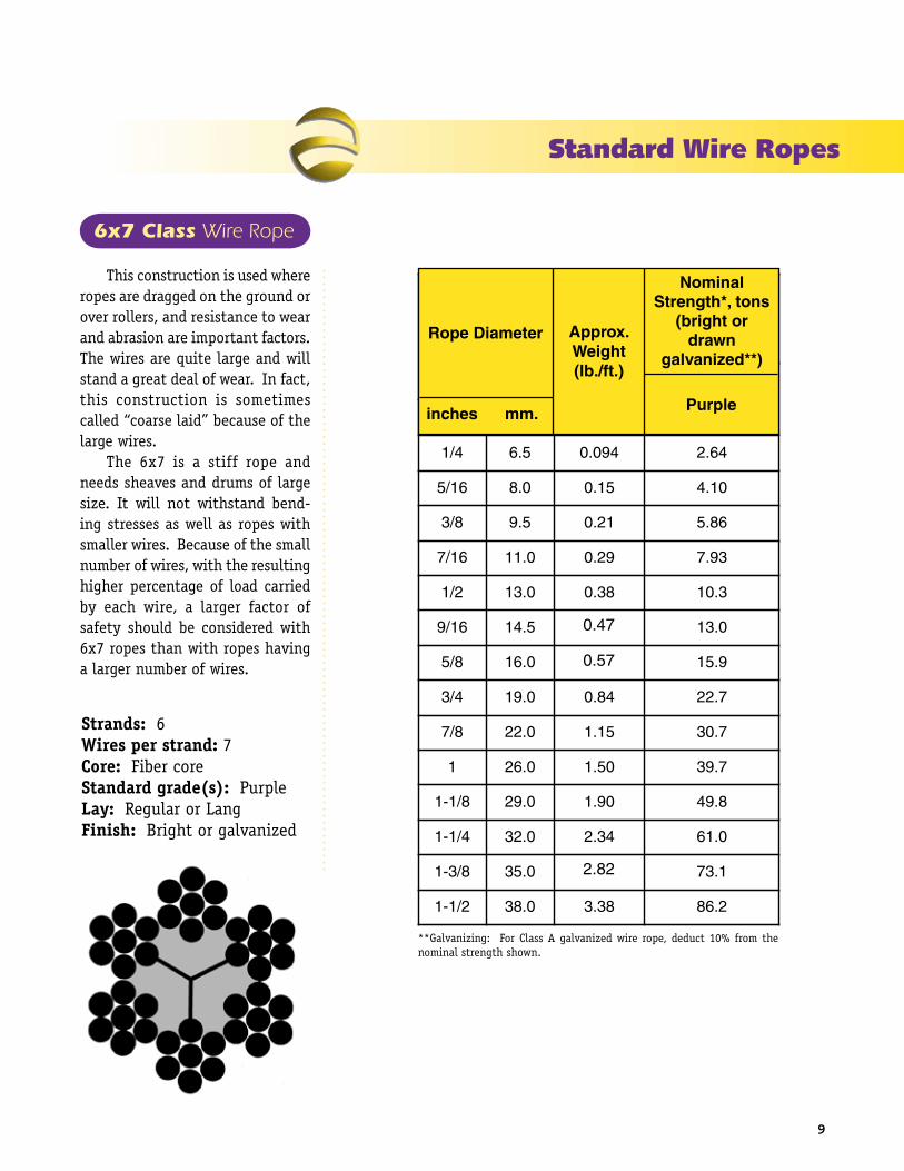
This construction is used where ropes are dragged on the ground or over rollers, and resistance to wear and abrasion are important factors. The wires are quite large and will stand a great deal of wear. In fact, this construction is sometimes called “coarse laid” because of the large wires. The 6x7 is a stiff rope and needs sheaves and drums of large size. It will not withstand bend-ing stresses as well as ropes with smaller wires. Because of the small number of wires, with the resulting higher percentage of load carried by each wire, a larger factor of safety should be considered with 6x7 ropes than with ropes having a larger number of wires.
6x7 Class Wire Rope
Strands: 6Wires per strand: 7Core: Fiber coreStandard grade(s): PurpleLay: Regular or LangFinish: Bright or galvanized
retemaiDepoR .xorppAthgieW).tf/.bl(
lanimoNsnot,*htgnertS
rothgirb(nward
)**dezinavlag
elpruPsehcni .mm
4/1 5.6 490.0 46.2
61/5 0.8 51.0 01.4
8/3 5.9 12.0 68.5
61/7 0.11 92.0 39.7
2/1 0.31 83.0 3.01
61/9 5.41 84.0 0.31
8/5 0.61 95.0 9.51
4/3 0.91 48.0 7.22
8/7 0.22 51.1 7.03
1 0.62 05.1 7.93
8/1-1 0.92 09.1 8.94
4/1-1 0.23 43.2 0.16
8/3-1 0.53 48.2 1.37
2/1-1 0.83 83.3 2.68
lanimonehtwoleb%2/1-2nahtsseltonsihtgnertsecnatpeccA*.sbl000,2fosnoT.detsilshtgnerts
%01tcuded,eporeriwdezinavlagAssalCroF:gnizinavlaG**.nwohshtgnertslanimonehtmorf
**Galvanizing: For Class A galvanized wire rope, deduct 10% from the nominal strength shown.
0.47
0.57
2.82
Rope Diameter Approx.Weight(lb./ft.)
NominalStrength*, tons
(bright ordrawn
galvanized**)
Purpleinches mm.

10
Standard Wire Ropes
6x19 Class Wire Rope
Strands: 6Wires per strand: 19 to 26Core: IWRC or fiber coreStandard Grade: Purple PlusLay: Regular or LangFinish: Bright or galvanized
The 6x19 Classification of wire rope is the most widely used. With its good combination of flexibility and wear resistance, rope in this class can be suited to the specific needs of diverse kinds of machinery and equipment. The 6x19 Seale construction, with its large outer wires, provides great ruggedness and resistance to abrasion and crushing. How-ever, its resistance to fatigue is somewhat less than that offered by a 6x25 construction. The 6x25 possesses the best combination of flexibility and wear resistance in the 6x19 Class due to the filler wires providing support and im-parting stability to the strand. The 6x26 Warrington Seale construction has a high resistance to crushing. This construction is a good choice where the end user needs the wear resistance of a 6x19 Class Rope and the flexibility midway between a 6x19 Class and 6x37 Class rope.
6x19 Warrington with fiber core
6x19 Seale with IWRC
6x26 Warrington Seale with IWRC
6x31 Warrington Seale with IWRC
6x49 Filler Wire Seale with IWRC6x25 Filler Wire with IWRC 6x36 Warrington Seale IWRC
6x36 Class Wire Rope
Strands: 6Wires per strand: 27 to 49Core: IWRC or fiber coreStandard Grade: Purple PlusLay: Regular or LangFinish: Bright or galvanized
The 6x36 Class of wire rope is characterized by the relatively large number of wires used in each strand. Ropes of this class are among the most flexible avail-able due to the greater number of wires per strand, however their resistance to abrasion is less than ropes in the 6x19 Class. The designation 6x36 is only nominal, as in the case with the 6x19 Class. Improvements in wire rope design, as well as changing machine designs, have resulted in the use of strands with widely vary-ing numbers of wires and a smaller number of available constructions. Typical 6x37 Class constructions include 6x33 for diameters under 1/2", 6x36 Warrington Seale (the most common 6x37 Class construc-tion) offered in diameters 1/2" through 1-5/8", and 6x49 Filler Wire Seale over 1-3/4" diameter.

Standard Wire Ropes
11
6x19 Class
6x19 Seale
6x19 Warrington
6x21 Filler Wire Type U
6x21 Seale
6x25 Filler Wire Type W
6x25 Seale
6x26 Warrington Seale
6x36 Class
6x31 Warrington Seale
6x33
6x36 Warrington Seale
6x41 Warrington Seale
6x43 Filler Wire Seale
6x49 Filler Wire Seale
Technical data for the above listed constructions are the same and are detailed in the table. For further information on
additional constructions and diameters, contact WW’s customer service department.
retemaiDepoRthgieW.xorppA
).tf/.bl(
snot,*htgnertSlanimoN)**dezinavlagnwardrothgirb(
elpruPlayoR sulPelpruP
sehcni .mmrebiFeroC
CRWI CRWI eroCrebiF CRWI
4/1 5.6 501.0 611.0 47.3 10.3 04.3
61/5 0.8 461.0 81.0 08.5 96.4 72.5
8/3 5.9 632.0 62.0 03.8 17.6 55.7
61/7 0.11 23.0 53.0 2.11 01.9 2.01
2/1 0.31 24.0 64.0 6.41 8.11 3.31
61/9 5.41 35.0 95.0 5.81 9.41 8.61
8/5 0.61 06.0 27.0 7.22 4.81 6.02
4/3 0.91 59.0 40.1 4.23 2.62 4.92
8/7 0.22 92.1 24.1 8.34 4.53 8.93
1 0.62 86.1 58.1 9.65 0.64 7.15
8/1-1 0.92 31.2 43.2 5.17 9.75 0.56
4/1-1 0.23 36.2 98.2 9.78 1.17 9.97
8/3-1 0.53 81.3 05.3 0.601 5.58 0.69
2/1-1 0.83 87.3 61.4 0.521 0.101 0.411
8/5-1 0.24 44.4 88.4 0.641 0.811 0.231
4/3-1 0.54 51.5 76.5 0.961 0.631 0.351
8/7-1 0.84 19.5 05.6 0.291 0.551 0.471
2 0.25 27.6 93.7 0.712 0.671 0.891
8/1-2 0.45 95.7 53.8 0.342 0.791 0.122
4/1-2 0.85 15.8 63.9 0.272 0.022 0.742
8/3-2 0.06 84.9 4.01 0.103 0.442 0.472
2/1-2 0.46 5.01 6.11 0.233 0.962 0.203
4/3-2 0.07 7.21 0.41 0.793 0.123 0.163
.sbl000,2fosnoT.detsilshtgnertslanimonehtwoleb%2/1-2nahtsseltonsihtgnertsecnatpeccA*
lanimonehtmorf%01tcuded,)ylnoedargPIE(eporeriwdezinavlagAssalCroF:gnizinavlaG**.nwohshtgnerts
6x19 and 6x36 Classes Technical Data
0.12
0.58
1.41
3.49
5.66
6.49
8.34
9.35
0.11
0.16
0.24
0.53
0.66
6.73
7.60
8.52
9.49
retemaiDepoRthgieW.xorppA
).tf/.bl(
snot,*htgnertSlanimoN)**dezinavlagnwardrothgirb(
elpruPlayoR sulPelpruP
sehcni .mmrebiFeroC
CRWI CRWI eroCrebiF CRWI
4/1 5.6 501.0 611.0 47.3 10.3 04.3
61/5 0.8 461.0 81.0 08.5 96.4 72.5
8/3 5.9 632.0 62.0 03.8 17.6 55.7
61/7 0.11 23.0 53.0 2.11 01.9 2.01
2/1 0.31 24.0 64.0 6.41 8.11 3.31
61/9 5.41 35.0 95.0 5.81 9.41 8.61
8/5 0.61 06.0 27.0 7.22 4.81 6.02
4/3 0.91 59.0 40.1 4.23 2.62 4.92
8/7 0.22 92.1 24.1 8.34 4.53 8.93
1 0.62 86.1 58.1 9.65 0.64 7.15
8/1-1 0.92 31.2 43.2 5.17 9.75 0.56
4/1-1 0.23 36.2 98.2 9.78 1.17 9.97
8/3-1 0.53 81.3 05.3 0.601 5.58 0.69
2/1-1 0.83 87.3 61.4 0.521 0.101 0.411
8/5-1 0.24 44.4 88.4 0.641 0.811 0.231
4/3-1 0.54 51.5 76.5 0.961 0.631 0.351
8/7-1 0.84 19.5 05.6 0.291 0.551 0.471
2 0.25 27.6 93.7 0.712 0.671 0.891
8/1-2 0.45 95.7 53.8 0.342 0.791 0.122
4/1-2 0.85 15.8 63.9 0.272 0.022 0.742
8/3-2 0.06 84.9 4.01 0.103 0.442 0.472
2/1-2 0.46 5.01 6.11 0.233 0.962 0.203
4/3-2 0.07 7.21 0.41 0.793 0.123 0.163
.sbl000,2fosnoT.detsilshtgnertslanimonehtwoleb%2/1-2nahtsseltonsihtgnertsecnatpeccA*
lanimonehtmorf%01tcuded,)ylnoedargPIE(eporeriwdezinavlagAssalCroF:gnizinavlaG**.nwohshtgnerts

12
Alternate Lay Wire Rope
Alternate Lay, sometimes
referred to as reverse lay, is a
stranded rope where the type of
lay of the outer strands is alter-
nately regular lay followed by lang
lay such that three of the outer
strands are regular lay and three
are lang lay.
Alternate lay wire rope has
the extra flexibility of lang lay in
combination with the structural
stability of regular lay. It unites
the best features of both types of
wire rope.
Alternate lay is made with
relatively large outer wires to pro-
vide increase of abrasion resistance
to scrubbing against sheaves and
drums. Finer inside wires and flex-
ibility enable alternate lay ropes to
absorb severe bending stresses. It is
well suited to winding applications
where abrasion and crushing can
occur.
Alternate lay wire rope appli-
cations include boom hoists and
nume rous types of excavating
equipment like clamshells, shovels,
cranes, winches and scrapers.
Nominal Strength Rope Diameter Approx. tons Weight (lb./ft.) Purple Plus
inches mm.
1/2 13.0 0.46 13.3
9/16 14.5 0.59 16.8
5/8 16.0 0.72 20.6
3/4 19.0 1.04 29.4
7/8 22.0 1.42 39.8
1 26.0 1.85 51.7
1-1/8 29.0 2.34 65.0
1-1/4 32.0 2.89 79.9
Standard Wire Ropes
Strands: 6Wires per strand: 26Core: IWRCStandard Grade: Purple PlusLay: CombinationFinish: Bright

13
Rotation-Resistant Ropes
In certain instances the use of rotation-resistant wire rope is neces-sary to provide rotational stability to the lifted load. In general, the use of these wire ropes is limited to those situations where it is impractical to:
1. Use a tag line. 2. Relocate rope dead end. 3. Increase sheave sizes. 4. Eliminate “odd-part” reeving. 5. Significantly reduce rope loading and rope fall length.
Rotation-resistant wire ropes have less of a tendency to unlay when loaded than do conventional wire ropes. This results in improved rotational stability to the lifted load. Rotation-resistant wire ropes are designed in such a way that the rotational force of the outer strands is partially counteracted by the rotational force of the inner strands or core when the rope is subjected to a load. The chart compares the rotational properties of rotation-resistant ropes with a standard 6x25 wire rope. The rotation-resistant ropes far surpass the
rotational stability of a conventional 6x25 IWRC wire rope on both short and long falls.
Safety Design Factors ASME B30.5 specifies that rota-tion-resistant ropes have a safety design factor of five or greater. The required strength design factor of rotation-resistant rope becomes very important from the standpoint of maintaining the inherent low rota-tion of the rope and eliminating any tendency to overload the inner core, thereby causing a reduction in rope strength.
Handling & Installation Precautions should be followed when using rotation-resistant wire rope. The rope ends must be properly seized and secured (refer to Handling and Installation: Seizing Wire Rope) and cut with a saw or impact hammer to prevent unlaying of the strands. Attachment of end fittings must be done with care to prevent kinking or unlaying of rope, which harms the rotational balance of the rope.
Due to the opposite lay direction of the inner core and outer strand layers in rotation-resistant ropes, care should be taken to avoid shockloading. Shockloading will result in distortion of the rope structure, causing birdcag-ing, core protrusion, etc. Due to the potential for complete rope failure, shockloaded wire ropes must be im-mediately removed from service.
Swivels Operation of 8x25, 19x7 and SPF 19 rotation-resistant wire ropes with a swivel is not rec-ommended by WW. The use of a swivel allows the inner core to twist tighter, resulting in a significant reduction in rope strength, possibly leading to premature rope failure. A swivel may be used as a tempo-rary device only during the initial installation period to help eliminate any installation-induced twisting or cabling. The swivel must be removed from the reeving after rope instal-lation is completed and before the crane begins operation. A swivel may be used with SFP 35 Rotation Resistant Ropes.
Rotational Property Comparison
SFP 35

Rotation Resistant Ropes
14
The rated strengths of the 8x19 Class and 19x7 wire ropes are less than wire ropes in the 6x19 and 6x37 Classes. Larger sheaves are required in order to achieve comparable fatigue life. Refer to Technical Information: Effect of Sheave Size for further information on proper sheave sizes.
The 8x19 Classification rotation-resistant ropes are recommended for hoisting unguided loads with a single-part or multipart line. The eight outer strands are manufactured in right lay, with the inner strands being left lay. These ropes are slightly stron-ger and significantly more rugged than the 19x7 construction. How-ever, the rotation-resistant proper-ties of the 8x19 rotation-resistant ropes are much less than those of the 19x7 construction. These ropes are manufactured in right regular lay in the 8x19 Seale and 8x25 Filler Wire construc-tions.
19x7 is recommended for hoisting unguided loads with a single-part line. The rotation-resistant proper-ties of this rope are secured by two layers of strands. The inner strands are left lay, while the 12 outer strands are right lay, which enables one layer to counteract the other layer's rotation. The rotation-resistant charac-teristics of the 19x7 wire ropes are superior to those of the 8x19 Class wire ropes.
Strands: 19Wires per strand: 7Core: WSCStandard grade(s): Purple PlusLay: RegularFinish: Bright
Strands: 8Wires per strand: 19 to 25Core: IWRCStandard grade(s): Purple PlusLay: Right RegularFinish: Bright
retemaiDepoR .xorppAthgieW).tf/.bl(
lanimoNhtgnertS*)snot(
sehcni .mmelpruP
sulP
61/7 0.11 63.0 0.9
2/1 0.31 74.0 6.11
61/9 5.41 06.0 7.41
8/5 0.61 37.0 1.81
4/3 0.91 60.1 9.52
8/7 0.22 44.1 0.53
1 0.62 88.1 5.54
8/1-1 0.92 93.2 3.75
4/1-1 0.23 49.2 5.07
8/3-1 0.53 65.3 9.48
2/1-1 0.83 42.4 0.001
ehtwoleb%2/1-2nahtsseltonsihtgnertsecnatpeccA*.sbl000,2fosnoT.detsilshtgnertslanimon
retemaiDepoR .xorppAthgieW).tf/.bl(
lanimoNhtgnertS*)snot(
sehcni .mmelpruP
sulP
61/7 0.11 053.0 33.8
2/1 0.31 054.0 08.01
61/9 5.41 085.0 06.31
8/5 0.61 017.0 08.61
4/3 0.91 020.1 00.42
8/7 0.22 093.1 05.23
1 0.62 028.1 02.24
8/1-1 0.92 003.2 01.35
4/1-1 0.23 048.2 01.56
8/3-1 0.53 034.3 04.87
2/1-1 0.83 080.4 08.29
ehtwoleb%2/1-2nahtsseltonsihtgnertsecnatpeccA*.sbl000,2fosnoT.detsilshtgnertslanimon
8x19 Classification Rotation-Resistant
19x7 Rotation-Resistant

15
SFP 19 is recommended for both multipart load and single-part fast line applications where rotational stability of the lifted load is needed, such as for use as a long fall on off-shore pedestal cranes, rough and all terrain cranes, and crawler cranes. SFP 19 provides: Fatigue Resistance. Improved fatigue properties are derived through the combination of the flexible 19x19 construction and die drawn strands. The drawn strand surfaces minimize the interstrand and interlayer nicking that take place in round rotation-resistant ropes. Abrasion Resistance. Die drawn ropes provide improved abrasion re-sistance as compared with round wire ropes because of the greater wire and strand bearing surfaces contacting sheaves and drums. Resistance to Drum Crushing. SFP 19 wire ropes are resistant to the effects of drum crushing due to the compacted strands and smoothness of the rope surface.
Strands: 19Wires per strand: 7/19Core: WSCStandard grade(s): Royal PurpleLay: Right RegularFinish: Bright
Rotation-Resistant Ropes
Super Flex Pac 19
retemaiDepoR .xorppAthgieW).tf/.bl(
lanimoNhtgnertS*)snot(
sehcni .mmlayoRelpruP
2/1 0.31 45.0 6.41
61/9 5.41 96.0 5.81
8/5 0.61 38.0 7.22
4/3 0.91 91.1 4.23
8/7 0.22 26.1 8.34
1 0.62 21.2 9.65
8/1-1 0.92 86.2 5.17
4/1-1 0.23 13.3 9.78
8/3-1 0.53 10.4 0.601
2/1-1 0.83 77.4 0.521
ehtwoleb%2/1-2nahtsseltonsihtgnertsecnatpeccA*.sbl000,2fosnoT.detsilshtgnertslanimon
Super Flex Pac 35
SFP 35 is a rotation-resistant rope of high strength that can resist block twist in long falls. SFP 35 provides: Superior Rota-tion Resistance—the SFP 35 rope is the most rotation resistant rope man-ufactured by WW. Due to its rotation-resistant properties, SFP 35 may be used with a swivel in both single part and multipart reeving. High Strength. WW’s compaction process provides a high strength rope which exceeds EEIP nominal breaking strength. Application. SFP 35 excels in crawler and truck-type crane load lines, and tower crane hoist ropes. Flexibility. SFP 35’s multiple strand construction provides increased flexibility which improves service life and high speed spooling. The com-
pacted multiple strand construction also reduces sheave and drum abra-sion and provides excellent resistance to drum crushing. Strands: 35Wires per strand: 7Core: WSCStandard grade(s): 2160 N/mm2
Lay: Right RegularFinish: Bright
Rope Diameter Approx. Weight Nominal Strength
mm inches (kg/m) (lb/ft) (kN)* (tons)
19 1.79 344
3/4 1.21 38.70
22 2.40 466
7/8 1.65 53.00
1 2.15 70.00
26 3.36 660
28 3.90 758
1 1/8 2.73 86.90
Note: 5/8 and below 19x7 construction; 3/4 and larger 19x19 construction

Specialized Wire Rope
16
The charts shown to the right are meant to serve as a quick reference guide in selecting a specialized wire rope. The increased strengths of the spe-cialized ropes are derived from greater metallic areas. Whether the greater metallic areas are caused by die drawn strands (6-Pac) or a combination of die drawn strands and swaging (Super-Pac and Triple-Pac), these manufacturing processes create denser rope cross sec-tions, thus increasing the ropes’ break-ing strengths. Also contributing to the increase in strength for the die drawn strand ropes is the flat, smooth finish to the strands which eliminates inter-strand nicking and enables the load placed upon the wire rope to increase without causing internal damage. Abrasion resistance and flexibility are determined by two factors—outer wire size and method of compac-tion. Generally, the larger the outer wire size, the greater the abrasion resistance. For example, a 6x25 wire rope is manufactured with an outer wire size greater than that of a 6x36. Therefore, the 6x25 wire rope is more resistant to abrasion. Abrasion resis-tance is also determined by compac-tion. The greater the compaction, the greater the abrasion resistance, as in the case of Super-Pac and Triple-Pac. Conversely, wire ropes manufactured with small wire sizes offer greater flexibility than those with large outer wires. Again using 6x25 and 6x36 as an example, the 6x36 with smaller outside wires is clearly more flexible. Further, compaction may either enhance or hinder flexibility. Die drawn strands (6-PAC) enhance flexibility due to the strands' flat surface areas reduc-ing internal resistance, enabling the strands to better move in conjunction with each other. Swaging, on the other hand, hinders flexibility, as evidenced by Super-Pac and Triple-Pac.
6x25 6x366-Pac
8-Pac
TriplePac
Super-Pac
6x36
6x258-Pac
6-Pac
TriplePac
Super-Pac
6x25
6-Pac
TriplePacSuper-
Pac
6x368-Pac
Breaking Strength Comparison
Abrasion Resistance Comparison
Flexibility Comparison

17
6-PAC is recommended for use where the rope is subjected to heavy use or where conditions are extremely abusive, such as offshore pedestal, crawler and lattice boom equipped truck crane boom hoist applications. 6-PAC is also recommended for winch lines, overhead cranes, multipart hoist lines where rotation-resistant ropes are not required, and other applications where flexibility, high strength and resistance to crushing are important, and a cost-effective 6-strand rope is desired.6-PAC provides: Fatigue Resistance. Improved fatigue properties are derived from the combination of 6-PAC’s flexible constructions and the compacted strands. The compacted strand surface minimizes the interstrand and interlayer nicking that take place in standard 6-strand ropes. Abrasion Resistance. 6-PAC’s compacted strand design provides improved abrasion resistance as compared to standard 6-strand ropes because of the increased wire and strand surfaces contacting sheaves and drums. Flexibility. 6-PAC’s design pro-vides increased flexibility, making it easy to install, and 6-PAC also offers better spooling at high line speeds. Resistance To Multilayer Drum Crushing. 6-PAC dra-matically increases the amount of wire contact with the drums and sheaves, reducing the wire rope, sheave and drum wear normally associated with standard wire rope. Damage at the crossover points is also reduced.
6-PAC
Strands: 6Wires per strand: 19 to 36Core: IWRCStandard grade(s): Royal PurpleLay: Right RegularFinish: Bright
Specialized Wire Rope
retemaiDepoR dradnatS-urtsnoC
snoitc
.xorppAthgieW).tf/.bl(
lanimoNhtgnertS*)snot(
sehcni .mmlayoRelpruP
8/3 5.991x6elaeS
582.0 3.8
61/7 0.1191x6elaeS
883.0 2.11
2/1 0.31 62x6 305.0 6.41
61/9 5.41 62x6 246.0 5.81
8/5 0.61 62x6 597.0 7.22
4/3 0.91 13x6 341.1 4.23
8/7 0.22 13x6 745.1 8.34
1 0.62 13x6 570.2 9.65
8/1-1 0.92 13x6 575.2 5.17
4/1-1 0.23 13x6 961.3 9.78
8/3-1 0.53 63x6 857.3 0.601
2/1-1 0.83 63x6 465.4 0.521
8/5-1 3.14 63x6 653.5 0.641
4/3-1 5.54 63x6 212.6 0.961
shtgnertslanimonehtwoleb%2/1-2nahtsseltonsihtgnertsecnatpeccA*.sbl000,2fosnoT.detsil
roF caphteB s'WWWotreferesaelp,retemaid"4/3-1revoCAP-6ro,ecivresremotsucruotcatnocro,golatacstcudorPgniniMmehelhteB
.tnemtraped
For Bethpac, or 6-PAC over 1-3/4” diameter, please refer to WW’s Bethlehem Mining Products catalog, or contact our customer service department.

ASME Rules & GuidelinesSpecialized Wire Rope
8-PAC
18
8-PAC is recommended for
hoist ropes for steel mill ladle
cranes and hoist and trolley
ropes for container cranes, or
other hoisting applications with
heavy duty cycles or where se-
vere bending occurs.
Other features of 8-PAC include:
Superior Performance. 8-PAC
has higher breaking strength
and gives superior performance
in difficult hoisting applications
compared to standard 6-strand and
6-strand compacted ropes.
Abrasion Resistance. 8-PAC
compacted strand design provides
improved abrasion resistance as
compared to standard 6 and 8 strand
ropes because of the increased wire
and strand surfaces contacting the
sheaves and drums.
Superior Flexibility. 8-PAC
is significantly more flexible than
standard 6 and compacted 6 strand
ropes with better spooling and
longer service life.
Resistance To Multilayer
Drum Crushing. 8-PAC’s plastic-
filled (BXL) core offers increased
resistance to crushing through bet-
ter support of the outer strands.
Minimum Approx. Breaking Standard Weight Strength inches Construction (lb/ft) (net tons)
5/8 8x26 WS 0.80 25.0
3/4 8x26 WS 1.17 36.0
7/8 8x26 WS 1.60 48.3
1 8x26 WS 2.10 62.8
1 1/8 8x26 WS 2.63 79.0
1 1/4 8x31 WS 3.26 98.0NOTE: Other sizes available
Rope Diameter
Strands: 8Wires per strand: 19 to 36Core: Plastic filled (BXL)Standard grade(s): Royal PurpleLay: Right Finish: Bright

19
Specialized Wire Rope
SUPER-PAC
SUPER-PAC is a double compacted product ideal for applications where abrasion and drum crush-ing are an issue. When compared with standard ropes, SUPER-PAC provides: Better resistance to multi-layer drum crushing. SUPER-PAC dramatically reduces the dam-age at cross over points on smooth face drums, such as those found on many boom hoist systems on mobile cranes. This is achieved by compaction of the strands and the rope, making a tough but flexible product. Abrasion Resistance. The compaction process also increases the contact between the rope and the drum and sheaves, reducing sheave and drum wear. Super Strength. The double compaction process also increases the minimum breaking strength of standard EIP rope more than 20%. Superior Fatigue Resistance. SUPER-PAC is engineered for over-all performance, its wire tensile strength being the key to its supe-rior fatigue resistant properties. In addition to contribution to SUPER-PAC’s EEEIP breaking strength, the wire used in the manufacture of SUPER-PAC remains ductile, mini-mizing the occurrences of external and internal wire breaks caused by operating stresses. Application. SUPER-PAC is ideal for all types of boom hoist and lowering ropes.
Approx. Nominal Rope Diameter Weight Strength
inches mm (lb/ft) (tons)
5/8 16 0.995 29
3/4 19 1.43 40
7/8 22 1.92 52
1 26 2.42 68
1-1/8 29 2.96 85
1-1/4 32 3.51 102
Strands: 6Wires per strand: 26/31Core: IWRCStandard grade(s): Royal Purple PlusLay: Right RegularFinish: Bright

20
ASME Rules & GuidelinesSpecialized Wire Rope
TRIPLE-PAC
TRIPLE-PAC was developed for the most demanding hoist applications. TRIPLE-PAC offers the extra high strength and crushing resistance needed for applications such as boom hoist ropes, boom pendants and multi-part load lines. TRIPLE-PAC provides superior abrasion and fatigue resistance as compared with most compacted ropes due to WW’s unique design of compacting the IWRC, individual strands and the rope itself. Other benefits include: High Strength. TRIPLE-PAC is designed to provide a nominal strength of 35% above EIP. WW achieves this strength through selected grades of steel and TRIPLE-PAC’s unique design and manufac-turing processes. Superior Resistance to Multi- layer Drum Crushing. TRIPLE-PAC provides superior resistance to crushing through its design. Its triple compaction provides a denser cross section, enabling the rope to withstand the rigors of multilayer spooling. Damage at the cross over points is also significantly reduced. In addition, TRIPLE-PAC’s design in-creases the amount of wire contact with sheaves and drums, reducing wire rope, drum and sheave wear.
retemaiDepoRdradnatS-urtsnoC
snoitc
.xorppAthgieW).tf/.bl(
lanimoNhtgnertS*)snot(
sehcni .mmlayoRelpruP
sulP
61/7 0.11 62x6 214.0 8.31
2/1 0.31 62x6 345.0 0.81
61/9 5.41 62x6 086.0 7.22
8/5 0.61 62x6 048.0 8.72
4/3 0.91 63ro13x6 792.1 7.93
8/7 0.22 63ro13x6 646.1 7.35
1 0.62 63ro13x6 741.2 8.96
8/1-1 0.92 63ro13x6 227.2 8.78
4/1-1 0.23 63ro13x6 792.3 9.701
8/3-1 0.53 63ro13x6 799.3 6.921
2/1-1 0.83 63ro13x6 938.4 9.351
shtgnertslanimonehtwoleb%2/1-2nahtsseltonsihtgnertsecnatpeccA*.sbl000,2fosnoT.detsil
.412
.543
.681
.858
1.30
1.72
2.30
2.89
3.54
4.04
4.99
Strands: 6Wires per strand: 26/31 or 36Core: IWRCStandard grade(s): Royal Purple PlusLay: Right Regular

Specialized Wire Rope
21
BXL is infused with a special-ly-engineered polymer, creating a well-balanced matrix. BXL is recommended for numerous hoist, marine and logging rope applications. BXL provides: Fatigue Resistance. Improved fatigue resistance is derived from the cushionin g and dampening effect of the polymer on the wires and strands. BXL also evenly dis-tributes stresses which may lead to fatigue breaks. Abrasion Resistance. The polymer acts as a barrier between the individual strands, preventing penetration of any adverse mate-rial. BXL distributes and reduces contact stresses between the rope and sheave, reducing wire rope wear. Resistance To Multilayer Drum Crushing. BXL’s smooth profile evenly distributes crushing pressures from the overlying layers of rope in multilayer drum winding applications. Extended Sheave And Drum Service Life. BXL minimizes corrugation and wear normally associated with standard rope us-age by restricting water and dirt penetration and eliminating pickup of abrasive materials. Clean Handling. The exterior rope surface is free from the grease normally applied to standard ropes.
BXL
retemaiDepoR .xorppAthgieW).tf/.bl(
lanimoNhtgnertS*)snot(
sehcni .mmelpruP
sulP
8/3 5.9 72.0 55.7
61/7 0.11 73.0 2.01
2/1 0.31 94.0 3.31
61/9 5.41 16.0 8.61
8/5 0.61 67.0 6.02
4/3 0.91 90.1 4.92
8/7 0.22 94.1 8.93
1 0.62 49.1 7.15
8/1-1 0.92 64.2 0.56
4/1-1 0.23 30.3 9.97
8/3-1 0.53 76.3 0.69
2/1-1 0.83 73.4 0.411
ehtwoleb%2/1-2nahtsseltonsihtgnertsecnatpeccA*.sbl000,2fosnoT.detsilshtgnertslanimon
:etonesaelP elbatehtnidetsilshtgnertsehTro,LXB.sessalC73x6dna91x6ehtylnotcelfer,stcudorpynamotdeddaebyam,noisufni-citsalpsiflestieporehthcihwnisngisedeporgnidulcxeesaelp,noitamrofnilanoitiddaroF.detcapmoc
.tnemtrapedecivresremotsucs'WWWtcatnoc
Please note: The strengths listed in the table reflect only the 6x19 and 6x36 classes. BXL, or plastic-infusion, may be added to many products, excluding rope designs in which the rope itself is compacted. For additional information, please contact WW’s customer service department.
Strands: 6Wires per strand: 19 to 36Core: IWRCStandard grade(s): Purple PlusLay: Regular or LangFinish: Plastic-infused

FLATTENED STRAND
This rope is particularly suit-
able where severe conditions of
crushing and abrasion are en-
countered on the drum or where
a higher strength design factor
is required than can be obtained
with a similar round rope.
The triangular strand shape not
only provides better resistance to
crushing, but also offers a greater
exposed surface area for contact
with sheaves, drums or underlying
layers of spooled rope. This fea-
ture, in connection with the use of
Lang lay construction, distributes
the abrasive wear over a greater
number and length of wires.
The smooth surface of the rope
also helps minimize wear on drums
and sheaves.
retemaiDepoRthgieW.xorppA
).tf/.bl(
,*htgnertSlanimoNsnot
sulPelpruP
sehcni .mm eroCrebiF CRWI eroCrebiF CRWI
8/1-1 0.92 82.2 93.2 7.36 5.86
4/1-1 0.23 18.2 59.2 1.87 48
8/3-1 0.53 04.3 75.3 1.49 101
2/1-1 0.83 50.4 52.4 111 911
8/5-1 0.24 57.4 99.4 031 041
4/3-1 0.54 15.5 97.5 251 161
8/7-1 0.84 33.6 56.6 171 481
2 0.25 02.7 65.7 491 702
8/1-2 0.45 31.8 45.8 512 332
4/1-2 0.85 01.9 65.9 042 062
.detsilshtgnertslanimonehtwoleb%2/1-2nahtsseltonsihtgnertsecnatpeccA*.sbl000,2fosnoTStrand: 6
Wires per strand: 27Core: IWRC or fiber coreStandard Grade(s): Purple PlusLay: LangFinish: Bright
22
ASME Rules & GuidelinesSpecialized Wire Rope

Specialized Wire Rope
ROEPAC is a three strand com-
pacted rope with high breaking
strength and stable construction
making it perfect as a pulling rope
for overhead transmission lines
and underground conduits. It’s
flexibility and flat surface provides
snag-free guidance of the attached
lines.
Abrasion Resistance. Com-
pacted design provides improved
abrasion resistance compared to
standard 6 strand ropes because
of the increased Wire and strand
surfaces contacting the sheaves
and drum.
Resistance to Drum Crush-
ing. ROEPAC’s compact design of-
fers increased resistance to drum
crushing.
Strands: 3Wires per strand: 19/37/43Core: NoneLay: Right RegularFinish: Bright
ROEPAC COMPACTED
23
Minimum Approx. Breaking Diameter Standard Weight Strength (inches) Construction (lb/ft) (short tons)
3/8 3x19 .295 8.4
7/16 3x19/37 .409 11.4
1/2 3x19/37 .542 14.8
5/8 3x37 .767 21.7
3/4 3x37 1.123 31.1
7/8 3x43 1.568 42.1
1 3x43 2.067 54.7
1 1/8 3x43 2.561 68.9

Oil Field & Natural Gas Drilling Products
6x19 Rotary Drilling Line
Rotary Drill Lines
Steel Core
EIP EEIP
Minimum Minimum Approx. Breaking Breaking Diameter Standard Weight Strength Strength Diameter (inches) Construction (lb/ft) (net tons) (net tons) (inches)
1 6x19 S 1.85 51.7 56.9 1
1 1/8 6x19 S 2.34 65.0 71.5 1 1/8
1 1/4 6x19 S 2.89 79.9 87.9 1 1/4
1 3/8 6x19 S 3.50 96 106 1 3/8
1 1/2 6x19 S 4.16 114 125 1 1/2
1 5/8 6x19 S/6x26 WS 4.88 132 146 1 5/8
1 3/4 6x19 S/6x26 WS 5.67 153 169 1 3/4
1 7/8 6x26 WS 6.50 174 192 1 7/8
2 6x26 WS 7.39 198 217 2 *All drill lines have asphaltic lube, post lubed, and are RRL
Cable Tool Lines
Fiber Core
Minimum Approx. Breaking Diameter Standard Weight Strength Diameter (inches) Construction (lb/ft) (net tons) (inches)
5/8 6x21 Left Lay 0.66 14.5 5/8
3/4 6x21 Left Lay 0.95 20.7 3/4
7/8 6x21 Left Lay 1.29 28.0 7/8
1 6x21 Left Lay 1.68 36.4 1
*All cable lines have petrolatum lube, are LRL, and FC
Sand Lines
Fiber Core
Minimum Approx. Breaking Diameter Standard Weight Strength Diameter (inches) Construction (lb/ft) (net tons) (inches)
3/8 6x7 0.21 5.86 3/8
7/16 6x7 0.29 7.93 7/16
1/2 6x7 0.38 10.3 1/2
9/16 6x7 0.48 13.0 9/16
9/16 6x7 galv 0.47 13.0 9/16
5/8 6x7 0.59 15.9 5/8
*All sand lines have petrolatum lube and are RRL
Tubing Lines
Steel Core
Minimum Approx. Breaking Diameter Standard Weight Strength Diameter (inches) Construction (lb/ft) (net tons) (inches)
7/8 6x26 WS 1.42 39.8 7/8
1 6x26 WS 1.85 51.7 1
1 1/8 6x26 WS 2.34 65.0 1 1/8
*All sand lines have petrolatum lube and are RRL
Features: Excellent balance between fatigue and wear resistance
6x21 Cable Tool Line
Features: Increased resistance to bending fatigue on Cable Tool Rigs
6x7 Sand Lines &Swabbing Lines
Features: High abrasion resistance
6x26 Tubing Line
Features: Excellent balance between fatigue and wear resistance
24

Oil Field and Natural Gas Drilling Products
Riser Tensioner Ropes
Steel Core
Minimum Approx. Breaking Diameter Standard Weight Strength Diameter (inches) (mm) Construction (lb/ft) (net tons) (inches)
1 3/4 45 6x49 5.6 146 1 3/4
1 7/8 48 6x49 6.6 167 1 7/8
2 52 6x49 7.5 189 2
2 1/8 54 6x49 8.3 211 2 1/8
2 1/4 58 6x49 9.4 236 2 1/4
2 3/8 60 6x49 10.3 263 2 3/8
2 1/2 64 6x49 11.7 288 2 1/2
2 5/8 67 6x57 12.5 317 2 5/8
2 3/4 70 6x57 13.8 345 2 3/4 *All tensioners have asphaltic lube, and are RLL or LLL
Swaged Tubing Lines
Steel Core
Minimum Approx. Breaking Diameter Standard Weight Strength Diameter (inches) Construction (lb/ft) (net tons) (inches)
7/8 6x26 WS 1.80 47 7/8
7/8 6x31 WS 1.82 47 7/8
1 6x26 WS 2.35 62 1
1 6x31 WS 2.26 62 1
*All swaged tubing lines have petrolatum lube and are RRL or LRL
Riser Tensioner Ropes
Features: Special construction and multiple wire tensile increasing fatigue resistance
Swaged Tubing Line
Features: Compacted rope and higher breaking strength, excellent crush resistance and abrasion resistance
6-Pac
EEIP
Minimum Approx. Breaking Diameter Standard Weight Strength (inches) Const. (lb/ft (net tons)
7/16 6x19 S 0.39 11.20
1/2 6x26 0.49 14.6
9/16 6x26 0.63 18.5
5/8 6x26 0.78 22.7
3/4 6x26 1.13 32.4
7/8 6x26 1.54 43.8
1 6x26 2.00 56.9
1 1/8 6x31 2.54 71.5
1 1/4 6x31 3.14 87.9
1 3/8 6x36 3.80 106
1 1/2 6x36 4.50 125
1 5/8 6x36 5.27 146
1 3/4 6x36 6.24 169
1 7/8 6x36 7.02 192
*All sand lines have petrolatum lube and are RRL
Super Pac
EEIP
Minimum Approx. Breaking Diameter Const. Weight Strength (inches) (lb/ft) (net tons)
1/2 6x26 0.65 18
9/16 6x26 0.81 23
5/8 6x26 1.00 29
3/4 6x31 1.43 40
7/8 6x31 1.92 52
1 6x26 2.42 68
1 1/8 6x26 2.96 85
1 1/8 6x36 2.96 85
1 1/4 6x26 3.51 100
1 1/4 6x36 3.51 100
1 3/8 6x26 4.31 120
1 3/8 6x36 4.31 120
*All sand lines have petrolatum lube and are RRL
6-PacFeatures: Compacted strand design provides improved service life and abrasion resistance
Increase flexibility to multilayer drum crushing
Super-PacFeatures: Compacted strand and rope design provides superior abrasion resistance
Excellent resistance to effects of drum crushing
Increased strength capability
Galvanized ProductsWW manufacturers most ropes with a gal-vanized coating on the individual wires. For rope specifics contact your Regional Sales Manager or Customer Service at 800-541-7673.
Anchor LinesRope and Strand anchor lines are designed to meet specific requirements.
25
The Wrong Way
The Right Way
26
Handling
Measuring Rope Diameter Rope diameter is specified by the user and is generally given in the equipment manufacturer’s instruction manual accompanying the machine on which the rope is to be used. Rope diameters are determined by measuring the circle that just touches the extreme outer limits of the strands — that is, the greatest dimension that can be measured with a pair of paral-lel-jawed calipers or machinist’s caliper square. A mistake could be made by measuring the smaller dimension.
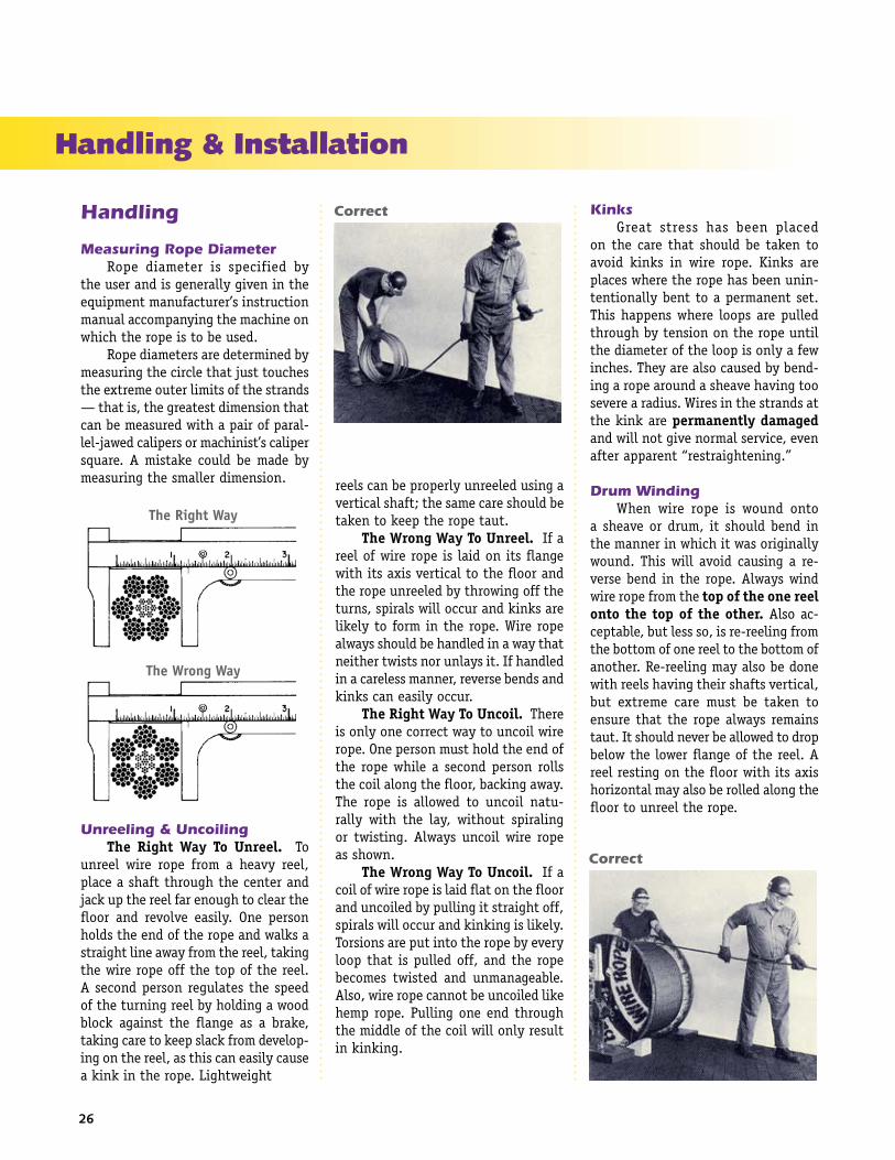
Unreeling & Uncoiling The Right Way To Unreel. To unreel wire rope from a heavy reel, place a shaft through the center and jack up the reel far enough to clear the floor and revolve easily. One person holds the end of the rope and walks a straight line away from the reel, taking the wire rope off the top of the reel. A second person regulates the speed of the turning reel by holding a wood block against the flange as a brake, taking care to keep slack from develop-ing on the reel, as this can easily cause a kink in the rope. Lightweight
reels can be properly unreeled using a vertical shaft; the same care should be taken to keep the rope taut. The Wrong Way To Unreel. If a reel of wire rope is laid on its flange with its axis vertical to the floor and the rope unreeled by throwing off the turns, spirals will occur and kinks are likely to form in the rope. Wire rope always should be handled in a way that neither twists nor unlays it. If handled in a careless manner, reverse bends and kinks can easily occur. The Right Way To Uncoil. There is only one correct way to uncoil wire rope. One person must hold the end of the rope while a second person rolls the coil along the floor, backing away. The rope is allowed to uncoil natu-rally with the lay, without spiraling or twisting. Always uncoil wire rope as shown. The Wrong Way To Uncoil. If a coil of wire rope is laid flat on the floor and uncoiled by pulling it straight off, spirals will occur and kinking is likely. Torsions are put into the rope by every loop that is pulled off, and the rope becomes twisted and unmanageable. Also, wire rope cannot be uncoiled like hemp rope. Pulling one end through the middle of the coil will only result in kinking.
Kinks Great stress has been placed on the care that should be taken to avoid kinks in wire rope. Kinks are places where the rope has been unin-tentionally bent to a permanent set. This happens where loops are pulled through by tension on the rope until the diameter of the loop is only a few inches. They are also caused by bend-ing a rope around a sheave having too severe a radius. Wires in the strands at the kink are permanently damaged and will not give normal service, even after apparent “restraightening.”
Drum Winding When wire rope is wound onto a sheave or drum, it should bend in the manner in which it was originally wound. This will avoid causing a re-verse bend in the rope. Always wind wire rope from the top of the one reel onto the top of the other. Also ac-ceptable, but less so, is re-reeling from the bottom of one reel to the bottom of another. Re-reeling may also be done with reels having their shafts vertical, but extreme care must be taken to ensure that the rope always remains taut. It should never be allowed to drop below the lower flange of the reel. A reel resting on the floor with its axis horizontal may also be rolled along the floor to unreel the rope.
Correct
Correct
Handling & Installation

27
Handling & Installation
Wire rope should be attached at the cor-rect location on a flat or smooth-faced drum, so that the rope will spool evenly, with the turns lying snugly against each other in even layers. If wire rope is wound on a smooth-face drum in the wrong direction, the turns in the first layer of rope will tend to spread apart on the drum. This results in the second layer of rope wedging between the open coils, crushing and flattening the rope as successive layers are spooled. A simple method of determining how a wire rope should be started on a drum is shown above. The observer stands behind the drum, with the rope coming towards him. Using the right hand for right-lay wire rope, and the left hand for left lay wire rope, the clenched fist denotes the drum, the extended index finger the oncoming rope.
Wire Rope Clips Clips are usually spaced about six wire rope diameters apart to give adequate holding power. They should be tightened before the rope is placed under tension. After the load is placed on the rope, tighten the clips again to take care of any lessening in rope diameter caused by tension of the load. A wire rope thimble should be used in the eye of the loop to prevent kinking.
The correct number of clips for safe operation and the spacing dis-tances are shown in the table. U-bolt Clips. There is only one correct method for attaching U-bolt clips to wire rope ends, as shown in The Right Way. The base of the clip bears on the live end of the rope; the “U” of the bolt bears on the dead end.
Compare this with the incorrect methods. Five of the six clips shown are incorrectly attached —only the center clip in the top view is correct. When the “U” of the clip bears on the live end of the rope, there is a possibil-ity of the rope’s being cut or kinked, with subsequent failure.
Twin-base Clips. Twin-base clips are installed as shown below. Due to their special design, they cannot be installed incorrectly.
The Right Way
The Wrong Way
Number of clips and spacing for safe application (center to center)
By holding the right hand or left hand with the index finger extended, palm up or palm down, the proper procedure for applying left and right lay rope can easily be determined.

ASME Rules & GuidelinesHandling & Installation
sretemaiDepoRdetsegguSeriWgnizieS
sretemaiD
sehcni .mm sehcni .mm
"61/5ot"8/1 0.8ot2.3 230. 318.0
"61/9ot"8/3 5.41ot5.9 840. 12.1
"61/51ot"8/5 0.42ot0.61 360. 06.1
"61/1-1ot"1 0.33ot0.62 080. 30.2
"61/11-1ot"8/1-1 0.34ot0.53 401. 46.2
regraldna"4/3-1 regraldna0.54 421. 51.3
.retemaidepornahtsselebtondluohsgniziesfohtgneL
Suggested Seizing Wire Diameters
Seizing Wire Rope Proper seizing and cutting opera-tions are not difficult to perform, and they ensure that the wire rope will meet the user’s performance expecta-tions. Proper seizings must be applied on both sides of the place where the cut is to be made. In a wire rope, care-lessly or inadequately seized ends may become distorted and flattened, and the strands may loosen. Subsequently, when the rope is operated, there may be an uneven distribution of loads to the strands; a condition that will significantly shorten the life of the rope. Either of the following seizing methods is acceptable. Method No. 1 is usually used on wire ropes over one inch in diameter. Method No. 2 applies to ropes one inch and under. Method No. 1: Place one end of the seizing wire in the valley between two strands. Then turn its long end at right angles to the rope and closely and tightly wind the wire back over itself and the rope until the proper length of seizing has been applied. Twist the two ends of the wire together, and by alternately pulling and twisting, draw the seizing tight. Method No. 2: Twist the two ends of the seizing wire together, alter-nately twisting and pulling until the proper tightness is achieved. The Seizing Wire. The seizing wire should be soft or annealed wire
Installation
The majority of wire rope prob-lems occurring during operation actually begin during installation, when the rope is at its greatest risk of being damaged. Proper installation procedures are vital in the protec-tion and performance of wire rope products.
Provide Proper Storage Until the rope is installed it should be stored on a rack, pallet or reel stand in a dry, well-ventilated stor-age shed or building. Tightly sealed and unheated structures should be avoided as condensation between rope strands may occur and cause corrosion problems. If site conditions demand outside storage, cover the rope with waterproof material and place the reel or coil on a support platform to keep it from coming directly in contact with the ground. While lubrication is applied during the manufacturing process, the wire rope must still be protected by addi-tional lubrication once it is installed. Lubricants will dry out over a period of time and corrosion from the elements will occur unless measures are taken to prevent this from happening. When the machine becomes idle for a period of time, apply a protective coating of lubricant to the wire rope. Moisture (dew, rain, and snow) trapped between
Suggested End Preparations
Method No. 1
Method No. 2
or strand. Seizing wire diameter and the length of the seize will depend on the diameter of the wire rope. The length of the seizing should never be less than the diameter of the rope being seized. Proper end seizing while cut-ting and installing, particularly on rotation-resistant ropes, is critical. Failure to adhere to simple precaution-ary measures may cause core slippage and loose strands, resulting in serious rope damage. Refer to the table for established guidelines. If core protru-sion occurs beyond the outer strands, or core retraction within the outer strands, cut the rope flush to allow for proper seizing of both the core and outer strands. In the absence of proper seizing wire or tools, the use of sufficiently-sized hose clamps is acceptable.
all standard non-preformed wire rope8x19 Class rotation-resistantTRIPLE-PAC
SFP 19 rotation-resistantSFP 35 rotation-resistant
28

29
Handling & Installation
Rope Kinked During Installation
Poor Spooling
strands and wires will create corrosion if the rope is unprotected. Also apply lubricant to each layer of wire rope on a drum because moisture trapped between layers will increase the likeli-hood of corrosion.
Check The Rope Diameter Prior To Installation Always use the nominal diameter as specified by the equipment manu-facturer. Using a smaller diameter rope will cause increased stresses on the rope and the probability of a critical failure is increased if the rated break-ing strength does not match that of the specified diameter. Using a larger diameter rope leads to shorter service life as the rope is pinched in the sheave and drum grooves which were originally designed for a smaller di-ameter rope. Just as using a different diameter rope can create performance problems, so can the use of an exces-sively undersized or oversized rope. Measure the wire rope using a parallel-jawed caliper as discussed in Measuring Rope Diameter. If the rope is the wrong size or outside the rec-ommended tolerance, return the rope to the wire rope supplier. It is never recommended nor permitted by federal standards to operate cranes with the incorrect rope diameter. Doing so will affect the safety factor or reduce ser-vice life and damage the sheaves and drum. Note that in a grooved drum application, the pitch of the groove
may be designed for the rope’s nominal diameter and not the actual diameter as permitted by federal standards.
Use Proper UnreelingProcedures Wire rope can be permanently damaged by improper unreeling or uncoiling practices. The majority of wire rope performance problems start here. Improper unreeling prac-tices lead to premature rope replace-ment, hoisting problems and rope failure. Place the payout reel as far away from the boom tip as is practical, moving away from the crane chassis. Never place the payout reel closer to the crane chassis than the boom point sheave. Doing so may introduce a reverse bend into the rope and cause spooling problems. Follow the guide-lines highlighted under Unreeling & Uncoiling and Drum Winding. Take care to determine whether the wire rope will wind over or under the drum before proceeding. If the wire rope supplier secured the end of the rope to the reel by driving a nail through the strands, ask that in the future a U-bolt or other nondestructive tie-down method be used; nails used in this manner damage the rope. Take extra precaution when in-stalling Lang lay, rotation-resistant, flattened strand or compacted ropes. Loss of twist must be avoided to pre-vent the strands from becoming loos-ened, causing looped wire problems.
Keep Wraps Tight The end of the rope must be securely and evenly attached to the drum anchorage point by the method recommended by the equipment manu-facturer. Depending on the crane’s regulatory requirements, at least two to three wraps must remain on the drum as dead wraps when the rope is unwound during normal operations. Locate the dead end rope anchorage point on the drum in relation to the direction of the lay of the rope as shown in Drum Winding. Do not use an anchorage point that does not cor-
respond with the rope lay. Mismatch-ing rope lay and anchorage point will cause the wraps to spread apart from each other and allow the rope to cross over on the drum. Very gappy winding will occur resulting in crushing damage in multilayer applications. Back tension must be continu-ally applied to the payout reel and the crewman installing the rope must proceed at a slow and steady pace whether the drum is smooth or grooved. Regardless of the benefits of a grooved drum, tension must be applied to ensure proper spooling. An improperly installed rope on a grooved drum will wear just as quickly as an improperly installed rope on a smooth drum. If a wire rope is poorly wound and as a result jumps the grooves, it will be crushed and cut under operat-ing load conditions where it crosses the grooves. Every wrap on the first or foun-dation layer must be installed very tightly and be without gaps. Careless winding results in poor spooling and will eventually lead to short service life. The following layers of rope must lay in the grooves formed between adjacent turns of the preceding layer of rope. If any type of overwind or crosswinding occurs at this stage of installation and is not corrected im-mediately, poor spooling and crushing damage will occur.
30
ASME Rules & GuidelinesHandling & Installation
On a multilayer spooling drum be sure that the last layer remains at least two rope diameters below the drum flange top. Do not use a longer length than is required because the excess wire rope will cause unnec-essary crushing and may jump the flange. Loose wraps that occur at any time must be corrected immediately to prevent catastrophic rope failure. The use of a mallet is acceptable to ensure tight wraps, however a steel-faced mallet should be covered with plastic or rubber to prevent damage to the rope wires and strands.
Treat Rotation-Resistant Ropes With Extra Care Rotation-resistant ropes of all constructions require extra care in handling to prevent rope damage during installation. The lay length of a rotation-resistant rope must not be disturbed during the various stages of installation. By introducing twist or torque into the rope, core slippage may occur—the outer strands become shorter in length, the core slips and protrudes from the rope. In this con-dition the outer strands become over-loaded because the core is no longer taking its designed share of the load. Conversely, when torque is removed from a rotation-resistant rope core slippage can also occur. The outer strands become longer and the inner layers or core become overloaded, reducing service life and causing rope failure.
Secure The Ends BeforeCutting The plain end of a wire rope must be properly secured. If the entire cross section of the rope is not firmly secured, core slippage may occur, causing the core to pull inside the rope’s end and allowing it to protrude elsewhere, either through the outer strands (popped core) or out the other end of the line. The outer layer of the outside strands may also become overloaded as there is no complete core-to-strand support.
Secure the ends of the rope with either seizing or welding methods as recommended under Seizing. It is im-perative that the ends be held together tightly and uniformly throughout the entire installation procedure, includ-ing attaching the end through the wedge socket and the drum dead end wedge.
Use a Cable Snake When installing a new line, con-nect the old line to the new line by using a swivel-equipped cable snake or Chinese finger securely attached to the rope ends. The connection between the ropes during change-out must be very strong and prevent torque from the old rope being transferred into the new rope. Welding ropes together or using a cable snake without the benefit of a swivel increases the likelihood of introducing torque into the new rope. A swivel-equipped cable snake is not as easy as welding the ropes, but this procedure can be mastered with a little patience and practice.
Standard OperatingPractices
Perform A Break-in Procedure Perform a break-in procedure to achieve maximum service life. Run the new rope through its operating cycle several times under a light load at a reduced line speed. A light load is normally considered to be 10% of the working load limit. This allows the rope to adjust gradually to working condi-tions, enables the strands to become settled, and allows for slight stretching and diameter reduction to occur.
Maintain Equipment Wire rope performance depends upon the condition of the equip-ment on which it operates. Poorly maintained equipment may result in reduced service life.
Avoid Slack In The Rope In any hoisting operation, there should be no slack in the wire rope when the load is applied. Otherwise the resulting stress will be excessive. As discussed previously, shockload- ing is destructive and results in irreparable damage to the rope.
Slowly Lift Or ReleaseThe Load Overstressing the rope is a result of too-rapid acceleration or deceleration. Wire rope will withstand considerable stress if the load is applied slowly.
Use a Wire Rope Only On The Job For Which It WasIntended Sometimes an idle rope from one operation is installed on another to keep the rope in continuous service. This extremely poor practice is an expensive economy. Because wire rope tends to set to the conditions of its particular job, the differing bends, abrasions and stresses of a new opera-tion may produce premature failure. Therefore, for maximum life and effi-ciency, a rope should be used only on a job for which it has been specified.

31
Wire Rope Inspection
The most widely used wire rope replacement, inspection and main-tenance standard for mobile-type cranes is ASME B30.5, section 5-2.4. The following is an excerpt from that standard.
All running ropes in service should be visually inspected once each working day. A visual inspection shall consist of observation of all rope which can reasonably be expected to be in use dur-ing the day’s operations. These visual observations should be concerned with discovering gross damage, such as listed below, which may be an immediate hazard:
[A] Distortion of the rope such as kinking, crushing, unstranding, bird-caging, main strand displacement, or core protrusion. Loss of rope diameter in a short rope length or unevenness of outer strands should provide evidence that the rope must be replaced. [B] General corrosion [C] Broken or cut strands [D] Number, distribution, and type of visible broken wires [E] Core failure in rotation resistant ropes: when such damage is discovered, the rope shall be either removed from service or given an in spection (further detail per S-2.4.2).
The frequency of detailed and thorough inspections should be deter-mined by a qualified person, who takes into account the following factors:
•Expectedropelifeasdeter- mined by [a] maintenance records, and [b] experience on the particular installation or similar installations •Severityofenvironment •Percentageofcapacitylifts •Frequencyratesofoperation, and exposure to shock loads
Inspect the entire length of the rope. Some areas of the wire rope such as around the core are more difficult to inspect. To inspect the core, examine the rope as it passes over the sheaves. The strands have a tendency to open up slightly which will afford the in-spector a better view of the core. Also regularly inspect for any reduction in diameter and lengthening of rope lay as both conditions indicate core dam-age.
Basic Guidelines
Abrasion Abrasion damage may occur when the rope contacts an abrasive medium or simply when it passes over the drum and sheaves. Therefore it is vital that all components be in proper working order and of the appropriate diameter for the rope. A badly corrugated or worn sheave or drum will seriously damage a new rope, resulting in pre-mature rope replacement.
Corrosion Corrosion is very difficult to evaluate but is a more serious cause of degradation than abrasion. Usually signifying a lack of lubrication, corro-sion will often occur internally before there is any visible external evidence on the rope’s surface. A slight dis-
coloration caused by rusting usually indicates a need for lubrication which should be tended to immediately. If this condition persists, it will lead to severe corrosion which promotes premature fatigue failures in the wires and strands, necessitating the rope’s immediate removal from service.
Wire Breaks The table above shows the num-ber of allowable wire breaks per crane type. The inspector must know the ASME standard for the equipment be-ing inspected. The number of broken wires on the outside of the wire rope is an indication of its general condition and whether or not it must be consid-ered for replacement. The inspector may use a type of spike to gently probe the strands for any wire breaks that do not protrude. Check as the rope runs at a slow speed over the sheaves, where crown (surface) wire breaks may be easier to see. Also examine the rope near the end connections. Keeping a detailed inspection record of the wire breaks and other types of damage will help the inspector determine the elapsed time between breaks. Note the area of the breaks and carefully inspect these areas in the future. Replace the rope when the wire breaks reach the total number allowable by ASME or other applicable specifications.
Allowable Wire Breaks
EMSA.oN
tnempiuqE
nIseriWnekorB.oNnIsepoRgninnuR
niseriWnekorB.oNnIsepoRgnidnatS
eporeno yal dnartseno yaleporeno dnartseno
2.03B enarcyrtnagdnadaehrevO *21 4 a/n a/n
4.03B senarcrallipdnarewot,latroP *6 3 *3 2
5.03B senarckcurtdnaevitomocol,relwarC *6 3 *3 2
6.03B skcirreD *6 3 *3 2
7.03B stsiohmurddetnuom-esaB *6 3 *3 2
8.03B skcirreddnasenarcgnitaolF *6 3 *3 2
4.01A stsiohlennosreP *6 3 *2 2
5.01A stsiohlairetaM *6 a/n a/n a/n
sdradnatsAHSOdnasnoitadnemmoceryrtsudnitnerruc:etoN.snoitidnoceporeriwfognipeekdrocerylhtnomseriuqerAHSO.kaerbyellavenorofevomeroslA*fonoitacilppaefasehtnonoitadnemmocerstirofdetlusnocebdluohssrenilrosevaehscitehtnysdnacitsalpforerutcafunamehT.sevaehsleetsnopudesabera
.airetircnoitcepsnidnatcudorpeht

32
ASME Rules & GuidelinesWire Rope Inspection
Valley breaks, or breaks in between strands, must be taken very seriously at all times! When two or more valley breaks are found in one lay-length, immediately replace the rope. Valley breaks are difficult to see; however, if you see one you can be assured that there are a few more hidden in the same area. Crown breaks are signs of normal deterioration, but valley breaks indicate an abnormal condition such as fatigue or breakage of other wires such as those in the core. Once crown and valley breaks ap-pear, their number will steadily and quickly increase as time goes on. The broken wires should be removed as soon as possible by bending the bro-ken ends back and forth with a pair of pliers. In this way the wire is more likely to break inside the rope where the ends will be tucked away. If the broken wires are not removed they may cause further damage. The inspector must obey the bro-ken wire standard; pushing the rope for more life will create a dangerous situation.
Diameter Reduction Diameter reduction is a critical deterioration factor and can be caused by:
•Excessiveabrasionofthe outside wires •Lossofcorediameter/support • Internalorexternalcorrosion damage • Innerwirefailure •Alengtheningofropelay
It is important to check and record a new rope’s actual diameter when under normal load conditions. During the life of the rope the inspec-tor should periodically measure the actual diameter of the rope at the same location under equivalent loading conditions. This procedure if followed carefully reveals a common rope char-acteristic—after an initial reduction, the overall diameter will stabilize and slowly decrease in diameter during the course of the rope’s life. This condi-tion is normal. However, if diameter reduction is isolated to one area or happens quickly, the inspector must immediately determine (and correct, if necessary) the cause of the diameter loss, and schedule the rope for replace-ment.
Crushing Crushing or flattening of the strands can be caused by a number of different factors. These problems usually occur on multilayer spooling conditions but can occur by simply using the wrong wire rope construc-tion. Most premature crushing and/or flattening conditions occur because of improper installation of the wire rope. In many cases failure to obtain a very tight first layer (the foundation) will cause loose or “gappy” conditions in the wire rope which will cause rapid deterioration. Failure to prop-erly break-in the new rope, or worse, to have no break-in procedure at all, will cause similar poor spooling condi-tions. Therefore, it is imperative that the inspector knows how to inspect the
wire rope as well as how that rope was installed.
Shockloading Shockloading (birdcaging) of the rope is another reason for replacement of the rope. Shockloading is caused by the sudden release of tension on the wire rope and its resultant rebound from being overloaded. The damage that occurs can never be corrected and the rope must be replaced.
High Stranding High stranding may occur for a number of reasons such as failure to properly seize the rope prior to in-stallation or maintain seizing during wedge socket installation. Sometimes wavy rope occurs due to kinks or a very tight grooving problem. Another possibility is simply introducing torque or twist into a new rope during poor installation procedures. This condition requires the inspector to evaluate the continued use of the rope or increase the frequency of inspection.
Inspection Guidelines For Specialty Rope
Plastic-infused Rope Plastic-infused rope was developed to provide better fatigue, abrasion and crushing resistance derived from the cushioning and dampening effect of the plastic. However great the ben-efits, the plastic becomes at the very least an inconvenience when trying to inspect the wire rope. Because of the plastic coating, some operators choose to forego inspection and run the ropes to failure. Other operators may just visually inspect the plastic coating. Both practices are wrong and carry equally the potential for disaster. Abrasion and Crushing. In inspecting plastic-infused ropes, the basic inspection guidelines still ap-ply and should be followed. Abrasion and crushing damage may still occur, so it is imperative to inspect flanges, sheaves, bearings, rollers and fairleads. Look for unusual wear patterns in the plastic—a key indicator that damage to the wire rope is occurring.
Recommended Retirement Criteria Based On Diameter Reduction

33
Wire Rope Inspection
Wire Breaks. Wire breaks will still occur in a plastic-infused rope, but are sometimes extremely difficult to detect, though occasionally a broken wire will protrude through the plastic. Every effort must be made to determine the overall condition of the rope. The plastic covering the crown (surface) wires is generally applied in a thin coat and tends to wear quickly in areas which pass over sheaves and drums. As the rope runs at a slow speed, inspect the rope in these areas. As the rope and plastic open up the inspector will be afforded a look at not only the surface area but also the interstrand contact points. If a valley break is de-tected, immediately pull the rope from service. Also inspect areas where the plastic has peeled, regardless of the location of the “window.” Remove as much plastic from these areas as pos-sible to allow for efficient and effective inspection techniques. Remember, due to the nature of plastic-infused ropes, there is no way to clearly determine the number of valley breaks. Corrosion. Plastic-infused ropes provide only improved corrosion re-sistance. Regardless of manufacturers’ claims, a plastic-infused rope can cor-rode, and rope failure due to corrosion is still possible. Moisture is sometimes trapped in the rope and as with all machines, the lubricant may become ineffective over time. The inspector must visually check for any signs of corrosion damage as evidenced by rope bleeding or rouging. In addition, the diameter must be frequently measured. If there is any damage to the core, it will be detected by a reduction in diameter. Also inspect the lay of the rope. As the plastic is thinner over the crown wires, a thorough inspector may be able to determine a lengthening of lay, also a sign of rope deterioration. Especially when trying to determine
lengthening of lay, watch for and inspect areas where the plastic pulls away from the rope. While peeling in and of itself is not an indication of rope deterioration and is a factor of normal wear, peeling in areas where no abrasion exists may signify a prob-lem. Maintenance Records. Equally important in inspecting plastic-infused ropes is maintaining accurate service records. The service records of previ-ous ropes will provide a guideline as to the expected life of the rope. However, they should not be used alone or only in conjunction with visual inspections due to the number of variables which exist, including installation, spooling and manufacturing practices. Mainte-nance records must be used in combi-nation with both visual and physical inspection techniques to be truly of value in determining the remaining life of the rope.
Compacted Rope Die drawn and swaged ropes fall into the compacted category. Com-pacting serves several purposes. By flattening the outer wires, metallic area increases allowing for a higher breaking strength as well as improved crushing and abrasion resistance. In addition, the compaction minimizes interstrand nicking and thereby im-proves fatigue resistance. In the inspection of compacted rope designs, again it is imperative to follow the basic inspection guide-lines and use both visual and actual measuring techniques to determine the remaining life of the rope. In fact, actual measuring techniques are very important when inspecting these ropes. While corrosion is relatively easy to visually determine, diameter reduction may not be due to the com-pacted rope’s appearance. Therefore
the inspector must regularly measure for diameter reduction and closely examine the rope for lay lengthening. Measurements must be recorded and the rope monitored for sudden varia-tions. By and large the most difficult retirement criteria to determine in compacted ropes is wire breaks. These breaks may not protrude from the rope due to the compaction and can be easily overlooked. Because of this, the inspector must slowly and carefully examine the rope, especially in those areas passing over drums and sheaves or in areas where problems existed in previous ropes. A wire break may appear as noth-ing more than a crack in the wire, and again can be easily overlooked. If the inspector notes a “flaw” in a wire, it should be carefully checked. The inspector should carry some type of magnifying device to determine if a flaw is actually a break. If a break has occurred, thoroughly check the area for additional breaks, both on the crown and in the valleys. Remember, valley breaks in round strand ropes are difficult to determine; compac-tion only increases the difficulty. The inspector must be slow and methodical in inspecting compacted ropes; a quick check will reveal nothing. Overall, perhaps the most im-portant inspection technique is rec-ognizing the limits of wire rope. While it’s true that compacted and plastic -infused ropes are more durable, neglect and abuse will still quickly end the rope’s life. There is no substitute for proper installation, handling and inspection techniques in combination with a preventative maintenance pro-gram.

34
ASME Rules & GuidelinesWire Rope Inspection
Representations of three wire rope seating conditions: [A] new rope in new groove; [B] new rope in worn groove; [C] worn rope in worn groove.
Fleet Angle
Drums & Sheaves
Drums Inspect the flanges for wear, chips, cracks and bending. Inspect the Lebus grooving (if so equipped), visor and kicker plates for wear. Also look for rope imprinting damage.
Sheaves Examine the sheave grooves for wear and proper diameter. To check the size, contour and amount of wear, use a sheave gage. The gage should contact the groove for about 150o of arc. Inspect the fleet angle for poor sheave alignment. The fleet angle is the side, or included, angle between a line drawn through the middle of a sheave and a drum, perpendicular to the axis of each, and a line drawn from the intersection of the drum and its flange to the base of the groove in the sheave. The intersection of the drum and its flange represents the farthest position to which the rope can travel across the drum. There are left and right angles, measured to the left or right of the center line of the sheave, respectively. It is important to maintain a proper fleet angle on instal-
lations where wire rope passes over a lead sheave and onto a drum. A fleet angle larger than recommended limits can result in excessive rubbing of the rope against the flanges of the sheave groove, or crushing and abrasion of the rope on the drum. This angle, for maxi-mum efficiency and service, should not be more than 1-1/2 degrees for a smooth drum, nor more than 2 degrees if the drum is grooved. The minimum angle which ensures that the rope will cross back and start a second layer in a normal manner, without mechani-cal assistance, should be 0 degrees 30 minutes. For smooth faced drums, this works out to a distance of 38 feet for each foot (76 feet for two feet) of side travel from the center line of the sheaves to the flange of the drum. For a grooved drum, the distance is 29 feet. Other conditions which may exist include: Corrugated sheaves. Easily no-ticed, corrugated sheaves should be machined or preferably replaced. Worn sheaves. If sheaves are wearing to one side, move the sheave to correct the fleet angle and align-ment. Broken flanges. Broken sheave flanges enable wire rope to jump the sheave and become badly cut or sheared. Replace the sheaves. Out-of-round sheaves. A sheave with a flat spot throws a “whip” into the rope at every sheave revolution. This may cause wire fatigue at the attachment end where vibration due to the whipping is usually dampened or stopped. Machine or replace the sheave.
Synthetic sheaves When using synthetic sheaves or synthetic-lined steel sheaves, the inspector must carefully examine the rope for diameter reduction or length-ening of lay, even if no visible damage is observed. Synthetic sheaves greatly increase the contact area between the wire rope and sheave, by cushioning the rope. This cushioning effect causes wire rope to wear internally (wire rope
operating on steel sheaves will first wear externally) before the damage is noted on the outer wires. This situ-ation places the inspector at a great disadvantage; therefore, he/she must be diligent in the detection of diam-eter reduction and lay lengthening to prevent catastrophic failure from internal core damage.
Bearings Check the bearings for lubrication, signs of wobble and ease of rotation. Worn bearings cause vibration in the rope, increasing wire fatigue. Repair the bearings or replace the sheave.
Rollers and Fairleads Inspect rollers and fairleads for ease of rotation and worn grooves, which may cut the wires. These rollers should be covered with either rubber or a polymer material to further prevent rope abrasion damage.

Wire Rope Inspection
Tension (cone) Tension (cup) Tension & wear
Abrasion
Fatigue(square type)
Fatigue(jagged type)
Fatigue & Wear Fatigue & Nicking
Corrosion
Cut or Shear
Typical Characteristics and Causes of Broken Wires in Wire Rope
Tension Breaks Wire break shows one end of broken wire coned, the other cupped. Necking down of the broken ends is typical of this type of break. Where tension breaks are found, the rope has been subjected to overloading, either for its original strength (new rope) or for its remaining strength in the case of a used rope. Tension breaks frequently are caused by the sudden application of a load to a slack rope, thereby setting up incalcuable impact stresses.
Abrasion Breaks Wire break shows broken ends worn to a knife-edge thinness. Abrasive wear obviously is concentrated at points where the rope contacts an abrasive medium, such as the grooves of sheaves and drums, or other objects with which the rope comes into contact. Un-warranted abrasive wear indicates improperly grooved sheaves and drums, incorrect fleet angle, or other localized abrasive conditions.
Fatigue Breaks Wire breaks are usually transverse or square showing granular structure. Often these breaks will develop a shattered or jagged fracture, depending on the type of operation. Where fatigue breaks occur, the rope has repeatedly been bent around too small a radius. Whipping, vibration, slapping and torsional stresses will also cause fatigue. Fatigue breaks are accelerated by abrasion and nicking.
Corrosion Breaks Easily noted by the wire's pitted sur-face, wire breaks usually show evidence of tension, abrasion and/or fatigue. Corrosion usually indicates improper lubrication. The ex-tent of the damage to the interior of the rope is extremely difficult to determine; consequently, corrosion is one of the most dangerous causes of rope deterioration.
Cut or Shear Wire will be pinched down and cut at broken ends, or will show evidence of a shear-like cut. This condition is evidence of mechanical abuse caused by agents outside the installation, or by something abnormal on the installation itself, such as a broken flange.
35

36
ASME Rules & GuidelinesWire Rope Inspection
Troubleshooting Checklist
ABRASION
CORE PROTRU-SION/SLIPPAGE
CORROSION
CRUSHING
DIAMETERREDUCTION
FATIGUE
HIGH STRANDING
JUMPING THE SHEAVE
KINKING
LAY LENGTHEN-ING/TIGHTENING
LOOPED WIRES
UNBALANCED ROPE
Frozen sheaves or rollersTight groovesExcessive fleet angleOversized or undersized ropeCorrugated sheave or drumSheave overspinRope jumping the sheavePoor spoolingMisaligned sheavesSite contaminants
ShockloadingPoor seizing techniquesPoor installation techniques
Lack of lubricationEnvironmental damage, e.g. acidic fume exposureImproper storage
Poor installation techniquesCrosswindingPoor spoolingIncorrect wire rope constructionPoor break-in procedureExcessive fleet angleExcessive rope length
Lack of lubrication (fiber core)Excessive abrasionCorrosion, internal and/or externalInner wire or core failure
Out of round sheavesTight groovesMisaligned sheavesUndersized sheavesWorn bearingsVibrationSlappingWhippingReverse bends
Poor seizing techniquesTight groovesUndersized sheavesPoor installation techniques
Poor spoolingExcessive rope lengthBroken flange
Poor unreeling proceduresPoor installation techniquesUndersized sheaves
Poor installation techniquesPoor unreeling proceduresCorrosionCore failure
Poor installation techniquesUndersized sheaves
Oversized sheaves
Abrasion
Core Protrusion (Shockloading)
Corrosion
Crushing
Fatigue (Reverse Bend)
Fatigue (Undersized Sheave)

noitcurtsnoCepoR *hctertSetamixorppA
erocrebifdnarts-6 %4/3ot%2/1
CRWIdnarts-6 %2/1ot%4/1
erocrebifdnarts-8 %1ot%4/3
gnidaolehtfoedutingamhtiwseiraV*
37
Technical Information
WW Specifications WW manufactures Bethlehem Wire Rope to Federal Specification RR-W-410-E, and to meet requirements of the American Bureau of Shipping, Lloyd's Registry, American Petroleum Institute, and others that may be ap-plicable. Some special purpose ropes are covered by other specifications. Min-ing ropes follow the recommended specifications of the U.S. Bureau of Mines. Elevator ropes, to meet conditions peculiar to operation of passenger and freight elevators, are generally made to other, more restric-tive specifications. Specifications serve a useful purpose in establishing certain manu-facturing limitations and practices. However, they do not specify that wire rope meet a certain quality standard. Rather, specifications and certifica-tions indicate the permissible mini-mum. Bethlehem Wire Rope products are manufactured with many quality features and manufacturing practices not defined in specifications.
WW Markers Wire rope manufactured in the United States normally has some type of colored marker to identify the manufacturer. Two types of markers may be used—strand markers and core markers. A strand marker can be seen by looking at the wire rope; it is simply
a colored lubricant applied externally to one strand during manufacture. Strand markers are not used in mining rope, elevator rope, galvanized rope, compacted rope or any rope that is post-lubricated. Strand markers are used in the manufacture of all stan-dard (round) wire ropes but are not a confirmation of the manufacturer in an of itself. Core markers are used in most wire rope manufactured in the United States, but cannot be seen unless the wire rope is disassembled. Manufactur-ers add colored threads of filaments to fiber and steel cores. Every Bethlehem Wire Rope prod-uct contains one or both types of markers. WW uses a purple strand in the manufacture of all standard EIP and EEIP Bethlehem Wire Rope, exclud-ing those ropes cited previously. In addition, every Bethlehem Wire Rope product contains two filaments in the core (either fiber or steel)—one yellow and one purple filament.
Wire Rope Tolerances Wire rope is always manufactured larger—never smaller—than the nomi-nal diameter when specified in inches. The allowable tolerances are shown in the table. In standard practice, the nominal diameter is the minimum diameter. All tolerances are taken on the plus side when specified in inches. Wire rope is not termed oversize until its diameter exceeds the allowable maximum. For
example, a 1" nominal diameter wire rope may vary between 1" and 1.05" in diameter.
Rope StrengthDesign Factors The rope strength design factor is the ratio of the rated strength of the rope to its operating stress. If a particular rope has a rated strength of 100,000 lbs. and is working under an operating stress of 20,000 lbs., it has a rope strength design factor of 5. It is operating at one-fifth or 20% of its rated strength. Many codes refer to this factor as the "safety factor" which is a mislead-ing term since this ratio obviously does not include many facets of an operation which must be considered in determining safety. Wire rope is an expendable item —a replacement part of a machine or installation. For economic and other reasons, some installations require ropes to operate at high stresses (low rope strength design factors). On some installations where high risk is involved, high rope strength design factors must be maintained. However, operating and safety codes exist for most applications and these codes give specific factors for usage. When a machine is working and large dynamic loadings (shockloadings) are imparted to the rope, the rope strength design factor will be reduced, which may result in over stressing of the rope.
Constructional Stretch
retemaiDlanimoN)sehcni(
rednU *revO
"8/1hguorhT 0- %8+
.lcni,"61/3-"8/1revO 0- %7+
.lcni,"61/5-"61/3revO 0- %6+
"8/3revO 0- %5+
.E-014-W-RRdradnatSlaredeFniraeppasecnarelotesehT*
Diameter Tolerances
8-strand IWRC 1/2% to 3/4%
*Varies with magnitude of the loading
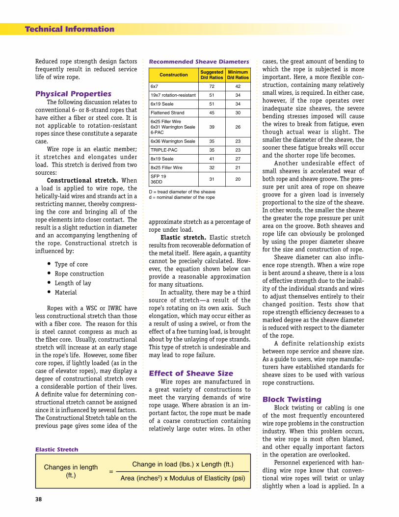
38
ASME Rules & GuidelinesTechnical Information
Reduced rope strength design factors frequently result in reduced service life of wire rope.
Physical Properties The following discussion relates to conventional 6- or 8-strand ropes that have either a fiber or steel core. It is not applicable to rotation-resistant ropes since these constitute a separate case. Wire rope is an elastic member; it stretches and elongates under load. This stretch is derived from two sources: Constructional stretch. When a load is applied to wire rope, the helically-laid wires and strands act in a restricting manner, thereby compress-ing the core and bringing all of the rope elements into closer contact. The result is a slight reduction in diameter and an accompanying lengthening of the rope. Constructional stretch is influenced by:
• Type of core • Rope construction • Length of lay • Material
Ropes with a WSC or IWRC have less constructional stretch than those with a fiber core. The reason for this is steel cannot compress as much as the fiber core. Usually, constructional stretch will increase at an early stage in the rope's life. However, some fiber core ropes, if lightly loaded (as in the case of elevator ropes), may display a degree of constructional stretch over a considerable portion of their lives. A definite value for determining con-structional stretch cannot be assigned since it is influenced by several factors. The Constructional Stretch table on the previous page gives some idea of the
approximate stretch as a percentage of rope under load. Elastic stretch. Elastic stretch results from recoverable deformation of the metal itself. Here again, a quantity cannot be precisely calculated. How-ever, the equation shown below can provide a reasonable approximation for many situations. In actuality, there may be a third source of stretch—a result of the rope's rotating on its own axis. Such elongation, which may occur either as a result of using a swivel, or from the effect of a free turning load, is brought about by the unlaying of rope strands. This type of stretch is undesirable and may lead to rope failure.
Effect of Sheave Size Wire ropes are manufactured in a great variety of constructions to meet the varying demands of wire rope usage. Where abrasion is an im-portant factor, the rope must be made of a coarse construction containing relatively large outer wires. In other
cases, the great amount of bending to which the rope is subjected is more important. Here, a more flexible con-struction, containing many relatively small wires, is required. In either case, however, if the rope operates over inadequate size sheaves, the severe bending stresses imposed will cause the wires to break from fatigue, even though actual wear is slight. The smaller the diameter of the sheave, the sooner these fatigue breaks will occur and the shorter rope life becomes. Another undesirable effect of small sheaves is accelerated wear of both rope and sheave groove. The pres-sure per unit area of rope on sheave groove for a given load is inversely proportional to the size of the sheave. In other words, the smaller the sheave the greater the rope pressure per unit area on the groove. Both sheaves and rope life can obviously be prolonged by using the proper diameter sheave for the size and construction of rope. Sheave diameter can also influ-ence rope strength. When a wire rope is bent around a sheave, there is a loss of effective strength due to the inabil-ity of the individual strands and wires to adjust themselves entirely to their changed position. Tests show that rope strength efficiency decreases to a marked degree as the sheave diameter is reduced with respect to the diameter of the rope. A definite relationship exists between rope service and sheave size. As a guide to users, wire rope manufac-turers have established standards for sheave sizes to be used with various rope constructions.
Block Twisting Block twisting or cabling is one of the most frequently encountered wire rope problems in the construction industry. When this problem occurs, the wire rope is most often blamed, and other equally important factors in the operation are overlooked. Personnel experienced with han-dling wire rope know that conven-tional wire ropes will twist or unlay slightly when a load is applied. In a
Elastic Stretch
htgnelnisegnahC).tf(
=).tf(htgneLx).sbl(daolniegnahC
sehcni(aerA 2 )isp(yticitsalEfosuludoMx)
noitcurtsnoCdetsegguSsoitaRd/D
muminiMsoitaRd/D
7x6 27 24
tnatsiser-noitator7x91 15 43
elaeS91x6 15 43
dnartSdenettalF 54 03
eriWrelliF52x6elaeSnotgnirraW13x6
CAP-693 62
elaeSnotgnirraW63x6 53 32
CAP-ELPIRT 53 32
elaeS91x8 14 72
eriWrelliF52x8 23 12
91PFSDD63
13 02
D = tread diameter of the sheaved = nominal diameter of the rope
Recommended Sheave Diameters

39
Technical Information
reeved hoisting system subjected to loading and unloading, such as a hoist line, this results in block twisting and possibly distortion of the wire rope. Cabling of the block most frequently occurs as the load in the wire rope is released and the falls are in a lowered position. Cabling may be considered as the twisting of the block beyond one-half revolution (180o twisting) of the traveling block. When this condi-tion occurs, the operator shows good judgement in not making additional lifts until the conditions causing the problem are corrected. The following machine and site conditions should be investigated for possible improvement in block twist-ing. 1. Reduce wire rope length. Longer rope lengths cause more twisting than short rope lengths. This applies particu- larly to the amount of wire rope in the fall. 2. Reduce the amount of load lifted. Heavily loaded ropes have more torque and twist than lightly loaded ropes. This condition would also apply to the speed of loading or shockloading, since this condition also causes higher wire rope loading. 3. Eliminate odd-part reeving where the wire rope dead end is on the traveling block. Wire rope torque, from the applica- tion of load, is greatest at the rope dead end. 4. Relocate the rope dead end at the boom in order to increase the separation be- tween the dead end and the other rope parts. This ap- plies a stabilizing load directly to the traveling block. The original equipment manufac- turer should be consulted before making this modification.
5. Increase sheave size. This increases the amount of separation between wire rope parts and may improve the situation by applying stabilizing loads and reducing the amount of rope torque transmitted to the traveling block. 6. Restrain the twisting block with a tag line. The use of rotation-resistant wire ropes will not likely be required unless the intended length of rope fall exceeds 100 feet, or the length of the hoist line exceeds 600 feet. In the event these latter conditions exist, the end user should anticipate using a combination of the rotation-resistant wire rope and the foregoing field suggestions.
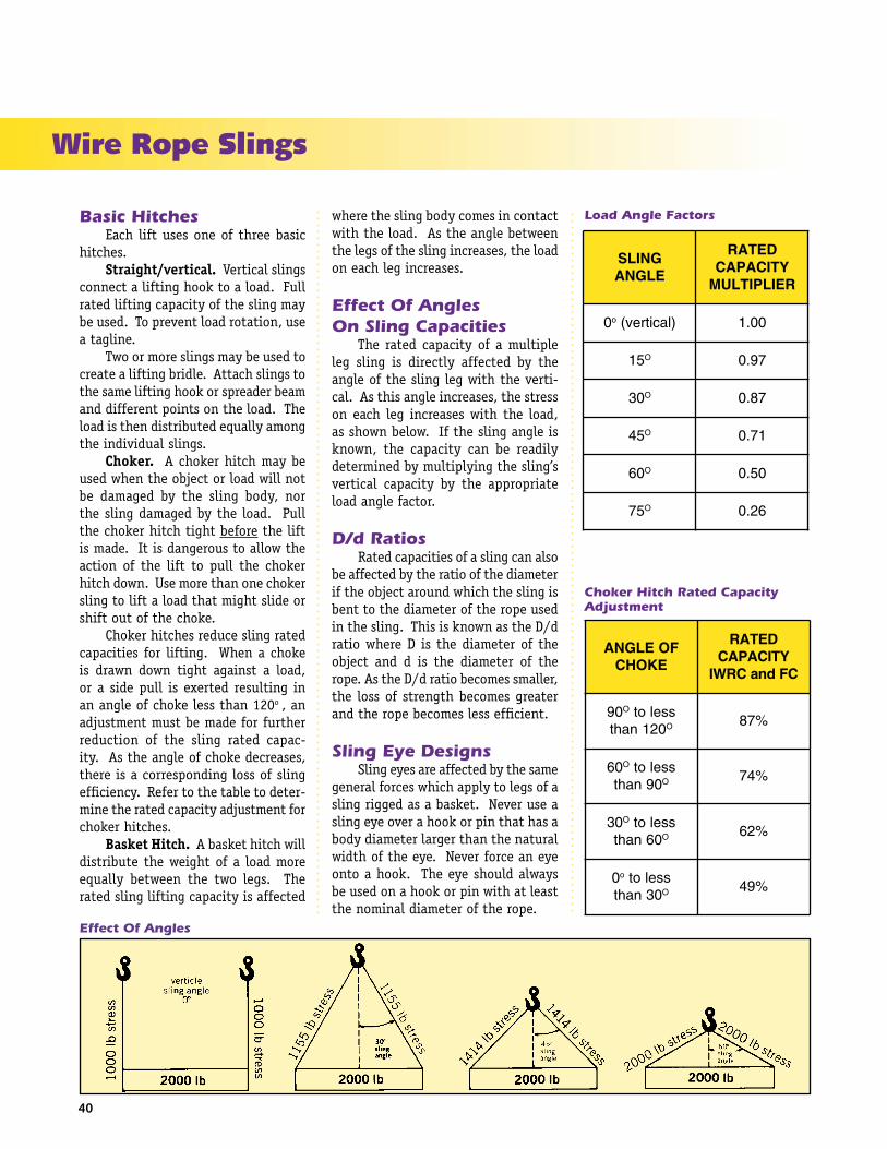
40
Wire Rope Slings
Basic Hitches Each lift uses one of three basic hitches. Straight/vertical. Vertical slings connect a lifting hook to a load. Full rated lifting capacity of the sling may be used. To prevent load rotation, use a tagline. Two or more slings may be used to create a lifting bridle. Attach slings to the same lifting hook or spreader beam and different points on the load. The load is then distributed equally among the individual slings. Choker. A choker hitch may be used when the object or load will not be damaged by the sling body, nor the sling damaged by the load. Pull the choker hitch tight before the lift is made. It is dangerous to allow the action of the lift to pull the choker hitch down. Use more than one choker sling to lift a load that might slide or shift out of the choke. Choker hitches reduce sling rated capacities for lifting. When a choke is drawn down tight against a load, or a side pull is exerted resulting in an angle of choke less than 120o , an adjustment must be made for further reduction of the sling rated capac-ity. As the angle of choke decreases, there is a corresponding loss of sling efficiency. Refer to the table to deter-mine the rated capacity adjustment for choker hitches. Basket Hitch. A basket hitch will distribute the weight of a load more equally between the two legs. The rated sling lifting capacity is affected
where the sling body comes in contact with the load. As the angle between the legs of the sling increases, the load on each leg increases.
Effect Of AnglesOn Sling Capacities The rated capacity of a multiple leg sling is directly affected by the angle of the sling leg with the verti-cal. As this angle increases, the stress on each leg increases with the load, as shown below. If the sling angle is known, the capacity can be readily determined by multiplying the sling’s vertical capacity by the appropriate load angle factor.
D/d Ratios Rated capacities of a sling can also be affected by the ratio of the diameter if the object around which the sling is bent to the diameter of the rope used in the sling. This is known as the D/d ratio where D is the diameter of the object and d is the diameter of the rope. As the D/d ratio becomes smaller, the loss of strength becomes greater and the rope becomes less efficient.
Sling Eye Designs Sling eyes are affected by the same general forces which apply to legs of a sling rigged as a basket. Never use a sling eye over a hook or pin that has a body diameter larger than the natural width of the eye. Never force an eye onto a hook. The eye should always be used on a hook or pin with at least the nominal diameter of the rope.
Effect Of Angles
Load Angle Factors
GNILSELGNA
DETARYTICAPACREILPITLUM
0o )lacitrev( 00.1
51 O 79.0
03 O 78.0
54 O 17.0
06 O 05.0
57 O 62.0
FOELGNAEKOHC
DETARYTICAPACCFdnaCRWI
09 O sselot021naht O %78
06 O sselot09naht O %47
03 O sselot06naht O %26
0o sselot03naht O %94
Choker Hitch Rated Capacity Adjustment

41
Wire Rope Sling Inspection An exact determination of when to retire a sling depends on many variables, and limited federal guidelines exist. Rather sling retirement (and safety factors) must be left to the judgement of a trained and experienced professional who is capable of evaluating remaining strength in the sling. Proper allowance must be made for deterioration as disclosed by inspection. The safety of an operating sling depends upon this remaining strength. The following conditions must be taken into account when determining the safe operating condition of a sling.
1. For strand laid and single part slings, ten randomly distributed wires on one rope lay, or five broken wires in one strand in one rope lay. 2. For cable laid and braided slings of less than eight parts, twenty randomly distributed broken wires in one lay or braid, or one broken strand per sling 3. For braided slings of eight parts or more, forty randomly distributed wires in one lay or two broken strands per sling 4. Severe localized abrasion or scraping. 5. Kinking, crushing, bird caging or any other damage resulting in distortion of the wire rope.
Wire Rope Slings
RecommendedOperating Practices Whenever any sling is used, the following practices must be observed. 1. Destroy retired slings. 2. Never expose slings to tempera- tures in excess of the manufac- turer’s recommendations. 3. Use a sling that is long enough to provide the minimum practi- cal vertical angle. 4. Never shorten a sling with knots, bolts or other methods. 5. Never twist or kink the legs of a sling. 6. Never load a sling in excess of its rated capacity. 7. Center the load in the base (bowl) of the hook to prevent point loading. 8. When using a basket hitch, balance the load to prevent slippage. 9. Always protect slings from sharp edges. 10. Securely hitch each sling to its load. 11. Avoid shockloading. 12. Never pull a sling from under a load while that load is resting on the sling. 13. Never use homemade fittings and attachments. 14. Never make a sling from used wire rope. 15. Never use any sling that is of questionable strength and condition.
6. Evidence of heat damage: if a wire rope sling having a fiber core is exposed to temperatures in excess of 200o F; or if a wire rope sling having an IWRC is used at temperatures above 400o F or below -60o F. 7. End attachments that are cracked, deformed or worn. 8. Hooks that have been opened more than 15% of the normal throat opening measured at the narrowest point more than 10o
from the plane of the unbent hook. 9. Corrosion of the rope or end attachments.

42
ASME Rules & GuidelinesWire Rope Slings
No. 105-B With Torpedo Loop-lock SplicesSingle-leg sling with standard Flemish eye mechanical splice, secured with steel sleeves.
.MAIDSEHCNI
HTGNELNIM)LS(
GNILSFO)sehcni-teef(
POOLSNOISNEMID
).sbl000,2(SNOTNISEITICAPACDETAR
CRWI)PIE(SULPELPRUP
W)ni(
L)ni(
REKOHC LACITREV
HCTIHTEKSAB)lacitrevotseerged(
06 O 54 O 03 O
4/1 6-1 2 4 84.0 56.0 56.0 19.0 01.1
8/3 2 3 6 01.1 04.1 04.1 00.2 05.2
2/1 6-2 4 8 09.1 05.2 05.2 06.3 04.4
8/5 3 5 01 09.2 09.3 09.3 05.5 08.6
4/3 6-3 6 21 01.4 06.5 06.5 09.7 07.9
8/7 4 7 41 06.5 06.7 06.7 00.11 00.31
1 6-4 8 61 02.7 08.9 08.9 00.41 00.71
8/1-1 5 9 81 01.9 00.21 00.21 00.71 00.12
4/1-1 6-5 01 02 00.11 00.51 00.51 00.12 00.62
8/3-1 6 11 22 00.31 00.81 00.81 00.52 00.13
2/1-1 7 21 42 00.61 00.12 00.12 00.03 00.73
4/3-1 8 41 82 00.12 00.82 00.82 00.04 00.94
2 9 61 23 00.82 00.73 00.73 00.25 00.36
tcatnocdaolfotniopehttaerutavrucforetemaidmuminimanodesaberasehctihteksabfoseiticapacdetaRsgnilsrofretemaideporehtsemit52dna,retemaid"1hguorht"4/1sgnilsrofretemaideporehtsemit04fo
.regraldnaretemaid"8/1-1

43
Construction andIndustrial Applications• Standard 6x19 and 6x36 classes
• Standard rotation-resistant ropes in 8x19, 8x25, 19x7 constructions
• Specialized rotation-resistant ropes SFP-19
• 6-PAC and 6-PAC RV
• Triple-Pac EEEIP crane rope
• BXL plastic-infused wire rope
• Roepac compacted wire rope
• Alternate lay wire rope
Oil Field Applications• Rotary drill lines
• Tubing lines
• Sand lines
• Well measuring line
• Well servicing line
• 6x25 flex seale tubing line
• 6-Pac tubing line
• Flattened strand rope
Elevator Applications• 6x19, 8x19, and 9x19 classes for hoist, governor and compensating rope applications
Logging Applications• Standard 6x19 and 6x36 Classes
• Super-B
• Super-PAC
• 6-PAC
• BXL
• SKYBRITE
Mining Applications• Standard 6x19, 6x36, 6x61, 6x70, 8x19 and 8x37 Classes
• Boom pendants
• Flattened strand rope
• En-Core plastic encapsulated core for drag ropes
• Bethpac compacted wire rope
• Maxi-Core IWRC
• BXL plastic-infused rope
• Phoenix specially-designed hoist ropes
Ocean Cable Systems• Anchor/mooring systems
• Galvanized torque-balanced spiral strand, bare or sheathed, with or without Z-nodes
• Galvanized wire rope, with or without Z-nodes
WW manufactures a complete line of Bethlehem Wire Rope up to 7" diameter and structural strand products up to 6" diameter, as well as various wire products. Contact WW’s customer service department for further information on these and other products.
Standard Products List
Bethlehem Wire Rope Service Centers
California: Compton
Illinois: Chicago
Indiana: Boonville
Oklahoma: Oklahoma City
Oklahoma: Woodward
Missouri: St. Louis
Pennsylvania: Williamsport
Texas: Houston
Texas: Odessa
Washington: Seattle

Manufacturer of
Bethlehem Wire Rope®
100 Maynard StreetWilliamsport, PA 17701 USA
Tel: 570-326-5146 International1-800-541-7673 Inside the U.S.
Fax: 570-327-4274www.wireropeworks.com
Wirerope Works, Inc.