best practices guide for residential hvac retrofitsseedengr.com/documents/retrofittinghvac.pdf ·...
TRANSCRIPT

B E S T P R A C T I C E S G U I D E F O R R E S I D E N T I A L H VA C R E T R O F I T S
INTRODUCTION
This best practices guide for residential HVAC system retrofits is aimed at contractors who want guidance on delivering energy efficient, cost effective and innovative products. It has been developed around the idea of having packages of changes to the building HVAC system and building envelope that are climate and house construction dependent. These packages include materials, procedures and equipment and are designed to remove some of the guesswork from a builder, contractor, installer or homeowner decisions about how best to carry out HVAC changes. The packages are not meant to be taken as rigid requirements – instead they are systems engineered guidelines that form the basis for energy efficient retrofits. Similar approaches have been taken previously for new construction to develop extremely energy efficient homes that are comfortable safe and durable, and often cost less than standard construction. This is best epitomized by the Building America program whose partners have built thousands of residences throughout the U.S. using these principles. The differences between retrofitting and new construction tend to limit the changes one can make to a building, so these packages rely on relatively simple and non-intrusive technologies and techniques. The retrofits also focus on changes to a building that will give many years of service to the occupants. Another key aspect of these best practices is that we need to know how a house is working so that we know what parts have the potential for improvement. To do this we have put together a set of diagnostic tools that combine physical measurements and checklists/questionnaires. The measured test results, observations and homeowner answers to questions are used to direct us towards the best retrofits applicable to each individual house. The retrofits will depend on the current condition of the building envelope and HVAC system, the local climate, the construction methods used for the house, and the presence of various energy saving systems (e.g., a Heat Recovery Ventilator) and/or materials. This is just like a doctor referring a patient for blood tests or x-rays before actually performing surgery. This way the doctor can be sure that he does the right thing. To take this analogy further – we can borrow from the medical profession and say that the first thought when retrofitting a house is to do no harm, i.e., do not make changes that could make the house worse to live in. This guide was developed in conjunction with input from many members of the HVAC industry and research community. Thanks to all those who participated.
1
WHEN DO WE GET ACCESS TO AN EXISTING HOME?
REPAIR
When the HVAC system is not working is usually the first time a homeowner has any interest or awareness of the HVAC system in the house. Because of the catastrophic nature of repair calls and the short time allowed for repair (particularly unheated homes in cold winter climates) – prepared packages are essential because there is little time to analyze an individual home to determine optimum retrofits. Often equipment is broken and this is an ideal time to suggest replacement, together with other related upgrades from the retrofit packages.
REPLACEMENT
Some homeowners will have consistent maintenance programs for their HVAC systems (e.g., spring tune-ups for air conditioners) and will be aware that it is better to replace equipment before it fails in an emergency situation. Homeowners may also want to upgrade/improve their HVAC systems, in some cases to increase energy efficiency if they have high bills or if their utility offers rebate programs. When equipment is replaced, this is another key time to use the systems engineering approach to look at building and HVAC components beyond the furnace or compressor.
REMODEL
When homes are remodeled, HVAC systems are often upgraded so that they can better condition the house and changing use of rooms, or their capacity is increased if the remodel includes the addition of rooms. Because remodeling often includes removal of floors and walls this allows more extensive retrofits – like replacing all ducts or completely redesigning the duct system to make it smaller or run inside conditioned space. Because of the high disruption level associated with remodeling, location of air handlers, outdoor condensers and installation of economizers will also be easier. MOLD REMEDIATION Significant problems with mold are becoming more common and a mold remediation program needs to include methods of keeping the house mold-free after the immediate problem is solved. This requires a combination of fixing problems with the building envelope (e.g., installing flashing, fixing roof leaks, sealing crawlspaces, etc.) and having a space conditioning system that controls indoor temperature and humidity. The solutions can be very complex for the building envelope, involving more/better insulation, better drying potential, when to use vapor barriers and when not to use them, adequate ventilation, etc., and these issues are beyond the scope of this guide that focuses on HVAC issues. However, the HVAC system can be used to control some mold related problems and only a correctly sized and well designed and installed HVAC system will provide the correct temperature control, ventilation and humidity removal required to prevent re-occurrence of indoor air related mold problems.
OPPORTUNITIES
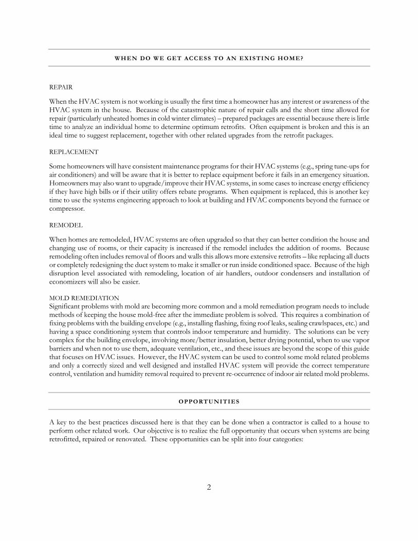
A key to the best practices discussed here is that they can be done when a contractor is called to a house to perform other related work. Our objective is to realize the full opportunity that occurs when systems are being retrofitted, repaired or renovated. These opportunities can be split into four categories:
2
System upgrades. Rather than replace a system with one of the same energy efficiency we can encourage the use of higher efficiency equipment. In addition the system can have many added features that ensure increased comfort, safety and durability in addition to reduced energy use. Examples include:
• Correctly sized and/or multiple speed heating or cooling equipment to better match building loads.
• Added economizers to provide ventilation and reduce electricity consumption by reducing air conditioner energy use.
• Added zoning to increase comfort. This is particularly useful in houses that have large areas that are poorly conditioned. A classic example is a single-zone two-story house that is always warmer upstairs whether heating or cooling.
• Improved room airflow for more uniform temperatures in a room. • Better controllers, for example programmable thermostats, or using humidity rather than
temperature control in humid climates. • An operators manual, so that homeowners can get the most out of their HVAC system and know if
things are going wrong. Sizing. If the duct system is improved with increased insulation and reduced leakage, and/or we also reduce building loads through envelope changes, then the system can be downsized. Additionally, most residential systems are already oversized and would benefit from correct sizing to reduce cyclic losses and improve part load humidity control. There are limits on downsizing. For example, downsizing the equipment significantly without resizing the ducts could result in air balancing and register throw problems. Integrated systems. An important aspect of healthy, durable and safe homes is to provide proper levels of ventilation. However, to ensure that ventilation is provided in an energy efficient manner it is important to integrate the ventilation and heating/cooling systems. There are many opportunities here, but the key ones are that ventilation air can be heated, cooled, filtered, humidity controlled and distributed evenly through out the house using the forced air thermal distribution system. If there is no forced air system, then it can be a good idea to include a small scale air distribution system using small diameter pipe inside the conditioned space (in wall and floor cavities). Due to small total air flows required for ventilation the ducts can be of small diameter. In addition, simple exhaust or supply fans without distribution systems can be integrated into the rest of the HVAC system, for example, through controls that run the central air handler fan to distribute fresh air. These simple systems are usually integrated with the central HVAC system unintentionally because the HVAC system ducts provide air flow pathways through out the house so that simple exhaust or supply fans can draw air from many locations via the duct system. Door undercuts and transfer grilles (or ducts) are also flow paths for air to flow from a room to a central exhaust or supply location and they should be considered part of the central HVAC system.
Mold and odor reduction. A properly designed and installed HVAC system can remove the problems caused by high indoor air humidity and the resulting condensation, mold and odor issues.
RETROFIT SELECTION GUIDE
The selection of appropriate retrofits is determined by using this guide. The guide uses a screening technique to evaluate the building and compares the test results to target values so that retrofit decisions can be made. The target values were chosen to represent levels of performance that we could reasonably expect existing buildings to reach, rather than the absolute best values that might be more appropriate for new construction. In addition to
3

determining the potential retrofit possibilities it is important to commission the retrofits during installation to ensure that the retrofits perform as intended. The commissioning process uses the same diagnostic tests as the screening technique. The screening is broken down into the following sections, all of which are required to provide the systems based approach of this guide:
• Climate • Diagnostic Measurements • Moisture • Screening checklist • Sizing
The results of the screening are entered into the checklist and the actual values are compared to target values. When targets are not met, then the potential retrofit action needs to be taken.
4

SCREENING CHECKLIST
Measurement/Observation
Potential Target value Potential Retrofit Action
Duct leakage <10% of air handler flow Seal ducts: aeroseal/tape/mastic Duct insulation R6 (RSI 1) to R8 (RSI 1.4) for all ducts outside
conditioned space Add insulation to ducts
Air flows at registers Compare to ACCA manual J Replace registers, open/close dampers, reduce system flow resistance by straightening existing ducts or replacing them with straight runs of new ducts.
Air handler flow Cooling: >400 cfm/ton in dry climate, or >350 cfm/ton in humid climate Heating: 12.5 cfm/kBtu/h
Replace filters, fix duct restrictions, change fan speed, replace fan with high efficient unit, add extra returns in return restricted systems
Filter Condition Clean and at least MERV 61 Replace with MERV 6 or better. Use 2 or 4 inch filters if possible
Thermostat Setting Heating: 68°F (20°C) Cooling: 78°F (25°C) Thermostat raised in summer and lowered in winter to account for better distribution, mixing and envelope improvements.
Spot ventilation 50 cfm each bathroom 100 cfm each kitchen
Replace fans, fix restrictive ducting
Spot Ventilation fan power consumption
2.5 cfm/W (1.2 L/s/W). A good source for these ratings is the HVI directory (www.hvi.org)
Replace with higher efficiency unit, remove/reduce duct flow restrictions, clean fan and ducting
Equipment capacity Manual S Replace with correct size Refrigerant charge Use superheat or subcooling tests Add/subtract refrigerant Age and Condition of HVAC system
Clean and undamaged. Determine system age.
Clean the system and repair damage or Replace the system if > 15 years old
Location of HVAC system equipment and ducts
Inside conditioned space Seal and insulates duct locations to make them more like conditioned space, or move system location.
Window A/C units EnergyStar compliant Replace with central unit or improved distribution Multiple systems/zoning System and controls in good working order and
providing good comfort for occupants Ensure correct damper operation, check capacity of each system/zone matches a Manual J (or equivalent) load calculation
Envelope leakage Normalized Leakage Area reduction of 0.35 Insulate envelope, seal windows/doors/other openings Moisture testing No moisture problems Source control – better kitchen and bath venting, fix
flashing/detailing, seal crawlspaces in high humidity climates, replace windows, add insulation to walls, floors and ceiling
House insulation Ceiling: R-30 (RSI 5.3) minimum, R-49 (RSI 8.6) in cold/severe cold climate. Floor over crawlspace:R- 25 (RSI 4.4). Basement walls: R10 (RSI 1.8), Basement Floor or slab usually depends on local codes. Walls: Cavity should be completely filled with insulation.
Add insulation to fill cavity. Add semi-permeable rigid exterior insulation in cold/severe cold climates if the wall is 2×4 construction.
Windows Double-glazed, low-e. Shaded in cooling dominant climates
Replace windows. Add shading.
Window shading Located on south and/or west facing windows Add shading to reduce solar loads Solar radiation control Radiant barrier in attic, low absorbtivity roof
coatings Add radiant barrier in attic, or low absorbtivity roof coatings
Wall, floor and ceiling construction
Space for ducts/vents
Evaluate house energy bills (if available)
Occupant survey Ask occupants to report problems
No problems Moisture removal strategies, new windows, change register type, airflow and location to improve mixing/remove drafts, add envelope insulation, etc.
Return to Selection Guide 1 MERV is an industry standard rating system for air filters, it stands for Minimum Efficiency Report Value determined using ASHRAE Standard 52.2
5

CLIMATE
The climate limits the range of retrofits that can be applied to a house. Collaboration between DOE (PNNL) and Building Science Corp. has led to the development of several climate zones for the U.S. and Canada that are based on temperature and humidity conditions. For more specific climatic variations it is recommended that more detailed tools are used, for example: DOE’s Home Energy Saver (homenergysaver.lbl.gov) and the Energy Star Home Improvement Toolbox (http://208.254.22.7/index.cfm?c=home_improvement.hm_improvement_index).
From Building Science Corporation
Return to Selection Guide
6

SCREENING DIAGNOSTIC MEASUREMENTS
DUCT LEAKAGE
An ideal duct system would have no duct leakage, however, the components, materials and installation techniques used for residential systems have led to most systems having significant leakage. Sealing these duct leaks is a key aspect of any HVAC retrofit because the energy savings can be significant for ducts outside conditioned space (typically about 20%). In addition, the system delivers more of its conditioned air to the conditioned space instead of losing it to the duct surroundings that allows the use of reduced capacity equipment. There are a couple of methods of duct leakage testing that are recommended (and are described in detail in ASTM Standard E1554): duct pressurization and the DeltaQ method. In either case the target is to have total duct leakage be less than 6% of air handler flow.
Ducts are usually sealed using manual techniques using mastic or tape products. Cloth-backed rubber adhesive tape (i.e. Normal duct tape) should not be used. These techniques tend to be labor intensive, and require a well-trained and motivated work crew. In particular, training needs to focus on showing how to find leaks using smoke sticks or register flow diagnostics, and paying particular attention to duct connections. Completely disconnected ducts are surprisingly common and should be the first priority when sealing duct systems. An alternative to mastic and tape products is to use an aerosol sealing system.
-4000
-3000
-2000
-1000
0
1000
2000
3000
4000
-60 -40 -20 0 20 40 60
Envelope Pressure Difference(Pa)
Blo
wer
Doo
r Fl
ow (
cfm
)
-200
-150
-100
-50
0
50
100
150
200
Del
taQ
Flo
w D
iffer
ence
(cfm
)
Air Handler ONAir Handeler OffDeltaQ
The DeltaQ test uses a blower door to perform building pressurization with the air handler on and off to determine duct leakage and envelope leakage at the same time. This figure illustrates an example DeltaQ test.
Duct pressurization uses a combined fan/flowmeter to pressurize a duct system to measure the flow through the leaks at fixed conditions
AIR FLOWS AT REGISTERS
Having the correct air flow at a register means that the HVAC system will be able to keep the room comfortable. Target airflows should be based on engineering calculations using standard techniques such as those published in Air Conditioning Contractors of America (ACCA) Manual J. Measuring air flows at registers also helps to find disconnected ducts. Residential register air flow techniques range from the use of complex (but highly accurate) powered flow hoods, to simply timing how long it takes to fill a plastic bag. For system balancing, detecting
7

disconnects or setting register flows, most of these techniques are acceptable (for a more thorough discussion of these measurement techniques see http://epb1.lbl.gov/EPB/Publications/lbnl-47382.pdf). Note that most commercially available flow hoods are not accurate enough in residential applications, and something simple like bag filling is preferable.
Basket flow meter Powered Flow Hood Bag filling
Various methods of measuring air flow at registers
AIR HANDLER FLOW
Air handler flows need to be checked because systems with too low a flow (<350 cfm/ton of cooling or <10cfm/kBtu/h for heating) tend to have poor efficiency for cooling or too high duct temperatures for heating (that lead to excessive conduction loses, furnaces operating on high limit switches and dangerously hot furnaces and plenums). The reason that system air flows tend to be too low is that installers (and equipment manufacturers) underestimate the flow resistance of the system. The system flow resistance tends to be high due to the use of flexible ducts that have high flow resistance (particularly if not stretched tight on installation), undersized ducts, and dirty filters and coils. However for cooling systems in humid climates, the air flow may be set deliberately low despite the associated energy efficiency penalty in order to increase the latent capacity of the equipment. At the other end of the air flow scale, systems with too high flow will tend to have noise problems. Air handler flows should be measured using standard techniques such as pressure matching using an auxiliary fan and flowmeter or flow plates inserted into the system (for more details see ASTM E1554, ASHRAE Standard 152 and Appendix F of California Title 24 (http://www.energy.ca.gov/title24/residential_acm/residential_acm.PDF)). Variable speed air handler fans present a great challenge because their typical operating conditions are generally unknown and poorly defined. This means that field technicians need to thoroughly understand how these systems operate and how to ensure that fan speeds do not change during diagnostic measurements. In some cases it may be desirable to operate the system in multiple modes so as to evaluate the air handler flow at different system operating modes.
8

Pressure matching using an auxiliary fan and flowmeter Flow plate used to measure air handler flows (Paul Francisco, ECOTOPE, Inc.)
EXHAUST AND SUPPLY FAN FLOW
Exhaust and supply fans in existing houses often have poor air flow due to bad installation (often the ducting to outside is convoluted resulting in excessive flow resistance and low air flows) and accumulated dirt. Common complaints are low airflow and excessive noise. The power consumption of these fans varies widely and it is often the low airflow noisy fans that use the most power. These fans can be replaced with quiet, efficient fans that move the correct amount of air for their application. The Home Ventilating Institute recommends 15 Air Changer per Hour (ACH) for kitchens and 8 ACH for bathrooms. ASHRAE Standard 62.2 recommends 5 ACH and 20 cfm (10 L/s) for continuous exhaust and 100 cfm (50 L/s) for kitchens and 50 cfm (25 L/s) for bathrooms for intermittent exhaust. Typical bathroom exhausts have air flow rates between 50 and 100 cfm (25 and 50 L/s). Kitchen range hoods are usually rated at much higher air flow rates (up to 1200 cfm (600 L/s)). The Home Ventilating Institute recommends 40 cfm per linear foot of range hood perimeter. Note that the higher airflow kitchen vent fans may cause severe building depressurization that may result in combustion appliance or fireplace backdrafting, or excessive outdoor air leakage through the building envelope that can lead to moisture problems and higher heating and cooling loads. Consider replacing very high airflow (>500 cfm (250 L/s)) kitchen exhausts with lower airflow fans if you think some of these conditions may occur.
Some houses have attic ventilation systems that either blow air from the house into the attic, sometimes referred to as “whole house” ventilators. These systems tend to have extremely high air flows, with rated flow up to 7000 cfm. As with the higher air flow kitchen fans, caution needs to be taken when depressurizing houses with air flow this high. Other attic venting systems exchange air with outside instead of the house. The attic ventilators tend to have airflow in excess of 1000 cfm (500 L/s).
Published directories (e.g., the Home Ventilating Institute (www.hvi.org)) of fan performance include rated air flow, and noise and power consumption in some cases. In some houses there may be more complex ventilation
9

systems, such as heat recovery ventilators, that are also prone to the same problems. Measuring the flows from these exhaust and supply fans can be accomplished using the same methods as used for air flows at registers.
REFRIGERANT CHARGE
Refrigerant charge has an optimum level for best efficiency and capacity. Both over and under charging can reduce system performance, but undercharging is most common. In severe cases poor system charge can lead to equipment failure. Refrigerant charge can be estimated using standard industry test procedures: superheat, subcooling or approach methods – depending on the manufacturers recommendations for an individual piece of equipment. One difficulty with these methods is that they cannot be performed in extremely dry weather or when it is cold outside This is primarily an issue when installing systems in winter months when they cannot be tested. In those cases, the system needs be tested in the spring before the first time the air conditioner would operate that year. When evaluating an existing system there are other indicators of charge problems – such as frozen indoor evaporator coils – that can be used as diagnostic tools.
ENVELOPE LEAKAGE
Most houses in the US have leaky building envelopes that result in too much air infiltration, uncomfortable drafts, and high energy bills. Reducing the infiltration load by sealing the envelope reduces the required HVAC equipment capacity and improves occupant comfort. For many years weatherization programs have worked at sealing building envelopes to cure these problems. Envelope leakage is measured using standard pressurization techniques (e.g., ASTM E779, ASTM E1827, and various fixed pressure flow requirements from weatherization programs). Surveys have shown that good envelope sealing typically reduces Normalized Leakage (NL) by 0.35. NL is a method of accounting for the size of house in terms of its floor area and height when comparing envelope leakage between houses. The envelope leakage area is normalized by the floor area and eave height relative to that of a one-story house. For energy purposes, NL is a convenient metric because it approximately represents the seasonal average air change rate due to natural infiltration alone. For an airtight one-story house, a normalized leakage of 0.1 is approximately equivalent to 2.1 ACH50 or an effective leakage area of 1.4 in2/100 ft2 (SLA=1.0). An NL of 0.1 for a two-story house is approximately equivalent to 1.7 ACH50 or an effective leakage area of 1.2 in2/100 ft2 (SLA=0.8). Using the same NL regardless of house height ensures that different height houses are on a level playing field in terms of energy consumption associated with infiltration. It also means that taller houses need to be more airtight.
10
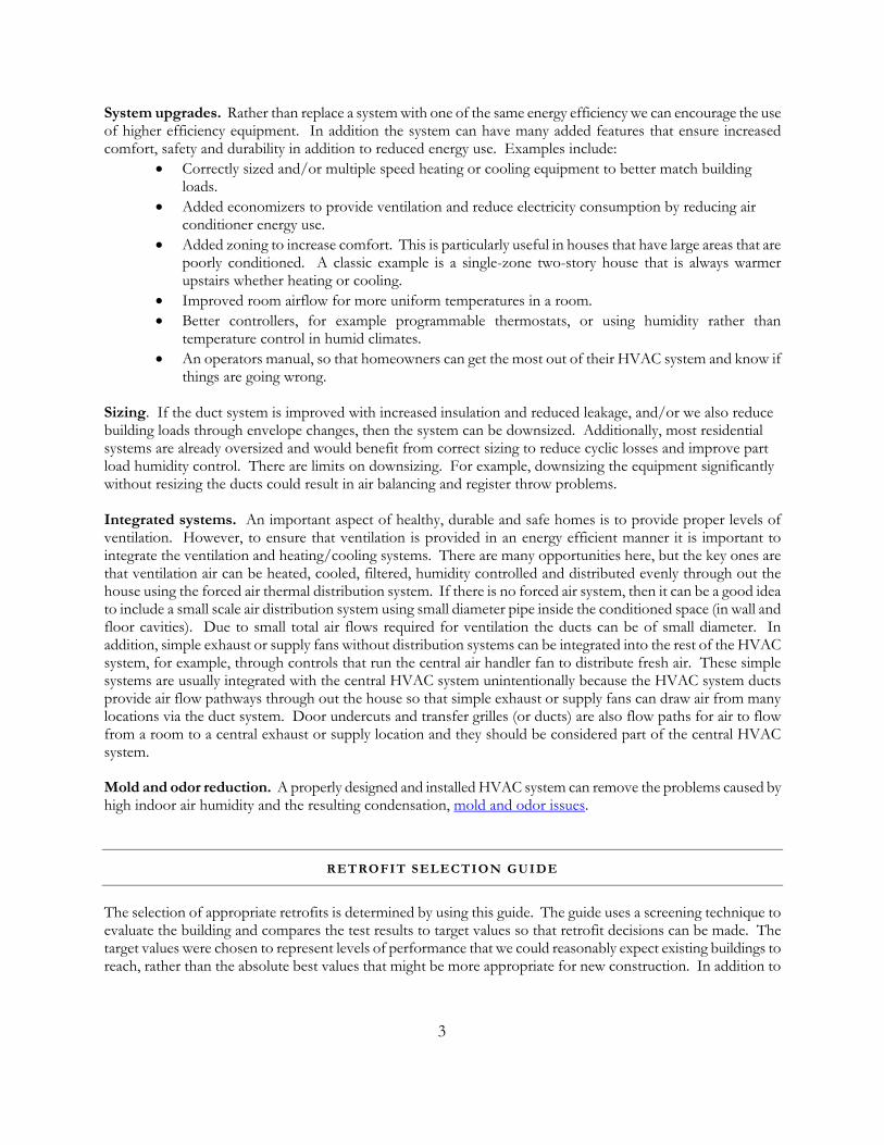
Other codes and standards (ASHRAE standards (119 and 136) and the California State Energy Code (Title 24)) discuss appropriate levels of envelope leakage. When tightening existing building envelopes, caution must sometimes be used so as not to introduce moisture problems. Older houses with leaky, uninsulated wall cavities can have reduced moisture problems because the large air flows allow the wall cavities to dry. When these air flows are reduced – this drying potential is also reduced. It is a good idea to ensure that the possibility of rain penetration is minimized by examining the exterior of the building envelope – particularly around doors, windows, and plumbing and electrical penetrations.
Using a blower door to perform a pressurization test on a building envelope
Envelope sealing: Often there are large building cavities or chases that are open to outside via attics, crawlspaces or garages. This is an example of a sealed chase viewed from the attic. The large white rectangles are duct board insulation that has been used to block off large open areas
.
11

Envelope sealing: Other leaks have much smaller dimensions – often they are just cracks, and are best sealed using foam
Return to Selection Guide
MOISTURE
Visual Inspection/Odor Visual observation of wetness, mold/mildew, color/texture, and dimensional/structural problems combined
with odor are the standard techniques for finding moisture problems. Note that these techniques are good for existing problems but cannot evaluate the potential for future problems. One of the objectives of the retrofit packages is to have HVAC systems that are good at controlling indoor air moisture to reduce condensation on cool indoor surfaces. Windows in cold climates tend to be a major source of liquid water due to condensation that leads to mold growth on window surfaces and in extreme cases to rotting of window sills. Cold slabs are another condensation site that can lead to health issues due to mold growth and dust mites, particularly in carpet placed over cold concrete slabs. Pressure imbalances due to duct leakage can force moisture laden air into building envelopes and lead to moisture problems, and fixing duct leakage can minimize this problem. Many building envelope moisture problems are due to water leakage from outside rather than excessive indoor humidity. In these cases it is essential to find the leaks and fix them because one cannot rely on indoor humidity control to prevent envelope damage from these leaks. Lastly, envelope penetrations related to HVAC systems for electricity, gas and refrigerant lines, condensate drains, combustion air, flues, and outside air ducts need to be carefully sealed to prevent moisture entry.
12

Extreme moisture problems lead to wood rot and fungal growth
Less extreme is this typical condensation in single pane windows
Electrical Inspection For Moisture Impedance scanning and conductance probing can be used to detect subsurface problems before they are visually apparent. The target moisture readings depend on the specific material being tested. For example, for wood and wood products moisture levels below 20% are desirable.
Two inspection agencies have recently developed diagnostic protocols for moisture inspection ((NHCID 1998, GAHI 2000). These protocols address water damage that has occurred in southeastern US houses clad with Exterior Insulation and Finish Systems (EIFS).
The NHCID (New Hanover County Inspection Department) protocol is the most developed one available. It provides guidelines for locating and assessing moisture related damage in wood frame structures clad with drainable EIFS. It describes the use of a dielectric moisture meter for qualitative investigation, followed by subsequent quantitative assessment of suspected wet areas with a conductance meter. It also describes locations for wall scanning and probing, including below windows, doors, flashing, penetrations, and joints. In addition, it provides a comprehensive reporting format to document measurements. This protocol contains no precision and bias specifications, but it does suggest a field method for “calibrating” a dielectric meter.
The GAHI (Georgia Association of Home Inspectors) protocol provides brief guidelines and recommendations for visually inspecting and testing houses clad with EIFS. The visual inspections focus on observing exterior water
13

damage, as well as assessing exterior water drainage and intrusion management systems. It recommends that visual observations suggesting water entry be followed by moisture testing using a dielectric meter and then a conductance meter. It suggests conducting destructive structural investigations if moisture contents greater than 30% are measured. A related document (EIMA 2000) is largely based on the GAHI protocol. Its visual inspections focus on observing interior water damage, as well as assessing exterior water drainage and intrusion management systems. The EIMA (EIFS Industry Members Association) protocol requires only a conductance meter. It suggests conducting destructive structural investigations beginning at a lower threshold: 20%. The EIMA protocol also provides a cursory form as guidance for recording inspection data.
Return to Selection Guide
SCREENING CHECKLIST
DUCT INSULATION
For flexible duct, the insulation level is often printed on the outer jacket. Otherwise insulation levels have to be estimated from the thickness and insulation type. A minimum of R8 (RSI 1.4) is required for ducts outside conditioned space. Most ducts will require additional insulation to get to this level of insulation. Other than replacing ducts with new insulated ducts, the commonest method is to apply a duct wrap of glass fiber insulation. Other alternatives include burying ducts in blown-in insulation – either restrained by cardboard forms or as part of additional envelope insulation (e.g., insulation added to attic floors when ducts are lying on the attic floor). The duct insulation should include an airtight exterior vapor barrier to reduce the chance of condensation on cold duct surfaces in humid cooling climates.
LOCATION OF DUCTS, AIR HANDLER FAN, PLENUMS, AND HEAT EXCHANGR/COOLING COIL
The location of these components has a significant effect on ease of access and potential for adding economizer and ventilation ducting to the system. Space restrictions can also limit the size of replacement components. As much as possible, the system should be brought inside the conditioned space. If located in the attic, then considerable system performance improvements can be had by improving the attic: by adding radiant barriers (in predominantly cooling climates) or sealing and insulating to make it an unvented attic. Similarly, when ducts are in crawlspaces the crawlspace can be sealed and insulated. Note that sealing crawlspaces must include ground cover to reduce moisture and radon entry. In addition, some sealed crawlspaces use an exhaust fan to depressurize the crawlspace relative to the house to prevent transport of moisture, radon and other pollutants from the crawlspace to the house.
LOCATION OF OUTDOOR A/C UNIT
Often outdoor air conditioning components are poorly sited. Issues include excessive refrigerant line length and poor physical support.
14

A good candidate for replacement: an old condensing unit showing poor condition of unit (heavily corroded
sheet metal and fasteners and significant dirt/dust blocking flow into coil) and subsided slab (that we believe led to stresses on refrigerant lines with a subsequent leakage of refrigerant – this system had too little charge)
AGE AND CONDITION OF HVAC SYSTEM
A simple evaluation of the age and visual appearance of the HVAC system can be a good indicator for retrofitting. An older system will almost certainly be less efficient than newer equipment and the degradation of air seals and flue systems with age present good candidates for retrofitting. A system that shows dirty, rusting sheet metal, missing duct tape, missing fasteners, dust marked open face insulation, poor alignment of flues or air ducts, missing flues or air ducts, missing insulation, etc., is showing signs of neglect and is a good candidate for retrofitting or replacement.
60.0
65.0
70.0
75.0
80.0
85.0
1970 1975 1980 1985 1990 1995 2000 2005
Year
Ave
rage
AFU
E
6.00
7.00
8.00
9.00
10.00
11.00
12.00
1950 1960 1970 1980 1990 2000 2010
Year
Ave
rage
SE
ER
15

Historic values of Furnace (AFUE) and Air Conditioner (SEER) Efficiency sold in each year
OCCUPANT SURVEY
Ask occupants to report problems (comfort, high bills, condensation, mold etc.). Guidelines for evaluating energy bills can be found at DOE’s Home Energy Saver (homenergysaver.lbl.gov) and the Energy Star Home Improvement Toolbox (http://208.254.22.7/index.cfm?c=home_improvement.hm_improvement_index). Ask occupants about important lifestyle activities that can significantly change building loads and the times that the house needs to be conditioned. The following are some typical questions that should be asked:
• How many people live in the house? More occupants indicate that the chances for humidity and other IEQ problems will be greater (therefore a tight house envelop will require the addition of mechanical ventilation).
• Are there any pets? Like human occupants, pets are a source of moisture and odors. This means that adequate ventilation is required – with more ventilation required for more or larger pets. Fishtanks are a source of humidity – particularly if they are large and/or uncovered. Exotic pets may have particular temperature and humidity requirements that make for unusual building loads – check with the homeowner.
• How often do you cook at home? Cooking at home (particularly if using a gas range) introduces more pollutants and will require the use of a good range hood that vents to outside.
EVALUATE HOUSE ENERGY BILLS
Not surprisingly, high energy bills can be a good indicator of HVAC system problems, and the potential to perform envelope upgrades makes more financial sense if there is the potential to save a lot of money.
HOUSE INSULATION
House insulation needs to be estimated from observation of insulation type and thickness. In most retrofit cases it will be beyond the scope of the work to completely re-insulate a home, and it may be sufficient to focus on easily insulated areas such as attics and crawlspaces. The DOE/LBNL Home Energy Saver can be used to provide more guidance (http://homeenergysaver.lbl.gov/).
WINDOW TYPE, AREA, ORIENTATION, SHADING AND FRAME CONDITION
Because windows contribute significantly to solar loads for houses this information is required so that reasonable building load and equipment sizing calculations can be made. In addition, a retrofit that includes added shading to south or west facing windows in sunny cooling dominated climates requires an estimate of window size and location. Single pane aluminum frame windows have poor thermal performance (and have high condensation potential) and are good candidates for replacement whereas double pane vinyl frame windows are much less likely to be replaced. Simple observation of frames looking for signs of moisture damage will give valuable information regarding not only window performance and likelihood of replacement – but also of high humidity conditions in the house or the presence of water leaks in around the window openings.
16

PRESENCE OF SOLAR GAIN REDUCTION EFFECTS
The presence of radiant barriers, sunshades, or solar-reflective roofs means that these items (if in good condition) that would normally be part of a retrofit do not need to be considered. Solar-reflective roofing materials are commercially available for sloped-roof applications (white asphalt shingles and colorful ceramic tiles) and for low-sloped or flat roofs (white acrylic, elastomeric and cementitious coatings, and white, gray and blue thermoplastic membranes). More information is available at the LBNL Heat Island Group’s Cool Roofing Materials Database at http://eetd.lbl.gov/CoolRoofs/ and the EPA Energy Star for Roof Products Qualifying Products List at http://yosemite1.epa.gov/estar/consumers.nsf/content/roofbus.htm. It is not recommended to paint or coat a conventional shingle roof white. The numerous seams in the asphalt shingle roof make it possible for water to accumulate under the shingle edges, particularly in humid climates. With a dark-colored shingle roof, water that has accumulated evaporates the next time the shingle heats up. With a white-coated roof, the shingles tend not to heat up enough to fuel water vaporization – leading to potential moisture damage.
WALL, FLOOR AND CEILING CONSTRUCTION
The type of wood or steel framing or the use of other materials restricts the places that HVAC ducting or plumbing can be run. Joist spaces or wall cavities should never be used as air flow paths for the HVAC system (e.g., panned joist returns). Sealed ducts can be run inside these spaces.
FOUNDATION TYPE (CRAWLSPACE, BASEMENT, SLAB)
Different foundations present different retrofit potentials. For example, a house with a crawlspace can have the crawlspace sealed and insulated as part of a retrofit to improve the thermal and moisture performance of the envelope. Crawlspace sealing must include ground cover to reduce moisture and radon entry into the crawlspace.
MULTIPLE HEATING/COOLING SYSTEMS
Multiple systems tend to complicate retrofit selection and implementation. Issues to investigate are:
• Are they all the same age/condition – need to measure leakage/evaluate insulation separately • Are ducts connected to the appropriate zones • Is the house zoned appropriately
SYSTEM ZONING
An existing zoned system may not be functioning properly. Check zone damper operation and evaluate coil bypass/multi-capacity operation for zoning.
Return to Selection Guide
SIZING
Sizing is a common problem – and generally systems are oversized leading to short runtimes. Short runtime = less efficient
17

Short runtime = poor humidity control for cooling systems Short runtime = poor mixing throughout house – less comfort Short runtime = more stratification – less comfort Short runtime = early compressor/fan failure In many climates (e.g., California) sizing for cooling leads to extreme heating oversizing When performing retrofits, sizing should be determined using ACCA Manual J and Manual S – including any improvements to the thermal envelope of the building such as increased ceiling insulation or better windows. Don't downsize with first fixing bad ducts. Good ducts are a prerequisite because it is often the reduction of duct losses that allows the system to be downsized.
Return to Selection Guide
BASIC MINIMUM REQUIREMENTS FOR HVAC RETROFIT BEST PRACTICES
Before outlining specific retrofit packages, there are several requirements that apply to all HVAC retrofits: • Select efficient air conditioning and heating equipment – At least SEER 12, HPSF 7.9 (and chose as
high an EER as possible for the design weather conditions at the specific system location) and 90% AFUE (condensing).
• All replacement combustion appliances in the conditioned space must be sealed combustion or power vented.
• Size based on observations of building envelope and ACCA Manual J & S calculations (or equivalent).
• Do not use cloth duct tape to seal ducts. • Use steel cable clamps on flex duct connections. • Replace forced air system filters with MERV 6 (or better) pleated filters. If necessary, change the
filter slot to accommodate 2 in. pleated filters.
RETROFIT PACKAGES
The packages are separated into three groups, depending on climate. In each climate area the retrofits are split into two paths: HVAC only and HVAC plus envelope. In turn there are three levels of retrofit effort in each of the two paths. The three levels represent are at increasing degrees of intervention, i.e., more changes are made as the level increases. These packages are based on more detailed potential retrofits that an experienced contractor could use to customize these packages. Also, EPA has an Energy Star rating for retrofits that these systems all meet.
18
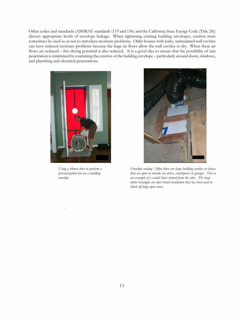
HOT DRY, MIXED-DRY AND MARINE
HVAC SYSTEM ONLY HVAC SYSTEM PLUS ENVELOPE
RETROFIT #1 Ducts sealed (leakage decreased to <10% of air handler flow) Ducts outside conditioned space insulated to R8 (RSI 1.4) Correct refrigerant charge
Ducts sealed (leakage decreased to <10% of air handler flow) Ducts outside conditioned space insulated to R8 (RSI 1.4) Correct refrigerant charge Ducts sealed and buried in added ceiling insulation. New downsized ducts and HVAC equipment. The ducts are installed to minimize the flow resistance, i.e. correct length, good routing and preferably sheet metal construction.
RETROFIT #2 Ducts sealed (leakage decreased to <10% of air handler flow) Ducts outside conditioned space insulated to R8 (RSI 1.4) Correct refrigerant charge Added economizer
Ducts sealed (leakage decreased to <10% of air handler flow) Ducts outside conditioned space insulated to R8 (RSI 1.4) Correct refrigerant charge Ducts sealed and buried in added ceiling insulation. New downsized ducts and HVAC equipment. The ducts are installed to minimize the flow resistance, i.e. correct length, good routing and preferably sheet metal construction. Added economizer
RETROFIT #3 Ducts sealed (leakage decreased to <10% of air handler flow) Ducts outside conditioned space insulated to R8 (RSI 1.4) Correct refrigerant charge Added economizer Higher solar reflectance roof, more window shading.
Ducts sealed (leakage decreased to <10% of air handler flow) Ducts outside conditioned space insulated to R8 (RSI 1.4) Correct refrigerant charge Ducts sealed and buried in added ceiling insulation. New downsized ducts and HVAC equipment. The ducts are installed to minimize the flow resistance, i.e. correct length, good routing and preferably sheet metal construction. Added economizer Higher solar reflectance roof, more window shading.
19

COLD AND SEVERE COLD (AND SUBARCTIC/ARCTIC)
In some severe cold climates summertime humidity levels can be high enough to be uncomfortable for occupants and houses will have air-conditioning. Although the air-conditioning systems in this climate do not use large amounts of energy because they only operate for the hottest few weeks of the year, their design and installation can still be optimized. The air-conditioner should be chosen and operated to maximize humidity control.
This retrofit is suitable for dry summer climates within the colder zones. Air conditioners are removed completely if CDH23 < 1400 (CDH74 < 2500) and mean monthly dewpoint < 15.5°C (60°F). A listing of these data for various locations is given in a Dry Summer Locations table. Cooling is provided by an economizer in these climates.
HVAC SYSTEM ONLY HVAC SYSTEM PLUS ENVELOPE
RETROFIT #1 Ducts moved inside conditioned space or sealed (leakage decreased to <10% of air handler flow) and insulated to R8 (RSI 1.4).
Ducts moved inside conditioned space or sealed (leakage decreased to <10% of air handler flow) and insulated to R8 (RSI 1.4). Upgrade windows. Add ceiling/wall/floor insulation. New downsized ducts and replace HVAC equipment. The ducts are installed to minimize the flow resistance, i.e. correct length, good routing and preferably sheet metal construction
RETROFIT #2 Ducts moved inside conditioned space or sealed (leakage decreased to <6% of air handler flow) and insulated to R8 (RSI 1.4). Replace air-conditioner with downsized unit that has air-handler flow at the lower end of the manufacturers specifications.
Ducts moved inside conditioned space or sealed (leakage decreased to <6% of air handler flow) and insulated to R8 (RSI 1.4). Upgrade windows. Add ceiling/wall/floor insulation. New downsized ducts and replace HVAC equipment. The ducts are installed to minimize the flow resistance, i.e. correct length, good routing and preferably sheet metal construction.
RETROFIT #3a 1Ducts moved inside conditioned space or sealed (leakage decreased to <6% of air handler flow) and insulated to R8 (RSI 1.4). Upgrade windows. Add ceiling/wall/floor insulation. Add an economizer. Remove air-conditioning if present- this includes outdoor unit, refrigerant lines and indoor coil.
RETROFIT #3b 1Ducts moved inside conditioned space or sealed (leakage decreased to <6% of air handler flow) and insulated to R8 (RSI 1.4). Upgrade windows. Add ceiling/wall/floor insulation. Add an economizer. Remove air-conditioning if present- this includes outdoor unit, refrigerant lines and indoor coil.
20

Replace existing furnace with new furnace.
21

MIXED-HUMID AND HOT HUMID
In these climates we do not recommend the use of economizers because outdoor air adds a significant humidity load to the building. To control humidity, use a separate humidity control system, for example, a dehumidifier in an internal air handler closet (http://www.buildingscience.com/housesthatwork/hothumid/wood/default.htm) and low flow air circulation fan. Other recommendations about sealing and insulating duct locations (to effectively bring them inside the conditioned space) are important in humid locations to reduce the problems associated with condensation in cold duct surfaces.
HVAC SYSTEM ONLY HVAC SYSTEM PLUS ENVELOPE
RETROFIT #1 Ducts sealed (leakage decreased to <10% of air handler flow) and insulated to R8 (RSI 1.4) Correct refrigerant charge. Install kitchen and bathroom exhaust fans.
Ducts sealed (leakage decreased to <10% of air handler flow) and insulated to R8 (RSI 1.4). Correct refrigerant charge. Install kitchen and bathroom exhaust fans. Seal and insulate attics and crawlspaces containing ducts.
RETROFIT #2 Ducts sealed (leakage decreased to <10% of air handler flow) and insulated to R8 (RSI 1.4). Correct refrigerant charge. Install kitchen and bathroom exhaust fans. Replace air-conditioner with correctly sized unit.
Ducts sealed (leakage decreased to <10% of air handler flow) and ducts outside conditioned space insulated to R8 (RSI 1.4). Correct refrigerant charge. Install kitchen and bathroom exhaust fans. Seal and insulate attics and crawlspaces containing ducts. New downsized ducts and HVAC equipment. The ducts are installed to minimize the flow resistance, i.e. correct length, good routing and preferably sheet metal construction. Replace air-conditioner with correctly sized unit.
RETROFIT #3 Ducts sealed (leakage decreased to <10% of air handler flow) and insulated to R8 (RSI 1.4). Correct refrigerant charge Replace air-conditioner with correctly sized unit. Install kitchen and bathroom exhaust fans. Upgrade windows. Add ceiling/wall/floor insulation
Ducts sealed (leakage decreased to <10% of air handler flow) and ducts outside conditioned space insulated to R8 (RSI 1.4). Correct refrigerant charge. Seal and insulate attics and crawlspaces containing ducts. New downsized ducts and HVAC equipment. The ducts are installed to minimize the flow resistance, i.e. correct length, good routing and preferably sheet metal construction. Replace air-conditioner with correctly sized unit. Install kitchen and bathroom exhaust ans. Upgrade windows. Add ceiling/wall/floor insulation.
22

POTENTIAL RETROFITS
The following retrofits have been selected because they are all off the shelf existing technologies, and cover a range of energy, comfort and durability issues:
• Seal the ducts to less than 10% of air handler flow. Ducts can be sealed using a variety of techniques and materials including tapes mastics and aerosols. Standard cloth tapes should never be used to seal ducts due to their poor durability.
• Add duct insulation to ducts. Ducts outside conditioned space should have R8 (RSI 1.4) insulation.
Before After
23

Blown –in insulation with cardboard forms Installing Duct Wrap
• Seal and insulate duct locations – attics or crawlspaces. This brings the ducts inside the conditioned space- thus minimizing their losses. In humid climates there is the additional benefit of reducing the chances of condensation on cold ducts in contact with outdoor air. However there are some caveats regarding sealing attics in warm humid climates as care must be taken to avoid moisture penetration of the roofing materials that can lead to buckling and failure of shingles. A good method of avoiding these problems is to use an impermeable underlay beneath the shingles. More details are available at http://www.buildingscience.com/resources/roofs/unvented_roof.pdf and http://www.buildingscience.com/resources/roofs/Unvented_Attic_Discussion.pdf. Crawlspace sealing must include ground cover to reduce moisture and radon entry into the crawlspace.
Illustration of an unvented attic. The insulation has been moved from the attic floor to the pitched roof
surfaces and all the attic vents have been sealed. Because the attic is now inside conditioned space – the ducts losses are very small.
• Increase indoor evaporator coil size in dry air conditioning climates. The increase in coil size will
increase efficiency and change the latent/sensible capacity in favor of sensible capacity. • Correct air handler flow. Increasing air handler flow will increase heat exchanger and coil efficiency
and change the latent/sensible capacity in favor of sensible capacity. It also has the potential to increase
24

mixing of air between rooms of the house and within individual rooms. This extra mixing can have comfort benefits and potential energy saving benefits if it allows the occupants to change thermostat settings to reduce energy use. For humid climates the increased efficiency needs to be balanced against the reduction in latent capacity, however a well sealed building envelope with controlled ventilation will significantly reduce the latent load due to infiltration, allowing the use of higher air flow rates. Separate dehumidification systems in humid climates also allow the air handler flow to be set high and optimized for efficient sensible cooling. For heat pumps, air flow rates need to balance the increase in efficiency against the lower air delivery temperatures when heating that can lead to poor thermal comfort. For furnaces, air flows that are too low can lead to overheating and short cycling on the high limit switch. Even before these extremes, hotter air inside the ducts at low air flows leads to increased conduction losses from ducts outside conditioned space.
• Downsize replacement systems. The extra cost of non-HVAC equipment related retrofits can be compensated for by the reduced cost of a lower capacity heating and cooling system. This strategy is being used successfully in new construction (for example by Building America). Downsizing should also include the reduction of duct diameter with lower air flows in order maintain throw from registers for good room mixing.
• Move registers. Instead of having long duct runs out to the exterior walls, improved windows and envelope insulation allow the registers to be placed closer to the center of the building. This results in much shorter duct runs that reduce duct losses and reduces material and labor costs.
• Add an economizer. In dry cooling climates an economizer can significantly reduce compressor operation and result in energy savings at the same time as providing ventilation air. If the economizer is connected to the forced air system (as is usually done) it will help to ensure good thermal and fresh air mixing throughout the house. Sealed and well-insulated ducts are a requirement for using an economizer. Because the optimum air flow for economizers is often less than the standard air handler flow it is important to have an air handler that operates efficiently at lower speeds – usually this means specifying a BPM (Brushless Permanent Magnet). Economizer operation needs to be carefully checked to make sure that the flow control dampers are operating properly – including pressure relief dampers. The outdoor air should be filtered before it enters the house. This can most easily be accomplished by introducing the outdoor air into the forced air system before the filters. This means that filters will not be placed at return grilles and will probably be placed at the air handler filter slot or in the economizer air flow control system itself. The filters are then in a location not easily observed by the homeowner, so some effort is required to make the homeowner aware of this so that they will still make regular filter changes.
• Add ventilation. Several potential methods exist: kitchen/bath exhaust, single supply into central system (with continuous central air handler operation), single supply into central system that operates periodically (for example BSC’s AirCycler system used in their Building America houses (http://www.buildingscience.com/resources/mechanical/default.htm)). Ventilation air may require filtration, or be conditioned by an extra smaller cooling system. The ventilation system needs to be integrated with the economizer operation (they may even be the same physical components, just with a different control strategy depending on system operating characteristics). For example, economizer air flow is typically much higher than ventilation air flow. Adding ventilation is particularly important if the building envelope has been significantly tightened by sealing leaks or adding insulation. Various ventilation standards give guidance on mechanical ventilation requirements. A good rule of thumb is to provide 7.5 cfm (3.5 L/s) per person (where the number of persons is determined by the higher of the number of bedrooms +1 or the known number of occupants) combined with local pollutant exhausts in kitchens and bathrooms. For intermittent operation kitchen fans should be sized at a minimum of 100cfm and bathroom fans at 50 cfm (25 L/s). Kitchen fans should always be vented to outside and not recirculate. Many houses have existing kitchen and bathroom fans that usually operate poorly – creating lots of noise but not moving much air. Replacement fans should be chosen to be energy efficient and
25
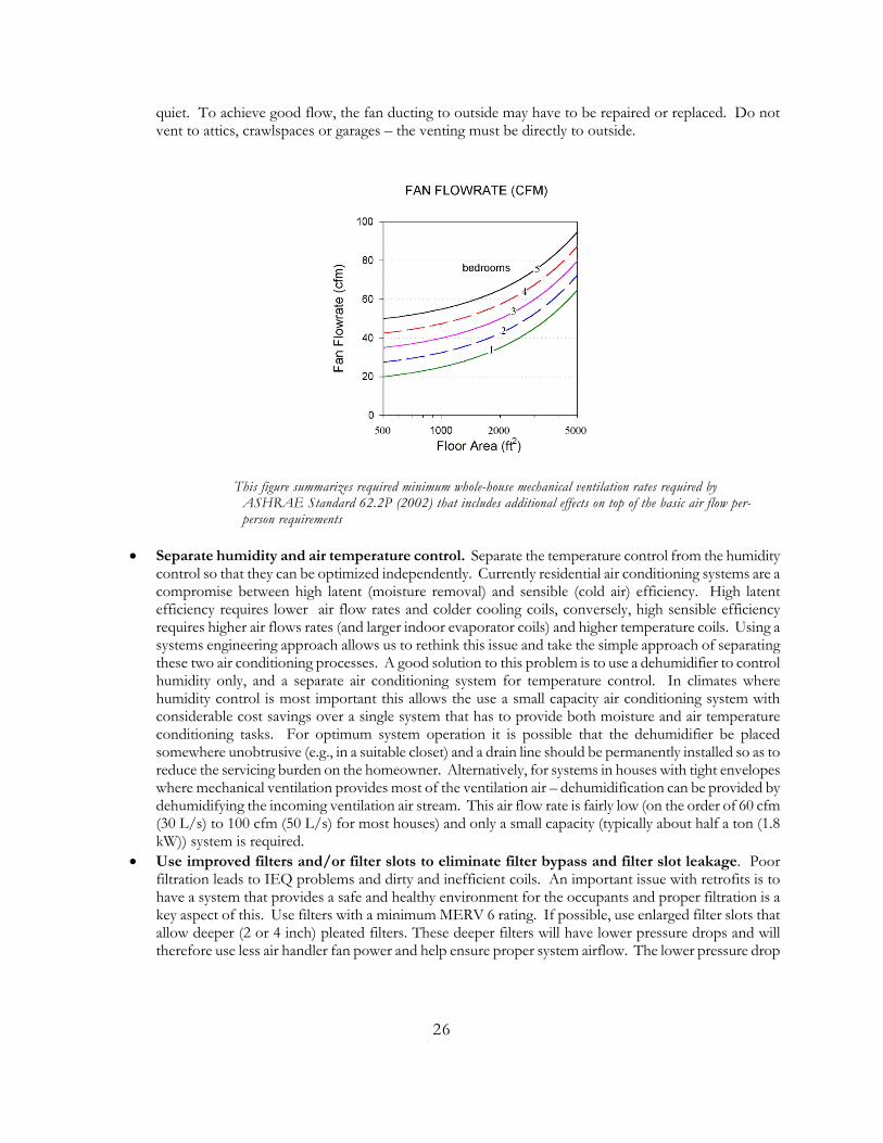
quiet. To achieve good flow, the fan ducting to outside may have to be repaired or replaced. Do not vent to attics, crawlspaces or garages – the venting must be directly to outside.
This figure summarizes required minimum whole-house mechanical ventilation rates required by ASHRAE Standard 62.2P (2002) that includes additional effects on top of the basic air flow per-person requirements
• Separate humidity and air temperature control. Separate the temperature control from the humidity control so that they can be optimized independently. Currently residential air conditioning systems are a compromise between high latent (moisture removal) and sensible (cold air) efficiency. High latent efficiency requires lower air flow rates and colder cooling coils, conversely, high sensible efficiency requires higher air flows rates (and larger indoor evaporator coils) and higher temperature coils. Using a systems engineering approach allows us to rethink this issue and take the simple approach of separating these two air conditioning processes. A good solution to this problem is to use a dehumidifier to control humidity only, and a separate air conditioning system for temperature control. In climates where humidity control is most important this allows the use a small capacity air conditioning system with considerable cost savings over a single system that has to provide both moisture and air temperature conditioning tasks. For optimum system operation it is possible that the dehumidifier be placed somewhere unobtrusive (e.g., in a suitable closet) and a drain line should be permanently installed so as to reduce the servicing burden on the homeowner. Alternatively, for systems in houses with tight envelopes where mechanical ventilation provides most of the ventilation air – dehumidification can be provided by dehumidifying the incoming ventilation air stream. This air flow rate is fairly low (on the order of 60 cfm (30 L/s) to 100 cfm (50 L/s) for most houses) and only a small capacity (typically about half a ton (1.8 kW)) system is required.
• Use improved filters and/or filter slots to eliminate filter bypass and filter slot leakage. Poor filtration leads to IEQ problems and dirty and inefficient coils. An important issue with retrofits is to have a system that provides a safe and healthy environment for the occupants and proper filtration is a key aspect of this. Use filters with a minimum MERV 6 rating. If possible, use enlarged filter slots that allow deeper (2 or 4 inch) pleated filters. These deeper filters will have lower pressure drops and will therefore use less air handler fan power and help ensure proper system airflow. The lower pressure drop
26

also means that the return ducts downstream of the filter operate under a lower negative pressure, thus reducing duct leakage effects.
These illustrations show dirty and clean pleated filters, a very dirty coil that had been exposed to unfiltered air and a poorly installed filter that leads to filter bypass and most of the air flowing through this system would be unfiltered.
• Add solar shading to existing windows in predominantly cooling climates. • Use solar reflective house paint on roof (and possibly walls) of the house in predominantly cooling
climates (see notes on solar gain reduction). • Improve envelope thermal performance. Air sealing of the building envelope is a good way to reduce
the energy used to condition the house. It also allows better control of the indoor conditions by using controlled mechanical ventilation, it increases the effectiveness of economizers and allows significantly better indoor humidity control. Target large openings first, such as chases that are open to attics or crawlspaces. Adding insulation to all parts of a building envelope is only really practical as part of a complete building renovation or repair. However adding insulation to attic spaces to reduce ceiling heat transfer can be effective – in particular – if ducts on attic floors can be buried in a thick layer of additional insulation due to the additional benefits from reduced duct losses. In situations where it is difficult to obtain code approval for sealing attic spaces completely, this covering of the ducts in added insulation is a reasonable second best option. However, ducts should not be buried in humid climates due to the potential for condensation on the cold duct surfaces.
• Use indirect evaporative cooling instead of a refrigerant based system. For example, the Davis Energy Group “nightbreeze” system (http://www.davisenergy.com/nb_page.htm) uses indirect evaporative cooling to provide cooled water to cooling coils for a forced air conditioning system.
• Add ceiling fans to more evenly distribute cooling in rooms/spaces that are supplied by smaller air flows from downsized systems. It is best to select energy efficient ceiling fans such as the fan developed at FSEC: http://www.fsec.ucf.edu/bldg/active/bdac/prototype/cfan.htm
• Use register grilles that have reduced pressure drops and noise, and better throw into the room for better mixing. Grilles should be chosen and located such that the high velocity air does not enter the occupied parts of the room directly. Noise and pressure-drop reduction is aided by selecting grilles with curved blades and by placing air flow control dampers at plenum take-offs (this also reduces duct system pressures and therefore has the potential to reduce leakage).
• Replace windows with improved double pane units. Because of the expense – this retrofit would probably only be performed in conjunction with HVAC retrofits for separate reasons, e.g., condensation problems with existing windows or problems with existing windows so that they would have to be replaced anyway. Depending on climate, low emittance coatings are available at little increased cost and can contribute to better control of solar loads (either increasing solar gains in heating climates or reducing them in cooling climates).
27

Return to retrofit selection
EPA ENERGY STAR DUCTS
The EPA has developed a simplified program for retrofitting HVAC systems that specifies:
Less than 10% duct leakage or 85% ASHRAE 152P Efficiency
Minimum duct insulation level of R6 (RSI 1)
Correct air handler fan flow
http://estar4.energystar.gov/estar/ducts.nsf/webpages/contractors.html
http://estar4.energystar.gov/estar/ducts.nsf/webpages/homeowners.html
Return to retrofit selection
OTHER PUBLISHED GUIDELINES
Other good resources for advice on energy efficient durable housing that can be applied to retrofits are: No regrets Remodeling, published by Home Energy magazine, Berkeley, CA. (www.homeenergy.org) The Builders guides published by Energy and Environmental Builders Association (EEBA – who can be found online at: http://www.eeba.org/). These guides give thorough building detail illustrations. HUD renovation guides by Lstiburek and Brennan. Previous LBNL studies for the California Energy Commission: LBNL 45959 (Metrics and Diagnostics for Commissioning) A wide range of inline information is also provided by NAHB/HUD/PATH through their ToolBase Services at: http://www.toolbase.org/index-toolbase.asp Specifically examples on duct remodeling: http://www.toolbase.org/tertiaryT.asp?TrackID=&CategoryID=1534&DocumentID=2302
28

TRAINING
Excellent training that covers the retrofit issues raised here is provided by organizations such as EEBA and Affordable Comfort. The following website, hosted by homenergy magazine has a comprehensive list of trainers throughout the US: http://homeenergy.org/hewebsite/contraininguide/index.html.
WHY RETROFITS ARE DIFFERENT FROM NEW CONSTRUCTION
Access. One access issue is the physical location of the components (for example ducts) to be retrofitted that would be exposed and easy to work on in new construction. This often limits the range of retrofit activities or the applicability of certain retrofits. For example duct sealing, insulation or replacement can be difficult, in not impossible, for ducts hidden in wall and floor cavities. In new construction the tradeoffs for improved HVAC equipment and building envelopes are often much easier. For example, in a new home the cost of installing good windows is just the difference between the good windows and poor windows rather than the total cost of the windows plus installation. Home owner NOT builder. Home owners are generally not familiar with building or HVAC system functions and operation. They have considerably less access to financing, and are more averse to risk – mostly because they have to live directly with the consequences of any change to the building. This means that a contractor needs to educate the homeowner in a convincing way in order to successfully carry out the retrofit work. In other cases, homeowners may have very specific requirements based on a wide variety of knowledge – some of which may be incorrect. Lastly – because individual houses are so different and occupant lifestyles can vary widely, retrofits tend to be done on a house-by-house basis – with the associated high overhead. For builders many similar (if not identical houses) will be worked on by a contractor so that overhead costs can be spread over many installations and equipment and materials can be purchased in greater quantities with resulting lower prices. One of the objectives of this guide is to allow contractors to develop specific solutions to retrofits that can be used repeatedly so as to amortize overhead costs over more installations and so that a contractor can develop packages of retrofits using similar equipment and the equipment and materials can therefore be purchased in greater quantities at resulting lower costs. Financing. Although there are energy efficient mortgages available to amortize the expense of retrofits, many retrofits are paid directly with cash by homeowners. Return to introduction.
KEEPING IT SIMPLE
When it comes to most peoples biggest investment – their home - nobody wants to be a guinea-pig. That is why the focus of these guidelines is on existing technologies and construction/installation methods. The innovation here is that we attempt to look at how the individual components of a building combined – i.e. a systems engineering approach. No new practices or equipment need to be imposed on builders/contractors, instead we
29

plan to change how systems are designed and installed. All the material aspects of the best practices are readily available. Lastly, we avoid expensive solutions to lowering energy bills because we want solutions that can be used by normal homeowners. In many cases we are able to trade off changes between various house and HVAC system components. The greatest example of this is the reduction in cost of downsized heating and cooling equipment (and associated duct systems) balances the cost of building envelope improvements (added insulation or better replacement windows). This results in a system that uses considerably less energy, results in a more comfortable home and does not always cost more money. In addition to the cost savings associated with correctly sized equipment, there can also be future returns on the investment because it adds value to a home. In particular, if the screening checklist shows that additional retrofits that were not part of the homeowners original plan are a good idea, then the increased value of the home may be a good selling point. Successful examples of these tradeoffs for new construction are illustrated in Building Science case studies: http://www.buildingscience.com/buildingamerica/casestudies/default.htm. Another aspect of the keeping it simple idea is to carefully examine the existing HVAC system to see what can be salvaged, saved or reused. Parts of the system that are functioning well should be retained as much as possible. A good example is sheet metal ducts that are normally replaced with new flexible duct by contractors. The sheet metal ducts have much less flow resistance (and therefore less noise) and superior durability. If they can be sealed (if leaky) and insulated (if uninsulated), they should be retained if possible. Return to introduction.
DURABILITY
Retrofits need to be durable so that the benefits will still be in place 25 to 50 years from now. Examples of durability concerns include not using cloth duct tape (due to thermal degradation) and avoiding moisture problems. This last issue is an illustration of the building-as-a-system approach where it is necessary to examine how each building component interacts with other components. For example, tightly sealing the walls and ceiling of a house while allowing moist air from a damp crawlspace to enter through the floor will invariably lead to moisture problems due to condensation on cold surfaces (usually most noticeable on windows). These moisture problems will eventually lead to issues such as structural failure and poor indoor air quality, thus affecting the durability of he building envelope itself and also durability in the sense that the building provides safe and comfortable living environment for the occupants. A mold infested home that cannot be occupied is not “durable”. Note that even in “dry” climates, exterior water penetration of the envelope or damp soil can lead to moisture problems. Return to introduction.
30

INPUT FROM INDUSTRY
These best practice guidelines were developed by combining research knowledge with good ideas from the building industry. Forums were conducted at meetings of the following organizations in order to discuss issues facing the retrofit industry and the guidance that is needed to improve current retrofit practice:
• Energy and Environmental Builders Association (http://www.eeba.org/)
• Affordable Comfort (http://www.affordablecomfort.org/home1.html)
• Building America Teams (http://www.eren.doe.gov/buildings/building_america/)
The author would like to thank the following people contributed to this guide: Jennifer McWilliams (LBNL), Steve Konopacki (LBNL), Evan Mills (LBNL), Diane Griffiths (Steven Winter Associates), Kohta Ueno (Building Science Corp.), Rob Hammon (Consol), Terry Logee (DOE), Glenn Hourahan (ACCA), Bob Knight (BKI), Rick Chitwood (Chitwood Energy Management). Return to introduction.
REFERENCES
ASHRAE. 2004. ASHRAE Standard 152 – Method of Test for Determining Design and Seasonal Efficiency of Residential Thermal Distribution Systems. American Society of Heating Refrigeration and Air-Conditioning Engineers, Atlanta, GA. ASTM. 2003. ASTM E1554-03 - Standard Test Method for Determining External Air Leakage of Air Distribution Systems by Fan Pressurization. American Society of Testing and Materials, West Conshohocken, PA. ASTM. 2003. ASTM E779-03 – Standard Test Method for Determining Air Leakage Rate by Fan Pressurization. American Society of Testing and Materials, West Conshohocken, PA. EIMA. 2000. “EIMA Guidelines & Checklist”. Morrow, GA: EIFS Industry Members Association. http://www.dryvit.com/eima.htm. November 1. GAHI. 2000. “The GAHI Protocol for Exterior Insulation Finishing Systems (EIFS) Moisture Intrusion Inspections – One & Two Family Homes”. Atlanta, GA: Georgia Association of Home Inspectors. http://www.gahi.com/eifsprot.html. November 1.
31

NHCID. 1998. “Moisture Testing Guide for Wood Frame Construction Clad with Exterior Insulation and Finish Systems (EIFS), Version 3.01”. Prepared for EIFS Review Committee. Wilmington, NC: New Hanover County Inspection Department. August 4.
32

33
DRY SUMMER LOCATIONS THAT CAN USE AN ECONOMIZER
This table uses data from ASHRAE 90.2 (that references the Climate Atlas of the United States, National Climate Data Center, Asheville, NC.) that gives mean monthly dewpoint temperatures. It assumes that locations with > 2500 CDH74 (>1400 CDH23) will require A/C and an economizer alone will not be sufficient. {PRIVATE }STATE LOCATION ALASKA ALL ARIZONA Flagstaff CALIFORNIA EUREKA
MT. SHASTA OAKLAND SAN FRANCISCO SANTA MARIA
MAINE CARIBOU EASTPOINT PORTLAND
MASSACHUSETS WORCESTER MICHIGAN ALPENA
ESCANABA MARQUETTE SAULT STE. MARIE
DULUTH INTERNATIONAL FALLS
MONTANA BUTTE KALISPELL MISSOULA
NEVADA ELY RENO
NEW HAMPSHIRE CONCORD MT. WASHINGTON
NEW YORK BINGHAMTON CANTON OSWEGO
OREGON ASTORIA BAKER BURNS EUGENE PORTLAND ROSEBURG SALEM
PENNSYLVANIA ERIE VERMONT BURLINGTON WASHINGTON OLYMPIA
SEATTLE AP SEATTLE –TACOMA STAMPEDE PASS TACOMA
WISCONSIN GREEN BAY WYOMING CHEYENNE
ROCK SPRINGS Return to retrofit list