best practices for hp 10000 series and hp 10000 g2 series racks
TRANSCRIPT
Best practices for HP 10000 Series and HP 10000 G2 Series Racks best practice
Abstract.............................................................................................................................................. 1
10000 G2 Series overview .................................................................................................................. 1
Product availability .............................................................................................................................. 3
Specifications...................................................................................................................................... 3 Dimensions...................................................................................................................................... 4 Additional Resources ........................................................................................................................ 6
Certification and regulatory compliance ................................................................................................. 6 Product certification.......................................................................................................................... 6 HP General Specification for Environment compliance.......................................................................... 6 Information Technology Equipment..................................................................................................... 6
Waste Electrical and Electronic Equipment directive ......................................................................... 6
Integration services and software........................................................................................................... 7 HP Factory Express........................................................................................................................... 7
Additional resources ..................................................................................................................... 7 HP eCo-Enterprise Configurator ......................................................................................................... 7
Additional resources ..................................................................................................................... 7 HP UPS Sizing Tool .......................................................................................................................... 7
Additional resources ..................................................................................................................... 7 Rack documentation CD.................................................................................................................... 8
Rack deployment considerations............................................................................................................ 8 Levels of rack security ....................................................................................................................... 8
HP 10000 G2 Series rack front doors ............................................................................................ 8 HP 10000 G2 Series rack rear doors ............................................................................................. 8 HP Side Panel Option Kit............................................................................................................... 8
Stabilization requirements ................................................................................................................. 8 Leveling feet................................................................................................................................. 8 HP 10000 Baying Kit ................................................................................................................... 9 HP 10000 Stabilizer Kit ................................................................................................................ 9 HP 10000 Ballast Option Kit ....................................................................................................... 10
Stabilization for seismic activity ....................................................................................................... 10 HP 10000 Series Plinth Option Kit ............................................................................................... 11
HP 10000 G2 Series Tie Down Option Kit .................................................................................... 11 Space and cable management requirements ..................................................................................... 11
Extension kits ............................................................................................................................. 11 Cable management kits............................................................................................................... 12
Thermal requirements ..................................................................................................................... 12 Additional resources....................................................................................................................... 13
Rack assembly guidelines ................................................................................................................... 13 Additional resources....................................................................................................................... 13
Installation and maintenance precautions ............................................................................................. 14 Moving racks with casters ........................................................................................................... 14 Connecting and disconnecting power to hot-pluggable power supplies............................................. 14 Rack-mountable products............................................................................................................. 15
Data Center planning and considerations ............................................................................................. 16 Environmental considerations .......................................................................................................... 16
Thermal considerations ............................................................................................................... 16 Third-party thermal considerations.................................................................................................... 18 Power considerations...................................................................................................................... 19
Power redundancy ..................................................................................................................... 19 Non-redundant........................................................................................................................... 19 High line voltage versus low line voltage....................................................................................... 19 Grounding and Earth leakage current ........................................................................................... 20 Additional resources ................................................................................................................... 20
Equipment clearance and floor loading ................................................................................................ 20 Rack and accessory footprints.......................................................................................................... 21
Front door clearance .................................................................................................................. 22
Qualified shipping............................................................................................................................. 23 Qualification of rack components for shipping................................................................................... 24 Rack shipping enclosures ................................................................................................................ 24
Standard shipping pallet ............................................................................................................. 24 CTO shock pallet........................................................................................................................ 24 Horizontal crate ......................................................................................................................... 25 Vertical crate for rack options ...................................................................................................... 25 Shipping specifications ............................................................................................................... 26
10000 and 10000 G2 Series Rack packing materials ....................................................................... 27 Preparation for shipment ................................................................................................................. 27 Site preparation for receiving Integrated Racks .................................................................................. 28 General considerations (all shipments).............................................................................................. 28 Special shipping considerations....................................................................................................... 29 Door Height Clearances ................................................................................................................. 30 Modes of shipment......................................................................................................................... 30 Airfreight ...................................................................................................................................... 31
International Air Transport Association labeling ............................................................................. 31 Mode of receiving and delivery ....................................................................................................... 33 10000 and 10000 G2 Series Rack packing and shock pallet assembly............................................... 34 Dismounting a 10000 G2 Series Rack from a shock pallet.................................................................. 42
Installation service.............................................................................................................................. 43 Spares kits .................................................................................................................................... 43 Additional tools and equipment ....................................................................................................... 43 Battery decals and boxes ................................................................................................................ 43
Appendix a: glossary......................................................................................................................... 44
Appendix b: torque values.................................................................................................................. 45
1
Abstract This document outlines recommended practices for configuring, installing, transporting, and establishing a work environment for the HP 10000 and HP 10000 Generation 2 (G2) Series Racks, which includes the following models:
• 10000 Series rack models – S10614
• 10000 G2 Series rack models – 10622 G2 – 10636 G2 – 10642 G2 – 10647 G2 – 10842 G2
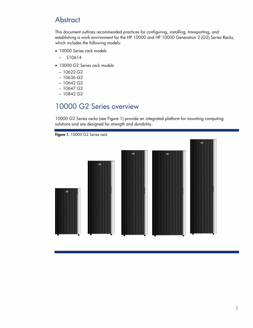
10000 G2 Series overview 10000 G2 Series racks (see Figure 1) provide an integrated platform for mounting computing solutions and are designed for strength and durability.
Figure 1. 10000 G2 Series rack
2
HP racks and rack accessories ease the centralization, protection, organization, and access to hardware for servicing and upgrading. HP racks are flexible, secure, and designed to industry standards. HP racks are designed be populated with the following HP products:
• HP ProLiant servers • HP BladeSystem servers • HP 9000 servers • HP Integrity servers • HP StorageWorks products • HP rack mount power protection products • HP rack mount switches • HP rack mount monitors
The 10000 G2 Series racks are designed for greater ease-of-use. The 10000 G2 Series rack design is based on the original 10000 Series racks.
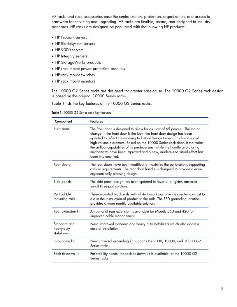
Table 1 lists the key features of the 10000 G2 Series racks.
Table 1. 10000 G2 Series rack key features
Component Features
Front door The front door is designed to allow for air flow of 65 percent. The major change in the front door is the look; the front door design has been updated to reflect the evolving Industrial Design tastes of high value and high volume customers. Based on the 10000 Series rack door, it maintains the airflow capabilities of its predecessors, while the handle and closing mechanisms have been improved and a new, modernized visual effect has been implemented.
Rear doors The rear doors have been modified to maximize the perforations supporting airflow requirements. The rear door handle is designed to provide a more ergonomically pleasing design.
Side panels The side panel design has been updated in favor of a lighter, easier to install three-part solution.
Vertical ElA mounting rails
These e-coated black rails with white U-markings provide greater contrast to aid in the installation of product to the rails. The ESD grounding location provides a more readily available solution.
Rear extension kit An optional rear extension is available for Models 36U and 42U for improved cable management,
Standard and heavy-duty stabilizers
New, improved standard and heavy duty stabilizers which also address ease of installation.
Grounding kit New universal grounding kit supports the 9000, 10000, and 10000 G2 Series racks.
Rack tie-down kit For stability needs, the rack tie-down kit is available for the 10000 G2 Series racks.
3
Product availability The 10000 Series rack Model S10614 is available.
NOTE The following 10000 Series rack models are discontinued:
• 10622
• 10636
• 10642
• 10647 • 10842
Specifications The 10000 and 10000 G2 Series racks are graphite-metallic in color and are available in the rack heights listed in Table 2. The racks are one-meter deep allowing more room for cable management and for accommodating deeper server and storage equipment.
Additional cable management features are as follows:
• Wide (or 800-mm) rack models can accommodate network cabling on the sides of the rack. • A cable egress in the top of the rack allows for overhead data center cabling. • Split rear doors provide greater efficiency with respect to service access. • A removable access panel on the rear door provides added flexibility for cable routing out the rear
and bottom of the rack. • Velcro straps for bundling cables within the rack are included in the hardware kit and also
available as an option.
4
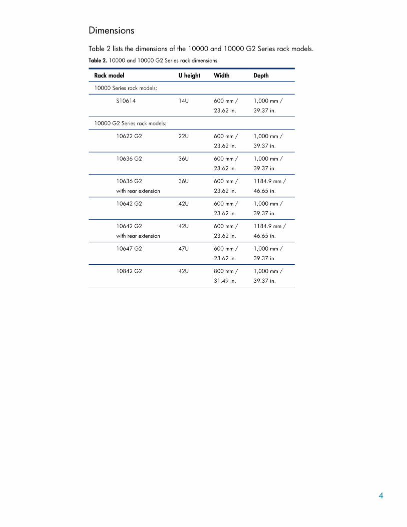
Dimensions
Table 2 lists the dimensions of the 10000 and 10000 G2 Series rack models.
Table 2. 10000 and 10000 G2 Series rack dimensions
Rack model U height Width Depth
10000 Series rack models:
S10614 14U 600 mm /
23.62 in.
1,000 mm /
39.37 in.
10000 G2 Series rack models:
10622 G2 22U 600 mm /
23.62 in.
1,000 mm /
39.37 in.
10636 G2 36U 600 mm /
23.62 in.
1,000 mm /
39.37 in.
10636 G2
with rear extension
36U 600 mm /
23.62 in.
1184.9 mm /
46.65 in.
10642 G2 42U 600 mm /
23.62 in.
1,000 mm /
39.37 in.
10642 G2
with rear extension
42U 600 mm /
23.62 in.
1184.9 mm /
46.65 in.
10647 G2 47U 600 mm /
23.62 in.
1,000 mm /
39.37 in.
10842 G2 42U 800 mm /
31.49 in.
1,000 mm /
39.37 in.
5
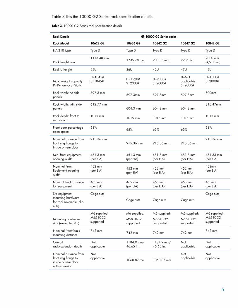
Table 3 lists the 10000 G2 Series rack specification details.
Table 3. 10000 G2 Series rack specification details
Rack Details HP 10000 G2 Series racks
Rack Model 10622 G2 10636 G2 10642 G2 10647 G2 10842 G2
EIA-310 type Type D Type D Type D Type D Type D
Rack height max. 1113.48 mm 1735.78 mm 2003.5 mm 2285 mm 2000 mm
(+/- 3 mm)
Rack U height 22U 36U 42U 47U 42U
Max. weight capacity D=Dynamic/S=Static
D=1045# S=1045#
D=1520# S=2000#
D=2000# S=2000#
D=Not applicable S=2000#
D=1000# S=2000#
Rack width: no side panels
597.3 mm 597.3mm 597.3mm 597.3mm 800mm
Rack width: with side panels
612.77 mm 604.3 mm 604.3 mm 604.3 mm
815.47mm
Rack depth: front to rear door
1015 mm 1015 mm 1015 mm 1015 mm 1015 mm
Front door percentage open space
63% 65% 65% 65% 63%
Nominal distance from front mtg flange to inside of rear door
915.36 mm 915.36 mm 915.36 mm 915.36 mm
915.36 mm
Min. front equipment opening width
451.3 mm (per EIA)
451.3 mm (per EIA)
451.3 mm (per EIA)
451.3 mm (per EIA)
451.33 mm (per EIA)
Nominal Front Equipment opening width
452 mm (per EIA)
452 mm (per EIA)
452 mm (per EIA)
452 mm (per EIA)
452mm (per EIA)
Nom Ctr-to-ctr distance for equipment
465 mm (per EIA)
465 mm (per EIA)
465 mm (per EIA)
465 mm (per EIA)
465mm (per EIA)
Std equipment mounting hardware for rack (example, clip nuts)
Cage nuts
Cage nuts Cage nuts Cage nuts
Cage nuts
Mounting hardware size (example, M5)
M6 supplied; M5&10-32 supported
M6 supplied;
M5&10-32 supported
M6 supplied;
M5&10-32 supported
M6 supplied;
M5&10-32 supported
M6 supplied; M5&10-32 supported
Nominal front/back mounting distance
742 mm 742 mm 742 mm 742 mm 742 mm
Overall rack/extension depth
Not applicable
1184.9 mm/ 46.65 in.
1184.9 mm/ 46.65 in.
Not applicable
Not applicable
Nominal distance from front mtg flange to inside of rear door with extension
Not applicable 1060.87 mm 1060.87 mm
Not applicable
Not applicable
6
Additional Resources Additional resources are available as follows:
• For a complete list of HP rack options and accessories, go to the main rack page at www.hp.com/products/racks or to the main rack options page at www.hp.com/products/rackoptions.
• For a list of ProLiant servers and options, go to www.hp.com/products/proliant. • For a list of HP power products such as UPS and PDU, go to www.hp.com/products/ups. • For a complete list of HP server storage equipment, go to www.hp.com/products/serverstorage.
Certification and regulatory compliance
Product certification The10000 and 10000 G2 Series racks are defined as non-functional mechanical storage bays and therefore, are not certified individually as a stand-alone product. The rack does not serve as an overall safety or EMI rated enclosure nor does it carry any other Agency compliant rating. However, any product intended for use in an HP rack should be individually certified as a stand-alone product. For example, HP Power Distribution products, such as uninterruptible power supplies (UPSs) and power distribution units (PDUs) are fully certified as stand-alone products.
Certain third-party products may not be fully certified as stand-alone products. Any product that does not meet stand-alone certification is not included in any HP-specified rack configuration and should not be installed in an HP rack.
HP General Specification for Environment compliance HP General Specification for Environment (GSE) specifications prohibit or restrict the use of certain chemical compounds in products or in the manufacture of products. HP complies with the GSE specifications and restricts the use of these compounds in the development or manufacture of any HP product (including third-party supplier product).
Information Technology Equipment The 10000 and 10000 G2 Series racks are designed to comply with the applicable safety requirements for Information Technology Equipment (ITE) when the rack is configured with properly certified equipment. The 10000 and 10000 G2 Series racks are considered ITE compliant when the following conditions are met:
• The rack is populated with individually certified products • All installation guidelines and instructions are followed
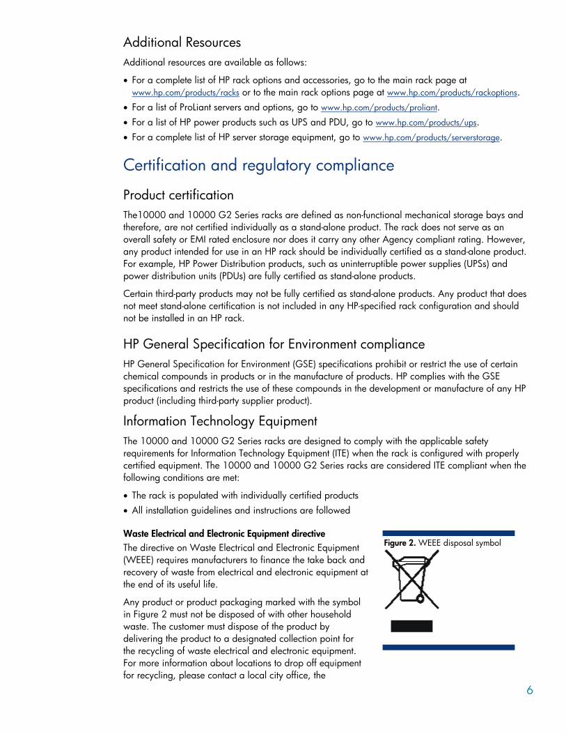
Waste Electrical and Electronic Equipment directive The directive on Waste Electrical and Electronic Equipment (WEEE) requires manufacturers to finance the take back and recovery of waste from electrical and electronic equipment at the end of its useful life.
Any product or product packaging marked with the symbol in Figure 2 must not be disposed of with other household waste. The customer must dispose of the product by delivering the product to a designated collection point for the recycling of waste electrical and electronic equipment. For more information about locations to drop off equipment for recycling, please contact a local city office, the
Figure 2. WEEE disposal symbol
7
household waste disposal service, or the business where the product was purchased.
Integration services and software Several resources are available for planning rack configurations.
HP Factory Express Factory Express is a robust portfolio of flexible, pre-priced, configured, customized and integrated factory solutions and deployment services – supporting HP products from the desktop to the data center with Windows®, Linux, and HP-UX 11i.
Additional resources For specific information, please see the HP Factory Express link: www.hp.com/go/factory-express.
In addition to this available integration option, HP also provides information links and contacts for problem solving of rack and product compatibility in support of Build to Order on site locations through several venues. Please refer to the following resources:
• Frequently Asked Questions about Rack and Power products and interoperability http://iss.tsgonline.hp.com/iss/workgroup/rackandpower/download/Rack 20System 20faqs.doc
• Contact your sales representative for the Interoperability guide to fit and HP ProLiant servers into HP Rack System/E and 9000/10000 racks: http://iss.tsgonline.hp.com/iss/workgroup/rackandpower/interoperability.asp
• To specifically request help on rack and power solutions: http://iss.tsgonline.hp.com/iss/workgroup/rackandpower/requestform.asp
HP eCo-Enterprise Configurator If you require factory default racking for our HP hardware portfolio, you may still use the HP eCo-Enterprise Configurator. If you require "custom" rack configuration capabilities, please contact the HP Customer Business Center or an HP Authorized Partner for assistance.
Additional resources For more information on the eCO Custom Builder tool, refer to the following HP websites:
• eCO-Enterprise Configurator: http://h30099.www3.hp.com/configurator/ • eCO-Enterprise Configurator features: http://h30099.www3.hp.com/configurator/features.asp • Frequently asked questions: http://h30099.www3.hp.com/configurator/docs/eCo_FAQ.doc • What's new: http://h30099.www3.hp.com/configurator/about.asp • Technical support: http://h30099.www3.hp.com/configurator/support.asp
HP UPS Sizing Tool The UPS Sizing tool is an online tool that collects information on power consumption requirements and then provides the correct UPS product for those requirements.
Additional resources For additional information on the UPS Sizing tool, refer to http://www.upssizer.com/selector.asp.
8
Rack documentation CD The Documentation CD shipped with the rack provides documentation for installing and optimizing the rack.
Rack deployment considerations The following sections describe the components and HP options available for the 10000 and 10000 G2 Series racks that may be necessary to achieve safety, regulatory compliance, or functionality requirements.
Levels of rack security Either of the following conditions may be necessary for compliance with certain safety certifications: • Racks must be located in a restricted access area that is only accessible to trained personnel.
-Or- • Racks must be configured with lockable hardware.
HP rack front doors, rear doors, and side panels support this locking requirement. Rear split doors are standard on 10000 and 10000 G2 Series racks. (The 10000 Series rack Model S10614 is not configured with split rear doors).
HP 10000 G2 Series rack front doors All 10000 and 10000 G2 Series rack Models ship with front doors. The 42U and 36U front doors (and necessary hardware) are available as option kits are backwards compatible with the 10000 Series racks of the same heights; this enables customers to have all racks standardized with the same updated look, if desired.
NOTE The front door option kit is not compatible with the 9000 Series racks.
HP 10000 G2 Series rack rear doors All 10000 and 10000 G2 Series rack models ship with rear doors as part of the standard configuration. The 10000 G2 rear door has been upgraded to provide a more ergonomically and cosmetically pleasing handle.
HP Side Panel Option Kit Side panels aid in providing proper front to rear airflow and a first level of security. 10000 Series rack Models S10614 and 10622 ship with side panels installed. Side Panel Option kits are available for all other rack models.
Stabilization requirements Rack stability is of special concern when equipment is routinely installed, removed, or accessed within the rack. Stability is addressed through the use of leveling feet, baying kits, fixed stabilizers, and/or ballast.
Leveling feet Leveling feet are adjustable stabilizers that provide leveling of the rack at the installation site and ship installed to the racks. HP 10000 and 10000 G2 Series racks ship with leveling pads for stabilization; these parts are found in the hardware kit – also shipped with each rack.
9
HP 10000 Baying Kit Baying kits are used to physically connect adjacent racks to create a row of two or more units. Racks that are bayed together with a baying kit are more stable and reduce the potential tipping of the rack. The same baying kit supports the 10000 and 10000 G2 Series Racks.
HP 10000 Stabilizer Kit Fixed stabilizers are anti-tip feet (front and side) that provide stability and support when equipment is installed, removed or accessed within the rack.
The following stabilizers are available:
• HP 10000 G2 600 mm Stabilizers • HP 10000 G2 Heavy Duty 600-mm Stabilizer • HP 10000 G2 800-mm Stabilizer
NOTE The 600-mm and 800-mm stabilizer designs are different between the 10000 and 10000 G2 Series racks and have different part numbers.
If racks are secured together with baying kits, the side feet installed on each end of the row of racks are considered optional.
Rack rows with four or more bayed racks do not need a stabilizer kit installed. Single racks or bays of three racks, with no component exceeding 100 kg (220 lbs.), a standard 600-mm stabilizer is required.
HP recommends that stabilizer option kits be used when one or more of the following situations occur:
• If a standard 600-mm (23.62-in.) or 800-mm (31.50-in.) front stabilizing foot is installed on a stand-alone rack, the side feet, provided with the fixed stabilizer kit, should also be installed to stabilize stand-alone racks from the side.
• A heavy duty 600-mm (23.62-in.) front stabilizer foot is required in either of the following situations: – A single rack-mountable component weighing 100 kg (220 lbs.) (or greater) is installed in a
stand-alone rack. – A rack row of three or fewer racks are bayed together – Side feet, which are included in the stabilizer kits, should also be installed to stabilize the rack
WARNING To reduce the risk of personal injury or damage to the equipment, be sure that: • The leveling feet are extended to the floor. • The full weight of the rack rests on the leveling feet. • The stabilizing feet are attached to the rack if it is a single-rack
installation. • The racks are coupled together in multiple-rack installations. • Only one component is extended at a time or the rack may become
unstable.
10
HP 10000 Ballast Option Kit Ballast plates add weight to a rack and therefore improve side-to-side and front-to-back mechanical stability for stand-alone racks or a row of three or fewer racks bayed together. Ballast plates fit in the zero-U space at the interior sides of the rack and should be installed into the rack prior to installation of any other equipment.
NOTE The 10000 Ballast option kit is compatible with all 10000 and 10000 G2 Series racks.
Increasing rack weight
A rack with a light static load (less than 95 kg / 210 lbs.) should have ballast plates installed to provide extra weight, thus reducing the possibility of the rack tipping over if a significant force where to be applied to the rear or side of the rack. Racks with a heavier static load (greater than 95 kg / 210 lbs.), depending on the particular configuration involved, may not require ballasts.
Multiple Ballast kits may be necessary to provide sufficient weight. Each kit contains two 40-lb. (18-kg) ballast plates. Ballast plates should be added to the rack until the total weight of components installed into the rack is 210 lbs. (95 kg) (minimum).
For example, a lightly loaded rack configured with 50 lbs. (23 kg) of equipment requires two ballast kits (four ballast plates). The total weight of four ballast plates is 160 lbs. (72 kg). Therefore, the total installed weight of the rack components would be 210 lbs. (the minimum recommended rack installed component weight):
Should any rack component weigh more than 100 lbs. (46 kg), there must be and additional 210 lbs. (91 kg) of equipment weight in the rack (excluding the weight of the component) to provide balance and maintain rack stability when the component is extended on its rails. In this instance, ballast plates should be added until the total rack component weight is 300 lbs. (or greater).
Total weight of installed equipment + total weight of ballast plates = total rack component weight
WARNING To reduce the risk of personal injury or damage to equipment, extend only one component at a time. The rack may become unstable if more than one component is extended.
Stabilization for seismic activity Rack installations in geographical areas where there is a risk of seismic activity require special considerations for stabilization of the rack.
IMPORTANT The 10000 and 10000 G2 Series racks are not qualified as a Zone 4 or OSHPOD solution.
An equipment integrator will need to determine the requirements for which, if any, ballast and stabilizer kits are required. If the rack is bolted to the floor or to adjacent racks that have sufficient combined weight, additional stabilization products may not be required.
11
HP 10000 Series Plinth Option Kit The Plinth Option kit provides a means for meeting building code guidelines to anchor a 10000 Series rack to the floor in geographical areas prone to seismic activity. This product provides a solution to aid in avoiding damage or serious injury in the event of building or floor movement.
IMPORTANT The Plinth option does not qualify the 10000 Series rack as a Zone 4 solution.
NOTE The 10000 G2 Series racks do not support the Plinth option.
A technology brief entitled “Seismic anchoring of computing equipment using the HP Plinth kit” is available at: http://h20000.www2.hp.com/bc/docs/support/SupportManual/c00251418/c00251418.pdf.
HP 10000 G2 Series Tie Down Option Kit The Rack Tie Down kit for 10000 G2 Series racks can be used to secure a rack to a data center concrete floor to prevent racks from tipping in the event of building or floor movement.
IMPORTANT The Rack Tie Down option does not qualify the 10000 G2 Series rack as a Zone 4 solution.
NOTE The Rack Tie Down kit supports the 10000 G2 Series racks only.
Space and cable management requirements Extension kits Cables and equipment can be damaged in use or in shipping if there is insufficient room in the rack. Extensions can be used when additional room is required at the rear of the rack to provide adequate room for equipment and associated cables. The extension kit provides approximately 6.0 inches (155 mm) of additional space at the rear of the rack.
NOTE Extension kits are available as options. Due to pallet size, an Extension kit cannot be installed at the factory and is not available for Configure to Order racks. Use extended depth SKU for CTO orders.
Extension kits are compatible with the following 600-mm rack models:
• 36U Extension kit: – HP 10000 Series Rack Model 10636 – HP 10000 G2 Series Rack Model 10636 G2
• 42U Extension kit: – HP 10000 Series Rack Model 10642 – HP 10000 G2 Series Rack Model 10642 G2
12
Cable management kits Due to the dynamic nature of the rack environment, the cabling of systems has very few hard rules. Cable management kits provide an easy way to organize and route cables within racks. Several kits are available as options to assist with cabling requirements.
Additional information on cable management kits is available at www.hp.com/products/rackoptions.
HP general guidelines for cable management are as follows:
• Use eCo-Enterprise Configurator to fully plan the rack and server setup prior to installation. • For good visual reference, do not install cabling until all equipment has been installed in the rack. • Avoid dressing cabling tightly over sharp edges of railing or panels. • Avoid pinching of cables between components. • Avoid tight bend radii. Cables should never be bent tight enough to cause a crease in the
sheathing. Fiber cables must not violate their minimum bend radius – no exceptions. • When securing cables inside the rack, the bundle should be dressed in such a way as to avoid
interference with installed components or rack side panels or rails. • When possible, use all cable management arms included in component kits. • For components that must be movable while Powered On, ensure a full range of motion is possible
without cable interference or disconnect. Cables dressed on management arms must be secured enough to prevent movement into interference or pinch areas, yet not so tight as to cause binding to the arm.
• Separate power and signal cables as much as possible. For example, dress all signal cables on the Left side of the rack and all power cables on the Right side of the rack.
• Ensure that cabling does not impede the airflow to the rack-mountable servers or increase the internal rack temperature beyond the specified maximum rating.
A list of available extension kits can be found at the main rack options product page at www.hp.com/products/rackoptions.
Thermal requirements Equipment that is exposed to excessive heat may not operate correctly and may experience abnormally high failure rates. The 10000 and 10000 G2 Series rack air flows from the front to the rear of the rack. HP recommends that rack components only be installed on the front rails for many reasons including proper airflow. Roof-mounted Fan kits (available for 10000 and 10000 G2 Series racks) may help meet additional thermal requirements of rack-mounted equipment and are used to keep the ambient temperature inside the rack within the specified operational limits of the equipment.
NOTE 800-mm racks include vertical filler panels for thermal management.
13
Additional resources For information on options available for the 10000 Series Rack, refer to the Rack Options Catalogue at http://h18004.www1.hp.com/products/servers/proliantstorage/racks/10000series/documentation.html.
For information on deployment and configuration of multiple servers in a single rack, refer to the white paper on high-density deployment on the HP 10000 Series Rack support and documentation section at http://h18004.www1.hp.com/products/servers/proliantstorage/racks/10000series/documentation.html.
For information on the HP Modular Cooling System refer to the HP Modular Cooling System Site Preparation Guide and white papers available at http://h20000.www2.hp.com/bizsupport/TechSupport/Home.jsp?lang=en&cc=us&prodTypeId=329290&prodSeriesId=1155256.
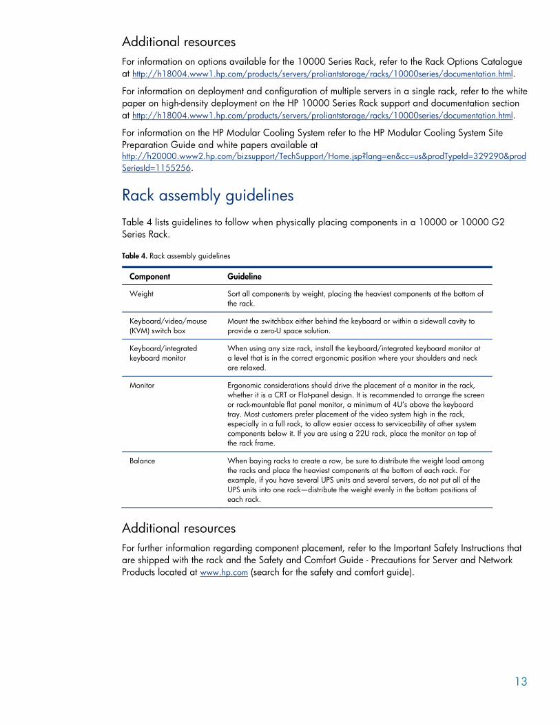
Rack assembly guidelines Table 4 lists guidelines to follow when physically placing components in a 10000 or 10000 G2 Series Rack.
Table 4. Rack assembly guidelines
Component Guideline
Weight Sort all components by weight, placing the heaviest components at the bottom of the rack.
Keyboard/video/mouse (KVM) switch box
Mount the switchbox either behind the keyboard or within a sidewall cavity to provide a zero-U space solution.
Keyboard/integrated keyboard monitor
When using any size rack, install the keyboard/integrated keyboard monitor at a level that is in the correct ergonomic position where your shoulders and neck are relaxed.
Monitor Ergonomic considerations should drive the placement of a monitor in the rack, whether it is a CRT or Flat-panel design. It is recommended to arrange the screen or rack-mountable flat panel monitor, a minimum of 4U’s above the keyboard tray. Most customers prefer placement of the video system high in the rack, especially in a full rack, to allow easier access to serviceability of other system components below it. If you are using a 22U rack, place the monitor on top of the rack frame.
Balance When baying racks to create a row, be sure to distribute the weight load among the racks and place the heaviest components at the bottom of each rack. For example, if you have several UPS units and several servers, do not put all of the UPS units into one rack—distribute the weight evenly in the bottom positions of each rack.
Additional resources For further information regarding component placement, refer to the Important Safety Instructions that are shipped with the rack and the Safety and Comfort Guide - Precautions for Server and Network Products located at www.hp.com (search for the safety and comfort guide).
14
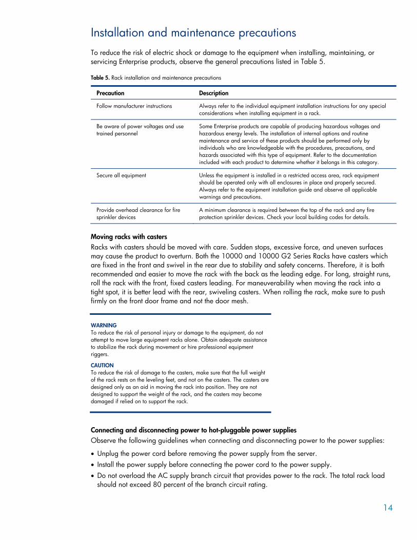
Installation and maintenance precautions To reduce the risk of electric shock or damage to the equipment when installing, maintaining, or servicing Enterprise products, observe the general precautions listed in Table 5.
Table 5. Rack installation and maintenance precautions
Precaution Description
Follow manufacturer instructions Always refer to the individual equipment installation instructions for any special considerations when installing equipment in a rack.
Be aware of power voltages and use trained personnel
Some Enterprise products are capable of producing hazardous voltages and hazardous energy levels. The installation of internal options and routine maintenance and service of these products should be performed only by individuals who are knowledgeable with the procedures, precautions, and hazards associated with this type of equipment. Refer to the documentation included with each product to determine whether it belongs in this category.
Secure all equipment Unless the equipment is installed in a restricted access area, rack equipment should be operated only with all enclosures in place and properly secured. Always refer to the equipment installation guide and observe all applicable warnings and precautions.
Provide overhead clearance for fire sprinkler devices
A minimum clearance is required between the top of the rack and any fire protection sprinkler devices. Check your local building codes for details.
Moving racks with casters Racks with casters should be moved with care. Sudden stops, excessive force, and uneven surfaces may cause the product to overturn. Both the 10000 and 10000 G2 Series Racks have casters which are fixed in the front and swivel in the rear due to stability and safety concerns. Therefore, it is both recommended and easier to move the rack with the back as the leading edge. For long, straight runs, roll the rack with the front, fixed casters leading. For maneuverability when moving the rack into a tight spot, it is better lead with the rear, swiveling casters. When rolling the rack, make sure to push firmly on the front door frame and not the door mesh.
WARNING To reduce the risk of personal injury or damage to the equipment, do not attempt to move large equipment racks alone. Obtain adequate assistance to stabilize the rack during movement or hire professional equipment riggers.
CAUTION To reduce the risk of damage to the casters, make sure that the full weight of the rack rests on the leveling feet, and not on the casters. The casters are designed only as an aid in moving the rack into position. They are not designed to support the weight of the rack, and the casters may become damaged if relied on to support the rack.
Connecting and disconnecting power to hot-pluggable power supplies Observe the following guidelines when connecting and disconnecting power to the power supplies:
• Unplug the power cord before removing the power supply from the server. • Install the power supply before connecting the power cord to the power supply. • Do not overload the AC supply branch circuit that provides power to the rack. The total rack load
should not exceed 80 percent of the branch circuit rating.
15
Rack-mountable products Because computer components are stacked vertically in a rack, adhere to the following precautions to ensure rack stability:
• Use the configuration you prepared with the HP eCo-Enterprise Configurator as a guideline for installing the components.
• Load heavier components first and load the rack from the bottom up. • When coupling or baying racks, be sure to balance the weight load between or among the racks,
placing the heaviest components at the bottom. For example, if you have several UPS units and several servers, do not put all of the UPS units into one rack—distribute them evenly in the bottom positions among the racks.
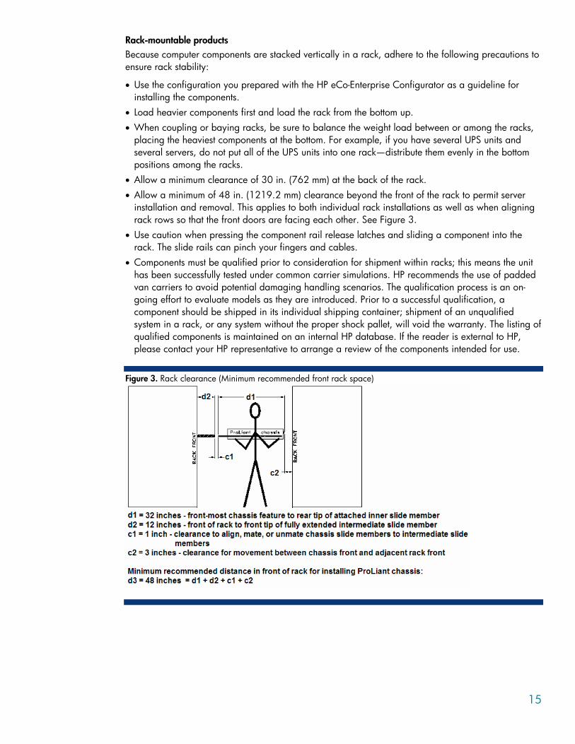
• Allow a minimum clearance of 30 in. (762 mm) at the back of the rack. • Allow a minimum of 48 in. (1219.2 mm) clearance beyond the front of the rack to permit server
installation and removal. This applies to both individual rack installations as well as when aligning rack rows so that the front doors are facing each other. See Figure 3.
• Use caution when pressing the component rail release latches and sliding a component into the rack. The slide rails can pinch your fingers and cables.
• Components must be qualified prior to consideration for shipment within racks; this means the unit has been successfully tested under common carrier simulations. HP recommends the use of padded van carriers to avoid potential damaging handling scenarios. The qualification process is an on-going effort to evaluate models as they are introduced. Prior to a successful qualification, a component should be shipped in its individual shipping container; shipment of an unqualified system in a rack, or any system without the proper shock pallet, will void the warranty. The listing of qualified components is maintained on an internal HP database. If the reader is external to HP, please contact your HP representative to arrange a review of the components intended for use.
Figure 3. Rack clearance (Minimum recommended front rack space)

16
WARNING To reduce the risk of personal injury or damage to the equipment, be sure that the rack is stabilized as follows:
• The leveling feet are extended to the floor.
• The full weight of the rack rests on the leveling feet.
• The stabilizing feet are attached to the rack if it is a single-rack installation.
• The racks are coupled together in multiple-rack installations.
• Extend only one component at a time or the rack may become unstable.
Data Center planning and considerations
Environmental considerations The data center must meet certain environmental conditions for the rack implementation.
Thermal considerations The racks should be configured and arranged in a data center to ensure proper air flow. Configuring a rack for proper air flow
The increasing power of new high-performance processor technology requires increased cooling efficiency for rack-mounted servers. The 10000 Series Racks provide enhanced air flow for maximum cooling, allowing these racks to be loaded with a maximum of 8–10 KW. For extreme cases, refer to www.hp.com/go/mcs.
CAUTION It is necessary to ensure that the components installed in the rack do not exceed the Manufacturer's Maximum Recommended Ambient Operating Temperature.
Rack openings and perforations
Slots, openings and perforations in the rack (especially in doors) provide ventilation, reliable operation, and prevent overheating and, therefore, should never be blocked or covered. To provide proper front-to-back air flow, any open "U" space in the front of a rack must be covered with a HP 10000 Series Universal Filler Panel.
CAUTION Failure to cover open U spaces with blanking panels may result in improper cooling that can lead to thermal damage.
Back-pressure air flow condition
Certain rack configurations, such as racks with extreme cable or server density, may cause a back-pressure situation to occur. When a back-pressure situation occurs, heated exhaust air is forced around the side of the server components and back into the server inlet. Contact an Authorized Service Provider if you suspect a back-pressure situation is occurring in a rack.
17
Configuring racks without air flow perforations
Older rack series, such as the Rack 7000 Series Racks and third-party racks with glass doors must have the door removed to support the latest high-performance equipment. Components should not be installed in a built-up enclosure unless the following conditions have been met:
• The enclosure is specifically designed to accommodate the component. • There is proper ventilation for the component. • All manufacturer instructions have been followed.
Rack placement and arrangement for proper air flow
Racks must be placed and arranged properly in the data center to provide sufficient air flow and clearance for access to the rack.
In the front of the rack, a clearance of 48 in. (1219 mm) is required; this applies to individual rack installations as well as when aligning rack rows so that the front doors are facing each other.
In the rear of the rack, a clearance of 30 in. (762 mm) is required to provide space for servicing the rack.
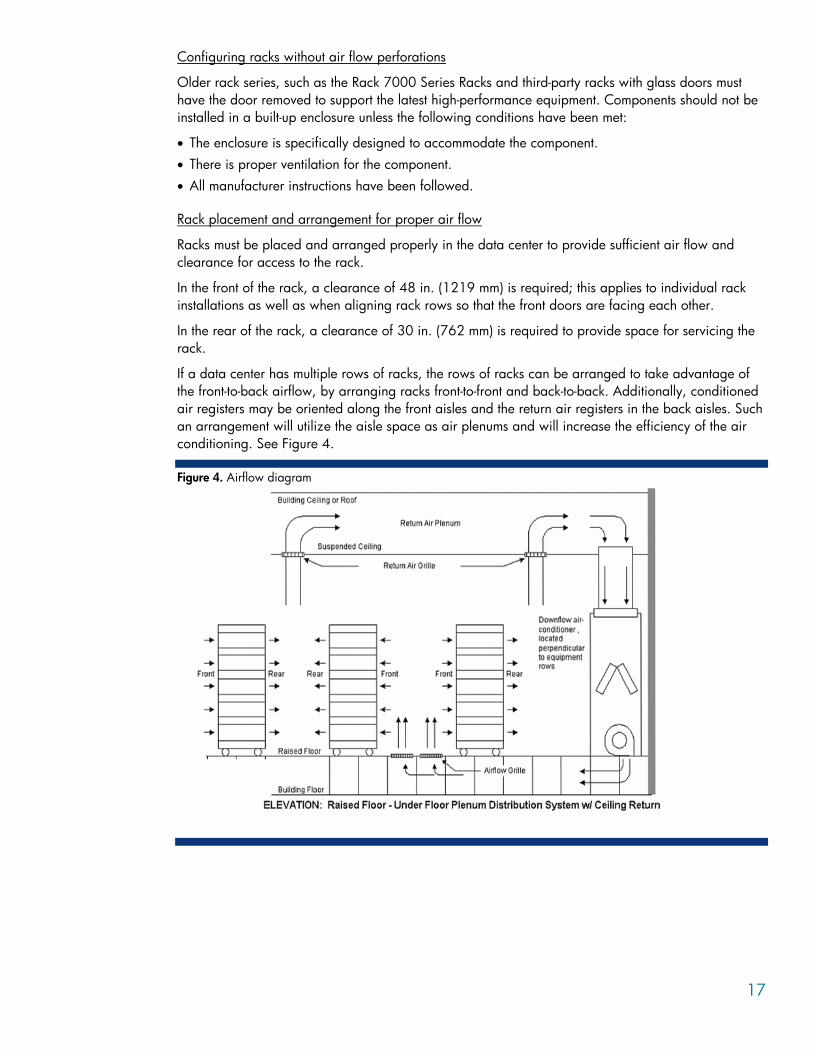
If a data center has multiple rows of racks, the rows of racks can be arranged to take advantage of the front-to-back airflow, by arranging racks front-to-front and back-to-back. Additionally, conditioned air registers may be oriented along the front aisles and the return air registers in the back aisles. Such an arrangement will utilize the aisle space as air plenums and will increase the efficiency of the air conditioning. See Figure 4.
Figure 4. Airflow diagram
18
Data center temperature and humidity
The data center temperature and humidity should meet the guidelines listed in Table 6.
Table 6. Temperature and humidity specifications
Type Operating Non-operating
Temperature 50 to 90° F (10 to 35° C) at sea level -22 to 140° F (-30 to 60° C)
Humidity 10 to 90% non-condensing 5 to 90% non-condensing
NOTE Altitude derating of 1o C for every 300 meters above sea level to a maximum of 3,000 meters (1.8 o F per every 1,000 feet up to a maximum of 10,000 feet). No direct sustained sunlight.
Third-party thermal considerations
CAUTION If a third-party rack is used, observe the following additional requirements to ensure adequate airflow and to prevent damage to the equipment: • Front and rear doors: If the 42U server rack includes closing front
and rear doors, allow 830 square inches (5,350 sq cm) of hole evenly distributed from top to bottom to permit adequate airflow (equivalent to the required 64 percent open area for ventilation). Be sure that the option equipment does not impede airflow to the rack-mountable servers or increase the internal rack temperature beyond the specified maximum rating.
• Side: The clearance between the installed rack component and the side panels of the rack must be a minimum of 2.75 inches (7 cm).
CAUTION Always use blanking or filler panels to fill all remaining empty front panel U-spaces in the rack. This arrangement ensures proper airflow. Using a rack without installing blanking panels to fill empty U-spaces results in improper cooling that can lead to thermal damage.
CAUTION Be sure that the option equipment installed does not exceed the Manufacturer’s Maximum Recommended Ambient Operating Temperature.
NOTE For additional information, refer to the Setup and Installation Guide or the Documentation CD provided with the server, or to the server documentation located in the Support section at the following URL: www.hp.com/servers/proliantdl380.
For additional information on data center best practices, see the “Powering the data center efficiently” available at: http://h20000.www2.hp.com/bc/docs/support/SupportManual/c00099859/c00099859.pdf.

19
Power considerations Power is best managed within the rack by the use of a power distribution unit (PDU). Depending on the configuration, it may be necessary or desirable to use multiple PDUs to connect all devices inside the rack.
Each PDU should be connected to a dedicated (unshared) branch circuit that is suitably rated for the continuous load of all the equipment connected to it. The total power load for a PDU should not exceed 80 percent of the branch circuit rating.
If a PDU is not used, each piece of equipment within the rack should be connected to a dedicated branch circuit.
Power redundancy High-availability Information Technology equipment such as servers and storage devices can be configured with backup or redundant power sources and power supplies in either of the following configurations:
• 1+1 design: Two power supplies can be provided where either power supply is capable of sustaining the associated equipment’s power demand.
• N+1 design: Typically three power supplies are provided, requiring at least two to handle the equipment’s power demand. If one fails, the other two remain on line with enough capacity to meet the power demand.
It is important that the wiring and branch circuitry to each installation be suitably rated for the power demand of the connected equipment. Routing the power through separate branch circuits, breaker panels and PDUs is also recommended to provide additional redundancy.
Non-redundant For equipment provided with a single source of power, all components should be connected to the same power distribution device (PDU or UPS). The power distribution device should be suitably rated for the connected load. If the total load exceeds the rating of the power distribution device, obtain a suitably rated device or add a second power distribution device and divide the load equally between the devices.
High line voltage versus low line voltage HP recommends that rack-optimized equipment is installed for operating at high line voltage (200-240V AC).
All HP products that are optimized for rack mounting have wide-range power supply inputs designed to operate at a voltage range of 100--240V.
Benefits that support high line voltage operation of an installation are as follows:
• Power supplies run more efficiently and waste less power when operating at 200--240V, thus saving electrical power.
• Greater power capacity in a single rack. For the same size circuit, almost twice the power can be delivered to a rack at high line versus low line. For example, an 115V 30A branch circuit can deliver 3450VA to a rack, while a 230V 30A branch can deliver 6900 VA to a rack.
• Some products require 200-240V input power to operate at their full-rated capacity. • Power supplies run cooler at higher input voltages and therefore will last longer and improve
overall availability. Also, because they run cooler, they produce less waste heat contributing to lower cooling costs.
• Keeping input currents lower allows the use of smaller, more standardized power connections.

20
Grounding and Earth leakage current For proper operation and safety, rack components must be properly grounded in accordance with any local and regional building codes. Furthermore, make sure that all power distribution devices used in the installation, such as branch wiring and receptacles, are Listed or Certified grounding-type devices.
Because of the high ground-leakage currents associated with multiple servers connected to the same power source, a reliable grounded (earthed) connection is essential. HP recommends the use of a PDU that is either permanently wired to the building’s branch circuit or is provided with a non-detachable cord that is wired to an industrial style plug. National Electrical Manufacturers Association (NEMA) locking-style plugs or those complying with International Electro technical Commission (IEC) 60309 are considered suitable for this purpose. HP does not recommend using common power outlet strips for this equipment.
Observe the following limits when connecting the product to AC power distribution devices:
• For UPS products and PDUs that have permanently attached AC power cords or are directly wired to the building power, the total combined leakage current should not exceed 5 percent of the total input current required for the connected products.
• For UPS products and PDUs that have detachable AC power cords, the total combined leakage current should not exceed 3.5 mA per PDU or UPS.
Additional resources A power calculator is available at http://h30099.www3.hp.com/configurator/calc/Power Calculator Catalog.xls.
Also available is a ProLiant Rack/Site Installation Utility for purposes of reviewing the server loading to determine the number of power supplies for the power supplies to be redundant and approximate the electrical and heating load per server for facilities planning. The ProLiant Rack/Site Installation Utility is available at http://h30099.www3.hp.com/configurator/calc/Site Preparation Utility.xls.
There is also a quick reference power cord matrix available at ftp://ftp.compaq.com/pub/products/servers/proliantstorage/power-protection/powercordmatrix.pdf.
Equipment clearance and floor loading A clearance of 48 inches in front of a configured rack and 30 inches to the rear of a configured rack is recommended. All buildings and raised computer room floors are engineered to provide a specific floor loading.
WARNING When configuring a solution, make sure that the floor loading specifications are followed. Failure to do so may result in physical injury or damage to the equipment and the facility.
21
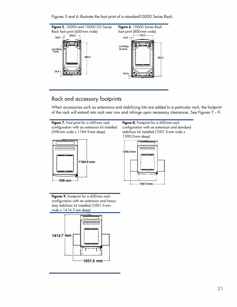
Figures 5 and 6 illustrate the foot print of a standard10000 Series Rack.
Figure 5. 10000 and 10000 G2 Series Rack foot print (600-mm wide)
Figure 6. 10000 Series Rack foot print (800-mm wide)
Rack and accessory footprints When accessories such as extensions and stabilizing kits are added to a particular rack, the footprint of the rack will extend into rack rear row and infringe upon necessary clearances. See Figures 7 -- 9.
Figure 7. Foot print for a 600-mm rack configuration with an extension kit installed (598-mm wide x 1184.9-mm deep)
Figure 8. Footprint for a 600-mm rack configuration with an extension and standard stabilizer kit installed (1001.5-mm wide x 1390.0-mm deep)
Figures 9. Footprint for a 600-mm rack configuration with an extension and heavy duty stabilizer kit installed (1001.5-mm wide x 1414.7-mm deep)
22
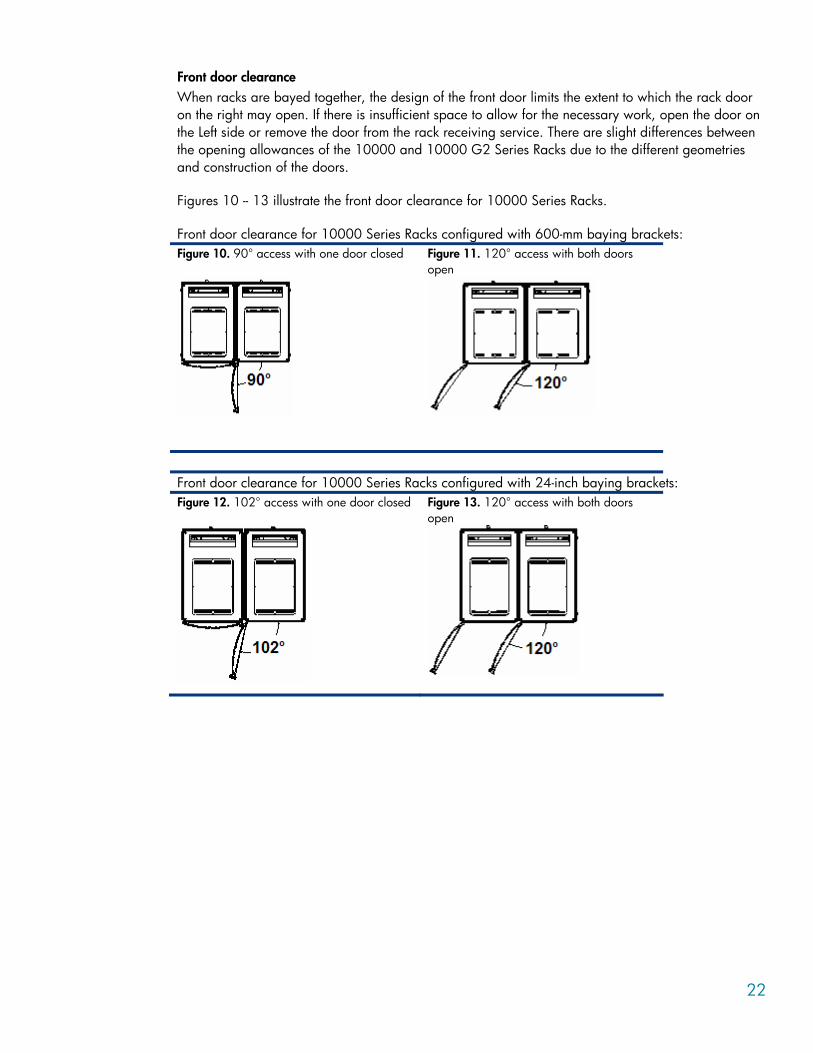
Front door clearance When racks are bayed together, the design of the front door limits the extent to which the rack door on the right may open. If there is insufficient space to allow for the necessary work, open the door on the Left side or remove the door from the rack receiving service. There are slight differences between the opening allowances of the 10000 and 10000 G2 Series Racks due to the different geometries and construction of the doors.
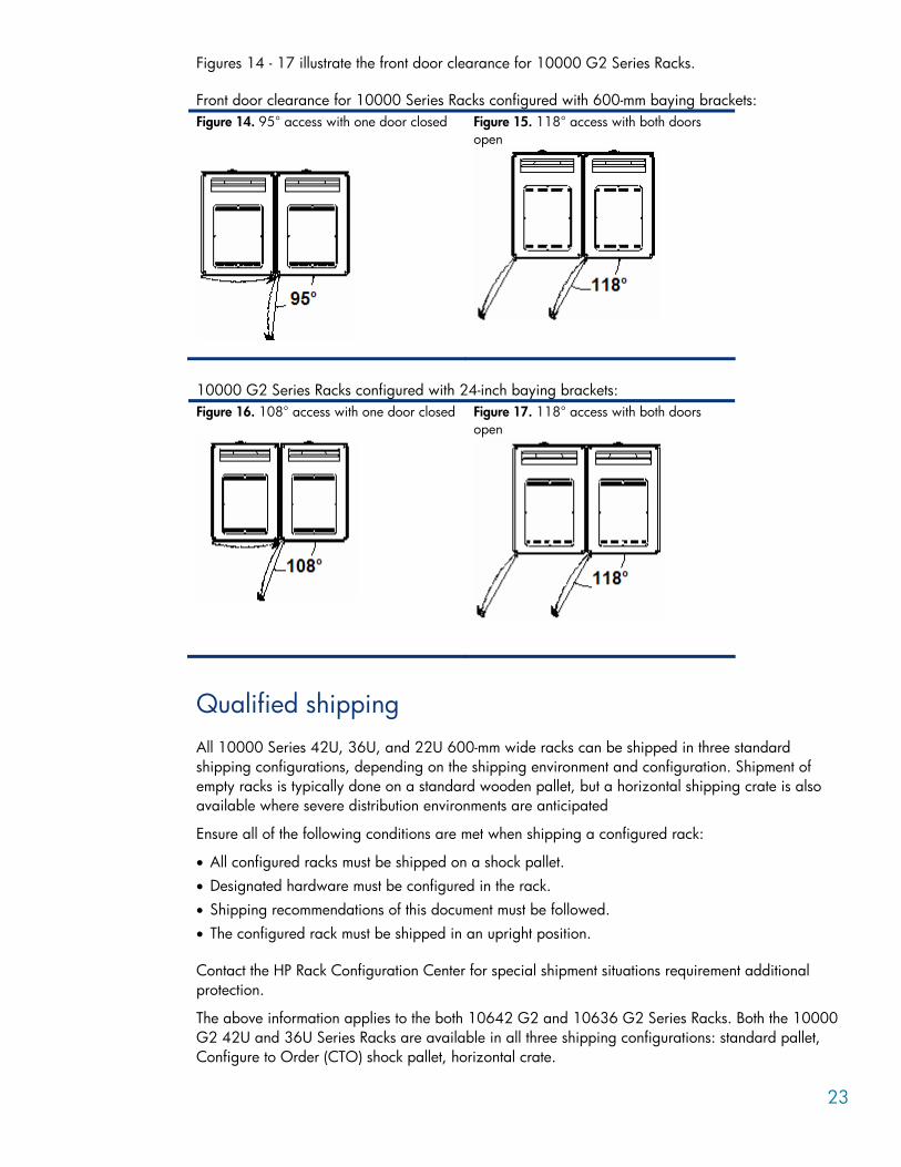
Figures 10 -- 13 illustrate the front door clearance for 10000 Series Racks.
Front door clearance for 10000 Series Racks configured with 600-mm baying brackets: Figure 10. 90° access with one door closed Figure 11. 120° access with both doors
open
Front door clearance for 10000 Series Racks configured with 24-inch baying brackets: Figure 12. 102° access with one door closed Figure 13. 120° access with both doors
open
23
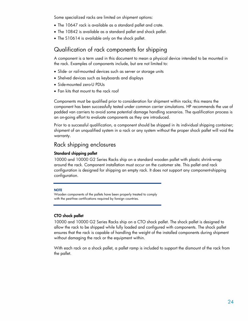
Figures 14 - 17 illustrate the front door clearance for 10000 G2 Series Racks.
Front door clearance for 10000 Series Racks configured with 600-mm baying brackets: Figure 14. 95° access with one door closed Figure 15. 118° access with both doors
open
10000 G2 Series Racks configured with 24-inch baying brackets: Figure 16. 108° access with one door closed Figure 17. 118° access with both doors
open
Qualified shipping All 10000 Series 42U, 36U, and 22U 600-mm wide racks can be shipped in three standard shipping configurations, depending on the shipping environment and configuration. Shipment of empty racks is typically done on a standard wooden pallet, but a horizontal shipping crate is also available where severe distribution environments are anticipated
Ensure all of the following conditions are met when shipping a configured rack:
• All configured racks must be shipped on a shock pallet. • Designated hardware must be configured in the rack. • Shipping recommendations of this document must be followed. • The configured rack must be shipped in an upright position.
Contact the HP Rack Configuration Center for special shipment situations requirement additional protection.
The above information applies to the both 10642 G2 and 10636 G2 Series Racks. Both the 10000 G2 42U and 36U Series Racks are available in all three shipping configurations: standard pallet, Configure to Order (CTO) shock pallet, horizontal crate.
24
Some specialized racks are limited on shipment options:
• The 10647 rack is available as a standard pallet and crate. • The 10842 is available as a standard pallet and shock pallet. • The S10614 is available only on the shock pallet.
Qualification of rack components for shipping A component is a term used in this document to mean a physical device intended to be mounted in the rack. Examples of components include, but are not limited to:
• Slide- or rail-mounted devices such as server or storage units • Shelved devices such as keyboards and displays • Side-mounted zero-U PDUs • Fan kits that mount to the rack roof
Components must be qualified prior to consideration for shipment within racks; this means the component has been successfully tested under common carrier simulations. HP recommends the use of padded van carriers to avoid some potential damage handling scenarios. The qualification process is an on-going effort to evaluate components as they are introduced.
Prior to a successful qualification, a component should be shipped in its individual shipping container; shipment of an unqualified system in a rack or any system without the proper shock pallet will void the warranty.
Rack shipping enclosures Standard shipping pallet 10000 and 10000 G2 Series Racks ship on a standard wooden pallet with plastic shrink-wrap around the rack. Component installation must occur on the customer site. This pallet and rack configuration is designed for shipping an empty rack. It does not support any component-shipping configuration.
NOTE Wooden components of the pallets have been properly treated to comply with the pest-free certifications required by foreign countries.
CTO shock pallet 10000 and 10000 G2 Series Racks ship on a CTO shock pallet. The shock pallet is designed to allow the rack to be shipped while fully loaded and configured with components. The shock pallet ensures that the rack is capable of handling the weight of the installed components during shipment without damaging the rack or the equipment within.
With each rack on a shock pallet, a pallet ramp is included to support the dismount of the rack from the pallet.
25
NOTE Each of the packing and unpacking procedures takes less than one-half hour and requires at least two people to complete.
NOTE The 10000 and 10000 G2 Series Racks use different shock pallets. If a rear extension is installed on the 10000 G2 Series Rack, a specific shock pallet is required to accommodate the dimensions of the rack and attached rear extension. The 10000 Series Rack with extension is not supported in the CTO shipping environment.
An HP shock pallet spares kit is recommended and can be obtained when moving a data center or relocating pre-configured racks. Contact your local HP reseller for information on spares kits.
NOTE The 10000 Series Rack Model 10647 is not available on a shock pallet due to safety and stability concerns.
NOTE All wood components of these pallets have been properly treated to comply with the pest-free certifications required by foreign countries.
Horizontal crate 10000 and 10000 G2 Series Racks ship in an enclosed horizontal crate. The enclosed horizontal crate provides greater protection for the empty rack during airfreight transport and other rugged transportation modes.
NOTE Horizontally crated racks do NOT support configured racks.
NOTE The 10000 Series Rack Models S10614 and 10842 are not available for shipment in a horizontally crate.
Vertical crate for rack options If specially ordered, 10000 G2 Series 42U and 36U racks can be shipped in a vertical crate. The rack must include factory installed option in the customer order to qualify for shipment in the vertical crate. The rack ships on a CTO shock pallet and is enclosed in a wooden crate. The vertical crate provides greater protection for the configured rack during airfreight transport and other rugged transportation modes.
NOTE All wood components of these pallets have been properly treated to comply with the pest-free certifications required by foreign countries.
26
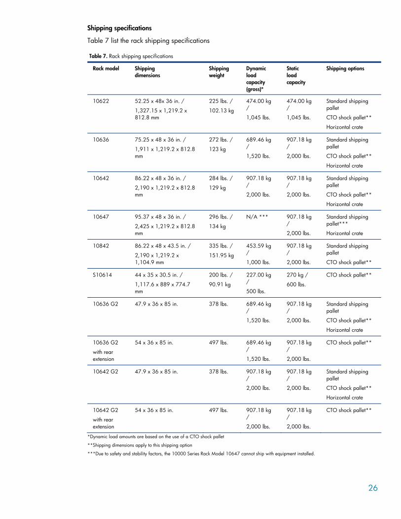
Shipping specifications
Table 7 list the rack shipping specifications
Table 7. Rack shipping specifications
Rack model Shipping dimensions
Shipping weight
Dynamic load capacity (gross)*
Static load capacity
Shipping options
10622 52.25 x 48x 36 in. /
1,327.15 x 1,219.2 x 812.8 mm
225 lbs. /
102.13 kg
474.00 kg /
1,045 lbs.
474.00 kg /
1,045 lbs.
Standard shipping pallet
CTO shock pallet**
Horizontal crate
10636 75.25 x 48 x 36 in. /
1,911 x 1,219.2 x 812.8 mm
272 lbs. /
123 kg
689.46 kg /
1,520 lbs.
907.18 kg /
2,000 lbs.
Standard shipping pallet
CTO shock pallet**
Horizontal crate
10642 86.22 x 48 x 36 in. /
2,190 x 1,219.2 x 812.8 mm
284 lbs. /
129 kg
907.18 kg /
2,000 lbs.
907.18 kg /
2,000 lbs.
Standard shipping pallet
CTO shock pallet**
Horizontal crate
10647 95.37 x 48 x 36 in. /
2,425 x 1,219.2 x 812.8 mm
296 lbs. /
134 kg
N/A *** 907.18 kg /
2,000 lbs.
Standard shipping pallet***
Horizontal crate
10842 86.22 x 48 x 43.5 in. /
2,190 x 1,219.2 x 1,104.9 mm
335 lbs. /
151.95 kg
453.59 kg /
1,000 lbs.
907.18 kg /
2,000 lbs.
Standard shipping pallet
CTO shock pallet**
S10614 44 x 35 x 30.5 in. /
1,117.6 x 889 x 774.7 mm
200 lbs. /
90.91 kg
227.00 kg /
500 lbs.
270 kg /
600 lbs.
CTO shock pallet**
10636 G2 47.9 x 36 x 85 in. 378 lbs. 689.46 kg /
1,520 lbs.
907.18 kg /
2,000 lbs.
Standard shipping pallet
CTO shock pallet**
Horizontal crate
10636 G2
with rear extension
54 x 36 x 85 in. 497 lbs. 689.46 kg /
1,520 lbs.
907.18 kg /
2,000 lbs.
CTO shock pallet**
10642 G2 47.9 x 36 x 85 in. 378 lbs. 907.18 kg /
2,000 lbs.
907.18 kg /
2,000 lbs.
Standard shipping pallet
CTO shock pallet**
Horizontal crate
10642 G2
with rear extension
54 x 36 x 85 in. 497 lbs. 907.18 kg /
2,000 lbs.
907.18 kg /
2,000 lbs.
CTO shock pallet**
*Dynamic load amounts are based on the use of a CTO shock pallet
**Shipping dimensions apply to this shipping option
***Due to safety and stability factors, the 10000 Series Rack Model 10647 cannot ship with equipment installed.
27
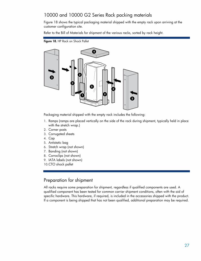
10000 and 10000 G2 Series Rack packing materials Figure 18 shows the typical packaging material shipped with the empty rack upon arriving at the customer configuration site.
Refer to the Bill of Materials for shipment of the various racks, sorted by rack height.
Figure 18. HP Rack on Shock Pallet
1
2
4
3
5
2
2
2
3
4
Packaging material shipped with the empty rack includes the following:
1. Ramps (ramps are placed vertically on the side of the rack during shipment, typically held in place with the stretch wrap.)
2. Corner posts 3. Corrugated sheets 4. Cap 5. Antistatic bag 6. Stretch wrap (not shown) 7. Banding (not shown) 8. Corroclips (not shown) 9. IATA labels (not shown) 10. CTO shock pallet
Preparation for shipment All racks require some preparation for shipment, regardless if qualified components are used. A qualified component has been tested for common carrier shipment conditions, often with the aid of specific hardware. This hardware, if required, is included in the accessories shipped with the product. If a component is being shipped that has not been qualified, additional preparation may be required.
28
Site preparation for receiving Integrated Racks To determine if a configured rack is suitable for shipment, be sure to examine the receiving facility site conditions. Circumstances requiring special handling of the rack, such as inadequate door height clearance or having to move the rack in a horizontal orientation, may justify a decision to install components after the moving process.
The specialized, air-ride, padded-van carriers usually have the ability to perform site surveys.
Among other elements, the site survey should address the following in general terms:
• What are the hours the facility is open for deliveries? Can delivery be done during the day during normal business hours?
• Are appointments required? • Does the receiving dock require union labor? Is there a site contact? • Are there any security or building access issues? Is there a site contact? • Does the facility have a dock? Is the delivery dock a standard raised dock? Can a 48-foot trailer
gain access? Are there any restrictions on the size, length, width or height, of the truck permitted? • On what floor in building will the equipment be installed? This information is in consideration of
height and width clearances along the way: doors, light fixtures, cable trays, sprinkler heads, elevators, etc.
• What are the door height clearances (width and height) for freight elevators, doorways, or other obstacles?
• If equipment is not going on the first floor, is there an elevator? If yes, what is the weight capacity of the elevator?
• Is the path from the loading dock to the computer room robust enough to support the weight of the configured rack?
• Is there a delivery/unpacking/staging area? Does the customer allow cardboard boxes and/or other packing material in the computer room? Does the customer have a detrash requirement, for example is complete trash removal 1 or 2 days after install required?
• Is there a raised floor or are there any thresholds of concern? If there is a raised floor, how deep? Is there a ramp? What sort of equipment maneuvering is required to gain access? Are there special equipment needs, for example, will any stair walkers, lifters, cranes, ramps, steel plates or floor covers be required to place the equipment in the computer room?
NOTE HP does not advocate tipping loaded racks to navigate height restricted doorways.
• Will the rack be removed from the pallet at a location other than the final installation location? • Is movement across rough surfaces likely?
General considerations (all shipments)
Before beginning these procedures, please understand and follow these precautions.
29
WARNING To reduce the risk of personal injury or damage to the equipment, prior to shipping, remove all non-rack-mounted equipment, including any component that is not mechanically fastened to the rack structure.
The following are the minimum requirements for qualifying components for shipment in a HP 10000 and 10000 G2 Racks mounted on a CTO shock pallet:
• The shock pallet is a 1-way pallet and should not be reused. Reuse of a cushioned pallet may not protect the rack and server components in transit. If a datacenter or loaded rack move is being scheduled, it is strongly recommended that the shock pallet spares kit is purchased as well as all safety considerations be addressed. For a complete list of HP rack options and accessories, refer to the main rack page at www.hp.com/products/racks or to the main rack options page at www.hp.com/products/rackoptions.
• Use a torque wrench to tighten all front panel mounting hardware and rail/slide connections to 20 in-lb. (2.2594 N-m). Use provided mounting hardware to secure any spring-loaded slide assemblies to the mounting rails.
• Use the shipping hardware or additional clamping or hold-down brackets provided with each component. This hardware is typically found in the accessory box. The Server Immobilization Bolt (SIB) is a large orange thumbscrew and is easily installed from the rear of the rack.
• Dress and secure all data and power cables. Cables and cable management arms should be tie-wrapped to prevent movement of cables that may place a load on connector assemblies or that may cause fraying due to friction. Wire-formed cable management clamps are provided with each rack for this purpose. Some components provide sheet metal cable management extensions or spring loaded cable retention reels that should be utilized in all cases. Firmly close front and rear doors.
• Reuse any packaging materials that were initially provided with the rack. • Check to ensure the rack mounting brackets are properly secured to the pallet. The bracket with
keyhole cutouts should be at an angle to the pallet deck and should not be loose. The front hold downs for 10000 G2 Series Racks are right-angled and sit flush to the pallet and frame. Ensure that the bolt securing the bracket to the pallet is torqued to 150 in-lb (16.9 N-m).
• All racks should be secured in the trailer/truck to prevent the rack from potentially falling on its side during vehicle turns.
NOTE Since most common carriers are not accustomed nor equipped to perform this function, this detail is particularly important, even if the configuration is common carrier qualified.
Special shipping considerations Additional requirements for nonqualified components for shipment in a HP 10000 and 10000 G2 Series Rack that is mounted on a shock pallet are listed below:
• Replace any wing nuts with hex- or square-head nuts and appropriate locking hardware. • Inspect the rack for unsupported mechanical structures. Look for any cantilevered chassis with little
or no rear support or any large chassis with rails mounted to the extreme top or bottom of the chassis. Be especially attentive to any free movement of the component while mounted in the rack. In some cases, it may be beneficial to use supplemental packaging materials to brace these
30
components. The white foam from the shipping containers of the components works well in these situations.
• Do not ship backup media in either tape drives or in tape library units. • HP UPS systems have been qualified for rack CTO with the exception of the R12000 which has
unique shipping provisions due to its size. Each of these UPS systems may be shipped in a rack provided the system is electrically disconnected from the battery during shipment; each unit comes equipped with the appropriate isolators to comply with this requirement.
• Some shipping regulations require specific identification of the batteries enclosed with the package. For example, the US Department of Transportation requires a pack enclosing a UPS battery be marked to indicate a spill proof lead acid battery was enclosed. For CTO Rack shipments destined for Europe, specific markings of all battery systems are required, including the real-time clock batteries found in each server.
To comply with these requirements, HP provides a family of decals that may be applied to the shipping carton.
WARNING When reinstalling the battery, a spark may be observed when reconnecting the spade terminals. Be sure to hold the connectors by the insulated housing. To prevent rotation of mounting rails, ensure that the front panel mounting screws are in place when reinstalling the battery.
Door Height Clearances
HP does not advocate tipping loaded racks to navigate height restricted doorways. The HP recommended procedure is to first depopulate the rack and then tip the rack to pass the restricted doorway. Once the rack is positioned in its final location, it can be repopulated. This will ensure that rack stability is maintained by not tipping a heavily loaded rack. Depopulating the rack also ensures that the integrity of the components in the rack is not compromised by tipping.
If you have restricted height doorways, you have several alternatives for purchasing HP factory racked solutions that can accommodate the height of the doorways without the need to depopulate the rack.
If you have restricted doorways:
• You can order racked solutions in an appropriate sized rack that can be accommodated by the doorways. Choose the rack size that best meets your datacenter needs while at the same time being able to pass all doorways on the path to the racks final location.
• A 42U rack that is unable to pass fully loaded through the doorway, options include: – Ordering an empty 42U rack and purchasing installation services from HP Services. – For BCS midrange servers with included installation services, you can order an empty 42U 10K
and order the server with the field installation option. • With included site prep service, will recommend to you the best way to locate the system to its final
location.
Modes of shipment HP recommends that you ship all configured racks through a service offering specialized, air-ride, padded-van carriers. Certain carriers may provide operators who are specifically trained for inside deliveries and special handling situations involving electronic equipment; for example, they will routinely carry the strapping needed to secure the rack to the side of the trailer. They are also trained to conduct site surveys, if required.

31
Guidelines for selecting a specialized, air-ride, padded-van carriers include the following considerations:
• A dedicated truck shipment can be set up with no transfer points where the equipment is unloaded/reloaded enroute to its destination.
• These carriers are accustomed to special handling arrangements and will provide any necessary materials.
• The rack assembly is secured within the truck. • Specialized, air-ride, padded-van carriers are required for shipment of any rack with at least one
component that has not been qualified.
Airfreight Because the rack cannot be safely tipped or placed on its side during transit or storage, air cargo doors must have height sufficient for the rack to be loaded and removed without tipping. Consult your freight forwarder for available aircraft configurations that satisfy your particular rack height.
International Air Transport Association labeling Typical HP products that are classified as Magnetized Material are those with arc-welded frames that contain a large mass of ferrous metal. For example, most racks or cabinets will usually test in the low to mid-range of the regulatory limits and be classified as Magnetized Material.
Magnetized Material is regulated as Dangerous Goods under Class 9, “Miscellaneous Dangerous Goods,” and has been assigned the United Nations identification number, UN2807. These goods are only regulated when transported by air due to their potential for interference with aircraft instrumentation. Shipments must be properly marked, labeled and documented to be legally accepted by an air carrier for transport.
For more specific details of how and why this requirement process is managed, please refer to the following URL: www.iata.com.
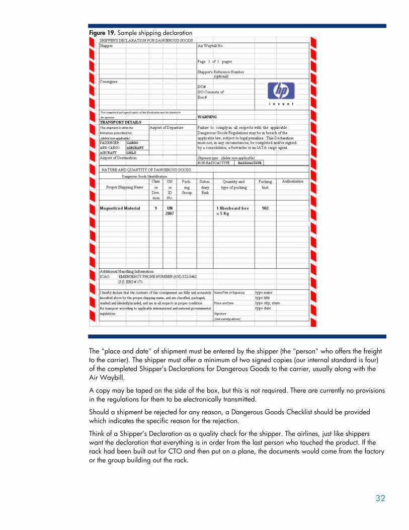
In all cases of air shipments, a Shipper Declaration is required (see Figure 19). This sample is an internal HP document. If access is needed, please ask your local HP service representative to contact the Rack Program management organization within HP.
32
Figure 19. Sample shipping declaration
The "place and date" of shipment must be entered by the shipper (the "person" who offers the freight to the carrier). The shipper must offer a minimum of two signed copies (our internal standard is four) of the completed Shipper's Declarations for Dangerous Goods to the carrier, usually along with the Air Waybill.
A copy may be taped on the side of the box, but this is not required. There are currently no provisions in the regulations for them to be electronically transmitted.
Should a shipment be rejected for any reason, a Dangerous Goods Checklist should be provided which indicates the specific reason for the rejection.
Think of a Shipper’s Declaration as a quality check for the shipper. The airlines, just like shippers want the declaration that everything is in order from the last person who touched the product. If the rack had been built out for CTO and then put on a plane, the documents would come from the factory or the group building out the rack.
33
Mode of receiving and delivery Knowledge of the receiving site is an important planning consideration, as special equipment or arrangements may have to be made. Think about the following issues:
• Inquire whether the receiver has a shipping dock with adequate height for a truck to load and unload the equipment. Without a dock, specialized equipment such as bobtail trucks and forklifts may be required. If the rack is to be rolled across a parking area, panels of plywood or Formica are recommended to minimize the vibration induced into the rack.
• Be aware that the 10642 and 10642 G2 racks are 86 inches (2159 mm) high on the pallet and exceeds standard 7-foot doorways so the rack will have to be de-palletized for passage through the standard 7-foot doorframe.
• The 47U racks cannot be moved with equipment installed due to safety and stability concerns. • Use the shock pallet to ship the rack with equipment installed. Pallet jacks are recommended when
moving the rack inside a building structure. When using a fork lift, access should only be from the front as indicated in the documentation. Pallet jacks may enter from the front or rear; however, front access is preferred for greater stability.
• Consider that alternative handling schemes may be required in areas with elevated floor structures with inadequate ramp systems (for example, lifting the rack with eyebolts in the top frame for floors with an incline greater than 10 degrees). For products with casters, when negotiating any ramp, keep the front of the rack pointed uphill to minimize the possibility of the rack tipping.
WARNING To reduce the risk of personal injury or damage to the equipment, do not attempt to move large equipment racks by yourself. Obtain adequate assistance to stabilize the rack during movement, or hire professional equipment riggers.
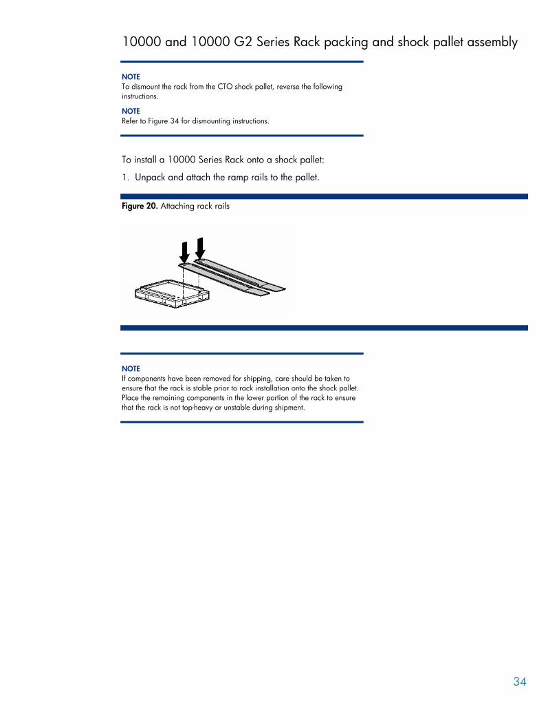
34
10000 and 10000 G2 Series Rack packing and shock pallet assembly
NOTE To dismount the rack from the CTO shock pallet, reverse the following instructions.
NOTE Refer to Figure 34 for dismounting instructions.
To install a 10000 Series Rack onto a shock pallet:
1. Unpack and attach the ramp rails to the pallet.
Figure 20. Attaching rack rails
NOTE If components have been removed for shipping, care should be taken to ensure that the rack is stable prior to rack installation onto the shock pallet. Place the remaining components in the lower portion of the rack to ensure that the rack is not top-heavy or unstable during shipment.
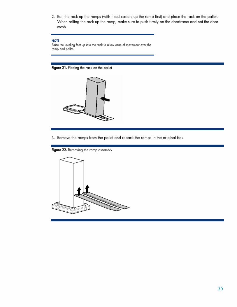
35
2. Roll the rack up the ramps (with fixed casters up the ramp first) and place the rack on the pallet. When rolling the rack up the ramp, make sure to push firmly on the doorframe and not the door mesh.
NOTE Raise the leveling feet up into the rack to allow ease of movement over the ramp and pallet.
Figure 21. Placing the rack on the pallet
3. Remove the ramps from the pallet and repack the ramps in the original box.
Figure 22. Removing the ramp assembly
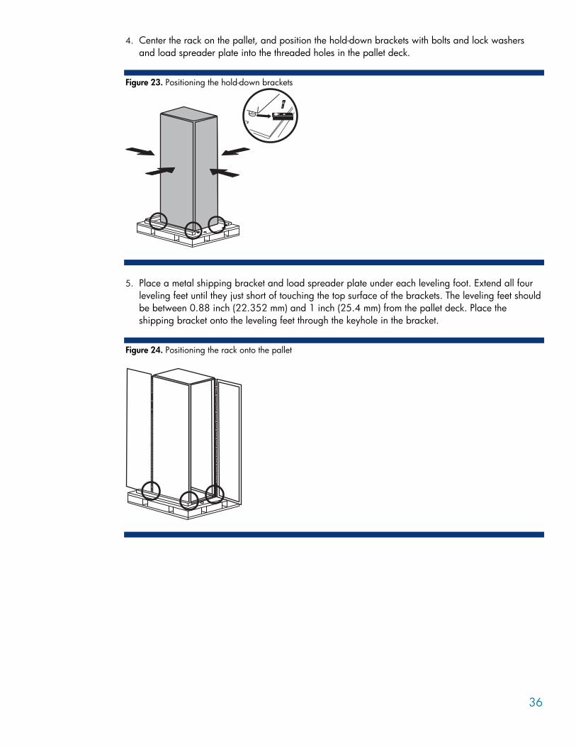
36
4. Center the rack on the pallet, and position the hold-down brackets with bolts and lock washers and load spreader plate into the threaded holes in the pallet deck.
Figure 23. Positioning the hold-down brackets
5. Place a metal shipping bracket and load spreader plate under each leveling foot. Extend all four
leveling feet until they just short of touching the top surface of the brackets. The leveling feet should be between 0.88 inch (22.352 mm) and 1 inch (25.4 mm) from the pallet deck. Place the shipping bracket onto the leveling feet through the keyhole in the bracket.
Figure 24. Positioning the rack onto the pallet
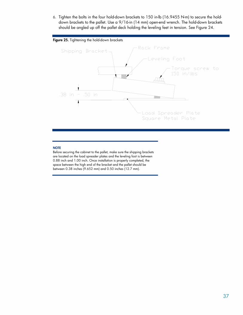
37
6. Tighten the bolts in the four hold-down brackets to 150 in-lb (16.9455 N-m) to secure the hold-down brackets to the pallet. Use a 9/16-in (14 mm) open-end wrench. The hold-down brackets should be angled up off the pallet deck holding the leveling feet in tension. See Figure 24.
Figure 25. Tightening the hold-down brackets
NOTE Before securing the cabinet to the pallet, make sure the shipping brackets are located on the load spreader plates and the leveling foot is between 0.88 inch and 1.00 inch. Once installation is properly completed, the space between the high end of the bracket and the pallet should be between 0.38 inches (9.652 mm) and 0.50 inches (12.7 mm).
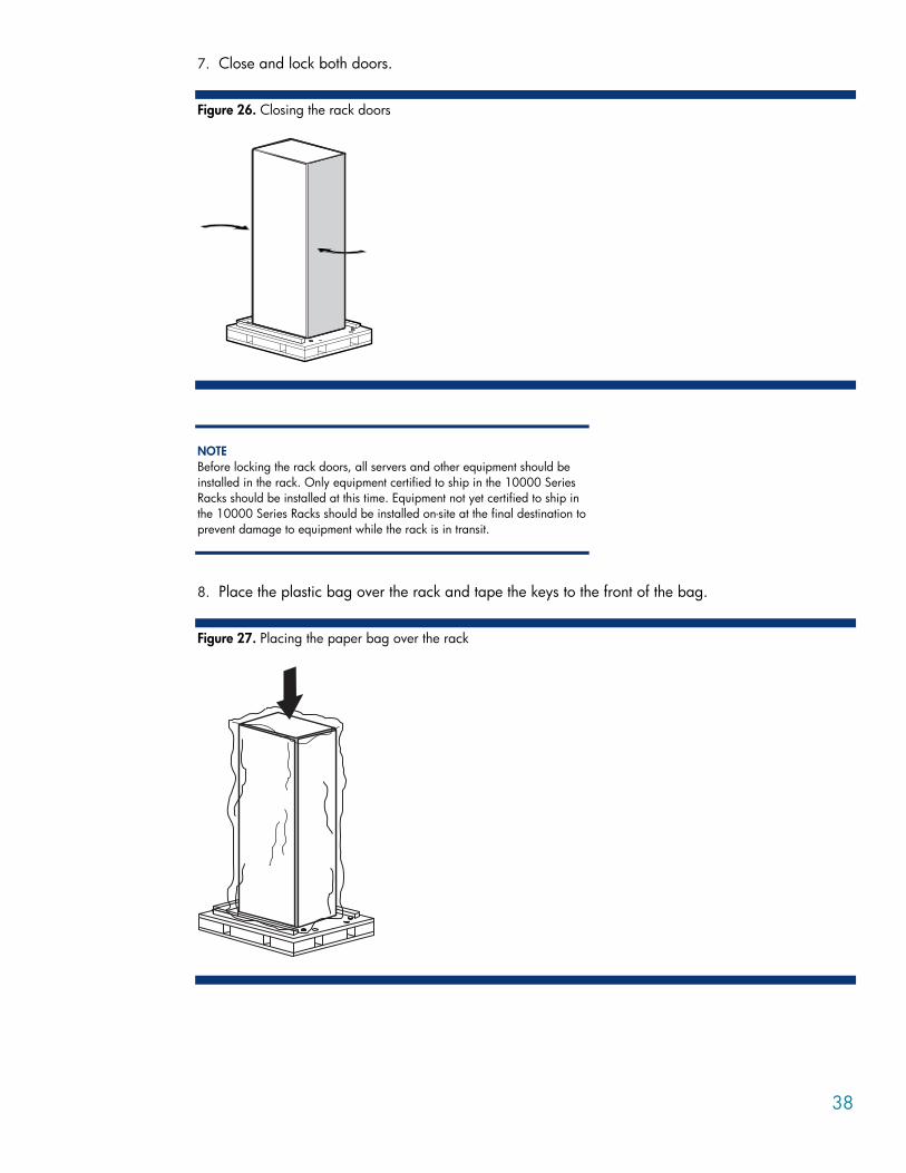
38
7. Close and lock both doors.
Figure 26. Closing the rack doors
NOTE Before locking the rack doors, all servers and other equipment should be installed in the rack. Only equipment certified to ship in the 10000 Series Racks should be installed at this time. Equipment not yet certified to ship in the 10000 Series Racks should be installed on-site at the final destination to prevent damage to equipment while the rack is in transit.
8. Place the plastic bag over the rack and tape the keys to the front of the bag.
Figure 27. Placing the paper bag over the rack
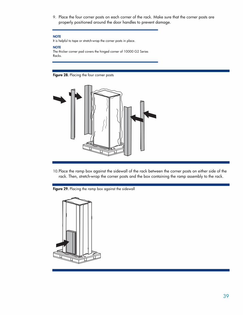
39
9. Place the four corner posts on each corner of the rack. Make sure that the corner posts are properly positioned around the door handles to prevent damage.
NOTE It is helpful to tape or stretch-wrap the corner posts in place.
NOTE The thicker corner pad covers the hinged corner of 10000 G2 Series Racks.
Figure 28. Placing the four corner posts
10. Place the ramp box against the sidewall of the rack between the corner posts on either side of the
rack. Then, stretch-wrap the corner posts and the box containing the ramp assembly to the rack.
Figure 29. Placing the ramp box against the sidewall
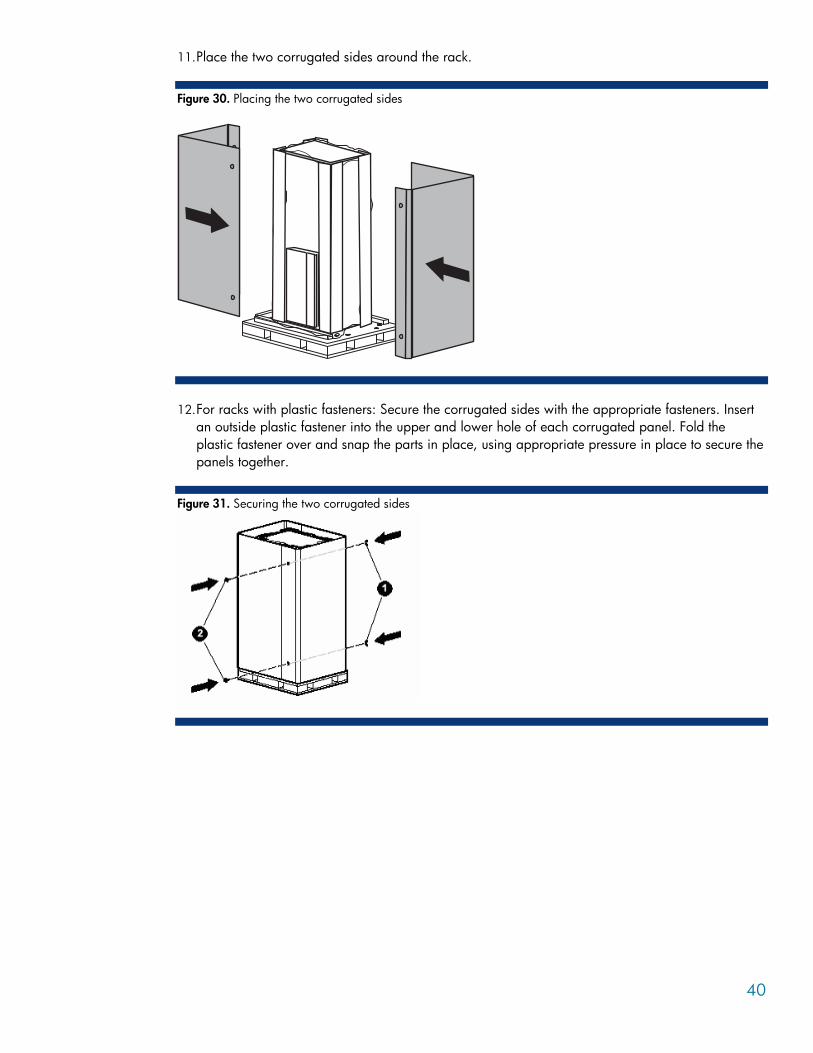
40
11. Place the two corrugated sides around the rack.
Figure 30. Placing the two corrugated sides
12. For racks with plastic fasteners: Secure the corrugated sides with the appropriate fasteners. Insert
an outside plastic fastener into the upper and lower hole of each corrugated panel. Fold the plastic fastener over and snap the parts in place, using appropriate pressure in place to secure the panels together.
Figure 31. Securing the two corrugated sides

41
13. Place the corrugated cap on the top of the assembly.
Figure 32. Placing the box cap
14. Secure the corrugated cap and corrugated sides to the pallet using two applications of banding
running from front to back, and then the installation is complete.
Figure 33. Installed shock pallet
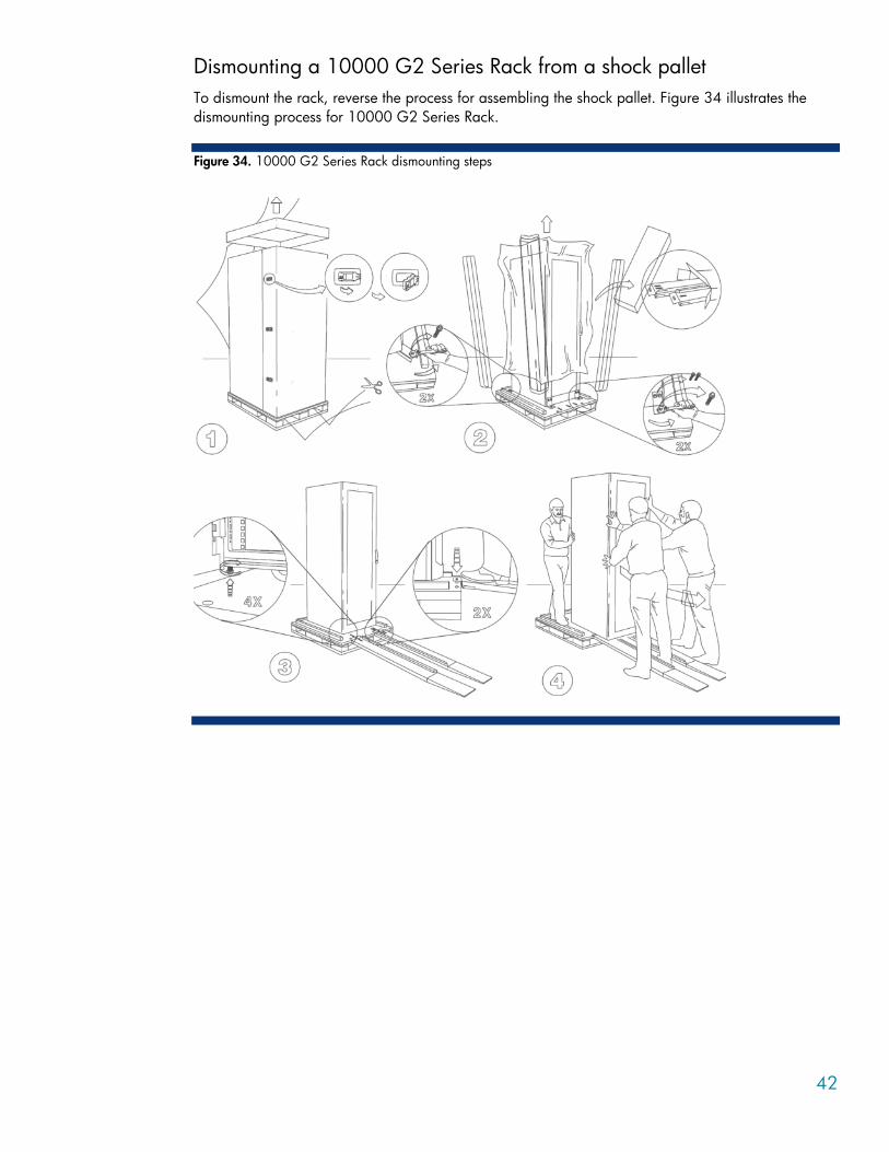
42
Dismounting a 10000 G2 Series Rack from a shock pallet To dismount the rack, reverse the process for assembling the shock pallet. Figure 34 illustrates the dismounting process for 10000 G2 Series Rack.
Figure 34. 10000 G2 Series Rack dismounting steps
43
Installation service In the United States, HP can arrange to have your rack installed by qualified service providers. This installation service covers the entire hardware installation sequence, from unpacking the components to routing cabling and running a test of the systems. Installation can also be provided directly by HP authorized service providers.
If you need a pre-certified solution, contact the high performance technical computing (HPC) solutions group at http://h71028.www7.hp.com/enterprise/cache/284965-0-0-225-121.html.
Spares kits Contact your local reseller for information on spares kits.
Additional tools and equipment • 11/16-in (or 17-mm) open-end wrench • 9/16-in (or 14-mm) open-end wrench or socket • 7/16-in (or 11-mm) open-end wrench or socket • 8/16-in (or 12mm) open-ended wrench or socket • Stretch wrap • Banding
Battery decals and boxes When shipping a battery outside of the UPS, use the packaging provided in the Return Kit Spare. Contact your local reseller for more information.
HP provides a family of decals that may be applied to the shipping carton; these are listed in Table 8.
Table 8. Power products: decals
Part number Decal description
247933-001 Label, Battery Disposal Warning, Cadmium
247933-002 Label, Battery Disposal Warning, Mercury
247933-003 Label, Battery Disposal Warning, Lead Acid
247933-004 Label, Battery Disposal Warning, Other
244014-001 Label, Battery Statement (Non-spill able)
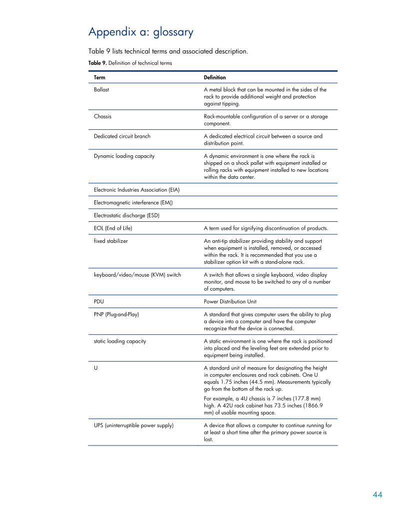
44
Appendix a: glossary Table 9 lists technical terms and associated description.
Table 9. Definition of technical terms
Term Definition
Ballast A metal block that can be mounted in the sides of the rack to provide additional weight and protection against tipping.
Chassis Rack-mountable configuration of a server or a storage component.
Dedicated circuit branch A dedicated electrical circuit between a source and distribution point.
Dynamic loading capacity A dynamic environment is one where the rack is shipped on a shock pallet with equipment installed or rolling racks with equipment installed to new locations within the data center.
Electronic Industries Association (EIA)
Electromagnetic interference (EM()
Electrostatic discharge (ESD)
EOL (End of Life) A term used for signifying discontinuation of products.
fixed stabilizer An anti-tip stabilizer providing stability and support when equipment is installed, removed, or accessed within the rack. It is recommended that you use a stabilizer option kit with a stand-alone rack.
keyboard/video/mouse (KVM) switch A switch that allows a single keyboard, video display monitor, and mouse to be switched to any of a number of computers.
PDU Power Distribution Unit
PNP (Plug-and-Play) A standard that gives computer users the ability to plug a device into a computer and have the computer recognize that the device is connected.
static loading capacity A static environment is one where the rack is positioned into placed and the leveling feet are extended prior to equipment being installed.
U A standard unit of measure for designating the height in computer enclosures and rack cabinets. One U equals 1.75 inches (44.5 mm). Measurements typically go from the bottom of the rack up.
For example, a 4U chassis is 7 inches (177.8 mm) high. A 42U rack cabinet has 73.5 inches (1866.9 mm) of usable mounting space.
UPS (uninterruptible power supply) A device that allows a computer to continue running for at least a short time after the primary power source is lost.
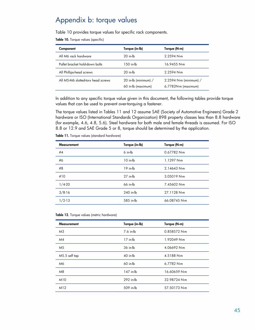
45
Appendix b: torque values Table 10 provides torque values for specific rack components.
Table 10. Torque values (specific)
Component Torque (in-lb) Torque (N-m)
All M6 rack hardware 20 in-lb 2.2594 N-m
Pallet bracket hold-down bolts 150 in-lb 16.9455 N-m
All Phillips-head screws 20 in-lb 2.2594 N-m
All M5-M6 slotted-torx head screws 20 in-lb (minimum) /
60 in-lb (maximum)
2.2594 N-m (minimum) /
6.7782N-m (maximum)
In addition to any specific torque value given in this document, the following tables provide torque values that can be used to prevent over-torquing a fastener.
The torque values listed in Tables 11 and 12 assume SAE (Society of Automotive Engineers) Grade 2 hardware or ISO (International Standards Organization) 898 property classes less than 8.8 hardware (for example, 4.6, 4.8, 5.6). Steel hardware for both male and female threads is assumed. For ISO 8.8 or 12.9 and SAE Grade 5 or 8, torque should be determined by the application.
Table 11. Torque values (standard hardware)
Measurement Torque (in-lb) Torque (N-m)
#4 6 in-lb 0.67782 N-m
#6 10 in-lb 1.1297 N-m
#8 19 in-lb 2.14643 N-m
#10 27 in-lb 3.05019 N-m
1/4-20 66 in-lb 7.45602 N-m
3/8-16 240 in-lb 27.1128 N-m
1/2-13 585 in-lb 66.08745 N-m
Table 12. Torque values (metric hardware)
Measurement Torque (in-lb) Torque (N-m)
M3 7.6 in-lb 0.858572 N-m
M4 17 in-lb 1.92049 N-m
M5 36 in-lb 4.06692 N-m
M5.5 self tap 40 in-lb 4.5188 N-m
M6 60 in-lb 6.7782 N-m
M8 147 in-lb 16.60659 N-m
M10 292 in-lb 32.98724 N-m
M12 509 in-lb 57.50173 N-m

46
For more information
HP contact phone numbers are as follows:
• Buy Direct: Small & Medium Business: 800-888-9909 • Buy Direct Large Enterprise Business: 800-282-6672 • Post-sales: 1-800-652-6672
For more information on ProLiant servers, visit www.hp.com/servers/proliant.
For more information on HP 10000 Series Racks and options, visit www.hp.com/products/racks.
Learn more about optional rack features at www.hp.com/products/rackoptions.
Learn more about ProLiant server power protection and management at www.hp.com/products/ups.
© 2003, 2006, 2007 Hewlett-Packard Development Company, L.P. The information contained herein is subject to change without notice. The only warranties for HP products and services are set forth in the express warranty statements accompanying such products and services. Nothing herein should be construed as constituting an additional warranty. HP shall not be liable for technical or editorial errors or omissions contained herein.
TC060304BP, 2/2007
Printed in the US