bending andtorsionalreconfiguration ofchiralrodsunder wind...
TRANSCRIPT

Bending and Torsional Reconfiguration of Chiral Rods Under Wind
and Gravity
Masoud Hassania,∗ , Simon Molgat Laurina, Njuki W. Mureithia, Frederick P. Gosselina,∗
aDepartment of Mechanical Engineering, Ecole Polytechnique de MontrealC.P. 6079, Succ. Centre-ville, Montreal, Quebec, Canada H3C 3A7
Abstract
We seek to understand the effect of chirality on the reconfiguration and the self-buckling strength of
chiral plants subjected to wind and gravity by experimental and theoretical modeling of their large
deformation. Chiral rod and ribbon specimens are made of polyurethane foam reinforced with nylon
fibers and ABS plastic. Wind tunnel tests are performed to evaluate the effect of chirality on flow-
induced reconfiguration. A theoretical model is developed by coupling the Kirchhoff rod theory with
a semi-empirical formulation for aerodynamic loading evaluation. A range of geometrical, material
and flow parameters are studied in the experimental and theoretical model. It is shown that for rods,
chirality decreases the maximum root bending moment. For ribbons, chirality leads to a trade-off
with higher self-buckling strength but also higher root bending moment. Moreover, chirality reduces
the effect of the loading direction on deformation. Chirality plays an important structural role in the
interaction of slender structures with fluid flow and gravity loading.
Key words: Reconfiguration, Drag reduction, Torsion, Large deformation, Buckling, Root bending
moment, Kirchhoff rod.
1. Introduction
In general, plants and vegetation are flexible and are prone to significant deformation under
fluid loading, their own weight or precipitation load. The deformation of plants which usually
leads to a drag reduction, is termed reconfiguration [1]. The reconfiguration of plants has been
studied fundamentally by modeling them as simple mechanical structures such as bending beams
[2], fibers [3, 4] and plates [5, 6, 7]. Although these aforementioned models can simplify the two-
dimensional deformation of plants, they are not representative for all forms of reconfiguration. For
∗Corresponding authorEmail addresses: [email protected] (Frederick P. Gosselin)
Preprint submitted to Extreme Mechanics Letters February 5, 2017
instance, many plants grow with a chiral morphology which cannot be modeled by a simple bend-
ing beam.
Chirality can be found in many biological and artificial structures, from DNA and several types
of plants [8] to some polymers [9] and nano-materials [10, 11]. Many aquatic plants such as cattail,
threeleaf arrowhead, sweet flag, bur-reed [8] and terrestrial plants such as daffodil and pancratium
possess chiral leaves or stems [12]. In general, the evolutionary aspect of chirality in biological
structures has been discussed in many studies. For instance, it is of great interest to know whether
the chiral morphology of DNA was a requirement or an outcome of evolution [13]. Moreover, it has
been claimed in some studies that erect plants with chiral morphology are less vulnerable to dis-
tributed transverse loading and Euler buckling [8, 12, 14]. The latter may be evidence of adaptation
of this type of plants to their environment through a long evolution process.
Chiral structures have been studied mathematically using different theories such as Timoshenko
pre-twisted beams [8, 12], Kirchhoff rods [11, 15, 16], and Cosserat rods [17]. However, the mathe-
matical study of the large deformation of chiral plants bending and twisting in flow is missing from
the literature. Therefore, the goal of this work is to study the reconfiguration mechanisms of chiral
plants subjected to wind and gravity through a combination of chiral rod simulations and wind tun-
nel experiments. We seek to understand the effect of chirality on the ability of plants to withstand
the fluid loading and their own weight.
2. Methodology
2.1. Experimental Procedure and Materials
The tests on flexible specimens with chiral morphology were performed in a wind tunnel located
at Ecole Nationale d’Aerotechnique (Saint-Hubert, QC, Canada). The wind tunnel has a square test
section of 60 × 60 cm2 and can produce a maximum air speed of 38 ms−1. As detailed in Ref. [18], a
six-axis force transducer (ATI GAMMA, ATI Industrial Automation, Apex, North Carolina) was used
in the present experiments to measures the aerodynamic forces and moments in three orthogonal
directions. It can measure transverse forces, axial forces and moments up to 32N, 100N and 2.5Nm,
respectively. The resolution of the force transducer is 6.25×10⁻³ N and 12.5×10⁻³ N for the transverse
and axial loading and 0.5 × 10⁻³ Nm for moments. The force transducer was fixed to the top of the
wind tunnel test section. The specimens were clamped to the force balance at one end using a mast
to subtract the effect of boundary layer on the tunnel wall from the measurements. In each test, the
2

root incidence angle of a specimen was fixed within a range of ψ0 = 0 to 90 or 90 to 180, then
the flow velocity was increased from 3.5ms−1 to more than 30ms−1 depending on the stability of the
specimen. A Labview code was used to acquire and save aerodynamic forces and moments.
Two types of flexible specimens were used in the experiments: circular rods and flat ribbons.
The circular rods are made using polyurethane foam and are internally reinforced with nylon fibers
as described in [18] and the supplementary file. The fibers are positioned along one diameter of a
cylindrical mold and twisted around its centerline. Foam is poured and and left to expand in the
closed mold, then cure over several hours. As a result, the rod is conferred with anisotropic bending
rigidity (EI)y/(EI)x < 1 and a natural twist (Fig 1a). To evaluate the uniformity of foam rods, a
specimen was cut to smaller pieces of equal size. Measuring the weight of pieces showed that the
density of the foam varies by approximately seven percent along the length of a rod, which is uni-
form enough for the purpose of this study. Moreover, the foam rigidity is significantly smaller than
that of fibers therefore the effect of this non-uniformity is minimized. To maintain the uniformity
of fibers inside the foam, they were kept apart with small spacers to ensure a uniform twist and a
constant distance between them. A circular section was used in order to simplify the fluid loading
evaluation in the theoretical model. The flat ribbons, on the other hand, have intrinsic directional
rigidity due to their greater-than-unity width to thickness ratio (Fig 1b). They are made of ABS plas-
tic and twisted along their length with a range of intrinsic twist angles τ0. Annealing at 100 C for
several hours was performed to make the twisted state of the rods their stress-free state (see the
supplementary file for more detail).
The anisotropic bending rigidity of the rods and the ribbons form a material frame (ex,ey,ez)
where ey is along the more rigid direction (Fig 1c and d) and ez is tangent to the centerline (Fig 1e).
For a chiral ribbon, fluid loading depends on the alignment of its sections with respect to the flow
direction i.e. the local angle of incidence ψ [18]. The directional rigidity gives rise to a three-
dimensional deformation in asymmetric bending. In the tests, the clamped end of each specimen
was rotated around its centerline to have different values of incidence angle at the clamped end ψ0.
Eleven specimens, as listed in Table 1, were made for a range of intrinsic twist angles τ0 varying from
0 to 720. The specimens named C are circular reinforced rods made of polyurethane foam and the
specimens named S are ribbons made of ABS plastic. Three-points bending tests were performed
with a universal testing frame to evaluate the bending rigidity of the rods and ribbons. The Young’s
modulus for all ribbon specimens is the same. For the circular rods, it is assumed that the Young’s
3

modulus of the foam part has a linear relation with the rod’s density. The maximum and minimum
bending rigidity for a circular rod with τ0 = 0 was measured and the rigidity of the other circular
rods was reconstructed based on the aforementioned assumption.
(a)
(b)
(c)
(d)
(e)
U
U
U
ex
ex
ex
ey
ey
ey
ez
eX
eX
eX
eY
eY
eY
eZ
ψ
ψ
Figure 1: a) Schematics of chiral rods with an intrinsic twist angle varying from 0 to 360
as well as a real rod specimen. b)Schematics of chiral ribbons with an intrinsic twist angle varying from 0
to 360 a well as a real twisted ribbon. c) Section
of a chiral rod and d) section of a chiral ribbon both with an incidence angle of ψ. e) Schematic of a chiral ribbon deformedin the flow with a moving material frame attached to its centerline.
2.2. Theoretical Model
The three-dimensional reconfiguration of chiral structures is modeled theoretically using the
Kirchhoff theory of rods. In the model, a rod is represented by a deforming three-dimensional and
inextensible curve with the assumption of small strains [19]. It is also assumed that each cross
section of the rod remains planar and normal to the centerline. The rod is attached to a fixed coor-
dinate system (eX ,eY ,eZ) from one end and moving material frames (ex,ey,ex) are attached to its
centerline (Fig 1e). Bending moments and the twisting moments are proportional to the curvatures,
(κx , κy) and the twist (τ), respectively:
Mx = (EI)xκx , My = (EI)yκy , Mz = GJτ , (1)
4
where (EI)y and (EI)x are the bending rigidities and GJ is the torsional rigidity. In this model, the
natural twist and curvature of a rod is represented by κx,0, κy,0 and τ0. As detailed in Ref. [18], the
equilibrium Kirchhoff equations are:
dNx
ds= Nyτ − Tκy −Px −Wx , (2)
dNy
ds= Tκx −Nxτ −Py −Wy , (3)
dT
ds= Nxκy −Nyκx −Pz −Wz , (4)
(EI)xdκx
ds= (EI)y(κy − κy,0)τ −GJ(τ − τ0)κy +Ny , (5)
(EI)ydκx
ds= GJ(τ − τ0)κx − (EI)x(κx − κx,0)τ −Nx , (6)
GJdτ
ds= (EI)x(κx − κx,0)κy − (EI)y(κy − κy,0)κx , (7)
where Nx and Ny are shear forces and T is the internal tensile force. Moreover, P is the external
loading and W = mgL−1 is the weight per unit length in the Z-direction, both decomposed in the
three directions of the material frame. The material frame (ex,ey,ez) is related to the fixed frame
(eX ,eY ,eZ) through the direction cosine matrix [c]:
⎧⎪⎪⎪⎪⎪⎪⎪⎨⎪⎪⎪⎪⎪⎪⎪⎩
ex
ey
ez
⎫⎪⎪⎪⎪⎪⎪⎪⎬⎪⎪⎪⎪⎪⎪⎪⎭
=
⎡⎢⎢⎢⎢⎢⎢⎢⎢⎢⎣
c11 c12 c13
c21 c22 c23
c31 c32 c33
⎤⎥⎥⎥⎥⎥⎥⎥⎥⎥⎦
⎧⎪⎪⎪⎪⎪⎪⎪⎨⎪⎪⎪⎪⎪⎪⎪⎩
eX
eY
eZ
⎫⎪⎪⎪⎪⎪⎪⎪⎬⎪⎪⎪⎪⎪⎪⎪⎭
. (8)
The direction cosines represent the rotation of the material frame and they are the cosines of the
angles between a direction of the material frame and the directions of the fixed frame. The spatial
Table 1: Physical properties of tested specimens
Specimen L (cm) d (cm) t (cm) (EI)y(Nm2)
(EI)yGJ
(EI)y(EI)x
Weight (g) Twist τ0C1 26 1.9 - 0.0036 1.25 0.16 25 0
C2 26 1.9 - 0.0036 1.25 0.16 25 90
C3 26 1.9 - 0.0036 1.25 0.16 25 180
C4 26 1.9 - 0.0029 1.25 0.13 20 270
C5 26 1.9 - 0.0029 1.25 0.13 20 360
C6 26 1.9 - 0.0029 1.25 0.13 20 720
S1 40 2.5 0.12 0.010 0.675 0.0022 13 0
S2 40 2.5 0.12 0.010 0.675 0.0022 13 90
S3 40 2.5 0.12 0.010 0.675 0.0022 13 180
S4 40 2.5 0.12 0.010 0.675 0.0022 13 270
S5 40 2.5 0.12 0.010 0.675 0.0022 13 360
5

derivative of a direction of the material frame with respect to the arclength s is [20]:
dei
ds=Ω × ei , (9)
where ei is a direction of the material frame and Ω is the Darboux vector :
Ω = κxex + κyey + τez . (10)
Substituting Eq.(10) in Eq.(9) leads to a system of nine equations, six of which are independent. In
the model, the six independent spatial derivative equations are coupled with the Kirchhoff equa-
tions (Eq.(2) to Eq.(7)) to define the full state of the deformed rod.
A semi-empirical formulation of the aerodynamic force on a rod is also used to evaluate the
loading on the deformed specimens [18, 21]. In this method, the local lift and drag of a rod element
depends only on the element’s orientation and the normal component of the flow velocity to the
centerline at the element. The flow velocity is taken to be in the X-direction:
U = UeX = Uzez +Unen , (11)
where U is the magnitude of the flow velocity and en is the direction normal to the centerline in the
XZ-plane. The local angle α between the centerline of the rod and the flow velocity direction is:
cosα = ez.eX = c31 , sinα =√1 − c2
31. (12)
Therefore, the component of flow velocity normal to the centerline is:
Un = U√
1 − c231. (13)
The friction drag along the centerline produced by Uzez is not considerable therefore we neglect it
in the model. The drag normal to the centerline per unit length is in the direction of the normal
velocity:
D =1
2ρdCDUn
2en , (14)
6

where CD is the drag coefficient. Similarly, the normal lift force per unit of length is written as:
L =1
2ρdCLUn
2el , (15)
where CL is the lift coefficient and el is the direction of the normal lift force. The direction of the
normal drag en is parallel to the projection of eX on the xy-plane:
en =eX − (eX .ez)∣eX − (eX .ez)∣
=c11ex + c21ey√
1 − c231
, (16)
Similarly, the direction of the normal lift el is parallel to the projection of eY on the xy-plane:
el =eY − (eY .ez)∣eY − (eY .ez)∣
=c12ex + c22ey√
1 − c232
. (17)
By extending this approach, the normal lift and drag forces of a deformed ribbon element δs can
be evaluated locally by introducing the sectional drag and lift coefficients CD(s) and CL(s) which
depend on the local orientation of the rod. This is based on the assumption that the cross section
of rods and ribbons does not deform. To evaluate the sectional drag and lift coefficients for rib-
bons whether chiral or straight, wind tunnel measurements are performed on rigid straight metal-
lic strips with a similar geometry and the same sectional aspect ratio√(Ix/Iy) for a range of angles
of incidence ψ0. Consequently, the variation of CD and CL as a function of the angle of incidence
is obtained for a rectangular section. In addition, the variation of the sectional angle of incidence
for a deformed ribbon, as a function of the arc length s, is calculated in the mathematical model.
Therefore, CD and CL as a function of the arc length s can be evaluated. For a circular rod, CD(s)
is a constant and CL(s) is null. It is assumed that for Reynolds numbers within the range of 103 to
105, the drag and lift coefficients do not change with flow velocity.
The external loading P in Eq.(2) to Eq.(4) for a rod in fluid flow is the resultant of the drag and
lift forces. By decomposing the external loading in the directions of the material frame we have:
Px = D.ex + L.ex , (18)
Py = D.ey + L.ey , (19)
Pz = 0 . (20)
7

The angle between the x and y-components of the normal drag is the sectional angle of incidence.
Therefore, using Eq.(18) and Eq.(19)
ψ = arctan(−c21c11) . (21)
In the model we assume that the positive rotation is clockwise thus a negative sign is imposed in
Eq.(21).
2.2.1. Dimensionless Equations
Dimensionless Kirchhoff equations of a deforming rod are written using the Cauchy number:
CY =ρU2L3d
2(EI)y. (22)
The Cauchy Number is the ratio of the fluid force to the minimum bending rigidity of the flexi-
ble body [6, 22, 23]. The following dimensionless parameters are also introduced in the Kirchhoff
equations [18]:
s = s/L κx = κxL κy = κyL τ = τL ,
Nx =NxL
2
(EI)yNy =
NyL2
(EI)yT =
TL2
(EI)yW = mgL
2
(EI)y.
By introducing the aforementioned dimensionless parameters in Eq.(2) to Eq.(7), dimensionless
Kirchhoff equations are written as follows:
dNx
ds= Ny τ − T κy − Px −Wx , (23)
dNy
ds= T κx − Nxτ − Py −Wy , (24)
dT
ds= Nxκy − Nyκx − Pz −Wz , (25)
dκx
ds= λ(κy − κy,0)τ − (
λ
η)(τ − τ0)κy + λNy , (26)
dκx
ds= (1
η)(τ − τ0)κx − (
1
λ)(κx − κx,0)τ − Nx , (27)
dτ
ds= (η
λ)(κx − κx,0)κy − η(κy − κy,0)κx , (28)
8

where the dimensionless external forces are
Px = CY CD(s)√(1 − c312)c11 +CY CL(s)
1 − c312
1 − c322c12 , (29)
Py = CY CD(s)√(1 − c312)c21 +CY CL(s)
1 − c312
1 − c322c22 . (30)
Dimensionless parameters λ and η are the bending rigidity ratio and the twist-to-bend ratio, re-
spectively [18]:
λ =(EI)y(EI)x
, (31)
η =(EI)yGJ
. (32)
Since the dimensionless weight of the rod is in the Z-direction of the fixed frame, it is decomposed
in the three directions of the material frame as:
Wx =W .c31 , (33)
Wy =W .c32 , (34)
Wz =W .c33 . (35)
The system of equations including Eq.(23) to Eq.(28) coupled with Eq.(9) is solved using MATLAB
as a boundary value problem using the bvp4c solver. As explained in [18], a continuation approach
is used to solve the system of equations. In the method, an initial guess for all twelve variables is
considered. The solution is then evaluated step by step for an increasing Cauchy number. This
approach is continued up to a higher limit of Cauchy number i.e. 1000. However, to study the
cases including a static instability such as buckling, the governing equations are solved using AUTO
[24]. This software package solves problems which can include bifurcations. In the software, a
continuation parameter is considered and the governing equations are solved for a range of that
parameter. For this buckling problem, the dimensionless weightW is the continuation parameter.
A cross-comparison has been done for cases without bifurcation between the MATLAB code and
the AUTO solver which show identical results to seven significant figures [18].
9
τ0 (deg)
1
1.05
1.1
1.15
1.2
1.25
0
0 0120 1506030 90 90180 180 360270 450 540 630 720
Asymp. 1.12
Asymp. 1.21
Asymp. 1.29
(a) (b)
Lr
λ = 0.5λ = 0.16λ = 0.0022
τ0 = 0
τ0 = 360
τ0 = 720M
ax
de
fle
cti
on
(m)
0.04
0.08
0.12
0.16
ψ0 (deg)
Figure 2: a) Static bending test for chiral circular rods. The rods are fixed horizontally from one end and their maximumvertical deflection is plotted vs. the angle of incidence at the fixed end. Markers represent the experimental results. b) Theeffect of chirality and the bending rigidity ratio of rods on their critical buckling length.
3. Results and Discussion
3.1. Mathematical Model Verification
A comparison has been performed in Ref. [18] on the three-dimensional deformed shape of
non-chiral rods, obtained from wind tunnel tests and the present mathematical model. Herein, only
the validation of the chirality component in the mathematical model is investigated. To validate
the mathematical model, the numerical and experimental results for the deformation of circular
chiral rods with different τ0 are presented in Fig. 2a. In the test, the rods were clamped from one
end horizontally, and deforming under their own weight. Each specimen was rotated around its
centerline to have different values of incidence angle at the clamped end ψ0. In the figure, the tip
vertical deflection is plotted as a function of the incidence angle for three different intrinsic twist
angles. Markers represent the measured values and curves represent the mathematical prediction.
Results show that the maximum vertical deflection and consequently the effective bending rigidity
varies with the incidence angle ψ0. Moreover, by increasing the intrinsic twist angle, the deflection
of the rods becomes less dependent upon the direction of loading. The mathematical model shows
good agreement with the experimental results. Another verification is carried out by comparing the
measured drag and lift coefficients of a rigid twisted rod (τ0 = 90) with the mathematical model
which is provided in the supplementary file.
10
3.2. Buckling
It has been noted that chirality is beneficial to plants since it increases their strength against
buckling under their own weight or that of their head organ [8, 12]. We study the buckling of chiral
ribbons and rods under their own weight which are similar to upright slender plants without a head
organ such as a cattail leaf. Figure 2b illustrates the effect of chirality on the relative critical length
of buckling Lr =Lcr/Lcr,0 where Lcr,0 is the critical length of a non-chiral rod or ribbon (τ0 = 0)
buckling in the plane of least resistance (ψ0 = 0). It should be mentioned that according to our
mathematical modeling and also the Euler buckling theory, Lcr,0 ≈3
√7.837(EI)y/γ for a self weight
buckling case where γ is the weight per unit length. In the figure, Lr is plotted for several bending
rigidity ratios and for a range of intrinsic twist angle from 0 to 720. Each curve corresponds to
a value of the bending rigidity ratio while the other structural parameters are kept constant. It is
shown that increasing the intrinsic twist angle increases the critical buckling length meaning that
the buckling strength is increased. Moreover, decreasing the bending rigidity ratio or equivalently
increasing the sectional aspect ratio, increases the influence of chirality on the critical buckling
length. This means that chirality is more effective for ribbons with a small λ than rods with a circular
section and large λ. In addition, the twist-to-bend ratio η does not affect the critical buckling length.
3.3. Drag and Lift Coefficients
As mentioned before, for the mathematical model it is necessary to evaluate the sectional drag
and lift coefficients of the rods as a function of the sectional angle of incidence. For circular rods,
the drag coefficient of an equivalent rigid rod is measured as CD = 0.95 which is used as the sec-
tional drag coefficient. For the ribbons, the drag and lift coefficients of an equivalent flat metallic
strip were measured for a range of incidence angles. To simplify the model, the average of the drag
and lift measurements for Re = 10000 and 20000 were fitted using trigonometric functions (see the
supplementary file):
CD(ψ) = 1.37 ∣cos(ψ)∣ + 0.05 , (36)
CL(ψ) = 0.80 sin(2ψ) . (37)
The flat metallic strip possessed the same dimensions as the flexible ribbons (400×25.4mm). More-
over, the measured pitching moment was found to be very small with respect to the torsional rigidity
of ribbons therefore it was neglected in the mathematical model.
11

3.4. Drag of Flexible Specimens
Herein, the wind tunnel results represent the time-averaged values of fluctuating loads mea-
sured over 30 seconds. The time-averaged values exhibit a standard deviation of less than 10 per-
cent, or else are deemed unacceptable and are discarded. At high velocities, the rods and the rib-
bons underwent large amplitude vibrations possibly due to turbulence buffeting, although some
flutter or galloping phenomena cannot be ruled out. For the lowest flow velocity in the experiments,
the vortex shedding frequency is estimated to 40 Hz for a Strouhal number of 0.2. This frequency
is largely beyond the fundamental frequency of the tested ribbons and circular rods which is of the
order of 2 Hz [18]. In the results presented here, only the static deformations of the rods and ribbons
are considered.
In reality, plants can be subjected to wind loading from any direction. The present work shows
that the drag on a specimen is highly dependent on the incidence angle. Figure 3a and Fig. 3b show
rose plots of drag force on chiral circular rods atU = 13ms−1 and ribbons atU = 15ms−1, respectively.
On the rose plots, the radial distance of points indicates the drag loading magnitude as a function of
the angle of incidence, i.e. the loading direction. In the figures, each curve represents a simulation
for a fixed value of the intrinsic twist angle while symbols represent its equivalent experimental
data. The aforementioned flow velocities were selected for large deformations with a maximum
number of valid wind tunnel tests. A range of 90 for ψ0 was tested in the wind tunnel. However,
depending on the initial alignment and the handedness of chiral specimens, either the range of
ψ0 = 0 to 90 or ψ0 = 90
to 180 was measured. As seen, the drag force strongly varies with the wind
direction for a non-chiral rod and ribbon. As the intrinsic twist angle increases, both plots approach
a perfect circle meaning that the drag becomes less direction dependent. It should be noted that
some of the experimental data are missing in the plots because they were not acceptable due to a
standard deviation larger than 10 percent.
To better understand the effect of chirality, for each intrinsic twist angle, we vary the incidence
angle to maximize and minimize drag. Figure 3c and Fig. 3d show the mathematical prediction of
these extremums for chiral circular rods and ribbons for a range of the intrinsic twist angle τ0 from
0 to 720. In these figures, the relative drag of rigid circular rods as well as the maximum and min-
imum drag of equivalent rigid ribbons are provided for reference. In the mathematical model, the
relative drag of chiral rods and ribbons with a specific chiral angle τ0, is evaluated for a range of ψ0
from 0 to 360. The maximum and minimum relative drag can be found at any angle in this range
12

depending on τ0. The relative drag force is calculated as Dr = D/D0 where D0 is the drag of a rod
with τ0 = 0 and ψ0 = 0
. The markers represent the experimental drag data regardless of the inci-
dence angle. The relative drag force of a non-chiral rod is maximum at ψ0 = 90 and minimum at
ψ0 = 0. On the other hand, the relative drag force of a non-chiral ribbon is maximum atψ0 ≈ 45
and
the minimum at ψ0 = 90. The reason is that the projected area of a circular rod does not change
with ψ0 but the projected area of a non-chiral ribbon is minimum at ψ0 = 90 and maximum at
ψ0 = 0. This is valid only for non-chiral rods and ribbons and it is not necessarily applied to chiral
ones. In Fig. 3c, the flow velocity is U = 13 ms−1 which is equivalent to CY = 10 where reconfigura-
tion is important. For the mathematical model, the average mechanical properties of the circular
rods in Table 1 were used. Moreover, a constant CD = 0.95 was considered. As seen, the maximum
relative drag decreases and the minimum relative drag increases. This means that the difference be-
tween the maximum and the minimum drag decreases indicating that the drag becomes direction
independent for high intrinsic twist angles. This is similar to the static bending results presented in
Fig. 2a which shows that the chirality makes the deformation of a rod less dependent on the loading
direction. It can also be found in Fig. 3c that chirality is beneficial for circular rods since it decreases
the fluid loading. Higher drag forces usually lead to higher stresses therefore chirality should be
helpful for plants with circular or semi-circular sections in reducing the probability of structural
failure.
Fig. 3d presents the relative drag force on chiral ribbons for U = 15 ms−1 or CY = 20. It is seen
that the minimum and the maximum relative drag increase up to a value of τ0 of 90 and 180,
respectively. Beyond 180, the maximum drag decreases. Similarly to Fig. 3c, the range between
the maximum and the minimum drag values decreases with increasing intrinsic twist angle. In
addition, the drag of rigid ribbons also becomes less directional and approaches an asymptotic
value. Similarly, it was reported in [25] that the drag coefficient of a rigid chiral ribbon approaches
a constant value for very high twist angles. The maximum and minimum drag of rigid ribbons
exhibit a periodic variation with chirality. This periodic variation is less pronounced for flexible
ribbons. The reason is that in general, the drag of flexible ribbons is less than rigid ones therefore
the variation amplitude of their maximum and minimum drag is also smaller. Moreover, flexible
ribbons deform and become aligned with the flow. This reduces the effect of chirality on their drag.
This trend is not present for circular chiral rods because it is related to the complex aerodynamic
loading on chiral ribbons. For a chiral cylinder, the aerodynamic loading is governed by a single
13

constant drag coefficient regardless of the intrinsic twist angle. In this case, the structural effect
of chirality governs the drag scaling. On the other hand, a chiral ribbon is affected by both the
structural and the aerodynamic aspects of the chiral morphology. The competition between these
two aspects of chirality leads to a more complex response in chiral ribbons.
(a) (b)
(c) (d)
τ0 (deg) τ0 (deg)
0
0
0
0
0 00 0
60 60
30 30
90 90
90 90
180 180
180 180
120 120
150 150210 210
240 240
300 300
330 330
360 360
270 270
270 270450 450540 540630 630720 720
0.8
0.8
0.4
0.4
1.2
1.2
0.3
0.30.1
0.2
0.5
0.6
0.9
1.6
1.6
2.4
3.2
D/D
0
D/D
0
τ0 = 0 τ0 = 180
τ0 = 360 τ0 = 720
Flexible-maximum dragFlexible-minimum dragRigid-maximum dragRigid-minimum dragExperimental data
Figure 3: Rose plot of drag as a function of the intrinsic twist angle, τ0 and the incidence angle, ψ for a) chiral circular rodswith U = 13 ms
−1 and b) chiral ribbons with U = 15 ms−1. c) Maximum and minimum relative drag of chiral circular rods at
U = 13 ms−1 and d) chiral ribbons at U = 15 ms
−1 among a range of incidence angles. Markers represent the experimentaldata and lines show the mathematical prediction. The maximum and minimum drag of equivalent rigid rods and ribbonsare also provided for reference.
3.5. Curvature and Bending Moment
Chirality induces a non-uniform distribution of curvature along the length of the rod or ribbon.
This is shown in Fig. 4 for ribbons using the mathematical model. The results are qualitatively
14
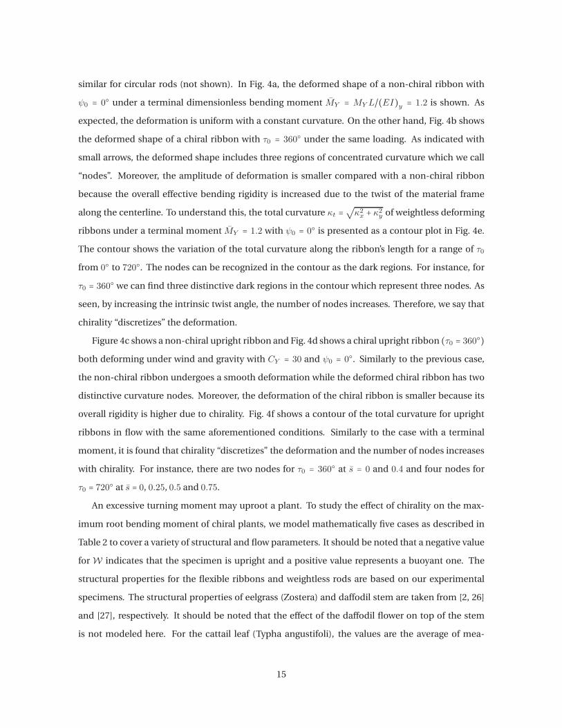
similar for circular rods (not shown). In Fig. 4a, the deformed shape of a non-chiral ribbon with
ψ0 = 0 under a terminal dimensionless bending moment MY = MY L/(EI)y = 1.2 is shown. As
expected, the deformation is uniform with a constant curvature. On the other hand, Fig. 4b shows
the deformed shape of a chiral ribbon with τ0 = 360 under the same loading. As indicated with
small arrows, the deformed shape includes three regions of concentrated curvature which we call
“nodes”. Moreover, the amplitude of deformation is smaller compared with a non-chiral ribbon
because the overall effective bending rigidity is increased due to the twist of the material frame
along the centerline. To understand this, the total curvature κt =√κ2x + κ
2y of weightless deforming
ribbons under a terminal moment MY = 1.2 with ψ0 = 0 is presented as a contour plot in Fig. 4e.
The contour shows the variation of the total curvature along the ribbon’s length for a range of τ0
from 0 to 720. The nodes can be recognized in the contour as the dark regions. For instance, for
τ0 = 360 we can find three distinctive dark regions in the contour which represent three nodes. As
seen, by increasing the intrinsic twist angle, the number of nodes increases. Therefore, we say that
chirality “discretizes” the deformation.
Figure 4c shows a non-chiral upright ribbon and Fig. 4d shows a chiral upright ribbon (τ0 = 360)
both deforming under wind and gravity with CY = 30 and ψ0 = 0. Similarly to the previous case,
the non-chiral ribbon undergoes a smooth deformation while the deformed chiral ribbon has two
distinctive curvature nodes. Moreover, the deformation of the chiral ribbon is smaller because its
overall rigidity is higher due to chirality. Fig. 4f shows a contour of the total curvature for upright
ribbons in flow with the same aforementioned conditions. Similarly to the case with a terminal
moment, it is found that chirality “discretizes” the deformation and the number of nodes increases
with chirality. For instance, there are two nodes for τ0 = 360 at s = 0 and 0.4 and four nodes for
τ0 = 720 at s = 0, 0.25, 0.5 and 0.75.
An excessive turning moment may uproot a plant. To study the effect of chirality on the max-
imum root bending moment of chiral plants, we model mathematically five cases as described in
Table 2 to cover a variety of structural and flow parameters. It should be noted that a negative value
for W indicates that the specimen is upright and a positive value represents a buoyant one. The
structural properties for the flexible ribbons and weightless rods are based on our experimental
specimens. The structural properties of eelgrass (Zostera) and daffodil stem are taken from [2, 26]
and [27], respectively. It should be noted that the effect of the daffodil flower on top of the stem
is not modeled here. For the cattail leaf (Typha angustifoli), the values are the average of mea-
15

0 000 0
0
1
1 1
2
2
3
4
4
5
6
6
7
8
10
12
14
0.2 0.20.4 0.40.6 0.60.8 0.8
9090
180180
360360
270270
450450
540540
630630
720720
(a) (b) (c) (d)
(e) (f)
s s
τ0 τ0
Figure 4: Theoretical evaluation of the deformed shape of weightless ribbons under a terminal moment with a)τ0 = 0 and
b)τ0 = 360. Deformed shape of upright ribbons under the wind loading with c)τ0 = 0
and d)τ0 = 360. Contour of the
total curvature κt for e) weightless chiral ribbons under a terminal moment and f) upright ribbons in the flow. The terminalmoment is MY = 1.2, the Cauchy number is CY = 30 and ψ0 is null for all cases. Small arrows show the curvature nodes onthe deformed ribbons.
surements which we did on several leaves. Twelve mature leaves were collected from the Voyageur
Provincial Park (ON, Canada) in August, 2016. Three-points bending tests were done on segments
of the leaves to evaluate their bending rigidity, one day after being collected. It was found that the
bending rigidity of a cattail leaf decreases significantly from root to tip mainly due to the reduction
of its thickness. Therefore, the average of the bending rigidity, width and thickness of multiple leaf
segments was used in the mathematical model. Based on present experiments on cattail leaves,
the bending rigidity varies from 0.03 × 10⁻³ Nm2 for the tip section to 3.9 × 10⁻³ Nm2 for the root
section. This shows two orders of magnitude of change in the bending rigidity from tip to root. The
average bending rigidity for the cattail leaves is 0.87 × 10⁻³ Nm2. Moreover, λ varies for the tested
cattail leaves from 0.0025 to 0.1 with an average of 0.032 (see the supplementary file for more de-
Table 2: Physical properties of study cases
Case Section L (cm) d (mm) t (mm) (EI)y(Nm2) η λ W CY
Flexible Ribbon Rectangular 40 25.4 1.2 0.01 0.675 0.0022 −1.93 30
Ealgrass Rectangular 40 8 0.35 2.8e − 5 1 0.0019 20 30
Cattail leaf Rectangular 65 7.6 1.26 0.87e − 3 1 0.032 −6.6 30
Weightless Rod Circular 26 19 - 0.0033 1.25 0.16 0 30
Daffodil Stem Semi-circular 27 8.5 - 0.012 13.3 0.5 −0.92 30
16

tail). Using the model, the maximum value of the dimensionless bending moment Mmax computed
over a range of incidence angles from 0 to 180 is plotted for the aforementioned cases in Fig. 5,
where M = L√M2
x +M2y /(EI)y. The plots illustrate the variation of Mmax at root as a function of
the intrinsic twist angle τ0. For the daffodil stem, an aerodynamic model similar to a circular rod is
used although in reality, the cross section is semi-circular or elliptic. Moreover, the bending rigidity
ratio λ for the daffodil stem is calculated as the ratio of the second moment of area around the two
sectional axes of symmetry (Iy/Ix). As seen, the variation of Mmax is different between the ribbons
with rectangular sections and rods with circular or semi-circular sections. For the circular or semi-
circular cases, Mmax at root decreases with increasing τ0 and approaches a constant value for very
high intrinsic twist angles. However, for the cases with a ribbon-like structure, Mmax increases up
to a certain value of τ0 between 120 and 150; beyond that, it decreases and approaches a constant
value. The mathematical model showed that for cattail leaves in air flow, Mmax is not significantly
sensitive to the variation of λ and the bending rigidity. Moreover, the peak value of Mmax is found
at 150 for all the study cases. At first glance, the figure suggests that an untwisted structure is better
for plants to reduce the root bending moment. However, as we understood from Fig. 2b, chirality
increases the buckling strength of upright ribbons which reduces the chance of structural failure.
Therefore, chirality brings a trade-off for upright plants with increased buckling strength but also
higher root bending moment. For instance, cattail leaves are chiral and according to our measure-
ments, their average intrinsic twist angle is 380 ± 110. The shaded area in Fig. 5 represents the
distribution of twist angles of the cattail specimens which we have collected. It should be noted
that the intrinsic twist angle of plants may vary with environmental parameters.
The results show that eelgrass is subjected to a larger root bending moment with respect to an
upright ribbon and a cattail leaf. The reason is that the buoyancy effect decreases the deformation
magnitude which leads to a larger drag as suggested by [2]. A larger drag on the plant’s body leads to
a larger root moment. In comparison, an upright ribbon and a cattail leaf are subjected to a smaller
root moment since their weight contributes to the deformation and drag reduction. On the other
hand, the reconfiguration of the daffodil stem is highly affected with its large η. This means that the
daffodil stem easily reorients to its less rigid direction which leads to a large deformation. The large
deformation of the daffodil then reduces the drag and the root moment. However, as seen in Fig. 5,
a weightless rod with a smaller η than the daffodil stem, has a larger root bending moment. This
is specifically interesting since it is known that many plants twist more easily than they bend [28],
17

which shows that low torsional rigidity is beneficial for plants to reduce the risk of uprooting.
According to Eq.(1), Mmax is created at the root due to the contribution of the curvatures in the
x and y-directions. Although κx is usually smaller than κy, its contribution to the bending moment
is usually more important due to the higher bending rigidity. This means that uprooting happens
because of an excessive bending moment created in the stiffer direction of the plant. Finally, the
difference in behavior between structures with rectangular sections and those with circular or semi-
circular sections comes from the different aerodynamic loadings on these structures.
τ0 (deg)
00
2
4
6
8
10
12
3
0
1
2
90 180 360270 450 540 630 720
Upright ribbon
Eelgrass, ribbon
Cattail leaf, ribbon
Daffodil stem, rod
Weightless rod
Mmax
Figure 5: Maximum dimensionless bending moment at root of five study cases at CY = 30. Plots are predicted using themathematical model. The shaded area represent the range of the most probable intrinsic twist angle of the cattail specimenscollected for this study. The small histogram plot shows the distribution of the collected specimens in terms of the intrinsictwist angle.
4. Concluding Remarks
The reconfiguration and buckling of chiral plants was studied using flexible rods and ribbons
with a chiral morphology. Wind tunnel experiments were conducted using circular rods with inter-
nal reinforcement as well as chiral ribbons. For the theoretical analysis, a Kirchhoff rod model was
coupled with a semi-empirical drag and lift formulation. The theoretical model provides a general
framework to study the large deformation of rods and ribbons as well as slender wings in flow. It was
shown that chirality increases the critical buckling length and consequently the buckling strength
of upright slender structures under their own weight. Chirality was found to render the rods and
ribbons less dependent on the direction of external loading such as gravity or wind. Moreover, chi-
ral rods and ribbons show a non-smooth deformation with one or more nodes in their deformed
shape due to their geometrical twist. Thus chirality can be said to “discretize” the deformation.
18
The theoretical model predicts that for circular rods, chirality decreases the root bending mo-
ment. On the contrary, the root bending moment of chiral ribbons is higher than a straight ribbon,
especially at intermediate angles of chirality around τ0 ≈ 150. Despite this, many upright plants
show a chiral morphology possibly due to its aforementioned benefits including higher buckling
strength and weaker dependency on the loading direction. Our measurements on chiral cattail
leaves showed that the distribution of their inherent twist angle bypasses the intermediate chiral
angles and is centered around a large chiral angle. However, it is of interest to perform measure-
ments on more chiral species which grow upright, to verify their angle of chirality. It is also recom-
mended to account for the variation of the sectional area and bending rigidity along the length in
the mathematical model to represent real plant organs such as leaves and stems. Moreover, further
experimental and theoretical investigations should be done to study the effect of chirality on the
dynamic stability of chiral plants against flutter and vortex-induced vibration.
Acknowledgment
The financial support of the Natural Sciences and Engineering Research Council of Canada is
acknowledged.
19

References
[1] S. Vogel, Drag and reconfiguration of broad leaves in high winds, Journal of Experimental
Botany 40 (1989) 8.
[2] M. Luhar, H. M. Nepf, Flow-induced reconfiguration of buoyant and flexible aquatic vegeta-
tion, Limnology and Oceanography 56 (2011) 2003–2017.
[3] S. Alben, M. Shelley, J. Zhang, Drag reduction through self-similar bending of a flexible body,
Nature 420 (2002) 479–481.
[4] S. Alben, M. Shelley, J. Zhang, How flexibility induces streamlining in a two-dimensional flow,
Physics of Fluids 16 (2004) 1694.
[5] F. P. Gosselin, E. de Langre, B. A. Machado-Almeida, Drag reduction of flexible plates by recon-
figuration, Journal of Fluid Mechanics 650 (2010) 319.
[6] F. P. Gosselin, E. de Langre, Drag reduction by reconfiguration of a poroelastic system, Journal
of Fluids and Structures 27 (2011) 1111–1123.
[7] L. Schouveiler, A. Boudaoud, The rolling up of sheets in a steady flow, Journal of Fluid Me-
chanics 563 (2006) 71.
[8] Z.-L. Zhao, H.-P. Zhao, B.-W. Li, B.-D. Nie, X.-Q. Feng, H. Gao, Biomechanical tactics of chiral
growth in emergent aquatic macrophytes, Scientific Reports 5 (2015) 12610.
[9] H.-M. Ye, J.-S. Wang, S. Tang, J. Xu, X.-Q. Feng, B.-H. Guo, X.-M. Xie, J.-J. Zhou, L. Li, Q. Wu,
G.-Q. Chen, Surface Stress Effects on the Bending Direction and Twisting Chirality of Lamellar
Crystals of Chiral Polymer, Macromolecules 43 (2010) 5762–5770.
[10] X. Chen, S. Yang, S. Motojima, M. Ichihara, Morphology and microstructure of twisting nano-
ribbons prepared using sputter-coated Fe-base alloy catalysts on glass substrates, Materials
Letters 59 (2005) 854–858.
[11] Z.-L. Zhao, H.-P. Zhao, J.-S. Wang, Z. Zhang, X.-Q. Feng, Mechanical properties of carbon nan-
otube ropes with hierarchical helical structures, Journal of the Mechanics and Physics of Solids
71 (2014) 64–83.
20
[12] K. Schulgasser, A. Witztum, Spiralling upward, Journal of theoretical biology 230 (2004) 275–
280.
[13] J. I. Lunine, J. Beauchamp, M. A. Smith, E. Nikolaev, The Abiotic Generation of Homochirality
on Saturns Moon Titan, in: Advances in BioChirality, volume 257, 1999.
[14] U. Rowlatt, H. Morshead, Architecture of the leaf of the greater reed mace, typha latifolia l.,
Botanical journal of the Linnean Society 110 (1992) 161–170.
[15] A. Goriely, P. Shipman, Dynamics of helical strips, Physical Review E 61 (2000) 4508.
[16] J.-S. Wang, H.-M. Ye, Q.-H. Qin, J. Xu, X.-Q. Feng, Anisotropic surface effects on the formation
of chiral morphologies of nanomaterials, Proceedings of the Royal Society A: Mathematical,
Physical and Engineering Sciences 468 (2012) 609–633.
[17] J.-S. Wang, Y.-H. Cui, T. Shimada, H.-P. Wu, T. Kitamura, Unusual winding of helices under
tension, Applied Physics Letters 105 (2014) 043702.
[18] M. Hassani, N. W. Mureithi, F. P. Gosselin, Large coupled bending and torsional deformation
of an elastic rod subjected to fluid flow, Journal of Fluids and Structures 62 (2016) 367–383.
[19] E. H. Dill, Kirchhoff’s theory of rods, Archive for History of Exact Sciences 44 (1992) 1–23.
[20] B. Audoly, Y. Pomeau, Elasticity and geometry: from hair curls to the non-linear response of
shells, Oxford University Press Oxford, 2010.
[21] G. Taylor, Analysis of the swimming of long and narrow animals, Proceedings of the Royal
Society A: Mathematical, Physical and Engineering Sciences 214 (1952) 158–183.
[22] S. K. Chakrabarti, The theory and practice of hydrodynamics and vibration, volume 20, World
scientific, 2002.
[23] E. de Langre, Effects of wind on plants, Annual Review of Fluid Mechanics 40 (2008) 141–168.
[24] E. Doedel, J. P. Kernevez, AUTO, software for continuation and bifurcation problems in ordi-
nary differential equations, California Institute of Technology, 1986.
[25] B. Cucuel, Mise en evidence des parametres influant sur les forces fluides et etablissement de
modeles empiriques de la trainee dobjets a geometrie variable, Master’s thesis, Ecole Polytech-
nique de Montreal, 2016.
21
[26] M. A. Abdelrhman, Modeling coupling between eelgrass Zostera marina and water flow, Ma-
rine Ecology Progress Series 338 (2007) 81–96.
[27] S. Etnier, S. Vogel, Reorientation of daffodil (narcissus: Amaryllidaceae) flowers inwind: drag
reduction andtorsional flexibility, American Journal of Botany 87 (2000) 29–32.
[28] S. Vogel, Twist-to-bend ratios and cross-sectional shapes of petioles and stems, Journal of
Experimental Botany 43 (1992) 1527–1532.
22