belding h&i o&m
TRANSCRIPT

7/27/2019 Belding H&I O&M
http://slidepdf.com/reader/full/belding-hi-om 1/21
7/27/2019 Belding H&I O&M
http://slidepdf.com/reader/full/belding-hi-om 2/21
TABLE OF CONTENTS
HANDLING AND INSTALLATION INSTRUCTIONS
ABOVE GROUND STORAGE TANKS Page 2
INSPECTION Page 2
HANDLING Page 3
Flat Bottom Page 4
Dished or Cone Bottom Page 5
Horizontal Page 5
INSTALLATION Page 6
Tank Bottom Support Pad Page 6
Bottom Buffer Pad Page 6
Pipe Connections Page 6
Water Fill Test Page 6Side Bottom Flange Pad Cut Out Page 7
Hold Down Lugs
Standard Lugs Page 8
Anchor Dogs / Load Ledge Page 9
Dished or Cone Bottom Tank Page 10
Horizontal Tank Page 11
OPERATION AND MAINTENANCE INSTRUCTIONS
GENERAL Page 12
TANK CLEANING Page 12
AIR LOADING Page 13
MANHOLE BOLTING (20” & 24”) Page 14
MANHOLE BOLTING (30” & 36”) Page 15
FLANGE BOLTING (1” – 14”) Page 16
FLANGE BOLTING (16” – 24”) Page 17
FLANGE LOADS Page 18
TANK USAGE Page 19
WARRANTY STATEMENT
Page 1
7/27/2019 Belding H&I O&M
http://slidepdf.com/reader/full/belding-hi-om 3/21
HANDLING AND INSTALLATION INSTRUCTIONS
ABOVE GROUND STORAGE TANKS
The following handling and installation instructions are intended to help customers installtanks properly and efficiently.
Handling and installation instructions are only recommendations. They do not relieve the
purchaser from full responsibility for proper inspection, handling and installation. Improper
handling or installation, which results in damage or tank failure, is the sole responsibility of
the purchaser. Failure by the customer to comply with the handling or installation
instructions will void the tank warranty. Unknown situations or conditions are also the
burden of the purchaser.
The presence of BELDING TANK TECHNOLOGIES personnel or an authorized
representative at the installation site does not relieve the purchaser of their responsibilities.
INSPECTION
At the time of delivery the customer shall be responsible for inspecting the tank for damage
during transit. Both the inside and the outside of the tank must be inspected. If damage has
occurred it should be noted on the delivery receipt prior to signing acceptance, whether it be
a BELDING TANK TECHNOLOGIES truck or common carrier. In the case of a common
carrier, claim should be immediately filed by the customer with the delivering carrier. If delivery is made by a BELDING TANK TECHNOLOGIES truck, the factory should be
immediately contacted prior to unloading or acceptance. The customer accepts all future
responsibility for a damaged tank if the procedures set forth are not followed.
Minor damage can be repaired at the delivery site.
Note: For minor cracks in the insulation case, an exterior expandable caulk may be used.
Page 2
7/27/2019 Belding H&I O&M
http://slidepdf.com/reader/full/belding-hi-om 4/21
HANDLING AND INSTALLATION INSTRUCTIONS
BELDING TANK TECHNOLOGIES tanks are designed to withstand normal handling. Note
the following handling precautions.
1. NEVER roll or slide a tank. Lift the tank using a crane or other approved method.
2. Operators of hoist equipment should follow proper rigging procedures at all times.
NEVER allow tank to swing out of control.
3. Do not drop or allow hard impact from tools, spreader bars, etc.
4. Avoid the use of equipment inside the tank that could scratch or damage the inner
corrosion barrier
5. NEVER use cables or chains around tank.
6. NEVER lift tank by using fittings. Use designated lifting lugs.
7. If tanks are being stored prior to installation, be sure to lay on padded surface and tiedown securely.
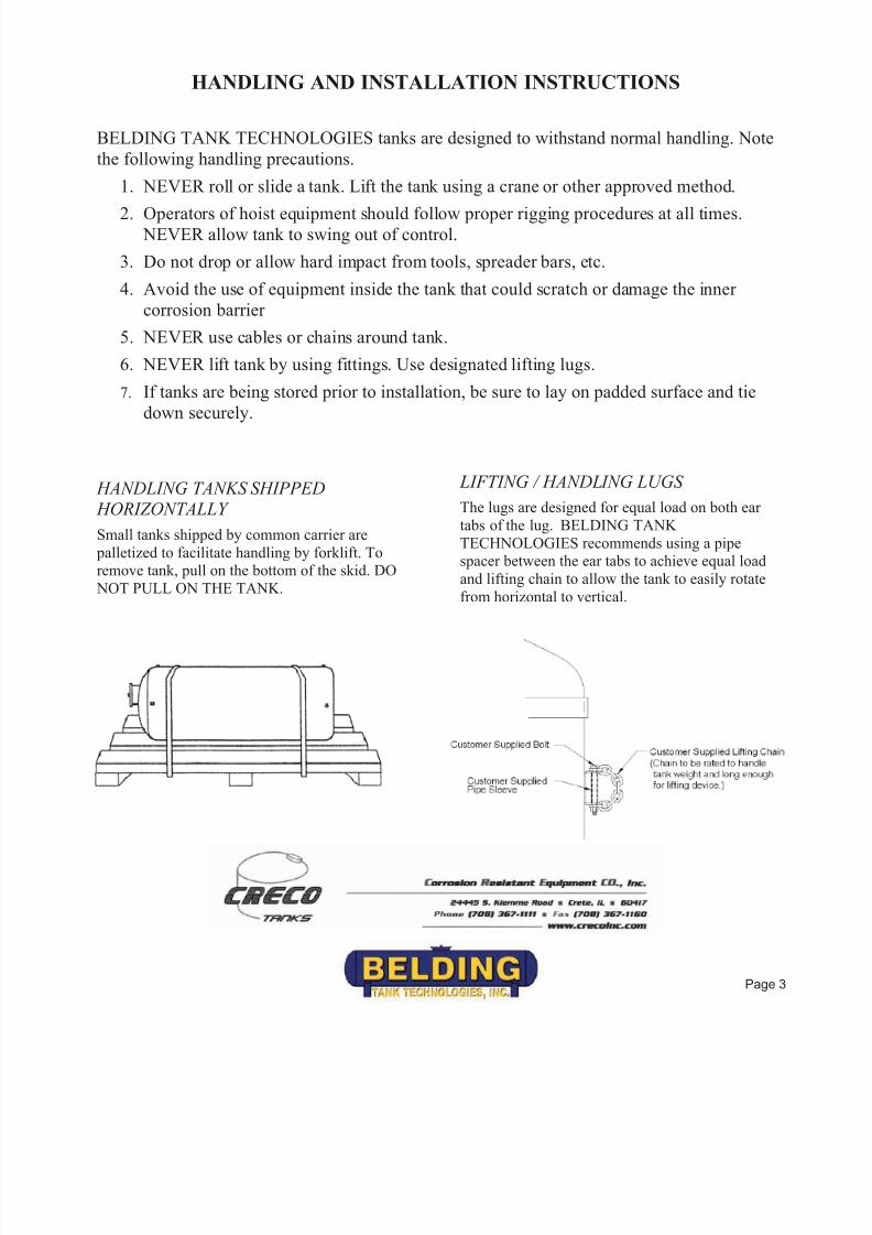
HANDLING TANKS SHIPPED HORIZONTALLY
Small tanks shipped by common carrier are
palletized to facilitate handling by forklift. Toremove tank, pull on the bottom of the skid. DO
NOT PULL ON THE TANK.
LIFTING / HANDLING LUGS
The lugs are designed for equal load on both ear
tabs of the lug. BELDING TANK
TECHNOLOGIES recommends using a pipespacer between the ear tabs to achieve equal load
and lifting chain to allow the tank to easily rotate
from horizontal to vertical.
Page 3
7/27/2019 Belding H&I O&M
http://slidepdf.com/reader/full/belding-hi-om 5/21
HANDLING AND INSTALLATION INSTRUCTIONS
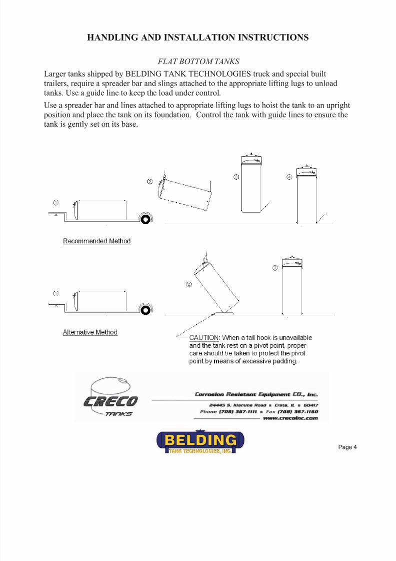
FLAT BOTTOM TANKS
Larger tanks shipped by BELDING TANK TECHNOLOGIES truck and special built
trailers, require a spreader bar and slings attached to the appropriate lifting lugs to unload
tanks. Use a guide line to keep the load under control.
Use a spreader bar and lines attached to appropriate lifting lugs to hoist the tank to an upright
position and place the tank on its foundation. Control the tank with guide lines to ensure the
tank is gently set on its base.
Page 4
7/27/2019 Belding H&I O&M
http://slidepdf.com/reader/full/belding-hi-om 6/21
HANDLING AND INSTALLATION INSTRUCTIONS
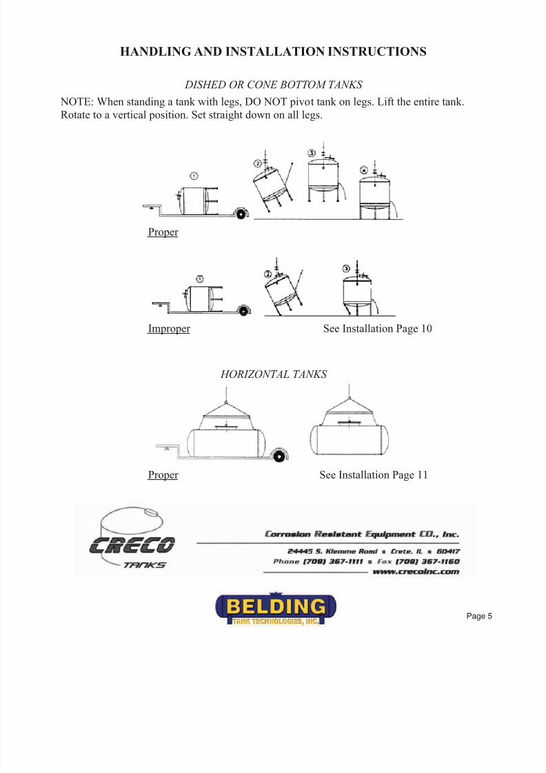
DISHED OR CONE BOTTOM TANKS
NOTE: When standing a tank with legs, DO NOT pivot tank on legs. Lift the entire tank.
Rotate to a vertical position. Set straight down on all legs.
Proper
Improper See Installation Page 10
HORIZONTAL TANKS
Proper See Installation Page 11
Page 5

7/27/2019 Belding H&I O&M
http://slidepdf.com/reader/full/belding-hi-om 7/21
HANDLING AND INSTALLATION INSTRUCTIONS
TANK BOTTOM SUPPORT PAD
BELDING TANK flat bottom and slope bottom tanks require continuous bottom support.
The most common support pad is a concrete slab. However, any other support structure with
sufficient strength to support the combined weight of the tank and its contents, with areasonable factor of safety, is acceptable. Design for bearing strength of support pad is the
responsibility of the purchaser. The support pad must exceed tank diameter by 6" minimum,
and be flat within +/- 1/16".
INSTALLATION NOTE: Support pad must be clean and free of all foreign objects prior to
settling tank in place.
TANK BOTTOM BUFFER PAD
Liquid grout such as concrete, epoxy, etc., MUST NOT be used under standard flat bottoms.BELDING TANK recommends a buffer pad between the tank support and tank bottom:
flexible elastomer or a minimum of two layers of 30 pound roofing felt. When applying the
roofing felt, be sure there are no overlaps or wrinkles causing ridges under the bottom. It is
the responsibility of the purchaser to see that tanks are properly installed. Any deviation from
the above outlined procedure must be approved by BELDING TANK TECHNOLOGIES or
it will void your warranty.
PIPE CONNECTIONS
Flexible pipe connections should be used wherever possible. If rigid piping must be used, be
certain it is self-supporting. If rigid piping is used and is not self-supporting, and results in
damage to a tank fitting, your warranty will be void. CAUTION: METALLIC FITTINGS
MUST NOT BE USED ON FRP NIPPLES OR COUPLINGS.
WATER FILL TESTING
BELDING TANK recommends that each tank be water filled (hydro tested) for a minimum 2 hour period atatmospheric pressure, after the tank is installed and prior to use.
Page 6
7/27/2019 Belding H&I O&M
http://slidepdf.com/reader/full/belding-hi-om 8/21
HANDLING AND INSTALLATION INSTRUCTIONS
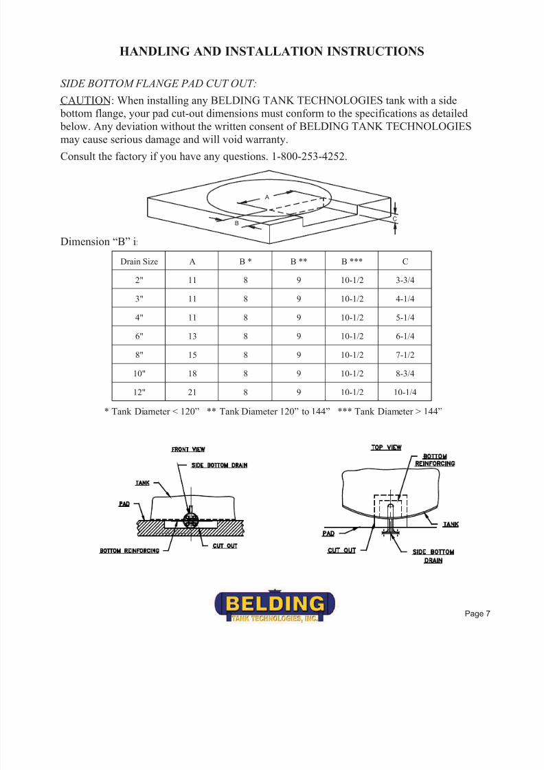
SIDE BOTTOM FLANGE PAD CUT OUT:
CAUTION: When installing any BELDING TANK TECHNOLOGIES tank with a side
bottom flange, your pad cut-out dimensions must conform to the specifications as detailed
below. Any deviation without the written consent of BELDING TANK TECHNOLOGIESmay cause serious damage and will void warranty.
Consult the factory if you have any questions. 1-800-253-4252.
Dimension “B” is taken from the sidewall of the tank.Drain Size A B * B ** B *** C
2" 11 8 9 10-1/2 3-3/4
3" 11 8 9 10-1/2 4-1/4
4" 11 8 9 10-1/2 5-1/4
6" 13 8 9 10-1/2 6-1/4
8" 15 8 9 10-1/2 7-1/2
10" 18 8 9 10-1/2 8-3/4
12" 21 8 9 10-1/2 10-1/4
* Tank Diameter < 120” ** Tank Diameter 120” to 144” *** Tank Diameter > 144”
A
BC
Page 7

7/27/2019 Belding H&I O&M
http://slidepdf.com/reader/full/belding-hi-om 9/21
HANDLING AND INSTALLATION INSTRUCTIONS
HOLD DOWN LUGS - Standard
The required hold down lugs are supplied as standard equipment on all BELDING TANK
TECHNOLOGIES tanks. Anchor bolts and hold down hardware are supplied by the
customer.
Preferred Method of Anchor Installation:
Expansion anchor or resin capsule anchor.
Belding Tank recommends the use of two nuts on the top of the lug. When the tank is
EMPTY, hand tighten the first nut onto the top of the lug. Hand tighten the second
“JAM” top nut onto the bottom nut. Then, using two wrenches lock the bottom nut
onto the top nut. Do not adjust after the tank is filled.
Do not over tighten hold down lugs.
INSTALLATION NOTE: Do not locate or pre-set anchor holes/bolts in the tank pad before
receipt of tank. BELDING TANK will not be responsible for pre-set anchor holes/bolts.
Customer Supplied
Anchoring System
Customer SuppliedPipe Sleeve
Page 8

7/27/2019 Belding H&I O&M
http://slidepdf.com/reader/full/belding-hi-om 10/21
HANDLING AND INSTALLATION INSTRUCTIONS
HOLD DOWN LUGS – Anchor “DOG” / Load Ledge
1. Position & set Anchors -- See Tank Drawing for position.
2. Minimum height of anchors above tank base = height of “DOG” + top plate + height of
(2) nuts + ½” minimum.
3. Position anchor “DOGS” over anchor bolts; locate dog ledge ¼” away from sidewall
and on top of load ledge & level “DOGS”; -- shim if needed.
4. When tank is empty fill anchor “DOG” box with non-shrink grout.
5. Put cover plate over anchor “DOG” box and hand- tighten bottom nut.
6. Hand tighten second “JAM” top nut onto the bottom nut.
7. Lock bottom nut onto the top nut. Do not adjust after tank is filled.
TO SUIT LG.
1/2 CLEARANCESHIM PER INSTRUCTIONS ABOVE.
CUSTOMER SUPPLIED
ANCHOR BOLTS
HAND TIGHTEN, LOCK WITH
JAM NUT PER INSTRUCTIONS
ABOVE.
ISO VIEW
TANK LOAD LEDGE
DOG LEDGE
1/4 CLEARANCE
Page 9

7/27/2019 Belding H&I O&M
http://slidepdf.com/reader/full/belding-hi-om 11/21
HANDLING AND INSTALLATION INSTRUCTIONS
DISHED BOTTOM TANKS
The pad surface must be smooth and level. Consideration must be given to the concentrated
nature (4-12 points) of the loading, the magnitude of which could require footings beneath
each leg to spread the load over a larger area. The design of footings is the responsibility of the purchaser.
The tank is designed to rely upon firm even support at each of its legs. In order to allow for
uneven pads, floors, and legs, the floor pads on each leg may require shims to insure uniform
support.
Consult factory if you have any questions. (1-800-253-4252)
Page 10

7/27/2019 Belding H&I O&M
http://slidepdf.com/reader/full/belding-hi-om 12/21
HANDLING AND INSTALLATION INSTRUCTIONS
HORIZONTAL TANK INSTALLATION
Installation of horizontal tanks is much the same as the dished bottom. Tanks are supplied
with the required number of steel support saddles. These saddles are to be placed under the
designated support rings. The saddles should be centered on the support ring and through the
centerline of the tank. Caution must be taken to insure that the tank support rings are in
contact with the bottom of the saddles.
Caution: Modification of saddles in any way voids your warranty.
SU PPOR T R I N G
SADD L E
1 5 0°
SADDLE
CO N T A C T
AREA
Page 11

7/27/2019 Belding H&I O&M
http://slidepdf.com/reader/full/belding-hi-om 13/21
OPERATION AND MAINTENANCE INSTRUCTIONS
Because of FIBERGLASS REINFORCED PLASTIC tanks unique, physical and structural characteristics;they are flexible, lightweight, corrosion resistant, and stronger than tanks made of other plastic materials.
Care, however, should be taken to follow the Handling and Installation instructions. Once the tank has been
properly installed and placed in service, BTT recommends regular routine inspections as a part of your preventative maintenance program.
The care and operation of FRP vessels rely mostly on common sense. To maximize trouble free service,
Belding Tank recommends:
1. Inspect your vessel thoroughly upon receipt.
2. Follow the Handling and Installation instruction.
3. Wash your vessel thoroughly w/detergent and rinse before putting in service (see FDA Requirements)
AFTER THE TANK IS PUT IN SERVICE:
1. Keep the vessel clean.
a. It will remain more aesthetically pleasing. b. If the tank is ever damaged, it will be evident.
2. Make a visual tank inspection inside and outside the tank every 6-12 months.
TANKS FOR FOOD APPLICATION:
BELDING TANK TECHNOLOGIES tanks will comply with U.S. Food, Drug and Cosmetic Act, as
amended, and applicable FDA regulations (21 cfr 177.2420). These tanks may be used as components
intended for repeated use in contact with food, subject to certain limitations described in that regulation.
BELDING TANK TECHNOLOGIES tanks are chemically acceptable in processing or storage areas for
contact with meat or poultry food products prepared under federal inspection and used at temperatures below180° F. This acceptance has been given by the United States Department of Agriculture.
Prior to shipping your tank, B.T.T. applies a (4) hour heat cure followed by a water rinse to the tank interior.
After installation and before your tank is put into service, attention to the following procedures is important
to achieve FDA compliance:
1. After tank installation, steam-treat or steep tank with hot water for 8-16 hours at 160° – 180° F. This
should remove all residual styrene from the laminate surface.
2. Wash the tank thoroughly with detergent and rinse it thoroughly.
3. Check state and local regulations for required compliance in addition to the above recommendations.
Page 12
7/27/2019 Belding H&I O&M
http://slidepdf.com/reader/full/belding-hi-om 14/21
OPERATION AND MAINTENANCE INSTRUCTIONS
AIR LOADING
“Tanks are often filled with liquids from tanker trucks by pressurizing the headspace above the liquid within
the tanker with compressed air to force tanker contents into the receiving tank. This is most typically done
when the liquid being transferred is a corrosive chemical, which could damage a pump. Although such a procedure eliminates the need for a pump, a possibility does exist that the pressurized air within the tanker
will follow the liquid into the receiving tank, and destroy the tank, due to excessive pressure.
Generally speaking, the tanker is connected to the receiving tank by a hose. The compressed air pushing
down on the liquid forces the liquid through the hose and into the receiving tank. The frictional resistance
offered by the hose and the fitting limits the maximum velocity of the liquid moving through the hose to areasonable value. The air displaced by the liquid entering the tank escapes through the normal vent provided
on the tank.
However, when the last of the liquid passes through the hose, the compressed air within the tanker rushes
through the hose at an extremely high velocity, because this air does not meet significant frictional resistance
in the hose, as the liquid does. This air enters the headspace in the receiving tank and expands with almostexplosive speed and force. The conventional tank vent cannot relive this excessive pressure within the tank.
When the pressure within the receiving tank exceeds that for which the tank is designed, either the tank head
blows off or some other portion of the tank ruptures.
Preferably, the person operating the tanker will interrupt the liquid flow before the last of the liquid leaves
the tanker, preventing the compressed air from entering the tank. However, through inattention or
carelessness, the operator will occasionally forget to interrupt the liquid at the "appropriate
time"…RESULT…POSSIBLE TANK FAILURE.”
The quoted description above is the possible occurrence when the tank is air loaded…IMPROPERLY;
proper procedure requires that the operator interrupt the liquid at the appropriate time. PROPER
PROCEDURE WILL NOT CAUSE TANK FAILURE.
To guard against tank failure when the tank is air loaded, opening the manhole cover is suggested. This
precaution, if the tank is air loaded improperly, does NOT eliminate the possibility of tank failure…but it
may lessen the possibility.
TO ELIMINATE TANK FAILURE DUE TO IMPROPER AIR LOADING:
A. BUILD A PRESSURE VESSEL, OR
B. ELIMINATE THE POSSIBILITY OF THE AIR PAD PRESSURE IN THE TANKER FROM
REACHING THE TANK INTERIOR BY:
1. Suspending the fill line above the manway (i.e. line is not to enter tank), OR…
2. Monitoring a flow meter to determine when the tanker will be empty, OR…
3. Install a "No-Flow" switch in tandem with a control valve.
Note: B.T.T. recommends consulting with a reputable firm in reference to flow meters and no flow switches.
If you have any questions or special circumstances that require discussion, please feel free to contact us at…
1-800-253-4252.
Page 13

7/27/2019 Belding H&I O&M
http://slidepdf.com/reader/full/belding-hi-om 15/21
OPERATION AND MAINTENANCE INSTRUCTIONS
MANHOLE BOLTING SEQUENCE
20” Side Manhole 24” Side Manhole
Drawings not to scale
Side Manhole Maximum Bolt Torque
Manhole PSI Rating (See Drawing)
Diameter 5 10 15 20 25 30 35 40
20” 16 ft. lbs. 20 ft. lbs. 20 ft. lbs. 20 ft. lbs. 20 ft. lbs. 20 ft. lbs. 20 ft. lbs. 20 ft. lbs.
24” 16 ft. lbs. 20 ft. lbs. 20 ft. lbs. 20 ft. lbs. 20 ft. lbs. 20 ft. lbs. 20 ft. lbs. 20 ft. lbs.
Page 14

7/27/2019 Belding H&I O&M
http://slidepdf.com/reader/full/belding-hi-om 16/21
OPERATION AND MAINTENANCE INSTRUCTIONS
MANHOLE BOLTING SEQUENCE
30” Side Manhole 36” Side Manhole
Drawings not to scale
Side Manhole Maximum Bolt Torque
Manhole PSI Rating (See Drawing)
Diameter 5 10 15 20 25 30 35 40
30” 25 ft. lbs. 43 ft. lbs. 43 ft. lbs. 43 ft. lbs. 43 ft. lbs. 43 ft. lbs. 43 ft. lbs. 43 ft. lbs.
36” 25 ft. lbs. 43 ft. lbs. 43 ft. lbs. 43 ft. lbs. 43 ft. lbs. 43 ft. lbs. 43 ft. lbs. 43 ft. lbs.
Page 15

7/27/2019 Belding H&I O&M
http://slidepdf.com/reader/full/belding-hi-om 17/21
OPERATION AND MAINTENANCE INSTRUCTIONS
FLANGED NOZZLE BOLTING SEQUENCE
CAUTION: A flange spacer MUST BE USED when bolting FRP flanges to raised face flanges. Use only
full face gaskets. Do NOT over torque flange bolts.
4 Bolt 8 Bolt 12 Bolt
Drawings not to scale
Flanged Nozzle PSI Rating & Maximum Torque
Diameter PSI Rating Maximum Torque
1” 125 14 ft. lbs.
1-1/2” 125 20 ft. lbs.
2” 125 41 ft. lbs.
2-1/2” 125 43 ft. lbs.
3” 125 43 ft. lbs.
4” 125 43 ft. lbs.
6” 100 77 ft. lbs.
8” 50 77 ft. lbs.
10” 50 98 ft. lbs.
12” 50 125 ft. lbs.
14” 25 105 ft. lbs.
Page 16

7/27/2019 Belding H&I O&M
http://slidepdf.com/reader/full/belding-hi-om 18/21
OPERATION AND MAINTENANCE INSTRUCTIONS
FLANGED NOZZLE BOLTING SEQUENCE
CAUTION: A flange spacer MUST BE USED when bolting FRP flanges to raised face flanges. Use only
full face gaskets. Do NOT over torque flange bolts.
16 Bolt 20 Bolt
Drawings not to scale
Flanged Nozzle PSI Rating & Maximum Torque
Diameter PSI Rating Maximum Torque
16” 25 102 ft. lbs.
18” 25 135 ft. lbs.
20” 25 131 ft. lbs.
24” 25 205 ft. lbs.
Page 17

7/27/2019 Belding H&I O&M
http://slidepdf.com/reader/full/belding-hi-om 19/21
OPERATION AND MAINTENANCE INSTRUCTIONS
Flanged Nozzle Allowable Loads Without Gussets
Size A B C
1 100 LBS. 50 FT./LBS. 100 LBS.
1-1/2 100 LBS. 100 FT./LBS. 100 LBS.
2 100 LBS. 100 FT./LBS. 100 LBS.
3 100 LBS. 100 FT./LBS. 100 LBS.
4 100 LBS. 100 FT./LBS. 100 LBS.
6 100 LBS. 100 FT./LBS. 100 LBS.
8 100 LBS. 100 FT./LBS. 100 LBS.
10 100 LBS. 100 FT./LBS. 100 LBS.
12 100 LBS. 100 FT./LBS. 100 LBS.
C
AB
Page 18

7/27/2019 Belding H&I O&M
http://slidepdf.com/reader/full/belding-hi-om 20/21
OPERATION AND MAINTENANCE INSTRUCTIONS
TANK USAGE
This tank has been sold for a specific chemical storage application. Before changing the
chemical environment, consult with BELDING TANK TECHNOLOGIES (your warranty
may be void without written authorization from B.T.T.)
BELDING TANK standard tanks are NOT designed for pressure or vacuum other than liquid
head. Be sure tanks are properly vented to avoid accidental pressure or vacuum.
Page 19

7/27/2019 Belding H&I O&M
http://slidepdf.com/reader/full/belding-hi-om 21/21
STATEMENT OF WARRANTY
Belding Tank Technologies, Inc. warrants its manufactured products against
any defects in the material and workmanship only for a period of (12) months
from shipment.
In the event that the purchaser asserts and Belding Tank Technologies, Inc.
agrees that the product is defective per this warranty, Belding Tank
Technologies, Inc. may, at its election replace, repair or credit the customer,
on the condition that the product is in possession of the original purchaser
and the product has been used for its originally intended purpose and design.
Any component parts that are on products manufactured and designed by
Belding Tank, are warranted only to the extent of the manufacturer of each
component part and to the extent as is enforceable by Belding Tank
Technologies, Inc.
Any alterations, modifications, or changes to any products manufactured or
supplied by Belding Tank Technologies, Inc., automatically voids this
warranty.
No warranty, either expressed or implied, is made by Belding Tank
Technologies, Inc. as to the fitness, merchantability, condition, capacity, or
efficiency of any products or goods sold, and no claims for labor or for
consequential damages will be allowed.
If purchaser attempts to repair product or take any other action, prior to
giving prompt notice and providing a reasonable opportunity for Belding
Tank Technologies, Inc. to inspect and correct said product, as deemed
necessary by the manufacturer, Belding Tank Technologies, Inc. shall not be
held liable for any expenses incurred by the purchaser.
No product may be returned for credit or replacement unless first authorized
by Belding Tank Technologies, Inc.
Belding Tank Technologies, Inc.’s liability and the purchaser’s exclusive
remedies are limited to those set forth in this warranty, to the exclusion of all
others.