beam columns
DESCRIPTION
beam columnTRANSCRIPT

University of SheffieldDepartment of Civil & Structural Engineering
BS5950:Part1:2000
Design of members with Axial Load and Moment

University of SheffieldDepartment of Civil & Structural Engineering
BS5950:Part1:2000
Aim
• consider the approach to members subject to axial load and bending adopted in BS 5950 Part 1
• consider the background theory where it is relevant to the understanding of the approach adopted
• recognise that the design of such members will be influenced by
• method of frame analysis• shape of the cross section used • type of restraint provided.

University of SheffieldDepartment of Civil & Structural Engineering
BS5950:Part1:2000
Must not fail due to….
Local buckling Inadequate local capacity (tension or compression and or bending)) Overall buckling
1. major or minor axis buckling due to axial load2. major axis buckling due to major axis bending + axial load3. minor axis buckling due to minor axis bending + axial load4. minor axis buckling due to major axis bending + axial load
University of SheffieldDepartment of Civil & Structural Engineering
BS5950:Part1:2000
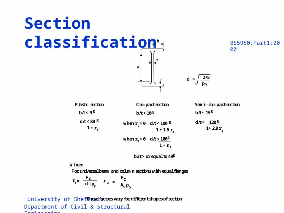
Section classificationb
t
T
d
b/t < 15
d/t < 120
Semi - compact section
1+ 2.0 r
b/t < 10
when r > 0 d/t < 100
Compact section
b/t < 9
d/t < 80
Plastic section
1 + r
Where
1 2 1 + 1.5 r 1
when r < 0 d/t < 100
1 + r 1
2
2
r 1
F
d t p y
c
For universal beam and column sections with equal flanges
=
275
y p
=
2
F
A p y
c = r
g
These factors vary for different shapes of section
but > or equal to 40

University of SheffieldDepartment of Civil & Structural Engineering
BS5950:Part1:2000
Local capacity
• Failure due to inadequate local capacity can occur in either tension or compression
• Where buckling is not a possibility the formulae are almost identical
1cy
y
cx
x
t
t
M
M
M
M
P
F
1cy
y
cx
x
yg
c
M
M
M
M
pA
F
• Tension
• Compression
University of SheffieldDepartment of Civil & Structural Engineering
BS5950:Part1:2000
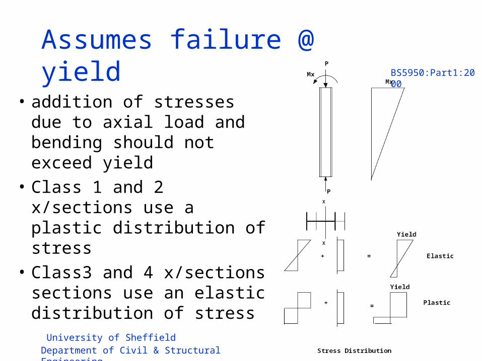
Assumes failure @ yield
• addition of stresses due to axial load and bending should not exceed yield
• Class 1 and 2 x/sections use a plastic distribution of stress
• Class3 and 4 x/sections sections use an elastic distribution of stress

University of SheffieldDepartment of Civil & Structural Engineering
BS5950:Part1:2000
Alternatively
• for both tension and compression plus moment• class 1 or 2 UB or UC
121
z
ry
y
z
rx
x
M
M
M
M
Mrx and Mry are the plastic moment capacity in the presence of axial load.
z1 and z2 are empirical values varying for the type of section.
z1 = 2.0 for UB, UC, CHS
z1 = 5/3 for RHS
z2 = 1.0 for UB,UC
z2 = 2.0 for CHS
z2 = 5/3 for RHS
University of SheffieldDepartment of Civil & Structural Engineering
BS5950:Part1:2000
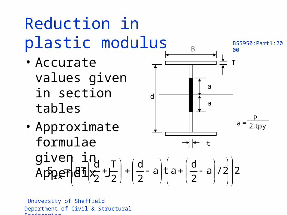
Reduction in plastic modulus
• Accurate values given in section tables
• Approximate formulae given in Appendix J
a
a
B
d
T
t
a = P
2.t.py
2/2a2
data
2
d
2
T
2
dBTS
rx

University of SheffieldDepartment of Civil & Structural Engineering
BS5950:Part1:2000
Compare the expressions
F
M
t
x
P t
M cx
1cy
y
cx
x
t
t
M
M
M
M
P
F
121
z
ry
y
z
rx
x
M
M
M
M

University of SheffieldDepartment of Civil & Structural Engineering
BS5950:Part1:2000
Tension members
• Generally not susceptible to buckling as axial tension prevents failure due to buckling caused by bending
• Theoretically possible to take account of this beneficial effect - expressions are complex
• Check bending effects independently - member treated as a laterally unrestrained beam
• Do this even when the tension and bending effects cannot occur independently

University of SheffieldDepartment of Civil & Structural Engineering
BS5950:Part1:2000
Compression – simplified method
• Combined gives:
P
Mx
P
Mx
X
X
P
My
P
My
y
y
1yy
yy
xy
xx
c
c
Zp
Mm
Zp
Mm
P
F
M
p x
cx
F
A +
y
1 x
g
c p Z
m x M
p y
cy
F
A +
y
1 y
g
c p Z
m y
Pc min of Agpcx and Agpcy
mx and my equivalent
uniform moment factors

University of SheffieldDepartment of Civil & Structural Engineering
BS5950:Part1:2000
Compression members- simplified method
• analogous to lateral torsional buckling in beams
• column buckles in a mode involving twisting and minor axis bending.
P
Mx
P
Mx
1yy
yy
b
xLT
cy
c
Zp
Mm
M
Mm
P
F
Pcy because considering buckling about the minor axis.
• significant for I and H sections buckling at low axial loads.
• not relevant for tubular sections which are not liable to suffer from lateral torsional buckling.

University of SheffieldDepartment of Civil & Structural Engineering
BS5950:Part1:2000
More exact approach- moments about major axis
F
F
d M F d
Secondary Moment
Primary Moment
M
M Moment diagram
Deflected shape
15.01
cx
c
cx
xx
cx
c
P
F
M
Mm
P
F
amplification factor allows for additional moment created by axial load at an eccentricity

University of SheffieldDepartment of Civil & Structural Engineering
BS5950:Part1:2000
LTB due to axial load and Mx
• In this case the amplification effect is less significant as the axial load is likely to be much less than the major axis strength.
1b
xLT
yc
c
M
Mm
P
F

University of SheffieldDepartment of Civil & Structural Engineering
BS5950:Part1:2000
Moments about minor axis
• In this case the amplification is more significant than about the major axis and the full value is used.
11
cy
c
cy
yy
y
c
P
F
M
Mm
P
F

University of SheffieldDepartment of Civil & Structural Engineering
BS5950:Part1:2000
Buckling about x-x due to My
• The amplification factor is negligible and the effect of the minor axis moment is small.
15.0 cy
yxy
xc
c
M
Mm
P
F

University of SheffieldDepartment of Civil & Structural Engineering
BS5950:Part1:2000
Moments about both axes
15.05.01
cy
yxy
cx
c
cx
xx
cx
c
M
Mm
P
F
M
Mm
P
FFor major axis buckling
11
cy
c
cy
yy
b
xLT
yc
c
P
F
M
Mm
M
Mm
P
F
For lateral torsional buckling
1)/1(
)/1(
)/1(
/5.01(
cyccy
cycyy
ccx
cxcxx
PFM
PFMm
PFM
PFMm
cx
For interactive buckling

University of SheffieldDepartment of Civil & Structural Engineering
BS5950:Part1:2000
Effect of moment shape
As applied moment tends towards double curvature, the secondary effects become less directly additive
F
F
M
F Secondary
Moment
Primary Moment
M b
M
F
d
M
F
Secondary Moment
Primary Moment
M
M
F
= +1.0 = -1.0
F
F
M
F Secondary
Moment
Primary Moment
M b
M
F
d
M
F
Secondary Moment
Primary Moment
M
M
F
= +1.0 = -1.0
Single curvature bending
Double curvature bending

University of SheffieldDepartment of Civil & Structural Engineering
BS5950:Part1:2000
• As a result the interaction expression plots increasingly higher
F Ag. Py
1.0
M/My 1.0
Strength interaction - zero slenderness
Column strength P=Pcr

University of SheffieldDepartment of Civil & Structural Engineering
BS5950:Part1:2000
• This change in the relationship can be represented by using an equivalent uniform moment factor m (very similar to that used for lateral torsional buckling of beams).
• Table 26 gives values and formula which can be used for all three modes of combined bending and axial load.

University of SheffieldDepartment of Civil & Structural Engineering
BS5950:Part1:2000
Design Summary
• For axial load and bending, check 1. Cross-section capacity
1cy
y
cx
x
t
t
M
M
M
M
P
FFor tension
1cy
y
cx
x
yg
c
M
M
M
M
pA
FFor compression
1
21
z
ry
y
z
rx
x
M
M
M
MMore exactly for class 1 and 2

University of SheffieldDepartment of Civil & Structural Engineering
BS5950:Part1:2000
Design Summary
2. BucklingTension – check cross-section capacity under tension
and moments (4.8.2.2 or 3) and buckling under moments alone (4.3).
Compression – check both
1yy
yy
xy
xx
c
c
Zp
Mm
Zp
Mm
P
F Buckling about either axis due to axial load and bending
1yy
yy
b
xLT
cy
c
Zp
Mm
M
Mm
P
F Buckling about the minor axis due to major axis bending and axial load
University of SheffieldDepartment of Civil & Structural Engineering
BS5950:Part1:2000
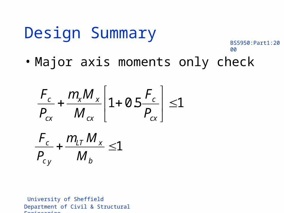
Design Summary
• Major axis moments only check
15.01
cx
c
cx
xx
cx
c
P
F
M
Mm
P
F
1b
xLT
yc
c
M
Mm
P
F

University of SheffieldDepartment of Civil & Structural Engineering
BS5950:Part1:2000
Design Summary
• Minor axis moments only check
11
cy
c
cy
yy
y
c
P
F
M
Mm
P
F
15.0 cy
yxy
xc
c
M
Mm
P
F

University of SheffieldDepartment of Civil & Structural Engineering
BS5950:Part1:2000
Design summary
• Axial load plus bi-axial moments
15.05.01
cy
yxy
cx
c
cx
xx
cx
c
M
Mm
P
F
M
Mm
P
F
11
cy
c
cy
yy
b
xLT
yc
c
P
F
M
Mm
M
Mm
P
F
1)/1(
)/1(
)/1(
/5.01(
cyccy
cycyy
ccx
cxcxx
PFM
PFMm
PFM
PFMm
cx

University of SheffieldDepartment of Civil & Structural Engineering
BS5950:Part1:2000

University of SheffieldDepartment of Civil & Structural Engineering
BS5950:Part1:2000
Special cases
• Tubular members – see 4.8.3.3.3– LTB may not be a problem
• Columns in simple structures– see 4.7.7– special simplified rules

University of SheffieldDepartment of Civil & Structural Engineering
BS5950:Part1:2000
Columns in simple structures
• Pin jointed braced fames• Nominal moments based on 100mm eccentricity• Equivalent uniform moment factors (m) = 1
1Zp
M
M
M
P
F
yy
y
bs
x
c
c
Mb calculated using LT as 0.5 L/ry
Distance between levels at which column is laterally restrained