bb, db, sb and dbb series - regula servis katalog/supravy/block_and... · 2016-04-30 · ... db, sb...
TRANSCRIPT
Block and Bleed ValvesBB, DB, SB and DBB Series
www.fitokgroup.com
FK-IC-GV-13-EN-160129
FITOK GroupFITOK GmbH (Headquarter)Sprendlinger Landstr. 115, 63069 Offenbach am Main, GermanyTel.: +49 69 8900 4498 Fax: +49 69 8900 4495
FITOK, Inc.13843 North Promenade Blvd., Suite 750, Stafford, Texas 77477, USATel.: +1 281 888 0077 Fax: +1 281 582 4051
FITOK Incorporated1-4F, Block C, Zone E, Yingtailong lndustrial Park, Dalang Street, Longhua District, Shenzhen, 518109, ChinaTel.: +86 755 2803 2500 Fax: +86 755 2803 2619
FITOK Middle East Oil Equipment Trading LLC208-209, Makateb Tower, Airport Road, P.O.Box 185412, Deira, Dubai, UAETel.: +971 4 2959 853 Fax: +971 4 2959 854
◎
◎
◎
◎
◎
◎
◎
◎
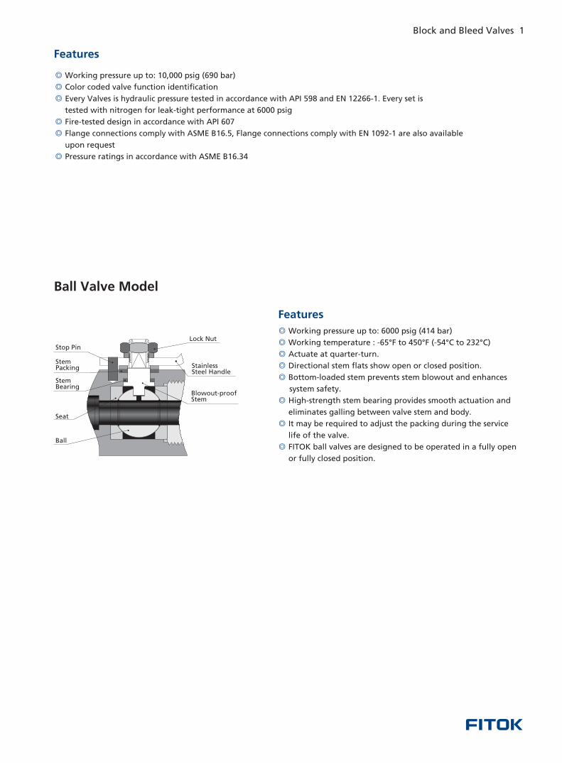
Working pressure up to:
Working temperature : -65°F to 450°F (-54°C to 232°C)
Actuate at quarter-turn.
Directional stem flats show open or closed position.
Bottom-loaded stem prevents stem blowout and enhances
system safety.
High-strength stem bearing provides smooth actuation and
eliminates galling between valve stem and body.
It may be required to adjust the packing during the service
life of the valve.
FITOK ball valves are designed to be operated in a fully open
or fully closed position.
6000 psig (414 bar)
Ball Valve Model
Features
Features
◎
◎
◎
◎
◎
◎
Working pressure up to:
Color coded valve function identification
Every Valves is hydraulic pressure tested in accordance with API 598 and EN 12266-1. Every set is
tested with nitrogen for leak-tight performance at 6000 psig
Fire-tested design in accordance with API 607
Flange connections comply with ASME B16.5, Flange connections comply with EN 1092-1 are also available
upon request
Pressure ratings in accordance with ASME B16.34
10,000 psig (690 bar)
Blowout-proofStem
Lock utN
Stainless Steel Handle
Ball
Seat
Stem Bearing
Stem Packing
Stop Pin
Block and Bleed Valves 1
Contents
11
10
04
12
BB Series: Single Block and Bleed Valves
DB Series: Double Block Valves
SB Series: Single Block Valves
DBB Series: Double Block and Bleed Valves
◎
◎
◎
◎
◎
◎
◎
◎
Working pressure up to:
Working temperature : -65°F to 450°F (-54°C to 232°C)
Actuate at quarter-turn.
Directional stem flats show open or closed position.
Bottom-loaded stem prevents stem blowout and enhances
system safety.
High-strength stem bearing provides smooth actuation and
eliminates galling between valve stem and body.
It may be required to adjust the packing during the service
life of the valve.
FITOK ball valves are designed to be operated in a fully open
or fully closed position.
6000 psig (414 bar)
Ball Valve Model
Features
Features
◎
◎
◎
◎
◎
◎
Working pressure up to:
Color coded valve function identification
Every Valves is hydraulic pressure tested in accordance with API 598 and EN 12266-1. Every set is
tested with nitrogen for leak-tight performance at 6000 psig
Fire-tested design in accordance with API 607
Flange connections comply with ASME B16.5, Flange connections comply with EN 1092-1 are also available
upon request
Pressure ratings in accordance with ASME B16.34
10,000 psig (690 bar)
Blowout-proofStem
Lock utN
Stainless Steel Handle
Ball
Seat
Stem Bearing
Stem Packing
Stop Pin
Block and Bleed Valves 1
Contents
11
10
04
12
BB Series: Single Block and Bleed Valves
DB Series: Double Block Valves
SB Series: Single Block Valves
DBB Series: Double Block and Bleed Valves
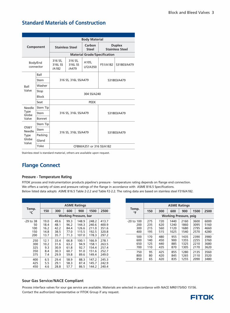
Sour Gas Service/NACE Compliant
Process interface valves for sour gas service are available. Materials are selected in accordance with NACE MR0175/ISO 15156.
Contact the authorized representative or if any request.FITOK Group
Standard Materials of Construction
Body Material
DuplexStainless Steel
Carbon Steel
Material Grade/Specification
Component Stainless Steel
Body/End
connector
316 SS,
316L SS
/A182
316 SS,
316L SS
/A479
A105,
LF2/A350F51/A182 S31803/A479
Ball
Valve
Needle TypeGlobeValve
OS&Y
Needle
Type
Globe
Valve
Ball
Stem
Washer
Stop
Block
Seat
Stem Tip
Stem
Bonnet
Stem Tip
Stem
Packing
Gland
Yoke
316 SS, 316L SS/A479
PEEK
S31803/A479
316 SS, 316L SS/A479 S31803/A479
316 SS, 316L SS/A479 S31803/A479
CF8M/A351 or 316 SS/A182
Stainless steel is standard material, others are available upon request.
2 Block and Bleed Valves Block and Bleed Valves 3
413 7 .400 9 .351 6 .320 8 .297 2 .
278 1 .263 5 .257 4 .252 7 .249 0 .
245 3 .242 9 .240 4 .
248 2 .240 6 .211 0 .192 5 .178 3 .
166 9 .158 1 .154 4 .151 6 .149 4 .
147 2 .145 7 .144 2 .
148 9 .144 3 .126 6 .115 5 .107 0 .
100 1 .94 9 .92 7 .91 0 .89 6 .
88 3 .87 4 .86 5 .
99 3 .96 2 .84 4 .77 0 .71 3 .
66 8 .63 2 .61 8 .60 7 .59 8 .
58 9 .58 3 .57 7 .
49 6 .48 1 .42 2 .38 5 .35 7 .
33 4 .31 6 .30 9 .30 3 .29 9 .
29 4 .29 1 .28 8 .
19.0 18 4 .16 2 .14 8 .13 7 .
12 1 .10 2 .9 3 .8 4 .7 4 .
6 5 .5 5 .4 6 .
Pressure - Temperature Rating
Temp. °C
ASME Ratings
150 300 600 900 1500 2500
Working Pressure, bar
- 38 29 to 50
100 150 200
250 300 325 350 375
400 425 450
6000 5160 4660 4280
3980 3760 3680 3620
3560 3520 3480
3600 3095 2795 2570
2390 2255 2210 2170
2135 2110 2090
2160 1860 1680 1540
1435 1355 1325 1305
1280 1265 1255
1440 1240 1120 1025
955 900 885 870
855 845 835
720 620 560 515
480 450 440 435
425 420 420
275 235 215 195
170 140 125 110
95 80 65
Temp.°F
ASME Ratings
150 300 600 900 1500 2500
Working Pressure, psig
-20 to 100 200 300 400
500 600 650 700
750 800 850
FITOK process and Instrumentation products pipeline's pressure - temperature rating depends on flange end connection.
We offers a variety of sizes and pressure ratings of the flange in accordance with ASME B16.5 Specifications.
Below listed data adopts ASME B16.5 Table 2-2.2 and Table F2-2.2. The rating data are based on stainless steel F316/A182.
Flange Connect
◎
◎
◎
◎
◎
◎
◎
Working pressure up to:
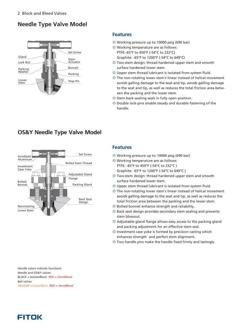
Working temperature are as follows:
PTFE:-65°F to 450°F (-54°C to 232°C)
Graphite: -65°F to 1200°F (-54°C to 649°C)
Two-stem design: thread hardened upper stem and smooth
surface hardened lower stem.
Upper stem thread lubricant is isolated from system fluid.
The non-rotating lower stem's linear instead of helical movement
avoids galling damage to the seat and tip, avoids galling damage
to the seat and tip, as well as reduces the total friction area betw-
een the packing and the lower stem.
Stem back seating seals in fully open position.
Double lock-pins enable steady and durable fastening of the
handle.
10000 psig (690 bar)
Needle Type Valve Model
Features
◎
◎
◎
◎
◎
◎
◎
◎
◎
◎
Working pressure up to:
Working temperature are as follows:
PTFE: -65°F to 450°F (-54°C to 232°C )
Graphite: -65°F to 1200°F (-54°C to 649°C )
Two-stem design: thread hardened upper stem and smooth
surface hardened lower stem.
Upper stem thread lubricant is isolated from system fluid.
The non-rotating lower stem's linear instead of helical movement
avoids galling damage to the seat and tip, as well as reduces the
total friction area between the packing and the lower stem.
Bolted bonnet enhance strength and reliability.
Back seat design provides secondary stem sealing and prevents
stem blowout.
Adjustable gland flange allows easy access to the packing gland
and packing adjustment for an effective stem seal.
Investment case yoke is formed by precision casting which
enhances strength and perfect stem alignment.
Two handle pins make the handle fixed firmly and lastingly.
10000 psig (690 bar)
Features
Handle colors indicate functions:
Needle and OS&Y valves:
BLACK = Isolate/Block RED = Vent/Bleed
Ball valves:
YELLOW = Isolate/Block RED = Vent/Bleed
Set Screw
Stem Actuator
Bonnet
Packing
Stop Pin
Gland
Lock Nut
Packing Washer
Lower Stem
Rolled Stem Thread
Adjustable Gland
Flange
Packing Gland
Nonrotating
Lower Stem
Anodized Aluminum
Investment Case Yoke
Bolted Bonnet
Back Seat Design
Set S crew
OS&Y Needle Type Valve Model
304 SS/A240
Sour Gas Service/NACE Compliant
Process interface valves for sour gas service are available. Materials are selected in accordance with NACE MR0175/ISO 15156.
Contact the authorized representative or if any request.FITOK Group
Standard Materials of Construction
Body Material
DuplexStainless Steel
Carbon Steel
Material Grade/Specification
Component Stainless Steel
Body/End
connector
316 SS,
316L SS
/A182
316 SS,
316L SS
/A479
A105,
LF2/A350F51/A182 S31803/A479
Ball
Valve
Needle TypeGlobeValve
OS&Y
Needle
Type
Globe
Valve
Ball
Stem
Washer
Stop
Block
Seat
Stem Tip
Stem
Bonnet
Stem Tip
Stem
Packing
Gland
Yoke
316 SS, 316L SS/A479
PEEK
S31803/A479
316 SS, 316L SS/A479 S31803/A479
316 SS, 316L SS/A479 S31803/A479
CF8M/A351 or 316 SS/A182
Stainless steel is standard material, others are available upon request.
2 Block and Bleed Valves Block and Bleed Valves 3
413 7 .400 9 .351 6 .320 8 .297 2 .
278 1 .263 5 .257 4 .252 7 .249 0 .
245 3 .242 9 .240 4 .
248 2 .240 6 .211 0 .192 5 .178 3 .
166 9 .158 1 .154 4 .151 6 .149 4 .
147 2 .145 7 .144 2 .
148 9 .144 3 .126 6 .115 5 .107 0 .
100 1 .94 9 .92 7 .91 0 .89 6 .
88 3 .87 4 .86 5 .
99 3 .96 2 .84 4 .77 0 .71 3 .
66 8 .63 2 .61 8 .60 7 .59 8 .
58 9 .58 3 .57 7 .
49 6 .48 1 .42 2 .38 5 .35 7 .
33 4 .31 6 .30 9 .30 3 .29 9 .
29 4 .29 1 .28 8 .
19.0 18 4 .16 2 .14 8 .13 7 .
12 1 .10 2 .9 3 .8 4 .7 4 .
6 5 .5 5 .4 6 .
Pressure - Temperature Rating
Temp. °C
ASME Ratings
150 300 600 900 1500 2500
Working Pressure, bar
- 38 29 to 50
100 150 200
250 300 325 350 375
400 425 450
6000 5160 4660 4280
3980 3760 3680 3620
3560 3520 3480
3600 3095 2795 2570
2390 2255 2210 2170
2135 2110 2090
2160 1860 1680 1540
1435 1355 1325 1305
1280 1265 1255
1440 1240 1120 1025
955 900 885 870
855 845 835
720 620 560 515
480 450 440 435
425 420 420
275 235 215 195
170 140 125 110
95 80 65
Temp.°F
ASME Ratings
150 300 600 900 1500 2500
Working Pressure, psig
-20 to 100 200 300 400
500 600 650 700
750 800 850
FITOK process and Instrumentation products pipeline's pressure - temperature rating depends on flange end connection.
We offers a variety of sizes and pressure ratings of the flange in accordance with ASME B16.5 Specifications.
Below listed data adopts ASME B16.5 Table 2-2.2 and Table F2-2.2. The rating data are based on stainless steel F316/A182.
Flange Connect
◎
◎
◎
◎
◎
◎
◎
Working pressure up to:
Working temperature are as follows:
PTFE:-65°F to 450°F (-54°C to 232°C)
Graphite: -65°F to 1200°F (-54°C to 649°C)
Two-stem design: thread hardened upper stem and smooth
surface hardened lower stem.
Upper stem thread lubricant is isolated from system fluid.
The non-rotating lower stem's linear instead of helical movement
avoids galling damage to the seat and tip, avoids galling damage
to the seat and tip, as well as reduces the total friction area betw-
een the packing and the lower stem.
Stem back seating seals in fully open position.
Double lock-pins enable steady and durable fastening of the
handle.
10000 psig (690 bar)
Needle Type Valve Model
Features
◎
◎
◎
◎
◎
◎
◎
◎
◎
◎
Working pressure up to:
Working temperature are as follows:
PTFE: -65°F to 450°F (-54°C to 232°C )
Graphite: -65°F to 1200°F (-54°C to 649°C )
Two-stem design: thread hardened upper stem and smooth
surface hardened lower stem.
Upper stem thread lubricant is isolated from system fluid.
The non-rotating lower stem's linear instead of helical movement
avoids galling damage to the seat and tip, as well as reduces the
total friction area between the packing and the lower stem.
Bolted bonnet enhance strength and reliability.
Back seat design provides secondary stem sealing and prevents
stem blowout.
Adjustable gland flange allows easy access to the packing gland
and packing adjustment for an effective stem seal.
Investment case yoke is formed by precision casting which
enhances strength and perfect stem alignment.
Two handle pins make the handle fixed firmly and lastingly.
10000 psig (690 bar)
Features
Handle colors indicate functions:
Needle and OS&Y valves:
BLACK = Isolate/Block RED = Vent/Bleed
Ball valves:
YELLOW = Isolate/Block RED = Vent/Bleed
Set Screw
Stem Actuator
Bonnet
Packing
Stop Pin
Gland
Lock Nut
Packing Washer
Lower Stem
Rolled Stem Thread
Adjustable Gland
Flange
Packing Gland
Nonrotating
Lower Stem
Anodized Aluminum
Investment Case Yoke
Bolted Bonnet
Back Seat Design
Set S crew
OS&Y Needle Type Valve Model
304 SS/A240
4 Block and Bleed Valves Block and Bleed Valves 5
Block: ball Bleed: needle (Valves Configuration: BN)
Vent
OutletProcess
Vent
OutletProcess
L (RF to NPT Connection)
L' (RTJ to NPT Connection)
B C
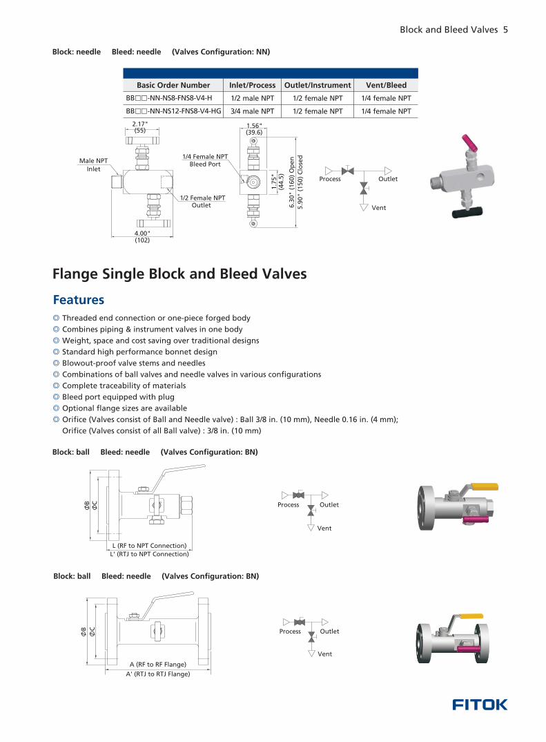
Block: needle Bleed: needle ( NN)Valves Configuration:
Inlet/ProcessBasic Order Number
BB -NN-NS12-FNS8-V4-HG□□ 3/4 male NPT 1/4 female NPT
Outlet/Instrument Vent/Bleed
BB -NN-NS8-FNS8-V4-H□□ 1/4 female NPT1/2 female NPT
1/2 female NPT
1/2 male NPT
Block: ball Bleed: needle (Valves Configuration: BN)
Vent
OutletProcessCB
A (RF to RF Flange)
A' (RTJ to RTJ Flange)
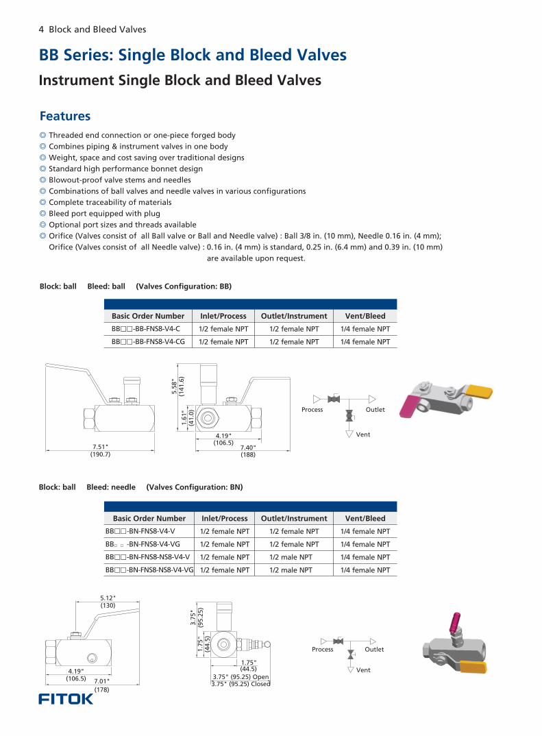
BB Series: Single Block and Bleed Valves
◎
◎
◎
◎
◎
◎
◎
◎
◎
◎
Threaded end connection or one-piece forged body
Combines piping & instrument valves in one body
Weight, space and cost saving over traditional designs
Standard high performance bonnet design
Blowout-proof valve stems and needles
Combinations of ball valves and needle valves in various configurations
Complete traceability of materials
Bleed port equipped with plug
Optional port sizes and threads available
Orifice (Valves consist of all Ball valve or Ball and Needle valve) : Ball 3/8 in. (10 mm), Needle 0.16 in. (4 mm);
Orifice (Valves consist of all Needle valve) : 0.16 in. (4 mm) is standard, 0.25 in. (6.4 mm) and 0.39 in. (10 mm)
are available upon request.
Features
Block: ball Bleed: ball (Valves Configuration: BB)
Inlet/ProcessBasic Order Number
BB -BB-FNS8-V4-CG□□ 1/2 female NPT 1/4 female NPT
Outlet/Instrument Vent/Bleed
BB -BB-FNS8-V4-C□□ 1/2 female NPT 1/2 female NPT
1/2 female NPT
1/4 female NPT
Block: ball Bleed: needle ( BN)Valves Configuration:
3.75" 95.25 ( ) Open3.75" 95.25( ) Closed
1.75" ( )44.5
3.7
5"
()
95.2
51.7
5"
()
44.5
5.12" (130)
7.01"
( )178
4.19" ( )106.5
Process Outlet
Vent
Inlet/ProcessBasic Order Number Outlet/Instrument Vent/Bleed
BB -BN-FNS8-V4-V□□
BB -BN-FNS8-V4-VG□□
BB -BN-FNS8-NS8-V4-V□□
BB -BN-FNS8-NS8-V4-VG□□
1/4 female NPT
1/4 female NPT
1/4 female NPT
1/4 female NPT
1/2 female NPT 1/2 female NPT
1/2 female NPT 1/2 female NPT
1/2 female NPT
1/2 female NPT 1/2 male NPT
1/2 male NPT
Instrument Single Block and Bleed Valves
Vent
OutletProcess
4.19" (106.5)
5.5
8"
(141.6
) 1
.61"
(4
1.0
)
7.40" (188)( )190.7
7.51"
4.00" ( )102
6.3
0"
(1
60
) O
pe
n
5.9
0"
(1
50
) C
lose
d
(39.6)1.56"
1.7
5"
(
)4
4.5
2.17" ( )55
Male NPT
Inlet
/2 Female NPT Outlet
1
1/4 Female NPTBleed Port
◎
◎
◎
◎
◎
◎
◎
◎
◎
◎
Threaded end connection or one-piece forged body
Combines piping & instrument valves in one body
Weight, space and cost saving over traditional designs
Standard high performance bonnet design
Blowout-proof valve stems and needles
Combinations of ball valves and needle valves in various configurations
Complete traceability of materials
Bleed port equipped with plug
Optional flange sizes are available
Orifice (Valves consist of Ball and Needle valve) : Ball 3/8 in. (10 mm), Needle 0.16 in. (4 mm);
Orifice (Valves consist of all Ball valve) : 3/8 in. (10 mm)
Features
Flange Single Block and Bleed Valves
4 Block and Bleed Valves Block and Bleed Valves 5
Block: ball Bleed: needle (Valves Configuration: BN)
Vent
OutletProcess
Vent
OutletProcess
L (RF to NPT Connection)
L' (RTJ to NPT Connection)
B C
Block: needle Bleed: needle ( NN)Valves Configuration:
Inlet/ProcessBasic Order Number
BB -NN-NS12-FNS8-V4-HG□□ 3/4 male NPT 1/4 female NPT
Outlet/Instrument Vent/Bleed
BB -NN-NS8-FNS8-V4-H□□ 1/4 female NPT1/2 female NPT
1/2 female NPT
1/2 male NPT
Block: ball Bleed: needle (Valves Configuration: BN)
Vent
OutletProcessCB
A (RF to RF Flange)
A' (RTJ to RTJ Flange)
BB Series: Single Block and Bleed Valves
◎
◎
◎
◎
◎
◎
◎
◎
◎
◎
Threaded end connection or one-piece forged body
Combines piping & instrument valves in one body
Weight, space and cost saving over traditional designs
Standard high performance bonnet design
Blowout-proof valve stems and needles
Combinations of ball valves and needle valves in various configurations
Complete traceability of materials
Bleed port equipped with plug
Optional port sizes and threads available
Orifice (Valves consist of all Ball valve or Ball and Needle valve) : Ball 3/8 in. (10 mm), Needle 0.16 in. (4 mm);
Orifice (Valves consist of all Needle valve) : 0.16 in. (4 mm) is standard, 0.25 in. (6.4 mm) and 0.39 in. (10 mm)
are available upon request.
Features
Block: ball Bleed: ball (Valves Configuration: BB)
Inlet/ProcessBasic Order Number
BB -BB-FNS8-V4-CG□□ 1/2 female NPT 1/4 female NPT
Outlet/Instrument Vent/Bleed
BB -BB-FNS8-V4-C□□ 1/2 female NPT 1/2 female NPT
1/2 female NPT
1/4 female NPT
Block: ball Bleed: needle ( BN)Valves Configuration:
3.75" 95.25 ( ) Open3.75" 95.25( ) Closed
1.75" ( )44.5
3.7
5"
()
95.2
51.7
5"
()
44.5
5.12" (130)
7.01"
( )178
4.19" ( )106.5
Process Outlet
Vent
Inlet/ProcessBasic Order Number Outlet/Instrument Vent/Bleed
BB -BN-FNS8-V4-V□□
BB -BN-FNS8-V4-VG□□
BB -BN-FNS8-NS8-V4-V□□
BB -BN-FNS8-NS8-V4-VG□□
1/4 female NPT
1/4 female NPT
1/4 female NPT
1/4 female NPT
1/2 female NPT 1/2 female NPT
1/2 female NPT 1/2 female NPT
1/2 female NPT
1/2 female NPT 1/2 male NPT
1/2 male NPT
Instrument Single Block and Bleed Valves
Vent
OutletProcess
4.19" (106.5)
5.5
8"
(141.6
) 1
.61"
(4
1.0
)
7.40" (188)( )190.7
7.51"
4.00" ( )102
6.3
0"
(1
60
) O
pe
n
5.9
0"
(1
50
) C
lose
d
(39.6)1.56"
1.7
5"
(
)4
4.5
2.17" ( )55
Male NPT
Inlet
/2 Female NPT Outlet
1
1/4 Female NPTBleed Port
◎
◎
◎
◎
◎
◎
◎
◎
◎
◎
Threaded end connection or one-piece forged body
Combines piping & instrument valves in one body
Weight, space and cost saving over traditional designs
Standard high performance bonnet design
Blowout-proof valve stems and needles
Combinations of ball valves and needle valves in various configurations
Complete traceability of materials
Bleed port equipped with plug
Optional flange sizes are available
Orifice (Valves consist of Ball and Needle valve) : Ball 3/8 in. (10 mm), Needle 0.16 in. (4 mm);
Orifice (Valves consist of all Ball valve) : 3/8 in. (10 mm)
Features
Flange Single Block and Bleed Valves
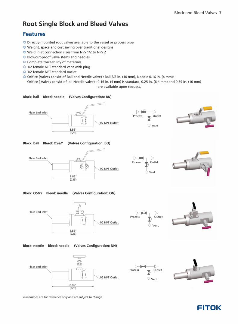
Root Single Block and Bleed Valves
◎
◎
◎
◎
◎
◎
◎
◎
Directly-mounted root valves available to the vessel or process pipe
Weight, space and cost saving over traditional designs
Weld inlet connection sizes from NPS 1/2 to NPS 2
Blowout-proof valve stems and needles
Complete traceability of materials
1/2 female NPT standard vent with plug
1/2 female NPT standard outlet
Orifice (Valves consist of Ball and Needle valve) : Ball 3/8 in. (10 mm), Needle 0.16 in. (4 mm);
Orifice ( Valves consist of all Needle valve) : 0.16 in. (4 mm) is standard, 0.25 in. (6.4 mm) and 0.39 in. (10 mm)
are available upon request.
Features
Block: ball Bleed: needle (Valves Configuration: BN)
Block: ball Bleed: OS&Y (Valves Configuration: BO)
Block: OS&Y Bleed: needle (Valves Configuration: ON)
Block: needle Bleed: needle (Valves Configuration: NN)
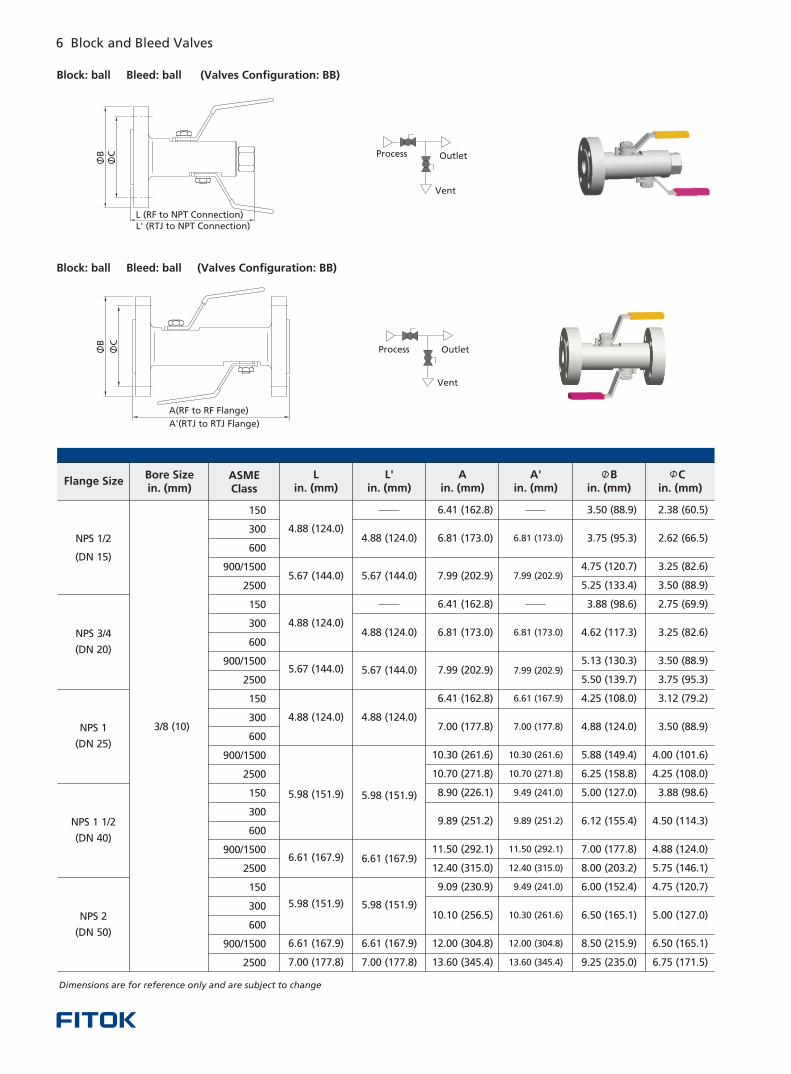
Dimensions are for reference only and are subject to change
Process Outlet
Vent1/2 NPT Outlet
Plain End Inlet
8.86" ( )225
Process
Vent
Outlet
Plain End Inlet
1/2 NPT Outlet
8.86" ( )225
Vent
OutletProcess
Plain End Inlet
1/2 NPT Outlet
8.86" ( )225
Process Outlet
Vent1/2 NPT Outlet
Plain End Inlet
8.86" ( )225
6 Block and Bleed Valves Block and Bleed Valves 7
Dimensions are for reference only and are subject to change
Flange SizeBore Sizein. (mm)
ASMEClass
Lin. (mm)
L'in. (mm)
Ain. (mm)
A'in. (mm)
Bin. (mm)
Cin. (mm)
NPS 3/4
(DN 20)
NPS 1
(DN 25)
NPS 1 1/2
(DN 40)
NPS 2
(DN 50)
3/8 (10)
150
300
600
900/1500
2500
150
300
600
900/1500
2500
150
300
600
900/1500
2500
150
300
600
900/1500
2500
150
300
600
900/1500
2500
2.38 (60.5)
2.62 (66.5)
3.25 (82.6)
3.50 (88.9)
2.75 (69.9)
3.25 (82.6)
3.50 (88.9)
3.75 (95.3)
3.12 (79.2)
3.50 (88.9)
4.00 (101.6)
4.25 (108.0)
3.88 (98.6)
4.50 (114.3)
4.88 (124.0)
5.75 (146.1)
4.75 (120.7)
5.00 (127.0)
6.50 (165.1)
6.75 (171.5)
3.50 (88.9)
3.75 (95.3)
4.75 (120.7)
5.25 (133.4)
3.88 (98.6)
4.62 (117.3)
5.13 (130.3)
5.50 (139.7)
4.25 (108.0)
4.88 (124.0)
5.88 (149.4)
6.25 (158.8)
5.00 (127.0)
6.12 (155.4)
7.00 (177.8)
8.00 (203.2)
6.00 (152.4)
6.50 (165.1)
8.50 (215.9)
9.25 (235.0)
6.81 (173.0)
7.99 (202.9)
6.81 (173.0)
7.99 (202.9)
6.61 (167.9)
7.00 (177.8)
10.30 (261.6)
10.70 (271.8)
9.49 (241.0)
9.89 (251.2)
11.50 (292.1)
12.40 (315.0)
9.49 (241.0)
10.30 (261.6)
12.00 (304.8)
13.60 (345.4)
6.41 (162.8)
6.81 (173.0)
7.99 (202.9)
6.41 (162.8)
6.81 (173.0)
7.99 (202.9)
6.41 (162.8)
7.00 (177.8)
10.30 (261.6)
10.70 (271.8)
8.90 (226.1)
9.89 (251.2)
11.50 (292.1)
12.40 (315.0)
9.09 (230.9)
10.10 (256.5)
12.00 (304.8)
13.60 (345.4)
4.88 (124.0)
5.67 (144.0)
4.88 (124.0)
5.67 (144.0)
4.88 (124.0)
5.98 (151.9)
6.61 (167.9)
5.98 (151.9)
6.61 (167.9)
7.00 (177.8)
4.88 (124.0)
5.67 (144.0)
4.88 (124.0)
5.67 (144.0)
4.88 (124.0)
5.98 (151.9)
6.61 (167.9)
5.98 (151.9)
6.61 (167.9)
7.00 (177.8)
Block: ball Bleed: ball (Valves Configuration: BB)
Process Outlet
Vent
A(RF to RF Flange)
A'(RTJ to RTJ Flange)
B C
NPS 1/2
(DN 15)
Block: ball Bleed: ball (Valves Configuration: BB)
Process Outlet
Vent
CB
L (RF to NPT Connection)L' (RTJ to NPT Connection)
Root Single Block and Bleed Valves
◎
◎
◎
◎
◎
◎
◎
◎
Directly-mounted root valves available to the vessel or process pipe
Weight, space and cost saving over traditional designs
Weld inlet connection sizes from NPS 1/2 to NPS 2
Blowout-proof valve stems and needles
Complete traceability of materials
1/2 female NPT standard vent with plug
1/2 female NPT standard outlet
Orifice (Valves consist of Ball and Needle valve) : Ball 3/8 in. (10 mm), Needle 0.16 in. (4 mm);
Orifice ( Valves consist of all Needle valve) : 0.16 in. (4 mm) is standard, 0.25 in. (6.4 mm) and 0.39 in. (10 mm)
are available upon request.
Features
Block: ball Bleed: needle (Valves Configuration: BN)
Block: ball Bleed: OS&Y (Valves Configuration: BO)
Block: OS&Y Bleed: needle (Valves Configuration: ON)
Block: needle Bleed: needle (Valves Configuration: NN)
Dimensions are for reference only and are subject to change
Process Outlet
Vent1/2 NPT Outlet
Plain End Inlet
8.86" ( )225
Process
Vent
Outlet
Plain End Inlet
1/2 NPT Outlet
8.86" ( )225
Vent
OutletProcess
Plain End Inlet
1/2 NPT Outlet
8.86" ( )225
Process Outlet
Vent1/2 NPT Outlet
Plain End Inlet
8.86" ( )225
6 Block and Bleed Valves Block and Bleed Valves 7
Dimensions are for reference only and are subject to change
Flange SizeBore Sizein. (mm)
ASMEClass
Lin. (mm)
L'in. (mm)
Ain. (mm)
A'in. (mm)
Bin. (mm)
Cin. (mm)
NPS 3/4
(DN 20)
NPS 1
(DN 25)
NPS 1 1/2
(DN 40)
NPS 2
(DN 50)
3/8 (10)
150
300
600
900/1500
2500
150
300
600
900/1500
2500
150
300
600
900/1500
2500
150
300
600
900/1500
2500
150
300
600
900/1500
2500
2.38 (60.5)
2.62 (66.5)
3.25 (82.6)
3.50 (88.9)
2.75 (69.9)
3.25 (82.6)
3.50 (88.9)
3.75 (95.3)
3.12 (79.2)
3.50 (88.9)
4.00 (101.6)
4.25 (108.0)
3.88 (98.6)
4.50 (114.3)
4.88 (124.0)
5.75 (146.1)
4.75 (120.7)
5.00 (127.0)
6.50 (165.1)
6.75 (171.5)
3.50 (88.9)
3.75 (95.3)
4.75 (120.7)
5.25 (133.4)
3.88 (98.6)
4.62 (117.3)
5.13 (130.3)
5.50 (139.7)
4.25 (108.0)
4.88 (124.0)
5.88 (149.4)
6.25 (158.8)
5.00 (127.0)
6.12 (155.4)
7.00 (177.8)
8.00 (203.2)
6.00 (152.4)
6.50 (165.1)
8.50 (215.9)
9.25 (235.0)
6.81 (173.0)
7.99 (202.9)
6.81 (173.0)
7.99 (202.9)
6.61 (167.9)
7.00 (177.8)
10.30 (261.6)
10.70 (271.8)
9.49 (241.0)
9.89 (251.2)
11.50 (292.1)
12.40 (315.0)
9.49 (241.0)
10.30 (261.6)
12.00 (304.8)
13.60 (345.4)
6.41 (162.8)
6.81 (173.0)
7.99 (202.9)
6.41 (162.8)
6.81 (173.0)
7.99 (202.9)
6.41 (162.8)
7.00 (177.8)
10.30 (261.6)
10.70 (271.8)
8.90 (226.1)
9.89 (251.2)
11.50 (292.1)
12.40 (315.0)
9.09 (230.9)
10.10 (256.5)
12.00 (304.8)
13.60 (345.4)
4.88 (124.0)
5.67 (144.0)
4.88 (124.0)
5.67 (144.0)
4.88 (124.0)
5.98 (151.9)
6.61 (167.9)
5.98 (151.9)
6.61 (167.9)
7.00 (177.8)
4.88 (124.0)
5.67 (144.0)
4.88 (124.0)
5.67 (144.0)
4.88 (124.0)
5.98 (151.9)
6.61 (167.9)
5.98 (151.9)
6.61 (167.9)
7.00 (177.8)
Block: ball Bleed: ball (Valves Configuration: BB)
Process Outlet
Vent
A(RF to RF Flange)
A'(RTJ to RTJ Flange)
B C
NPS 1/2
(DN 15)
Block: ball Bleed: ball (Valves Configuration: BB)
Process Outlet
Vent
CB
L (RF to NPT Connection)L' (RTJ to NPT Connection)
Block: needle Bleed: needle (Valves configuration: NN, Two Vents)
L (RF)L' (RTJ)
Vent
OutletProcess
B
A
Flange SizeBore Sizein. (mm)
ASMEClass
Lin. (mm)
L'in. (mm)
Ain. (mm)
Bin. (mm)
NPS 3/4
(DN 20)
NPS 1
(DN 25)
NPS 11/2
(DN 40)
NPS 2
(DN 50)
0.16 (4.0)
150
300
600
900/1500
2500
150
300
600
900/1500
2500
150
300
600
900/1500
2500
150
300
600
900/1500
2500
150
300
600
900/1500
2500
2.03 (51.6)
2.03 (51.6)
2.11 (53.5)
2.03 (51.6)
2.11 (53.5)
2.11 (53.5)
2.19 (55.5)
2.67 (67.9)
2.03 (51.6)
2.19 (55.5)
2.11 (53.5)
2.42 (61.5)
2.88 (73.4)
3.50 (88.9)
3.75 (95.2)
4.75 (120.7)
3.88 (98.6)
4.62 (117.3)
5.50 (139.7)
5.13 (130.3)
4.25 (108.0)
4.88 (124.0)
5.88 (149.4)
6.25 (158.8)
5.00 (127.0)
6.12 (155.5)
7.00 (177.8)
8.00 (203.2)
6.00 (152.4)
6.50 (165.1)
8.50 (215.9)
9.25 (235.0)
5.25 (133.4)
2.62 (66.5)
3.25 (82.5)
3.25 (82.6)
3.75 (95.2)
3.50 (88.9)
3.12 (79.2)
3.50 (88.9)
4.00 (101.6)
4.25 (108.0)
3.88 (98.6)
4.50 (114.3)
4.88 (124.0)
5.75 (146.1)
4.75 (120.7)
5.00 (127.0)
6.50 (165.1)
6.75 (171.5)
2.38 (60.5)
3.50 (88.9)
2.75 (69.8)
2.03 (51.6)
2.11 (53.5)
2.03 (51.6)
2.11 (53.5)
2.11 (53.5)
2.19 (55.5)
2.67 (67.9)
2.03 (51.6)
2.19 (55.5)
2.11 (53.5)
2.42 (61.5)
2.88 (73.4)
2.03 (51.6)
Dimensions are for reference only and are subject to change.
8 Block and Bleed Valves Block and Bleed Valves 9
NPS 1/2
(DN 15)
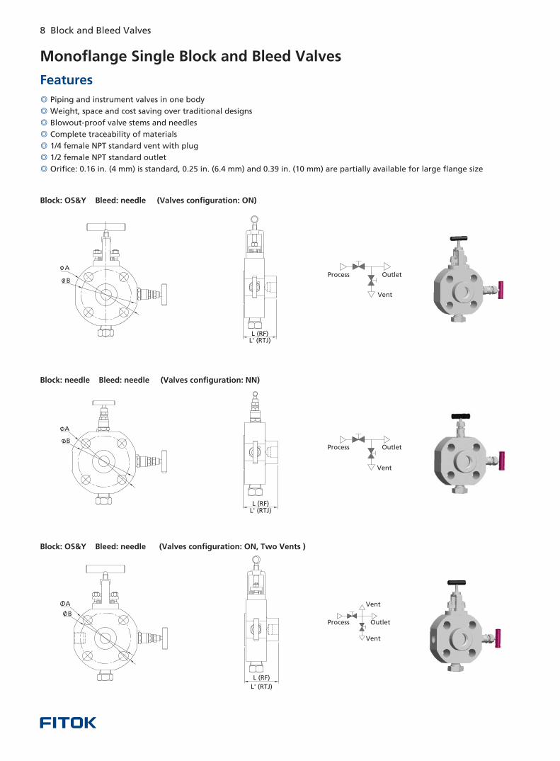
Monoflange Single Block and Bleed Valves
◎
◎
◎
◎
◎
◎
Piping and instrument valves in one body
over traditional designs
Blowout-proof valve stems and needles
Complete traceability of materials
1/4 female NPT standard vent with plug
1/2 female NPT standard outlet
Weight, space and cost saving
Orifice: 0.16 in. (4 mm) is standard, 0.25 in. (6.4 mm) and 0.39 in. (10 mm) are partially available for large flange size◎
Features
Block: OS&Y Bleed: needle (Valves configuration: ON)
Block: needle Bleed: needle (Valves configuration: NN)
Process Outlet
Vent
Vent
OutletProcess
L (RF)L (RTJ)'
L (RF)L (RTJ)'
Block: OS&Y Bleed: needle (Valves configuration: ON, Two Vents )
Process Outlet
Vent
L (RF)
L' (RTJ)
A
B
A
B
B
A
Vent
Vent
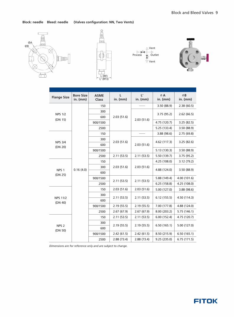
Block: needle Bleed: needle (Valves configuration: NN, Two Vents)
L (RF)L' (RTJ)
Vent
OutletProcess
B
A
Flange SizeBore Sizein. (mm)
ASMEClass
Lin. (mm)
L'in. (mm)
Ain. (mm)
Bin. (mm)
NPS 3/4
(DN 20)
NPS 1
(DN 25)
NPS 11/2
(DN 40)
NPS 2
(DN 50)
0.16 (4.0)
150
300
600
900/1500
2500
150
300
600
900/1500
2500
150
300
600
900/1500
2500
150
300
600
900/1500
2500
150
300
600
900/1500
2500
2.03 (51.6)
2.03 (51.6)
2.11 (53.5)
2.03 (51.6)
2.11 (53.5)
2.11 (53.5)
2.19 (55.5)
2.67 (67.9)
2.03 (51.6)
2.19 (55.5)
2.11 (53.5)
2.42 (61.5)
2.88 (73.4)
3.50 (88.9)
3.75 (95.2)
4.75 (120.7)
3.88 (98.6)
4.62 (117.3)
5.50 (139.7)
5.13 (130.3)
4.25 (108.0)
4.88 (124.0)
5.88 (149.4)
6.25 (158.8)
5.00 (127.0)
6.12 (155.5)
7.00 (177.8)
8.00 (203.2)
6.00 (152.4)
6.50 (165.1)
8.50 (215.9)
9.25 (235.0)
5.25 (133.4)
2.62 (66.5)
3.25 (82.5)
3.25 (82.6)
3.75 (95.2)
3.50 (88.9)
3.12 (79.2)
3.50 (88.9)
4.00 (101.6)
4.25 (108.0)
3.88 (98.6)
4.50 (114.3)
4.88 (124.0)
5.75 (146.1)
4.75 (120.7)
5.00 (127.0)
6.50 (165.1)
6.75 (171.5)
2.38 (60.5)
3.50 (88.9)
2.75 (69.8)
2.03 (51.6)
2.11 (53.5)
2.03 (51.6)
2.11 (53.5)
2.11 (53.5)
2.19 (55.5)
2.67 (67.9)
2.03 (51.6)
2.19 (55.5)
2.11 (53.5)
2.42 (61.5)
2.88 (73.4)
2.03 (51.6)
Dimensions are for reference only and are subject to change.
8 Block and Bleed Valves Block and Bleed Valves 9
NPS 1/2
(DN 15)
Monoflange Single Block and Bleed Valves
◎
◎
◎
◎
◎
◎
Piping and instrument valves in one body
over traditional designs
Blowout-proof valve stems and needles
Complete traceability of materials
1/4 female NPT standard vent with plug
1/2 female NPT standard outlet
Weight, space and cost saving
Orifice: 0.16 in. (4 mm) is standard, 0.25 in. (6.4 mm) and 0.39 in. (10 mm) are partially available for large flange size◎
Features
Block: OS&Y Bleed: needle (Valves configuration: ON)
Block: needle Bleed: needle (Valves configuration: NN)
Process Outlet
Vent
Vent
OutletProcess
L (RF)L (RTJ)'
L (RF)L (RTJ)'
Block: OS&Y Bleed: needle (Valves configuration: ON, Two Vents )
Process Outlet
Vent
L (RF)
L' (RTJ)
A
B
A
B
B
A
Vent
Vent
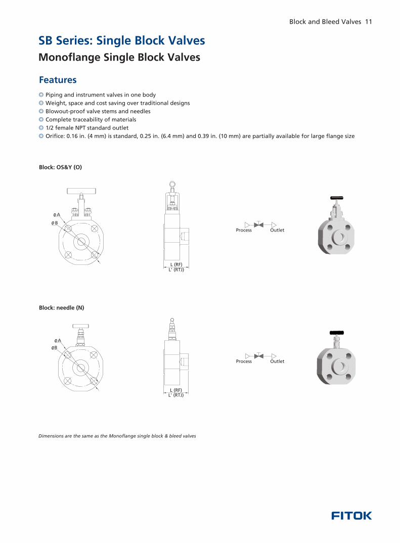
SB Series: Single Block Valves
◎
◎
◎
◎
◎
◎
Piping and instrument valves in one body
Weight, space and cost saving over traditional designs
Blowout-proof valve stems and needles
Complete traceability of materials
1/2 female NPT standard outlet
Orifice: 0.16 in. (4 mm) is standard, 0.25 in. (6.4 mm) and 0.39 in. (10 mm) are partially available for large flange size
Features
Block: OS&Y (O)
Block: needle (N)
Dimensions are the same as the Monoflange single block & bleed valves
OutletProcess
Process Outlet
B
A
A
B
L (RF)L' (RTJ)
L (RF)L' (RTJ)
10 Block and Bleed Valves Block and Bleed Valves 11
L (RF)L' (RTJ)
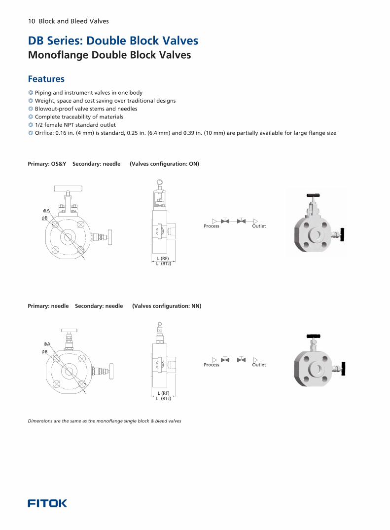
DB Series: Double Block Valves
◎
◎
◎
◎
◎
◎
Piping and instrument valves in one body
Weight, space and cost saving over traditional designs
Blowout-proof valve stems and needles
Complete traceability of materials
1/2 female NPT standard outlet
Orifice: 0.16 in. (4 mm) is standard, 0.25 in. (6.4 mm) and 0.39 in. (10 mm) are partially available for large flange size
Features
Primary: OS&Y Secondary: needle (Valves configuration: ON)
Primary: needle Secondary: needle (Valves configuration: NN)
Dimensions are the same as the monoflange single block & bleed valves
L (RF)L' (RTJ)
OutletProcess
OutletProcess
A
B
B
A
Monoflange Double Block Valves Monoflange Single Block Valves
SB Series: Single Block Valves
◎
◎
◎
◎
◎
◎
Piping and instrument valves in one body
Weight, space and cost saving over traditional designs
Blowout-proof valve stems and needles
Complete traceability of materials
1/2 female NPT standard outlet
Orifice: 0.16 in. (4 mm) is standard, 0.25 in. (6.4 mm) and 0.39 in. (10 mm) are partially available for large flange size
Features
Block: OS&Y (O)
Block: needle (N)
Dimensions are the same as the Monoflange single block & bleed valves
OutletProcess
Process Outlet
B
A
A
B
L (RF)L' (RTJ)
L (RF)L' (RTJ)
10 Block and Bleed Valves Block and Bleed Valves 11
L (RF)L' (RTJ)
DB Series: Double Block Valves
◎
◎
◎
◎
◎
◎
Piping and instrument valves in one body
Weight, space and cost saving over traditional designs
Blowout-proof valve stems and needles
Complete traceability of materials
1/2 female NPT standard outlet
Orifice: 0.16 in. (4 mm) is standard, 0.25 in. (6.4 mm) and 0.39 in. (10 mm) are partially available for large flange size
Features
Primary: OS&Y Secondary: needle (Valves configuration: ON)
Primary: needle Secondary: needle (Valves configuration: NN)
Dimensions are the same as the monoflange single block & bleed valves
L (RF)L' (RTJ)
OutletProcess
OutletProcess
A
B
B
A
Monoflange Double Block Valves Monoflange Single Block Valves
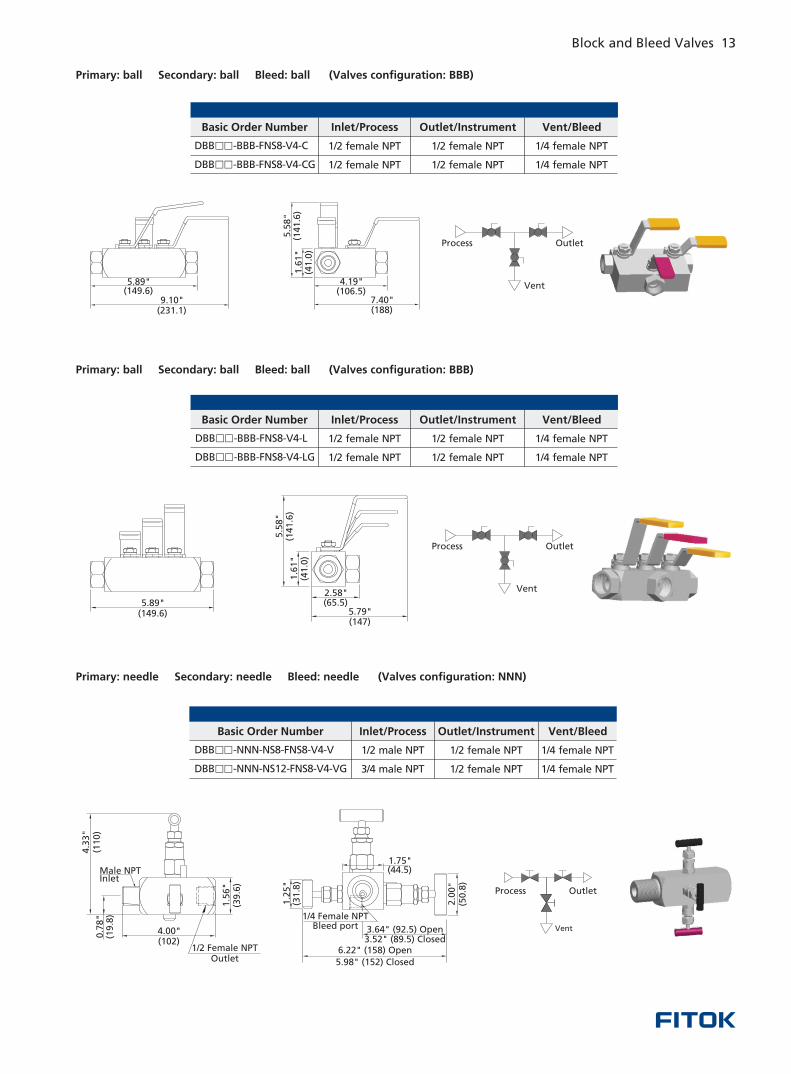
Primary: ball Secondary: ball Bleed: ball ( BBB)Valves configuration:
Primary: ball Secondary: ball Bleed: ball (Valves configuration: BBB)
Primary: needle Secondary: needle Bleed: needle (Valves configuration: NNN)
Outlet
Inlet/ProcessBasic Order Number
DBB -BBB-FNS8-V4-CG□□ 1/4 female NPT
Outlet/Instrument Vent/Bleed
DBB -BBB-FNS8-V4-C□□ 1/2 female NPT 1/4 female NPT
1/2 female NPT
1/2 female NPT
1/2 female NPT
Inlet/ProcessBasic Order Number
DBB -BBB-FNS8-V4-LG□□ 1/4 female NPT
Outlet/Instrument Vent/Bleed
DBB -BBB-FNS8-V4-L□□ 1/4 female NPT1/2 female NPT 1/2 female NPT
1/2 female NPT 1/2 female NPT
Inlet/ProcessBasic Order Number
DBB -NNN-NS12-FNS8-V4-VG□□ 3/4 male NPT 1/4 female NPT
Outlet/Instrument Vent/Bleed
DBB -NNN-NS8-FNS8-V4-V□□ 1/4 female NPT1/2 male NPT 1/2 female NPT
1/2 female NPT
1.6
1"
(
)4
1.0
5.5
8"
(
)1
41
.6
4.19" ( )106.5
7.40" ( )188
5.89" ( )149.6
9.10" ( )231.1
Process Outlet
Vent
5.89" ( )149.6 5.79"
( )147
2.58" ( )65.5
5.5
8"
()
141.6
1.6
1"
()
41.0
Process Outlet
Vent
OutletProcess
Vent
12 Block and Bleed Valves Block and Bleed Valves 13
1/4 Female NPTBleed port
1.75" ( )44.5
1.2
5"
()
31.8
6.22" 158( ) Open
5.98" 152( ) Closed
3.64" 92.5( ) Open3.52" 89.5( ) Closed
50.8
()
2.0
0"
Male NPTInlet
1/2 Female NPT Outlet
4.00" ( )102
1.5
6"
()
39.6
4.3
3"
()
110
0.7
8"
()
19.8
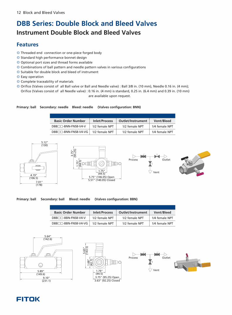
DBB Series: Double Block and Bleed Valves
◎
◎
◎
◎
◎
◎
◎
◎
Standard high performance bonnet design
Optional port sizes and thread forms available
Combinations of ball pattern and needle pattern valves in various configurations
Suitable for double block and bleed of instrument
Easy operation
Complete traceability of materials
Orifice (Valves consist of all Ball valve or Ball and Needle valve) : Ball 3/8 in. (10 mm), Needle 0.16 in. (4 mm);
Orifice (Valves consist of all Needle valve) : 0.16 in. (4 mm) is standard, 0.25 in. (6.4 mm) and 0.39 in. (10 mm)
are available upon request.
Threaded end connection or one-piece forged body
Instrument Double Block and Bleed Valves
Features
Primary: Secondary: Bleed: needle (Valves configuration: B N)ball needle N
Inlet/ProcessBasic Order Number
DBB -B N-FNS8-V4-VG□□ N 1/2 female NPT 1/2 female NPT 1/4 female NPT
Outlet/Instrument Vent/Bleed
DBB -B N-FNS8-V4-V□□ N 1/2 female NPT 1/2 female NPT 1/4 female NPT
Primary: ball Secondary: ball Bleed: needle ( BBN)Valves configuration:
Inlet/ProcessBasic Order Number
DBB -BBN-FNS8-V4-VG□□ 1/2 female NPT 1/2 female NPT 1/4 female NPT
Outlet/Instrument Vent/Bleed
DBB -BBN-FNS8-V4-V□□ 1/2 female NPT 1/2 female NPT 1/4 female NPT
3.75" 95.25( ) Open3.63" 92.25( ) Closed
1.79" ( )44.5
5.6
5"
()
143.5
1.6
8"
()
42.7
5.64" ( )142.6
9.10" ( )231.1
5.89" ( )149.6
Process Outlet
Vent
7.01" ( )178
5.12" ( )130
4.19" ( )106.5
3.7
5"
()
95.2
5
5.75" 146.05( ) Open5.51" 140.05( ) Closed
1.75" ( )44.5
1.7
5"
()
44.5
Process Outlet
Vent
Primary: ball Secondary: ball Bleed: ball ( BBB)Valves configuration:
Primary: ball Secondary: ball Bleed: ball (Valves configuration: BBB)
Primary: needle Secondary: needle Bleed: needle (Valves configuration: NNN)
Outlet
Inlet/ProcessBasic Order Number
DBB -BBB-FNS8-V4-CG□□ 1/4 female NPT
Outlet/Instrument Vent/Bleed
DBB -BBB-FNS8-V4-C□□ 1/2 female NPT 1/4 female NPT
1/2 female NPT
1/2 female NPT
1/2 female NPT
Inlet/ProcessBasic Order Number
DBB -BBB-FNS8-V4-LG□□ 1/4 female NPT
Outlet/Instrument Vent/Bleed
DBB -BBB-FNS8-V4-L□□ 1/4 female NPT1/2 female NPT 1/2 female NPT
1/2 female NPT 1/2 female NPT
Inlet/ProcessBasic Order Number
DBB -NNN-NS12-FNS8-V4-VG□□ 3/4 male NPT 1/4 female NPT
Outlet/Instrument Vent/Bleed
DBB -NNN-NS8-FNS8-V4-V□□ 1/4 female NPT1/2 male NPT 1/2 female NPT
1/2 female NPT
1.6
1"
(
)4
1.0
5.5
8"
(
)1
41
.6
4.19" ( )106.5
7.40" ( )188
5.89" ( )149.6
9.10" ( )231.1
Process Outlet
Vent
5.89" ( )149.6 5.79"
( )147
2.58" ( )65.5
5.5
8"
()
141.6
1.6
1"
()
41.0
Process Outlet
Vent
OutletProcess
Vent
12 Block and Bleed Valves Block and Bleed Valves 13
1/4 Female NPTBleed port
1.75" ( )44.5
1.2
5"
()
31.8
6.22" 158( ) Open
5.98" 152( ) Closed
3.64" 92.5( ) Open3.52" 89.5( ) Closed
50.8
()
2.0
0"
Male NPTInlet
1/2 Female NPT Outlet
4.00" ( )102
1.5
6"
()
39.6
4.3
3"
()
110
0.7
8"
()
19.8
DBB Series: Double Block and Bleed Valves
◎
◎
◎
◎
◎
◎
◎
◎
Standard high performance bonnet design
Optional port sizes and thread forms available
Combinations of ball pattern and needle pattern valves in various configurations
Suitable for double block and bleed of instrument
Easy operation
Complete traceability of materials
Orifice (Valves consist of all Ball valve or Ball and Needle valve) : Ball 3/8 in. (10 mm), Needle 0.16 in. (4 mm);
Orifice (Valves consist of all Needle valve) : 0.16 in. (4 mm) is standard, 0.25 in. (6.4 mm) and 0.39 in. (10 mm)
are available upon request.
Threaded end connection or one-piece forged body
Instrument Double Block and Bleed Valves
Features
Primary: Secondary: Bleed: needle (Valves configuration: B N)ball needle N
Inlet/ProcessBasic Order Number
DBB -B N-FNS8-V4-VG□□ N 1/2 female NPT 1/2 female NPT 1/4 female NPT
Outlet/Instrument Vent/Bleed
DBB -B N-FNS8-V4-V□□ N 1/2 female NPT 1/2 female NPT 1/4 female NPT
Primary: ball Secondary: ball Bleed: needle ( BBN)Valves configuration:
Inlet/ProcessBasic Order Number
DBB -BBN-FNS8-V4-VG□□ 1/2 female NPT 1/2 female NPT 1/4 female NPT
Outlet/Instrument Vent/Bleed
DBB -BBN-FNS8-V4-V□□ 1/2 female NPT 1/2 female NPT 1/4 female NPT
3.75" 95.25( ) Open3.63" 92.25( ) Closed
1.79" ( )44.5
5.6
5"
()
143.5
1.6
8"
()
42.7
5.64" ( )142.6
9.10" ( )231.1
5.89" ( )149.6
Process Outlet
Vent
7.01" ( )178
5.12" ( )130
4.19" ( )106.5
3.7
5"
()
95.2
5
5.75" 146.05( ) Open5.51" 140.05( ) Closed
1.75" ( )44.5
1.7
5"
()
44.5
Process Outlet
Vent
Primary: OS&Y Secondary: OS&Y Bleed: needle (Valves configuration: OON)
A (RF to RF Flange)A' (RTJ to RTJ Flange)
B C
L (RF to NPT Connection)L' (RTJ to NPT Connection)
CB
Flange SizeBore Sizein. (mm)
ASMEClass
Lin. (mm)
L'in. (mm)
Ain. (mm)
A'in. (mm)
Bin. (mm)
Cin. (mm)
NPS 3/4
(DN 20)
NPS 1
(DN 25)
NPS 11/2
(DN 40)
NPS 2
(DN 50)
0.39
(10)
150
300
600
900/1500
2500
150
300
600
900/1500
2500
150
300
600
900/1500
2500
150
300
600
900/1500
2500
150
300
600
900/1500
2500
2.38 (60.5)
2.62 (66.5)
3.25 (82.6)
3.50 (88.9)
2.75 (69.9)
3.25 (82.6)
3.50 (88.9)
3.75 (95.3)
3.12 (79.2)
3.50 (88.9)
4.00 (101.6)
4.25 (108.0)
3.88 (98.6)
4.50 (114.3)
4.88 (124.0)
5.75 (146.1)
4.75 (120.7)
5.00 (127.0)
6.50 (165.1)
6.75 (171.5)
3.50 (88.9)
3.75 (95.3)
4.75 (120.7)
5.25 (133.4)
3.88 (98.6)
4.62 (117.3)
5.13 (130.3)
5.50 (139.7)
4.25 (108.0)
4.88 (124.0)
5.88 (149.4)
6.25 (158.8)
5.00 (127.0)
6.12 (155.4)
7.00 (177.8)
8.00 (203.2)
6.00 (152.4)
6.50 (165.1)
8.50 (215.9)
9.25 (235.0)
6.81 (173.0)
7.99 (202.9)
6.81 (173.0)
7.99 (202.9)
6.61 (167.9)
7.00 (177.8)
10.30 (261.6)
10.70 (271.8)
9.49 (241.0)
9.89 (251.2)
11.50 (292.1)
12.40 (315.0)
9.49 (241.0)
10.30 (261.6)
12.00 (304.8)
13.60 (345.4)
6.41 (162.8)
6.81 (173.0)
7.99 (202.9)
6.41 (162.8)
6.81 (173.0)
7.99 (202.9)
6.41 (162.8)
7.00 (177.8)
10.30 (261.6)
10.70 (271.8)
8.90 (226.1)
9.89 (251.2)
11.50 (292.1)
12.40 (315.0)
9.09 (230.9)
10.10 (256.5)
12.00 (304.8)
13.60 (345.4)
4.88 (124.0)
5.60 (142.2)
4.88 (124.0)
5.60 (142.2)
4.88 (124.0)
5.98 (151.9)
6.61 (167.9)
5.98 (151.9)
6.61 (167.9)
7.00 (177.8)
4.88 (124.0)
5.60 (142.2)
4.88 (124.0)
5.60 (142.2)
4.88 (124.0)
5.98 (151.9)
6.61 (167.9)
5.98 (151.9)
6.61 (167.9)
7.00 (177.8)
14 Block and Bleed Valves Block and Bleed Valves 15
NPS 1/2
(DN 15)
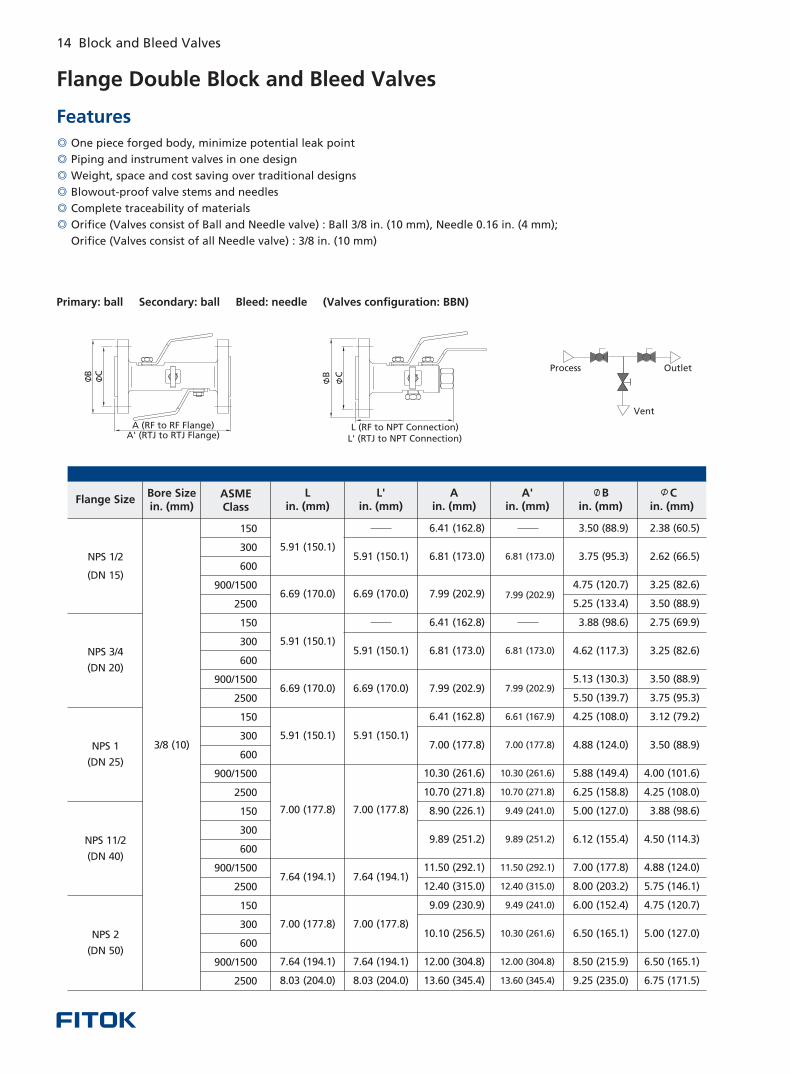
◎
◎
◎
◎
◎
◎
One piece forged body, minimize potential leak point
Piping and instrument valves in one design
Weight, space and cost saving over traditional designs
Blowout-proof valve stems and needles
Complete traceability of materials
Orifice (Valves consist of Ball and Needle valve) : Ball 3/8 in. (10 mm), Needle 0.16 in. (4 mm);
Orifice (Valves consist of all Needle valve) : 3/8 in. (10 mm)
Flange Double Block and Bleed Valves
Features
Primary: ball Secondary: ball Bleed: needle (Valves configuration: BBN)
L (RF to NPT Connection)L' (RTJ to NPT Connection)
B CCB
A (RF to RF Flange)A' (RTJ to RTJ Flange)
Process Outlet
Vent
Flange SizeBore Sizein. (mm)
ASMEClass
Lin. (mm)
L'in. (mm)
Ain. (mm)
A'in. (mm)
Bin. (mm)
Cin. (mm)
NPS 3/4
(DN 20)
NPS 1
(DN 25)
NPS 11/2
(DN 40)
NPS 2
(DN 50)
3/8 (10)
150
300
600
900/1500
2500
150
300
600
900/1500
2500
150
300
600
900/1500
2500
150
300
600
900/1500
2500
150
300
600
900/1500
2500
2.38 (60.5)
2.62 (66.5)
3.25 (82.6)
3.50 (88.9)
2.75 (69.9)
3.25 (82.6)
3.50 (88.9)
3.75 (95.3)
3.12 (79.2)
3.50 (88.9)
4.00 (101.6)
4.25 (108.0)
3.88 (98.6)
4.50 (114.3)
4.88 (124.0)
5.75 (146.1)
4.75 (120.7)
5.00 (127.0)
6.50 (165.1)
6.75 (171.5)
3.50 (88.9)
3.75 (95.3)
4.75 (120.7)
5.25 (133.4)
3.88 (98.6)
4.62 (117.3)
5.13 (130.3)
5.50 (139.7)
4.25 (108.0)
4.88 (124.0)
5.88 (149.4)
6.25 (158.8)
5.00 (127.0)
6.12 (155.4)
7.00 (177.8)
8.00 (203.2)
6.00 (152.4)
6.50 (165.1)
8.50 (215.9)
9.25 (235.0)
6.81 (173.0)
7.99 (202.9)
6.81 (173.0)
7.99 (202.9)
6.61 (167.9)
7.00 (177.8)
10.30 (261.6)
10.70 (271.8)
9.49 (241.0)
9.89 (251.2)
11.50 (292.1)
12.40 (315.0)
9.49 (241.0)
10.30 (261.6)
12.00 (304.8)
13.60 (345.4)
6.41 (162.8)
6.81 (173.0)
7.99 (202.9)
6.41 (162.8)
6.81 (173.0)
7.99 (202.9)
6.41 (162.8)
7.00 (177.8)
10.30 (261.6)
10.70 (271.8)
8.90 (226.1)
9.89 (251.2)
11.50 (292.1)
12.40 (315.0)
9.09 (230.9)
10.10 (256.5)
12.00 (304.8)
13.60 (345.4)
5.91 (150.1)
6.69 (170.0)
5.91 (150.1)
6.69 (170.0)
5.91 (150.1)
7.00 (177.8)
7.64 (194.1)
7.00 (177.8)
7.64 (194.1)
8.03 (204.0)
5.91 (150.1)
6.69 (170.0)
5.91 (150.1)
6.69 (170.0)
5.91 (150.1)
7.00 (177.8)
7.64 (194.1)
7.00 (177.8)
7.64 (194.1)
8.03 (204.0)
NPS 1/2
(DN 15)
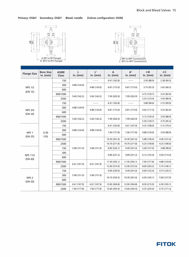
Primary: OS&Y Secondary: OS&Y Bleed: needle (Valves configuration: OON)
A (RF to RF Flange)A' (RTJ to RTJ Flange)
B C
L (RF to NPT Connection)L' (RTJ to NPT Connection)
CB
Flange SizeBore Sizein. (mm)
ASMEClass
Lin. (mm)
L'in. (mm)
Ain. (mm)
A'in. (mm)
Bin. (mm)
Cin. (mm)
NPS 3/4
(DN 20)
NPS 1
(DN 25)
NPS 11/2
(DN 40)
NPS 2
(DN 50)
0.39
(10)
150
300
600
900/1500
2500
150
300
600
900/1500
2500
150
300
600
900/1500
2500
150
300
600
900/1500
2500
150
300
600
900/1500
2500
2.38 (60.5)
2.62 (66.5)
3.25 (82.6)
3.50 (88.9)
2.75 (69.9)
3.25 (82.6)
3.50 (88.9)
3.75 (95.3)
3.12 (79.2)
3.50 (88.9)
4.00 (101.6)
4.25 (108.0)
3.88 (98.6)
4.50 (114.3)
4.88 (124.0)
5.75 (146.1)
4.75 (120.7)
5.00 (127.0)
6.50 (165.1)
6.75 (171.5)
3.50 (88.9)
3.75 (95.3)
4.75 (120.7)
5.25 (133.4)
3.88 (98.6)
4.62 (117.3)
5.13 (130.3)
5.50 (139.7)
4.25 (108.0)
4.88 (124.0)
5.88 (149.4)
6.25 (158.8)
5.00 (127.0)
6.12 (155.4)
7.00 (177.8)
8.00 (203.2)
6.00 (152.4)
6.50 (165.1)
8.50 (215.9)
9.25 (235.0)
6.81 (173.0)
7.99 (202.9)
6.81 (173.0)
7.99 (202.9)
6.61 (167.9)
7.00 (177.8)
10.30 (261.6)
10.70 (271.8)
9.49 (241.0)
9.89 (251.2)
11.50 (292.1)
12.40 (315.0)
9.49 (241.0)
10.30 (261.6)
12.00 (304.8)
13.60 (345.4)
6.41 (162.8)
6.81 (173.0)
7.99 (202.9)
6.41 (162.8)
6.81 (173.0)
7.99 (202.9)
6.41 (162.8)
7.00 (177.8)
10.30 (261.6)
10.70 (271.8)
8.90 (226.1)
9.89 (251.2)
11.50 (292.1)
12.40 (315.0)
9.09 (230.9)
10.10 (256.5)
12.00 (304.8)
13.60 (345.4)
4.88 (124.0)
5.60 (142.2)
4.88 (124.0)
5.60 (142.2)
4.88 (124.0)
5.98 (151.9)
6.61 (167.9)
5.98 (151.9)
6.61 (167.9)
7.00 (177.8)
4.88 (124.0)
5.60 (142.2)
4.88 (124.0)
5.60 (142.2)
4.88 (124.0)
5.98 (151.9)
6.61 (167.9)
5.98 (151.9)
6.61 (167.9)
7.00 (177.8)
14 Block and Bleed Valves Block and Bleed Valves 15
NPS 1/2
(DN 15)
◎
◎
◎
◎
◎
◎
One piece forged body, minimize potential leak point
Piping and instrument valves in one design
Weight, space and cost saving over traditional designs
Blowout-proof valve stems and needles
Complete traceability of materials
Orifice (Valves consist of Ball and Needle valve) : Ball 3/8 in. (10 mm), Needle 0.16 in. (4 mm);
Orifice (Valves consist of all Needle valve) : 3/8 in. (10 mm)
Flange Double Block and Bleed Valves
Features
Primary: ball Secondary: ball Bleed: needle (Valves configuration: BBN)
L (RF to NPT Connection)L' (RTJ to NPT Connection)
B CCB
A (RF to RF Flange)A' (RTJ to RTJ Flange)
Process Outlet
Vent
Flange SizeBore Sizein. (mm)
ASMEClass
Lin. (mm)
L'in. (mm)
Ain. (mm)
A'in. (mm)
Bin. (mm)
Cin. (mm)
NPS 3/4
(DN 20)
NPS 1
(DN 25)
NPS 11/2
(DN 40)
NPS 2
(DN 50)
3/8 (10)
150
300
600
900/1500
2500
150
300
600
900/1500
2500
150
300
600
900/1500
2500
150
300
600
900/1500
2500
150
300
600
900/1500
2500
2.38 (60.5)
2.62 (66.5)
3.25 (82.6)
3.50 (88.9)
2.75 (69.9)
3.25 (82.6)
3.50 (88.9)
3.75 (95.3)
3.12 (79.2)
3.50 (88.9)
4.00 (101.6)
4.25 (108.0)
3.88 (98.6)
4.50 (114.3)
4.88 (124.0)
5.75 (146.1)
4.75 (120.7)
5.00 (127.0)
6.50 (165.1)
6.75 (171.5)
3.50 (88.9)
3.75 (95.3)
4.75 (120.7)
5.25 (133.4)
3.88 (98.6)
4.62 (117.3)
5.13 (130.3)
5.50 (139.7)
4.25 (108.0)
4.88 (124.0)
5.88 (149.4)
6.25 (158.8)
5.00 (127.0)
6.12 (155.4)
7.00 (177.8)
8.00 (203.2)
6.00 (152.4)
6.50 (165.1)
8.50 (215.9)
9.25 (235.0)
6.81 (173.0)
7.99 (202.9)
6.81 (173.0)
7.99 (202.9)
6.61 (167.9)
7.00 (177.8)
10.30 (261.6)
10.70 (271.8)
9.49 (241.0)
9.89 (251.2)
11.50 (292.1)
12.40 (315.0)
9.49 (241.0)
10.30 (261.6)
12.00 (304.8)
13.60 (345.4)
6.41 (162.8)
6.81 (173.0)
7.99 (202.9)
6.41 (162.8)
6.81 (173.0)
7.99 (202.9)
6.41 (162.8)
7.00 (177.8)
10.30 (261.6)
10.70 (271.8)
8.90 (226.1)
9.89 (251.2)
11.50 (292.1)
12.40 (315.0)
9.09 (230.9)
10.10 (256.5)
12.00 (304.8)
13.60 (345.4)
5.91 (150.1)
6.69 (170.0)
5.91 (150.1)
6.69 (170.0)
5.91 (150.1)
7.00 (177.8)
7.64 (194.1)
7.00 (177.8)
7.64 (194.1)
8.03 (204.0)
5.91 (150.1)
6.69 (170.0)
5.91 (150.1)
6.69 (170.0)
5.91 (150.1)
7.00 (177.8)
7.64 (194.1)
7.00 (177.8)
7.64 (194.1)
8.03 (204.0)
NPS 1/2
(DN 15)
16 Block and Bleed Valves Block and Bleed Valves 17
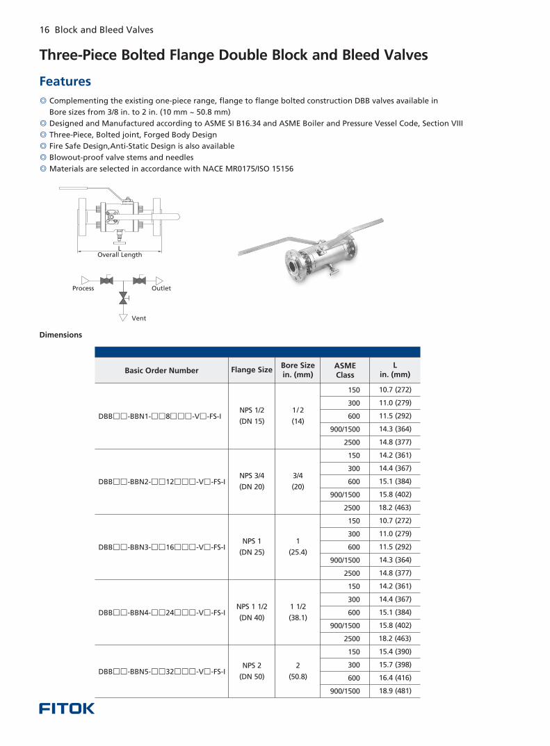
Three-Piece Bolted Flange Double Block and Bleed Valves
◎
◎
◎
◎
◎
◎
Complementing the existing one-piece range, flange to flange bolted construction DBB valves available in
Bore sizes from 3/8 in. to 2 in. (10 mm ~ 50.8 mm)
Designed and Manufactured according to ASME SI B16.34 and ASME Boiler and Pressure Vessel Code, Section VIII
Three-Piece, Bolted joint, Forged Body Design
Fire Safe Design,Anti-Static Design is also available
Blowout-proof valve stems and needles
Materials are selected in accordance with NACE MR0175/ISO 15156
Features
Dimensions
LOverall L ength
Process Outlet
Vent
NPS 1
(DN 25)
NPS 2
(DN 50)
1
(25.4)
2
(50.8)
NPS 3
(DN 80)
2
(50.8)
NPS 1 1/2
(DN 40)
1 1/2
(38.1)
Basic Order Number
NPS 1/2
(DN 15)
150
300
600
900/1500
2500
150
300
600
900/1500
2500
150
300
600
900/1500
150
300
600
900/1500
2500
150
300
600
900/1500
2500
10.7 (272)
11.0 (279)
11.5 (292)
14.3 (364)
14.8 (377)
14.2 (361)
14.4 (367)
15.1 (384)
15.8 (402)
18.2 (463)
15.4 (390)
15.7 (398)
16.4 (416)
18.9 (481)
10.7 (272)
11.0 (279)
11.5 (292)
14.3 (364)
14.8 (377)
14.2 (361)
14.4 (367)
15.1 (384)
15.8 (402)
18.2 (463)
1 2
(14)
NPS 3 4
(DN 20)
/ 3/4
(20)
DBB□□ □□ □□□ □-BBN3- 16 -V -FS-I
DBB□□ □□ □□□ □-BBN4- 24 -V -FS-I
DBB□□ □□ □□□ □-BBN5- 32 -V -FS-I
DBB□□ □□ □□□ □-BBN1- 8 -V -FS-I
DBB□□ □□ □□□ □-BBN2- 12 -V -FS-I
/
NPS 1
(DN 25)
NPS 2
(DN 50)
3/4
(20)
1 1/2
(38.1)
NPS 1 1/2
(DN 40)
1
(25.4)
NPS 1/2
(DN 15)
2500
150
300
600
900
1500
150
300
600
900/1500
2500
150
300
600
900/1500
2500
150
300
600
900/1500
150
300
600
900/1500
2500
150
300
600
900/1500
2500
11.0 (279)
11.2 (285)
11.9 (301)
14.6 (370)
15.6 (396)
14.3 (364)
14.6 (372)
15.4 (390)
16.3 (415)
18.7 (475)
15.7 (400)
16.1 (410)
16.9 (428)
17.4 (441)
19.7 (500)
10.7 (272)
11.0 (279)
11.5 (292)
14.3 (364)
14.8 (377)
10.7 (272)
11.0 (279)
11.5 (292)
14.3 (364)
14.8 (377)
14.2 (361)
14.4 (367)
15.1 (384)
15.8 (402)
18.2 (463)
3 8
(10)
NPS 3 4
(DN 20)
/
/
1 2
(14)
/
DBB□□ □□ □□□ □-BBN2- 16 -V -FS-I
DBB□□ □□ □□□ □-BBN3- 24 -V -FS-I
DBB□□ □□ □□□ □-BBN4- 32 -V -FS-I
DBB□□ □□ □□□ □-BBN- 8 -V -FS-I
DBB□□ □□ □□□ □-BBN1- 12 -V -FS-I
DBB□□ □□ □□□ □-BBN5- 48 -V -FS-I
Flange SizeASMEClass
Lin. (mm)
Bore Sizein. (mm)
Flange SizeASMEClass
Lin. (mm)
Bore Sizein. (mm)
Dimensions are for reference only and are subject to change
Basic Order Number
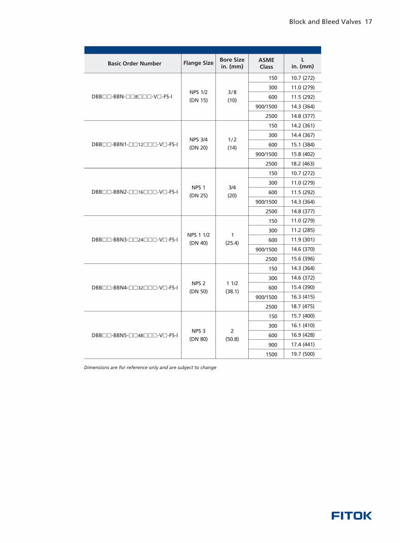
16 Block and Bleed Valves Block and Bleed Valves 17
Three-Piece Bolted Flange Double Block and Bleed Valves
◎
◎
◎
◎
◎
◎
Complementing the existing one-piece range, flange to flange bolted construction DBB valves available in
Bore sizes from 3/8 in. to 2 in. (10 mm ~ 50.8 mm)
Designed and Manufactured according to ASME SI B16.34 and ASME Boiler and Pressure Vessel Code, Section VIII
Three-Piece, Bolted joint, Forged Body Design
Fire Safe Design,Anti-Static Design is also available
Blowout-proof valve stems and needles
Materials are selected in accordance with NACE MR0175/ISO 15156
Features
Dimensions
LOverall L ength
Process Outlet
Vent
NPS 1
(DN 25)
NPS 2
(DN 50)
1
(25.4)
2
(50.8)
NPS 3
(DN 80)
2
(50.8)
NPS 1 1/2
(DN 40)
1 1/2
(38.1)
Basic Order Number
NPS 1/2
(DN 15)
150
300
600
900/1500
2500
150
300
600
900/1500
2500
150
300
600
900/1500
150
300
600
900/1500
2500
150
300
600
900/1500
2500
10.7 (272)
11.0 (279)
11.5 (292)
14.3 (364)
14.8 (377)
14.2 (361)
14.4 (367)
15.1 (384)
15.8 (402)
18.2 (463)
15.4 (390)
15.7 (398)
16.4 (416)
18.9 (481)
10.7 (272)
11.0 (279)
11.5 (292)
14.3 (364)
14.8 (377)
14.2 (361)
14.4 (367)
15.1 (384)
15.8 (402)
18.2 (463)
1 2
(14)
NPS 3 4
(DN 20)
/ 3/4
(20)
DBB□□ □□ □□□ □-BBN3- 16 -V -FS-I
DBB□□ □□ □□□ □-BBN4- 24 -V -FS-I
DBB□□ □□ □□□ □-BBN5- 32 -V -FS-I
DBB□□ □□ □□□ □-BBN1- 8 -V -FS-I
DBB□□ □□ □□□ □-BBN2- 12 -V -FS-I
/
NPS 1
(DN 25)
NPS 2
(DN 50)
3/4
(20)
1 1/2
(38.1)
NPS 1 1/2
(DN 40)
1
(25.4)
NPS 1/2
(DN 15)
2500
150
300
600
900
1500
150
300
600
900/1500
2500
150
300
600
900/1500
2500
150
300
600
900/1500
150
300
600
900/1500
2500
150
300
600
900/1500
2500
11.0 (279)
11.2 (285)
11.9 (301)
14.6 (370)
15.6 (396)
14.3 (364)
14.6 (372)
15.4 (390)
16.3 (415)
18.7 (475)
15.7 (400)
16.1 (410)
16.9 (428)
17.4 (441)
19.7 (500)
10.7 (272)
11.0 (279)
11.5 (292)
14.3 (364)
14.8 (377)
10.7 (272)
11.0 (279)
11.5 (292)
14.3 (364)
14.8 (377)
14.2 (361)
14.4 (367)
15.1 (384)
15.8 (402)
18.2 (463)
3 8
(10)
NPS 3 4
(DN 20)
/
/
1 2
(14)
/
DBB□□ □□ □□□ □-BBN2- 16 -V -FS-I
DBB□□ □□ □□□ □-BBN3- 24 -V -FS-I
DBB□□ □□ □□□ □-BBN4- 32 -V -FS-I
DBB□□ □□ □□□ □-BBN- 8 -V -FS-I
DBB□□ □□ □□□ □-BBN1- 12 -V -FS-I
DBB□□ □□ □□□ □-BBN5- 48 -V -FS-I
Flange SizeASMEClass
Lin. (mm)
Bore Sizein. (mm)
Flange SizeASMEClass
Lin. (mm)
Bore Sizein. (mm)
Dimensions are for reference only and are subject to change
Basic Order Number
18 Block and Bleed Valves Block and Bleed Valves 19
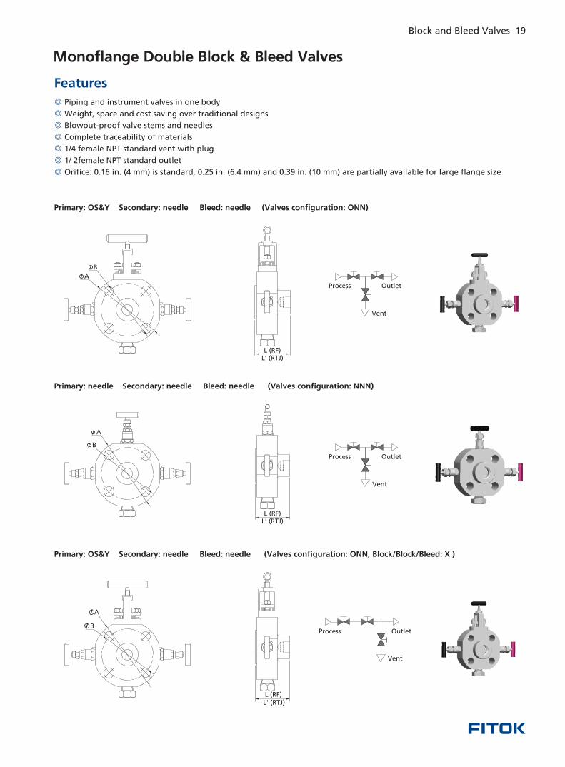
Monoflange Double Block & Bleed Valves
◎
◎
◎
◎
◎
◎
◎
Piping and instrument valves in one body
Weight, space and cost saving over traditional designs
Blowout-proof valve stems and needles
Complete traceability of materials
1/4 female NPT standard vent with plug
1/ 2female NPT standard outlet
Orifice: 0.16 in. (4 mm) is standard, 0.25 in. (6.4 mm) and 0.39 in. (10 mm) are partially available for large flange size
Features
Primary: OS&Y Secondary: needle Bleed: needle (Valves configuration: ONN)
Primary: needle Secondary: needle Bleed: needle (Valves configuration: NNN)
L (RF)L (RTJ)'
A
B
B
A
L (RF)L (RTJ)'
L (RF)L' (RTJ)
A
B
Primary: OS&Y Secondary: needle Bleed: needle (Valves configuration: ONN, Block/Block/Bleed: X )
OutletProcess
Vent
OutletProcess
Vent
OutletProcess
Vent
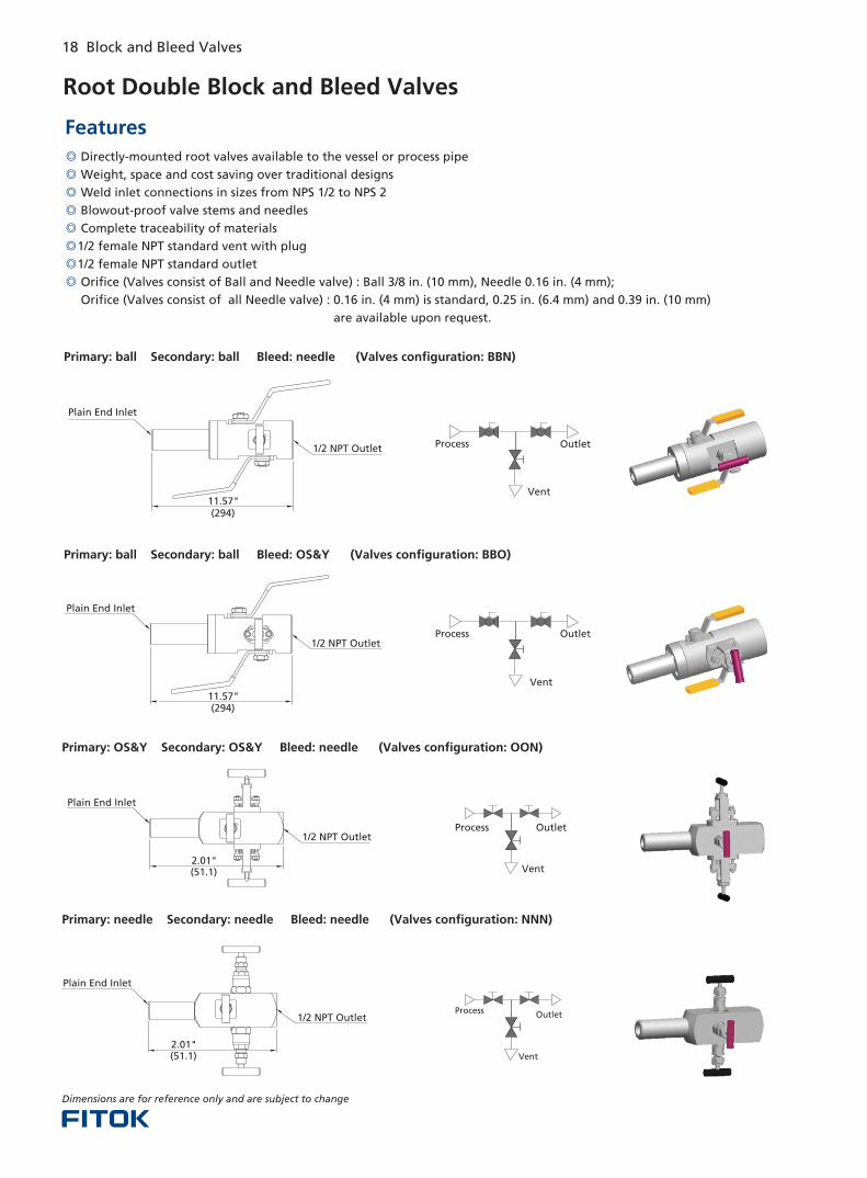
Root Double Block and Bleed Valves
◎
◎
◎
◎
◎
◎
◎
◎
Directly-mounted root valves available to the vessel or process pipe
Weight, space and cost saving over traditional designs
Weld inlet connections in sizes from NPS 1/2 to NPS 2
Blowout-proof valve stems and needles
Complete traceability of materials
1/2 female NPT standard vent with plug
1/2 female NPT standard outlet
Orifice (Valves consist of Ball and Needle valve) : Ball 3/8 in. (10 mm), Needle 0.16 in. (4 mm);
Orifice (Valves consist of all Needle valve) : 0.16 in. (4 mm) is standard, 0.25 in. (6.4 mm) and 0.39 in. (10 mm)
are available upon request.
Features
Primary: ball Secondary: ball Bleed: needle (Valves configuration: BBN)
Primary: ball Secondary: ball Bleed: OS&Y (Valves configuration: BBO)
Dimensions are for reference only and are subject to change
Primary: OS&Y Secondary: OS&Y Bleed: needle (Valves configuration: OON)
Primary: needle Secondary: needle Bleed: needle (Valves configuration: NNN)
Plain End Inlet
1/2 NPT Outlet
11.57" ( )294
Process Outlet
Vent
Process Outlet
Vent
1/2 NPT Outlet
Plain End Inlet
2.01" ( )51.1
OutletProcess
Vent
2.01" ( )51.1
Plain End Inlet
1/2 NPT Outlet OutletProcess
Vent
1/2 NPT Outlet
Plain End Inlet
11.57" ( )294
18 Block and Bleed Valves Block and Bleed Valves 19
Monoflange Double Block & Bleed Valves
◎
◎
◎
◎
◎
◎
◎
Piping and instrument valves in one body
Weight, space and cost saving over traditional designs
Blowout-proof valve stems and needles
Complete traceability of materials
1/4 female NPT standard vent with plug
1/ 2female NPT standard outlet
Orifice: 0.16 in. (4 mm) is standard, 0.25 in. (6.4 mm) and 0.39 in. (10 mm) are partially available for large flange size
Features
Primary: OS&Y Secondary: needle Bleed: needle (Valves configuration: ONN)
Primary: needle Secondary: needle Bleed: needle (Valves configuration: NNN)
L (RF)L (RTJ)'
A
B
B
A
L (RF)L (RTJ)'
L (RF)L' (RTJ)
A
B
Primary: OS&Y Secondary: needle Bleed: needle (Valves configuration: ONN, Block/Block/Bleed: X )
OutletProcess
Vent
OutletProcess
Vent
OutletProcess
Vent
Root Double Block and Bleed Valves
◎
◎
◎
◎
◎
◎
◎
◎
Directly-mounted root valves available to the vessel or process pipe
Weight, space and cost saving over traditional designs
Weld inlet connections in sizes from NPS 1/2 to NPS 2
Blowout-proof valve stems and needles
Complete traceability of materials
1/2 female NPT standard vent with plug
1/2 female NPT standard outlet
Orifice (Valves consist of Ball and Needle valve) : Ball 3/8 in. (10 mm), Needle 0.16 in. (4 mm);
Orifice (Valves consist of all Needle valve) : 0.16 in. (4 mm) is standard, 0.25 in. (6.4 mm) and 0.39 in. (10 mm)
are available upon request.
Features
Primary: ball Secondary: ball Bleed: needle (Valves configuration: BBN)
Primary: ball Secondary: ball Bleed: OS&Y (Valves configuration: BBO)
Dimensions are for reference only and are subject to change
Primary: OS&Y Secondary: OS&Y Bleed: needle (Valves configuration: OON)
Primary: needle Secondary: needle Bleed: needle (Valves configuration: NNN)
Plain End Inlet
1/2 NPT Outlet
11.57" ( )294
Process Outlet
Vent
Process Outlet
Vent
1/2 NPT Outlet
Plain End Inlet
2.01" ( )51.1
OutletProcess
Vent
2.01" ( )51.1
Plain End Inlet
1/2 NPT Outlet OutletProcess
Vent
1/2 NPT Outlet
Plain End Inlet
11.57" ( )294
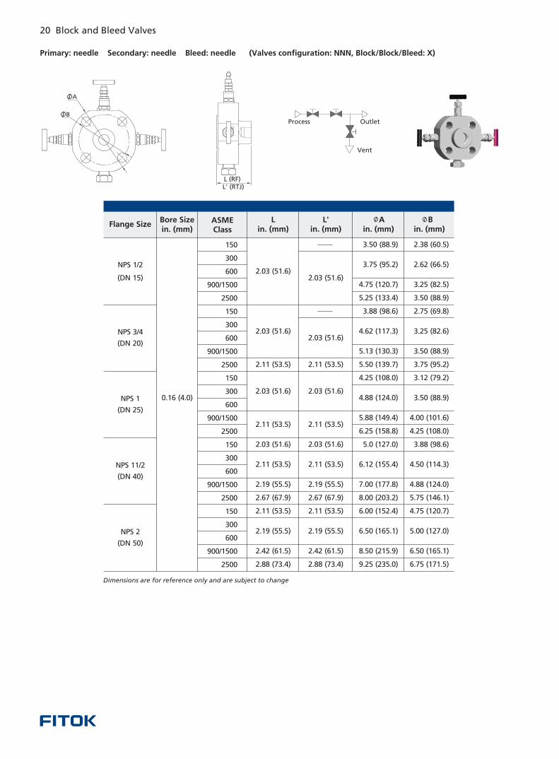
Primary: needle Secondary: needle Bleed: needle (Valves configuration: NNN, Block/Block/Bleed: X)
L (RF)L' (RTJ)
B
A
Dimensions are for reference only and are subject to change
Flange SizeBore Sizein. (mm)
ASMEClass
Lin. (mm)
L'in. (mm)
Ain. (mm)
Bin. (mm)
NPS 3/4
(DN 20)
NPS 1
(DN 25)
NPS 11/2
(DN 40)
NPS 2
(DN 50)
0.16 (4.0)
150
300
600
900/1500
2500
150
300
600
900/1500
2500
150
300
600
900/1500
2500
150
300
600
900/1500
2500
150
300
600
900/1500
2500
2.38 (60.5)
2.62 (66.5)
3.25 (82.5)
3.50 (88.9)
2.75 (69.8)
3.25 (82.6)
3.50 (88.9)
3.75 (95.2)
3.12 (79.2)
3.50 (88.9)
4.00 (101.6)
4.25 (108.0)
3.88 (98.6)
4.50 (114.3)
4.88 (124.0)
5.75 (146.1)
4.75 (120.7)
5.00 (127.0)
6.50 (165.1)
6.75 (171.5)
3.50 (88.9)
3.75 (95.2)
4.75 (120.7)
5.25 (133.4)
3.88 (98.6)
4.62 (117.3)
5.13 (130.3)
5.50 (139.7)
4.25 (108.0)
4.88 (124.0)
5.88 (149.4)
6.25 (158.8)
5.0 (127.0)
6.12 (155.4)
7.00 (177.8)
8.00 (203.2)
6.00 (152.4)
6.50 (165.1)
8.50 (215.9)
9.25 (235.0)
2.03 (51.6)
2.03 (51.6)
2.11 53.5)(
2.11 (53.5)
2.11 (53.5)
2.19 (55.5)
2.19 (55.5)
2.42 (61.5)
2.88 (73.4)
2.03 (51.6)
2.03 (51.6)
2.67 (67.9)
2.11 (53.5)
2.03 (51.6)
2.03 (51.6)
2.03 (51.6)
2.11 53.5)(
2.11 (53.5)
2.03 (51.6)
2.11 (53.5)
2.19 (55.5)
2.19 (55.5)
2.67 (67.9)
2.11 (53.5)
2.42 (61.5)
2.88 (73.4)
OutletProcess
Vent
NPS 1/2
(DN 15)
20 Block and Bleed Valves Block and Bleed Valves 21
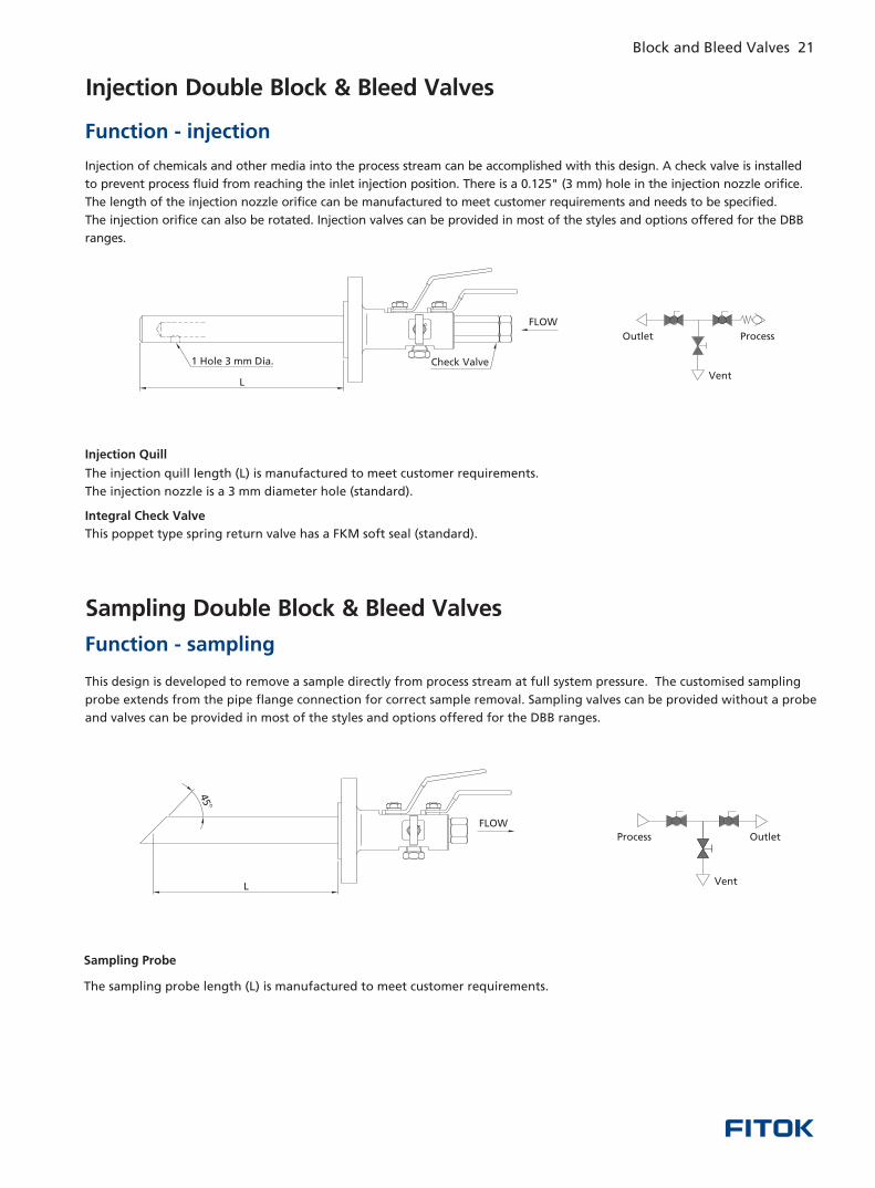
Injection Double Block & Bleed Valves
Injection of chemicals and other media into the process stream can be accomplished with this design. A check valve is installed
process fluid from reaching the inlet injection position. There is a 0.125" (3 mm) hole in the injection nozzle orifice.
The length of the injection nozzle orifice can be manufactured to meet customer requirements and needs to be specified.
The injection orifice can also be rotated. Injection valves can be provided in most of the styles and options offered for the DBB
ranges.
to prevent
Function - injection
Injection Quill
The injection quill length (L) is manufactured to meet customer requirements.
The injection nozzle is a 3 mm diameter hole (standard).
Integral Check Valve
This poppet type spring return valve has a FKM soft seal (standard).
Sampling Double Block & Bleed Valves
This design is developed to remove a sample directly from process stream at full system pressure. The customised sampling
probe extends from the pipe flange connection for correct sample removal. Sampling valves can be provided without a probe
and valves can be provided in most of the styles and options offered for the DBB ranges.
Function - sampling
Sampling Probe
The sampling probe length (L) is manufactured to meet customer requirements.
Vent
ProcessOutlet
1 Hole 3 mm Dia. Check Valve
FLOW
L
FLOW
o
45
L
Process Outlet
Vent
Primary: needle Secondary: needle Bleed: needle (Valves configuration: NNN, Block/Block/Bleed: X)
L (RF)L' (RTJ)
B
A
Dimensions are for reference only and are subject to change
Flange SizeBore Sizein. (mm)
ASMEClass
Lin. (mm)
L'in. (mm)
Ain. (mm)
Bin. (mm)
NPS 3/4
(DN 20)
NPS 1
(DN 25)
NPS 11/2
(DN 40)
NPS 2
(DN 50)
0.16 (4.0)
150
300
600
900/1500
2500
150
300
600
900/1500
2500
150
300
600
900/1500
2500
150
300
600
900/1500
2500
150
300
600
900/1500
2500
2.38 (60.5)
2.62 (66.5)
3.25 (82.5)
3.50 (88.9)
2.75 (69.8)
3.25 (82.6)
3.50 (88.9)
3.75 (95.2)
3.12 (79.2)
3.50 (88.9)
4.00 (101.6)
4.25 (108.0)
3.88 (98.6)
4.50 (114.3)
4.88 (124.0)
5.75 (146.1)
4.75 (120.7)
5.00 (127.0)
6.50 (165.1)
6.75 (171.5)
3.50 (88.9)
3.75 (95.2)
4.75 (120.7)
5.25 (133.4)
3.88 (98.6)
4.62 (117.3)
5.13 (130.3)
5.50 (139.7)
4.25 (108.0)
4.88 (124.0)
5.88 (149.4)
6.25 (158.8)
5.0 (127.0)
6.12 (155.4)
7.00 (177.8)
8.00 (203.2)
6.00 (152.4)
6.50 (165.1)
8.50 (215.9)
9.25 (235.0)
2.03 (51.6)
2.03 (51.6)
2.11 53.5)(
2.11 (53.5)
2.11 (53.5)
2.19 (55.5)
2.19 (55.5)
2.42 (61.5)
2.88 (73.4)
2.03 (51.6)
2.03 (51.6)
2.67 (67.9)
2.11 (53.5)
2.03 (51.6)
2.03 (51.6)
2.03 (51.6)
2.11 53.5)(
2.11 (53.5)
2.03 (51.6)
2.11 (53.5)
2.19 (55.5)
2.19 (55.5)
2.67 (67.9)
2.11 (53.5)
2.42 (61.5)
2.88 (73.4)
OutletProcess
Vent
NPS 1/2
(DN 15)
20 Block and Bleed Valves Block and Bleed Valves 21
Injection Double Block & Bleed Valves
Injection of chemicals and other media into the process stream can be accomplished with this design. A check valve is installed
process fluid from reaching the inlet injection position. There is a 0.125" (3 mm) hole in the injection nozzle orifice.
The length of the injection nozzle orifice can be manufactured to meet customer requirements and needs to be specified.
The injection orifice can also be rotated. Injection valves can be provided in most of the styles and options offered for the DBB
ranges.
to prevent
Function - injection
Injection Quill
The injection quill length (L) is manufactured to meet customer requirements.
The injection nozzle is a 3 mm diameter hole (standard).
Integral Check Valve
This poppet type spring return valve has a FKM soft seal (standard).
Sampling Double Block & Bleed Valves
This design is developed to remove a sample directly from process stream at full system pressure. The customised sampling
probe extends from the pipe flange connection for correct sample removal. Sampling valves can be provided without a probe
and valves can be provided in most of the styles and options offered for the DBB ranges.
Function - sampling
Sampling Probe
The sampling probe length (L) is manufactured to meet customer requirements.
Vent
ProcessOutlet
1 Hole 3 mm Dia. Check Valve
FLOW
L
FLOW
o
45
L
Process Outlet
Vent
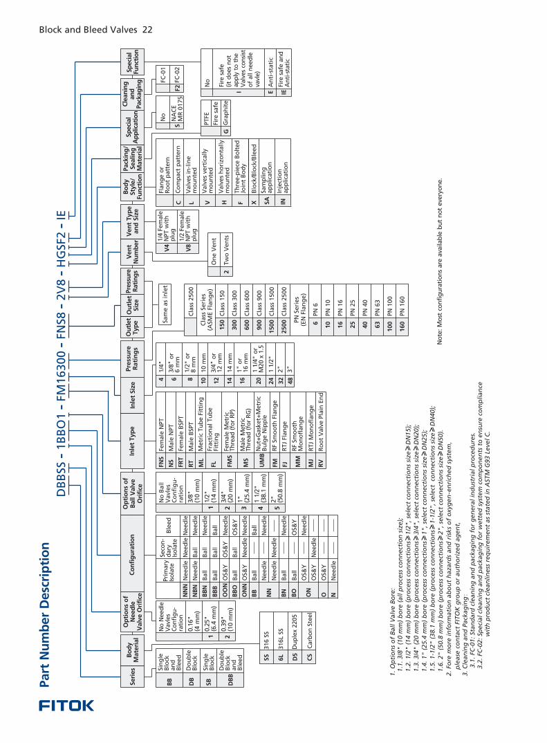
No
te:
Mo
st c
on
fig
ura
tio
ns
are
ava
ilab
le b
ut
no
t eve
ryo
ne.
1. O
pti
on
s o
f B
all V
alv
e B
ore
:
1.1
. 3/8
" (
10 m
m)
bo
re (
all p
roce
ss c
on
nect
ion
siz
e);
1.2
. 1/2
" (
14 m
m)
bo
re (
pro
cess
co
nn
ect
ion
s≥1/2
", se
lect
co
nn
ect
ion
s si
ze≥
DN
15);
1.3
. 3/4
" (
20 m
m)
bo
re (
pro
cess
co
nn
ect
ion
s≥3/4
", se
lect
co
nn
ect
ion
s si
ze≥
DN
20);
1.4
. 1" (
25.4
mm
) b
ore
(p
roce
ss c
on
nect
ion
s≥1", se
lect
co
nn
ect
ion
s si
ze≥
DN
25);
1.5
. 1-1
/2" (
38.1
mm
) b
ore
(p
roce
ss c
on
nect
ion
s≥1-1
/2",
sele
ct
con
nect
ion
s si
ze≥
DN
40);
1.6
. 2" (
50.8
mm
) b
ore
(p
roce
ss c
on
nect
ion
s≥2", se
lect
co
nn
ect
ion
s si
ze≥
DN
50).
2. Fo
re m
ore
in
form
ati
on
ab
ou
t h
aza
rds
an
d r
isks
of
oxy
gen
-en
rich
ed
sys
tem
,
p
lease
co
nta
ct F
ITO
K g
rou
p o
r au
tho
rize
d a
gen
t,3. C
lean
ing
an
d P
ack
ag
ing:
3
.1. FC
-01: St
an
dard
cle
an
ing
an
d p
ack
ag
ing
fo
r g
en
era
l in
du
stri
al
pro
ced
ure
s. 3.2
. FC
-02: Sp
eci
al cl
ean
ing
an
d p
ack
ag
ing
fo
r w
ett
ed
sys
tem
co
mp
on
en
ts t
o e
nsu
re c
om
pli
an
ce
w
ith
pro
du
ct c
lean
lin
ess
req
uir
em
en
t as
state
d i
n A
STM
G93 L
eve
l C
.
PN
10
0
PN
16
0
10
0
16
0
Pre
ssu
re
Rati
ng
s
2
F2
FC-0
1
FC-0
2S
No
NA
CE
MR
01
75
Sam
ea
sin
let
On
e V
en
t
Tw
o V
en
ts
1 2
No
Need
leV
avl
es
Co
nfi
gu
-ra
tio
n
C
lass
15
0
Cla
ss 3
00
Cla
ss 6
00
Cla
ss 9
00
Cla
ss 1
50
0
Cla
ss 2
50
0
Cla
ss S
eri
es
PN
6
PN
10
PN
16
PN
25
PN
40
PN
63
PN
Se
rie
s
No
An
ti-s
tati
c
Fire
safe
an
d
An
ti-s
tati
c
Fire
safe
(it
do
es
no
t ap
ply
to
th
e
Valv
es
con
sist
o
f all n
eed
le
vavl
e)
E IEI
Seri
es
Bo
dy
Mate
rial
Ven
t N
um
ber
Ou
tlet
Typ
eO
utl
et
Siz
eV
en
t Typ
e
an
d S
ize
Bo
dy
Sty
le/
Fun
ctio
n
Pack
ing
/Sealin
gM
ate
rial
Op
tio
ns
of
Ball V
alv
e
Ori
fice
Cle
an
ing
an
dPack
ag
ing
Sp
eci
al
Ap
plic
ati
on
Co
nfi
gu
rati
on
Inle
t Typ
eIn
let
Siz
eO
pti
on
s o
f N
eed
le
Valv
e O
rifi
ce
Sin
gle
Blo
ck
an
dB
leed
Do
ub
leB
lock
Do
ub
leB
lock
an
dB
leed
Sin
gle
Blo
ck
BB
DB
DB
B
SB
6L
SS
316L
SS
316
SS
CS
Carb
on
Ste
el
D5
Du
ple
x 2
205
Sp
eci
al
Fun
ctio
n
Need
leN
eed
leN
eed
le
Pri
mary
Iso
late
Seco
n-
dary
Is
ola
teB
leed
Need
le
Ball
Ball
OS&
Y
Ball
OS&
Y
Ball
Need
le
Need
le
Ball
Ball
OS&
Y
OS&
Y
Ball
Ball
Ball
OS&
Y
Ball
Need
le
Need
le
Need
le
Need
le
Need
le
Ball
OS&
Y
Need
le
Ball
Need
le
Need
le
OS&
Y
Need
le
NN
N
NB
N
BB
N
BB
B
OO
N
BB
O
NN
BN
BO
ON
ON
N
BB
O N
OS&
Y
Need
le
Need
le
FNS
Fem
ale
NPT
NS
FRT
RT
ML
FL MS
UM
B
FM
Male
NPT
Fem
ale
BSP
T
Male
BSP
T
Metr
ic T
ub
e F
itti
ng
Fract
ion
al
Tu
be
Fitt
ing
Fem
ale
Metr
ic
Th
read
(fo
r R
P)
Male
Metr
ic
Th
read
(fo
r R
G)
Nu
t+G
ask
et+
Metr
icB
ulg
e N
ipp
le
RF
Smo
oth
Fla
ng
e
RF
Smo
oth
M
on
ofl
an
ge
FMS
MM
RTJ
Mo
no
flan
ge
Ro
ot
Valv
e P
lain
En
d
MJ
RV
RTJ
Flan
ge
FJ
1/4
"
3/8
or
6 m
m"
1/ 2
" o
r 8
mm
10
mm
3/4
or
12
mm
"
14
mm
1 o
r 16
mm
"
1 1
/4"
or
M20
x 1
.5
2"
1 1
/2"
6
10
16
25
40
63
15
0
30
0
60
0
90
0
15
00
25
00
1/4
Fem
ale
NPT
wit
h
plu
g
V8
1/2
Fem
ale
NPT
wit
h
plu
g
V4
Flan
ge
or
Ro
ot
patt
ern
C L V F X
Co
mp
act
patt
ern
Valv
es
in-l
ine
mo
un
ted
Th
ree-p
iece
Bo
lted
Jo
int
Bo
dy
Blo
ck/B
lock
/Ble
ed
Valv
es
vert
ically
mo
un
ted
SA
Sam
plin
g
ap
plica
tio
n
INIn
ject
ion
ap
plica
tio
n
Valv
es
ho
rizo
nta
lly
mo
un
ted
H
PTFE
GG
rap
hit
e
Pre
ssu
re
Rati
ng
s
Fire
safe
(4 m
m)
0.1
6"
0.2
5"
(6.4
mm
)
(10
mm
)0.3
9"
1 2
3/8
"(1
0 m
m)
1/2
"(1
4 m
m)
3/4
"(2
0 m
m)
3 4
1"
(25.4
mm
)
38.1
mm
)1 1
/2"
( 5
(50.8
mm
)2"
No
Va
vle
sC
on
fig
u-
rati
on
Ba
ll
4 6 8
10
12
14
16
20
24
32
48
3"
DB
BSS
1B
BO
1 F
M16300
FN
S82V
8SF
2 -
- -
-
HG
-
- I
E
Part
Nu
mb
er
Desc
rip
tio
nBlock and Bleed Valves 22
Cla
ss 2
50
0
(ASM
E F
lan
ge
)
(EN
Fla
ng
e)
Block and Bleed ValvesBB, DB, SB and DBB Series
www.fitokgroup.com
FK-IC-GV-13-EN-160129
FITOK GroupFITOK GmbH (Headquarter)Sprendlinger Landstr. 115, 63069 Offenbach am Main, GermanyTel.: +49 69 8900 4498 Fax: +49 69 8900 4495
FITOK, Inc.13843 North Promenade Blvd., Suite 750, Stafford, Texas 77477, USATel.: +1 281 888 0077 Fax: +1 281 582 4051
FITOK Incorporated1-4F, Block C, Zone E, Yingtailong lndustrial Park, Dalang Street, Longhua District, Shenzhen, 518109, ChinaTel.: +86 755 2803 2500 Fax: +86 755 2803 2619
FITOK Middle East Oil Equipment Trading LLC208-209, Makateb Tower, Airport Road, P.O.Box 185412, Deira, Dubai, UAETel.: +971 4 2959 853 Fax: +971 4 2959 854