bayard-alpert ionization gauges
DESCRIPTION
Technical NoteTRANSCRIPT
www.thinkSRS.com 1
(408)744-9040 Stanford Research Systems www.thinkSRS.com
Bayard-Alpert Ionization Gauges
This application note attempts to explain the principles of operation of the Bayard-Alpert Ionization Gauge, or BAG, outline its fundamental limitations and describe the ion gauge types that have successfully surmounted some of them. A few practical tips are also provided along the way. The emphasis has been placed on gauges that are commercially available.
In This Application Note Principle of Operation 3
Introduction 3 Gauge Principles 3 Gauge Sensitivity 4
Definition 4 Pressure Dependence 6 Gas Dependence 7 Electrode Geometry Dependence 9 Bias Voltage and Emission Current Dependence 11 Gauge Envelope Dependence 12 Temperature Dependence 14 Magnetic Field Dependence 14 History Dependence 15
Limiting Factors for Low Pressure Operation 17 X-ray Limit 17
Gauge design 18 Electrode Surface conditions 19 Emission Current 19 Envelope Bias (Forward vs. Reverse X-ray Effect) 19
Electron-Stimulated Desorption (ESD) 20 Leakage Currents 21 Outgassing 21 Gauge Pumping 22 Filament reactions and outgassing 24 Gas Permeation 24
Mechanical Construction 25 Glass tubulated gauges 25 Nude gauges 28 High-accuracy gauges 31 Tiny Gauges 32
Filament Considerations 34 Filament Materials 34 Filament Reactions 36 Emission of ions and neutrals 37
Accuracy and Stability 38 Reproducibility 38 Stability 38
Degassing 41 Safety and Health Considerations 43
Electric Shock 43 Thoria Alpha Emission 43 Glass breakage 43 Burns 43 X-rays 44
References 45

2 Bayard-Alpert Ionization Gauges
Stanford Research Systems (408)744-9040 www.thinkSRS.com
Principle of Operation 3
(408)744-9040 Stanford Research Systems www.thinkSRS.com
Principle of Operation
Introduction The Bayard-Alpert ionization gauge (BAG) was first described in 19501. Modern versions of the gauge have preserved most of the basic elements of its original implementation. Standardization of the BAG design has made it possible for vacuum equipment manufacturers to produce generic ion gauge controllers, such as the IGC100, capable of controlling BAGs from many different manufacturers.
BAGs are not perfect, and the user who believes their pressure indications without a basic understanding of their operation is likely to be fooled.
This application note attempts to explain the principles of operation of the BAG, outline its fundamental limitations and describe the ion gauge types that have successfully surmounted some of them. A few practical tips are also provided along the way. The emphasis has been placed on gauges that are commercially available.
Since it is not possible to cover this complex gauge in a short note, a comprehensive list of references is provided at the end that should allow the reader to find answers to most problems.
Gauge Principles Figure A-1 describes a prototypical BAG design. Electrons boil from the hot filament (30Vdc) and are accelerated towards the anode grid (180Vdc). As the current (0.1-10 mA typical) of highly energetic (150eV) electrons traverse the inner volume of the grid cage, they ionize some of the gas molecules they encounter in their path. Electrons that do not encounter any obstacles in their path, exit the grid and are immediately directed back into its inner volume by the electrostatic field, resulting in a multiple-pass ionization path that ultimately ends by collision with a grid wire. The ions formed inside the anode grid are efficiently collected by the grounded (0Vdc) collector wire that is located along the axis of the cylindrical grid and connected to the controller’s electrometer. If the electron emission current and the temperature of the gas are constant, then the ion current is proportional to the number density and the pressure of the gas. The positive ion current provides an indirect measurement of the gas pressure.

4 Principle of Operation
Stanford Research Systems (408)744-9040 www.thinkSRS.com
Figure A-1. Typical Bayard-Alpert configuration (glass-tubulated design)
Gauge Sensitivity
Definition The number of ions formed inside the anode grid, and therefore the current measured by the electrometer of Figure A-1, is a function of
• the number of molecules per unit volume • the ionization cross section for the particular gas at the specified electron energy • the arrival rate of the electrons (i.e. emission current) • the path length of the electrons.
A simple ionization gauge equation, based on very simple assumptions2, that connects these quantities is derived below and used to define a sensitivity factor for the BAG.
Let σi be the ionization cross section for a gas molecule, L the length of the ionizing space, and A the cross-sectional area of the electron beam. The number of molecules included in this volume is n·L·A, where n is the molecular density, related to the gas pressure by n = P/(k·T). The collective ionization cross area of the molecules contained in this volume is Aσ = (n·L·A) ·σi = σi·L·A·P/(k·T) and the fraction of incoming electrons

Principle of Operation 5
(408)744-9040 Stanford Research Systems www.thinkSRS.com
that participate in ionizing collisions is Aσ / A = n·L·σi = σi·L·P/(k·T). Let N be the number of electrons entering the anode grid cage per unit time. The number of ionizing collisions per unit time is then N·σi·L·P/(k·T) and, assuming all ions are effectively collected, the corresponding collector current Ic measured by the electrometer can then be expressed as:
Ic = σi·L·[P/(k·T)]·N·e (eqn.1)
where e is the electron charge.
Substituting the electron emission current Ie = N·e into eqn. 1 leads to the expression
Ic = [σi·L/(k·T)]·Ie·P (eqn. 2)
The factor [σi·L/(k·T)] is a function of (1) the gas type (σi), (2) the geometry of the gauge (L), and (3) the absolute temperature (T), and is generally defined as the gauge sensitivity factor, or S. Substituting this sensitivity factor into eqn. 2 leads to the standard ionization gauge equation
Ic = S·Ie·P (eqn. 3)
And rearranging terms leads to the well-known expression for the gauge sensitivity factor
Sensitivity = (Ion Current) / [(Electron Current)·( Pressure)] (eqn. 4)
This definition assumes a linear relationship between the pressure, the ion current and the electron emission current, and provides a proportionality constant independent of the electron current and dependent only on gas species, gauge geometry and operating temperature. As defined, the sensitivity factor has units of reciprocal pressure (i.e. Torr-1).
Some gauge manufacturers prefer to use the term gauge constant or gauge coefficient for S. Then sensitivity can be reserved for the product S·Ie, which is also an important parameter for the gauge.
Knowing the sensitivity factor Sg for a gas g, and assuming the electron emission current is also available, the total pressure for the pure gas can be easily calculated from the collector current using the following equation
P = Ic / (Sg·Ie) (eqn. 5)
A nominal sensitivity factor for nitrogen is usually provided by the gauge manufacturer. This value should not be relied upon for accurate work since the precise values will vary significantly between seemingly identical gauges and even more between different gauge types, filament materials and operating potentials. Typical nitrogen sensitivity factors for commercially available BAGs fall in the range of 8 to 45 Torr-1. Several aging mechanisms are also responsible for changes in gauge sensitivity with time, affecting the long term stability and reproducibility of BAG pressure readings.
6 Principle of Operation
Stanford Research Systems (408)744-9040 www.thinkSRS.com
IMPORTANT! The only truly reliable method of determining a BAG sensitivity factor is through direct and careful calibration.
The electron emission current of many modern ion gauge controllers, including the IGC100, is fully adjustable and generally available to the user.
The sensitivity of a BAG, and the reliability of its measurements, is affected by several different variables. Some of these variables may be beyond operator control, or are controllable only with significant effort. Attempts to calculate sensitivity factors for BAGs, based on ionization efficiencies and geometrical considerations, have not proven useful because of a number of ill-defined parameters such as temperature, field distribution and ion collection efficiency. The effects of some of the variables are readily quantified, others are not, and only the magnitude of potential errors can be indicated.
The following sections cover some of the variables that can significantly affect the sensitivity of BAGs.
Pressure Dependence A strict linear relationship between the pressure and the ion current makes the BAG the most accurate continuous indicator of total pressure in high vacuum applications.
The upper limit of BAG operation is about 10-3 Torr for most gauge designs, and is defined as the pressure at which the ion current vs. pressure relationship deviates from linearity. Specification claims beyond this range must be approached with caution!
The exact pressure value at which a BAG deviates from linearity differs significantly between gauge types and is a function of the electron emission current setting, Ie. In general, a reduction of the electron emission current results in an extension of the linearity range, and it is generally agreed that Ie must be kept at the lowest practical value (certainly no more than 0.1 mA) for all work at and above 10-3 Torr. Some commercially available ion gauge controllers are programmed to automatically reduce the electron emission current to 0.1 mA, or less, as the pressure approaches this upper limit. This approach is only adequate for moderately accurate measurements since, as described later, the sensitivity factor is dependent on the electron current3 at these higher pressures and that effect is generally not accounted for in those controllers. A more accurate approach (available on the IGC100) that does not rely on linear behavior of the sensitivity, and has been shown to effectively extend the usable range of conventional BAGs into the 10-2 Torr range, involves the use of fixed low electron emission currents (0.1 mA typical) and the calculation of pressure values from a gauge calibration curve (P vs. Ic) stored in the controller’s memory.
An interesting trick to extend the high-pressure operation of a conventional BAG and implemented in at least one commercially available controller, is given in a patent by Paitich and Briglia4 describing a method of measuring pressure up to 1 Torr by modulating the anode grid voltage and using a non-linear amplifier. This method is not recommended if moderate accuracy is required at the higher pressures where capacitance manometers are a much better choice. Thoria coated filaments are the only option at these high pressures.
Principle of Operation 7
(408)744-9040 Stanford Research Systems www.thinkSRS.com
Non-linearity at the high end of the pressure scale is caused by several effects5. Increased positive ion density and multiple non-elastic collisions with neutral molecules (due to the reduced mean free path) can alter the path6 and energy of the electron beam and also force some of the newly formed ions out of the anode grid without a chance of being captured by the collector. As the pressure increases, the secondary electrons and ions produced by ionization become a significant fraction of the electron stream. These secondary electrons do not contribute to ionization but are part of the electron emission current. These effects were thoroughly investigated by Schultz and Phelps and the reader is referred to their publications for further information7.
Various attempts have been made to extend the range of BAGs8, but very few have been commercial successes. One such commercial design, available under several different trade names9, uses a narrow grid (12mm diameter x 46mm long), a thoria-coated filament, and a grounded platinum coating on the inside of the 41mm diameter glass tube. These broad-range glass tubulated gauges are designed to operate all the way up to 10-1 Torr (with 0.01 mA emission current above 10-3 Torr) while still providing a sensitivity factor of 8 Torr-1. However, they have been shown to be susceptible to large time-dependent instabilities and non-linearities10. A miniaturized, all-metal ionization gauge that retains the traditional design, operating voltages, good sensitivity and low X-ray limit of the conventional BAG has recently become commercially available11. This tiny gauge (5% of the conventional volume) utilizes a dual collector design to increase ion collection efficiency (20 Torr-1 typical) while at the same time providing a wider usable pressure range that extends from 3x10⁻¹⁰ to 5x10⁻² Torr. Tiny gauges are a modern alternative to glass tubulated gauges and will likely become relatively more important in the future.
Note The IGC100 controller is compatible with most commercially available BAG designs including: Glass-tubulated, Nude, Nude-UHV, STABIL-ION® (Granville-Phillips, Helix Corporation), and MICRO-ION® (Granville-Phillips, Helix Corporation). Default setup files are stored in the controller’s memory to facilitate configuration of the instrument for operation with any of these gauges.
As the total pressure is decreased below ≈10-4 Torr, the gauge sensitivity factor is expected to become pressure independent. For most common gases encountered in high vacuum applications, this behavior has been confirmed experimentally for total pressures down to 10-9 Torr 12. Consequently, in all cases (including the IGC100 controller), pressure measurements with a BAG in the UHV region below 10-7 Torr are based on linear extrapolation of gauge response determined at higher pressures.
Gas Dependence BAG sensitivity depends upon the gas composition.
For electrons to produce ionization of gas molecules by bombardment, they must have a certain minimum kinetic energy. This minimum energy is called the ionization potential and is different for every type of molecule. Above the threshold energy, the ionization efficiency increases linearly with the electron energy until a maximum is reached. For most molecules, this maximum occurs between 50 and 150 eV. For electron energies above the maximum, the ionization efficiency slowly decreases with electron energy.

8 Principle of Operation
Stanford Research Systems (408)744-9040 www.thinkSRS.com
Plots of ionization efficiency vs. incident electron energy can be obtained from the careful data of Smith and Tate13. Their results show that ionization cross sections, σi, of common gases differ by almost a decade at the electron energies of 150 eV that are typical in BAGs. Furthermore, the relative ionization efficiencies Rσ - the ratio of the ionization efficiency for a given gas to the ionization efficiency for a standard gas (usually nitrogen) - is a function of electron energy.
Since the BAG sensitivity for a specific gas is directly related to the value of the ionization cross section of the corresponding gas molecules (eqn. 2), the sensitivity factor Sg, supplied by the gauge manufacturer, is only valid for the gas for which it is specified and the pressure readout of the controller provides a direct reading only for that specific gas. The standard gas, used by the entire industry for gauge specification, is nitrogen and, unless correction factors are applied, all readings are considered to be nitrogen-equivalent pressures.
The sensitivity of a generic BAG to some of the most common gases encountered in a high vacuum environment follows the order: He < Ne < D2 < H2 < N2 ≈ Air < O2 < CO < H2O < NO < Ar < CO2 < Kr < Xe. Nominal relative sensitivity factors, Rg, to convert nitrogen-equivalent readings into direct pressure readouts for gases other than nitrogen, are available from all gauge manufacturers and from the general vacuum literature14. For gases where little or no data are available, it has been shown that a reasonable approximation to the relative sensitivity factor Rg can be obtained from the ratio of ionization cross sections for those gases at 150 eV of electron collisional energy. Several ionization cross section tables are available in the scientific literature15.
Once the relative sensitivity factor is known, direct pressure readings are calculated from the straightforward mathematical equation
P = [Ic/(Sg·Ie)] where Sg = SN2·Rg (eqn. 6)
Nominal relative sensitivity factors cannot be relied upon for accurate measurements since they are known to vary significantly between seemingly identical gauges and even more for different gauge types, filament materials, and operating potentials. For general vacuum use, the discrepancy in reported measurements is not greater than 10% for the common gases rising to a little above 20% for the less common gases where less accurate information is available. Relative sensitivities are pressure dependent and become particularly unreliable above 10-5 Torr16. Where greater precision is required, gauges must be calibrated individually against the specific gases and under conditions as near as possible to the operating conditions of the vacuum system.
Note The IGC100 controller uses a nitrogen sensitivity factor, SN2, and a single relative sensitivity factor Rg (labeled 'gas correction factor') for every BAG connected to its back panel. The two parameters are automatically applied to the calculation of pressures when N2 Sense Factor is used as the pressure calibration source.
Note The nominal gas correction factors, used by most high vacuum practitioners to correct their 'nitrogen-equivalent' pressure readings for other common gases, can be found in the application note, 'Gas Correction Factors for Bayard-Alpert Ionization Gauge Readings'.

Principle of Operation 9
(408)744-9040 Stanford Research Systems www.thinkSRS.com
Electrode Geometry Dependence Many design parameters affect the probability of creating and collecting ions in a BAG, and thus the value of the sensitivity. This section focuses on the effects that electrode geometry have on BAG sensitivity. Important geometrical factors include
• filament to grid spacing • collector wire location and diameter • anode grid end closures • grid diameter
To the extent that any of these parameters change with time of operation, or differ from gauge to gauge, the sensitivity will change or be different gauge-to-gauge.
The sensitivity of a 'conventional' BAG (available from almost any gauge supplier) with 22 mm diameter anode grid x 45 mm length, with filament to grid spacing of 6 mm and collector wire 0.25 mm diameter, is nominally 10 Torr-1. Adding grid end closures roughly doubles this. Increasing the collector wire diameter to 1 mm adds another factor of two to the sensitivity and extends the high-pressure range.
The effect of grid-filament spacing on sensitivity has received considerable attention. Redhead17 was the first researcher to illustrate the significance of the precise positioning and biasing of the filament. More recently, Bills18 utilized computer simulations to demonstrate and prove that filament position displacements as small as 1 mm can significantly affect the electron trajectories within the anode volume. Any change in electron trajectories will automatically affect the sensitivity of a BAG. Sources for grid-filament spacing variations are (1) relaxed manufacturing tolerances resulting in significant gauge-to-gauge variations, (2) changes in filament position and/or shape due to rough handling (i.e. mounting accidents in nude gauges), (3) changes in filament position and/or shape due to thermal cycling.
Some investigators19 have obtained results suggesting that gauges with tungsten filaments provide better stability than do gauges with thoria coated filaments. The current belief is it is not the filament material that causes the improvement, but rather the shape of the cathode. Tungsten cathodes are typically made as tight springs stretched between rigid posts that tend to move relatively little during long term use as compared to the hairpin shaped or relatively unsupported ribbon shaped thoria coated cathodes. BAGs with spring-tensioned filament assemblies have recently become commercially available and should be considered if long term accuracy and stability are a concern20.
The preferred mounting orientation is with the filament and anode grid in a vertical position to minimize electrode distortion caused by gravity pull and thermal cycles. Whenever possible, choose the gauge with the strongest electrode-support posts.
Note Spring tensioned filament assemblies are standard in all Bayard-Alpert gauges purchased directly from Stanford Research Systems.
The ion collection efficiency of an ionization gauge is affected by the diameter of the collector wire. This effect has been extensively studied and discussed in the vacuum literature21. The 'conventional' BAG has a 0.25 mm diameter ion collector wire. This
10 Principle of Operation
Stanford Research Systems (408)744-9040 www.thinkSRS.com
small diameter is required to extend the low pressure operating limit of the BAG into the 10-10 Torr range as described later. Many ions have too much angular momentum to be collected by the small diameter wire. Ions that are not collected on their first pass at the ion collector continue to orbit until they strike a low potential surface such as the cathode or gauge envelope22. Thus, it is likely that a space charge cloud of orbiting ions surrounds the collector and is susceptible to small changes in geometry or local potentials. Any variation in this space charge affects electron trajectories and thus the sensitivity. This space charge effect becomes more noticeable with increases in either pressure or emission current. It is not unusual to detect drops in BAG sensitivity factors as the emission current is increased from 1 to 10 mA at pressures as low as 10-6 Torr23. In fact, in gauges with very fine (< 0.1 mm) wires, sensitivity decreases can be observed as early as 10-8 Torr24.
It is generally accepted that there is no advantage to using collector wires with a diameter smaller than 0.125 mm (as typically found in nude BAGs for UHV applications). High accuracy BAGs with a 1 mm diameter ion collector have recently become commercially available25. The thicker wire provides increased mechanical stability, a higher overall sensitivity (as a result of the more efficient capture of high angular momentum ions) and an extended upper limit range extending to 10-2 Torr for 0.1 mA electron emission current. The extended upper range is due to the reduced space charge around the collector that results from the more efficient ion collection. These improvements are achieved with no significant compromise at the low pressure end, which still remains at 1.6x10⁻¹⁰ Torr for 4 mA of emission current.
Until recently, few gauge manufacturers have made an effort to produce electrode structures with sufficiently close tolerances. It is not unusual to see gauges where the center collector is curved, not coaxial with the anode grid, or is at an angle with respect to the anode’s axis. In some gauges, a slight lateral force on the collector feedthru, such as might be caused by the collector wire, can visibly change the position of the collector. As demonstrated by Bills26, a 2 mm displacement of the collector wire from the axis is enough to show changes in electron trajectories and sensitivity. High accuracy gauges manufactured to very tight mechanical tolerances are now commercially available and should be carefully considered if gauge-to-gauge reproducibility and long term stability are important. Whenever possible, mount the BAG in a vertical position, with the collector pin pointing down, to avoid electrode shape distortions by gravity pull.
Conventional BAGs traditionally include wire helix anode grid structures with open ends. A popular double-helix design allows for safe resistive heating of the electrode assembly during degas, and also provides a fairly robust structure. Nude ultrahigh vacuum gauges usually include a more delicate (i.e. very fine wire) 'squirrel-cage' anode grid design with closed ends. Nottingham27 was the first to report the addition of grid end closures to the BAG to prevent the escape of uncaptured ions from the open ends of the cylindrical grid, thereby increasing the sensitivity of the gauge and extending the low pressure limit into the 10-11 Torr range. As a rule-of-thumb, adding grid end closures roughly doubles the sensitivity factor of a BAG. A typical UHV nude BAG has a specified sensitivity factor of 25 Torr-1 for 4 mA of electron emission current. However, as demonstrated by Peacock and Peacock28, the sensitivity of gauges with grid end closures declines sharply above 10-5 Torr when operating at an emission current of 1 mA. With open grids, the sensitivity remains constant up to 10-3 Torr under identical operating conditions. The origin of this effect is poorly understood, but it is most likely caused by the relative increase in space charge from the non-collectable ions that accumulate inside the enclosed grid volume29.

Principle of Operation 11
(408)744-9040 Stanford Research Systems www.thinkSRS.com
As mentioned before, the high pressure limit of UHV BAGs with closed grids can be extended operating at an emission current of ≤0.1 mA.
Most commercially available BAGs are manufactured with 22 mm diameter x 45 mm long anode grid cages. A narrow grid design, 12 mm diameter, can be found in broad-range ionization BAGs that extend the operating limit into the 10-1 Torr range. The larger length-to-diameter ratio is designed to minimize axial drift of ions out of the collector region. An internal conductive coating is used in these glass tubulated gauges to control the electrostatic environment and maximize electron ionization paths. Performance characteristics for these gauges have been published in the vacuum literature, and the reader should consult the references for further information30.
Bias Voltage and Emission Current Dependence A survey of the specifications for all commercially available BAGs quickly reveals that they all share the same electrode potential requirements
• collector potential of 0 Vdc • filament bias of +30 Vdc • anode grid bias +150-180 Vdc • shield potential 0 Vdc.
Manufacturer recommended electrode emission currents are usually 10 mA for conventional BAGs (10 Torr-1) and 4 mA for UHV nude BAGs (25 Torr-1).
Changes in electrode potentials cause shifts in sensitivity31. As may be expected, the collector current is a complex function of the electrode potentials because both the electron trajectories and ionization efficiencies depend on these voltages.
The positive (+30 Vdc) filament bias assures that all electrons emitted from the filament stay away from the relatively negative (0 Vdc) ion collector32. Any increase in collector voltage results in a decrease in the ion current because of the decreased electron penetration (i.e. reduced pathlength) of electrons into the anode grid space and the reduction in electron energy. Sensitivity differences up to 2% have been observed when the cathode bias was applied to the top rather than bottom of the filament.
The filament-to-anode voltage determines the collisional energy of the electrons that traverse the inner volume of the grid cage. The electron energy is simply calculated, in eV, as the difference in bias voltage between the anode grid and the filament. The electron energy for the prototypical ion gauge controller is 150 eV. If the collector current is measured for varying grid potentials, at a fixed pressure (above 10-7 Torr), filament bias and electron current, the curve showing Ic vs. Vg follows the expected characteristic shape of gas ionization probability vs. electron impact energy - Ic rises rapidly with Vg up to 200 V and varies slowly with grid voltages above this value33.
As a rule of thumb, the sensitivity of an ion gauge is observed to change 0.1%/V and 1%/V for filament-to-grid and filament-to-ground voltage variations, respectively. Broad-range BAGs have been reported to exhibit the largest sensitivities to electrode bias variations of all current designs34. Most BAGs are so non-stable and so non-reproducible for other causes that the relatively minor effects of variations in potentials applied by

12 Principle of Operation
Stanford Research Systems (408)744-9040 www.thinkSRS.com
traditional controllers35 have been generally ignored. However, with the recent introduction of high-accuracy (and highly stable) BAGs, the need for accurate and reproducible electronic control of the biasing voltages has been finally established.
The sensitivity factor of a BAG is a function of the emission current36. Changing the emission current from 0.1 to 1 mA usually causes no significant changes in nitrogen sensitivity, but increasing it to 10 mA can decrease the sensitivity factor by more than 20% and cause marked high pressure non-linearities above 10-5 Torr. The extent of this effect is highly dependent on gauge geometry. In general, a reduction of the electron emission current results in an extension of the linearity range, and it is generally agreed that Ie must be kept at the lowest practical value (certainly no more than 0.1 mA) for all work at and above 10-3 Torr.
Sensitivity differences of several percent have been observed at the same filament heating power, emission current and pressure when AC rather than DC power is used. Changes in the duty cycle of the AC power also cause observable changes in sensitivity37.
The recommended operating procedure from the Vacuum Group of the National Institute of Standards includes
• Operate all BAGs with 1 mA, or less, emission current . The only reason to operate a modern gauge with 10 mA of emission is to increase the temperature of the gauge and speed outgassing.
• The linearity of BAG response is also improved if a noise free, direct-current filament current supply is used (such as in the IGC100 controller).
A quality ionization gauge controller designed for high accuracy measurements (such as the IGC100) must control biasing voltages to within a few volts directly at the gauge head38 and emission currents39 to within a few percent.
Note In conventional controller designs, the filament bias voltage is measured and controlled inside the box. As a result, the filament bias can vary with heating current because of the resistive voltage drop across the cable. This voltage drop may be substantial when using long cables and typical heating currents (between 3 and 10 amps). This variability is of no consequence for conventional (nude or glass) BAGs because these minute instabilities are overwhelmed by much larger effects. However, controlling filament bias at the controller is inadequate for measurements with modern high-accuracy gauges. In the IGC100, the filament bias voltage is measured at the gauge head, and hence, electrode potentials are independent of cable length40.
Gauge Envelope Dependence Several researchers have shown that the sensitivity of a BAG assembly can be influenced significantly by the relative positioning and electrical potential of the gauge envelope41.
In a glass tubulated gauge, the inner insulating surfaces of the glass tube can change potential abruptly due to the accumulation of electrical charge, causing sudden shifts in pressure indication unrelated to any gas density variation. The effect was first described and explained by Carter and Leck42 as early as 1959, and analyzed by Redhead43 and

Principle of Operation 13
(408)744-9040 Stanford Research Systems www.thinkSRS.com
Pittaway44 based on the dependence of electron paths on changing electrical boundary conditions. As a conductive film builds up on these surfaces with time of use, sudden mode shifts tend to occur less frequently and eventually disappear. This gradual change in potential affects the long-term stability of glass tubulated ion gauges. Keep in mind that exposed insulators in nude gauges may cause similar effects if conductive films deposit on them.
Several glass BAGs utilize a platinum conductive thin-coating on the inner glass wall to help stabilize the wall potential. The shield potential is either electrically grounded through a separate connection pin, or internally connected to the filament return electrode. Tilford, McCulloh and Woong45 demonstrated the effect of these coatings and observed that when the shield of one gauge, normally held at ground potential, was allowed to float up to filament potential, the collector current increased by 23%. Abbott and Looney46 performed a detailed study of the influence of inner potential on the sensitivity of platinum-coated glass gauges and found that the shield potential depended on pressure and also on the details of the filament potential waveform provided by the gauge controller. They concluded that sensitivity non-linearities in those gauges could be minimized by holding the inner surface to a fixed direct current potential or by using a controller (such as the IGC100) that provides a noise-free filament heating DC current.
Note These effects are not commonly considered by the users of glass ionization gauges because very often the gauge envelope is an integral part of the gauge structure (i.e. glass tubulated gauges) and the dimensions and relative spacing of the envelope and electrode assembly cannot be altered by the user. The potential of the glass wall also influences the residual current produced as a result of the reverse X-ray effect described later in this application note.
The sensitivity value of a nude gauge is dependent on the way it is mounted on the system. This is not new knowledge, but there is no widespread appreciation of the effect among current users of nude gauges. Filippelli47 investigated the influence of envelope size and shape on the nitrogen sensitivity of conventional nude BAGs. His report shows that changes in gauge envelope can result in measurement errors as large as 50% with some BAGs. Thus, the envelope must be considered a proper part of an ionization gauge, and a specification of nude gauge sensitivity is not complete unless the geometry and potential of its envelope are also given. It is common practice to calibrate and operate nude ion gauges inside a nipple 38 mm ID x 100 mm long, with a screen at the input port.
Modern high accuracy gauges rely on heavy shielding to (1) protect the electrode structure from external or uncontrollable fields, (2) better define charged particle trajectories and (3) improve gauge-to-gauge reproducibility and long term stability. In a commercially available design48, the entire electrode assembly, is housed inside a grounded metal envelope. This envelope completely surrounds the anode-filament-collector structure to help provide a stable electrical environment for charged particle trajectories. A grounded, perforated, high conductance shield over the port helps to electrically isolate the transducer from the remaining of the vacuum system, and grounded conducting shield between anode and the feedthrus prevents the ceramic insulators from becoming contaminated and charged.
14 Principle of Operation
Stanford Research Systems (408)744-9040 www.thinkSRS.com
Temperature Dependence For most room temperature measurements the effects of ambient temperature variations on BAG readings are insignificant.
Studies of this effect have generally shown that it is not as large as would be predicted from theoretical considerations accounting for both density and thermal transpiration effects, i.e. the sensitivity varying inversely with the square root of the absolute temperature of the gas inside the gauge49.
Determining the gas temperature is a difficult task in a tubulated BAG. It is probably accurate to say that most of the molecules equilibrate with the envelope, but the envelope temperature is not symmetric because of the asymmetric location of the filament. The envelope (glass or metal) of a BAG is usually at a temperature much higher than ambient as determined by the power (10 W) radiated by the hot filament and absorbed by the envelope’s walls. For example, some metal encapsulated gauges are actually provided with vented guards to protect users against burns. The absorption of energy from the filament by the envelope increases with age as the walls get progressively darker due to contamination. Variations in filament work-function and emissivity due to aging, contamination or chemical reaction with the gas will result in changes in filament and envelope temperature that might require correction for accurate measurements. Bills, Borenstein and Arnold50 suggested a pressure calculation procedure that includes the filament heating power as a parameter, increasing gauge-to-gauge reproducibility and long term stability.
Haefer51 did find a correlation with the square root of the temperature of the flange of a nude BAG mounted in an enclosure. Close, Lane and Yarwood52 found the ion current to change 0.075%/K, approximately half what one would expect from the envelope temperature of a BAG. If a BAG is not used under the same temperature conditions as those during its calibration, a correction might be required in high accuracy measurements53.
There is always a delay between turning on a BAG and obtaining a reliable reading. It is necessary to wait for thermal equilibrium of the gauge54 and its surroundings (not that easy under vacuum).
Magnetic Field Dependence Magnetic fields have a strong and rather unpredictable effect on gauge sensitivity by changing the trajectories of the charged particles (especially the electrons which perform spiral trajectories). Since many vacuum experiments operate in a magnetic field environment, often of varying or unknown magnitude and direction, it is surprising how little data is available on magnetic field dependencies of BAGs. A few studies55 are available that do not lead to summary conclusions. Investigation of the effect of the magnetic field on the accuracy of pressure measurement with BAGs has not been made yet.
The effect depends on the direction and magnitude of the field as well as gauge design and pressure. The effects are generally non-linear with both magnetic field and pressure. The common approach is to either remove the gauge from the magnetic field or to try shielding it. In both cases, it is a good idea to test the gauge readings by changing the
Principle of Operation 15
(408)744-9040 Stanford Research Systems www.thinkSRS.com
magnitude and/or direction of the magnetic field to see if the readings are affected. In general, operation of a BAG in a magnetic field is possible with suitable orientation and altered gauge constant.
Note Remember that cold cathode (i.e. Penning) gauges and ion pumps include magnets in their assembly.
History Dependence A major factor affecting a gauge’s stability is its history.
It is well known that all BAGs can exhibit general drifts in sensitivity, usually downward, when operated for long periods. The dependence of the sensitivity drifts on the type of gauge and its operating conditions has made it impossible to develop a unified model or theory that completely and systematically explains all experimental observations. Most knowledge is phenomenological and based on the experience accumulated over several decades of pressure measurements with commercial BAGs.
Many instabilities in commercial ionization gauges can be traced back to changes in the path of the electron beam56 caused by several different aging effects. Most ion gauge controllers do an adequate job at maintaining the electron emission current and bias voltages at a constant value; however, they have no influence over the trajectories of the electrons once they leave the hot filament surface.
Changes in the emission characteristics of the filament are of high concern since they directly affect the electron trajectories and can result in changes in both the potential distribution and the charged particle trajectories inside the anode grid57. Large variations in the emission characteristics of the filament can be caused by the following effects.
• Changes in geometry of the electrode structure, due to repeated thermal cycling and/or mechanical shock.
This effect is most prevalent in BAGs with poorly-supported hairpin shaped filaments and open-ended, helix-shaped grids. To avoid filament sag and accumulation of 'rubbish', BAGs should be mounted vertically with their electrical connections uppermost. High accuracy BAGs with spring-tensioned filaments and improved electrode supports have recently become commercially available and should be considered if accuracy and long term stability are a concern. Filament sag is eliminated allowing the user to mount the gauge in any position.
• Local temperature variations in the filament wire.
Changes in filament temperature are usually associated to changes in temperature distribution along the filament and changes in the distribution of emission along the cathode. In general, a temperature increase results in a longer segment of the cathode being heated and emission from a relatively larger area of its surface. The temperature of operation of a filament is affected by the gauge history as described next.
• Changes in cathode dimensions (i.e. diameter).

16 Principle of Operation
Stanford Research Systems (408)744-9040 www.thinkSRS.com
Refractory metal filaments (i.e. tungsten, rhenium, tantalum, etc) do not last forever, and are the subject of continuous metal evaporation during emission58. Certain gases can accelerate the thinning of the filament through catalytic cycles that transfer material from the filament surface to the inner walls of the gauge tubulation. As the filament becomes thinner, the ion gauge controller automatically maintains the levels of emission current by increasing the filament temperature to compensate for the reduced surface area59. The increased temperature, combined with the change in filament shape (i.e. preferential depletion of the central portion) and temperature distribution, causes the distribution of emitted electrons to change.
• Changes in the electrode potentials due to power supply inaccuracies, grid wire contamination and space charge effects.
At the higher emission currents, the efficiency of electron emission is affected by the extraction potential responsible for removing the electrons from the filament boundaries.
• Surface contamination.
Impurity diffusion can change both the work function and emissivity of the cathode surface. For example, W can react with hydrocarbon molecules and form a layer of WC that can slowly diffuse into the bulk of the metal.
• Chemical reaction with an active gas.
Cathode poisoning by gases, such as Oxygen, water, CO and CO2 increases the work function of the filament, which in term affects its temperature of operation.
Several reducing gases (such as SiH4 and diborane) used routinely in the semiconductor industry are incompatible with the rare earth oxides used in filament coatings (W is recommended instead).
• Detachment and/or aging of the filament coating (i.e. Thoria detachment)
Several different methods are used to deposit low-work-function oxide layers on refractory metal wires. Some methods are better than others. Evaporation and ion bombardment may also deplete the central portion of the coating, causing the emission distribution to gradually shift towards the ends of the wire.
• Changes in envelope bias and appearance can also affect the charged particle trajectories in a BAG.
The electrons emitted by the filament spend time outside the anode grid and are affected by the gauge’s boundary conditions. Changes in the potential distribution around the gauge caused by contamination will affect its sensitivity. The progressive darkening of the bulb in glass gauges results in higher envelope temperatures due to increased absorption of filament radiated power.

Limiting Factors 17
(408)744-9040 Stanford Research Systems www.thinkSRS.com
Limiting Factors for Low Pressure Operation Based on eqn. 3, it appears that the lower limit to the pressure range of a BAG, is entirely determined by the current detection capabilities of the electrometer used to measure the collector current. However, it is well known, from experiments, that the total collector current of a BAG is better represented by the more general equation
Ic = S·Ie·P + Ir (eqn. 7)
where the residual current, Ir, is a pressure-independent term. Residual currents are often defined as those which would exist at the collector electrode if the molecular density within the gauge head were zero, and result in erroneously high readings at low pressures that must be accounted for in accurate measurements.
The main known contributors to Ir are
• X-ray induced photo-emission of electrons from the ion collector and gauge envelope • ion currents caused by electron stimulated desorption (ESD) • leakage currents at the electrodes • electrometer offset errors.
Any BAG, depending on its past history of operation and the precise atmosphere in the vacuum system, can act as either a source (outgassing) or sink (pumping) of gas60. Its operation can cause significant changes to the gas composition in the system. The relative importance of these effects depends upon the overall vacuum system characteristics and operating conditions. For example, changes in pressure and gas composition due to pumping or outgassing will be relatively more significant in a small UHV system with low pumping speed, than in a large industrial vacuum chamber with large diffusion pumps. Similarly, any pressure gradient between the gauge and the main chamber will depend upon the conductance of the tube connecting the two, and will be zero when the gauge is inserted directly into the chamber (i.e. nude gauge).
Reactions of the gas molecules with the hot filament can seriously affect the composition of the gas, and the reliability of the pressure measurements, in a BAG. This effect must also be accounted for in high accuracy measurements at low pressures.
Gas permeation through the envelope, particularly of He and other light gases, must be considered in UHV systems at base pressure, and provides another good reason to use nude all-metal gauges in those applications.
X-ray Limit X-rays are produced when the energetic electrons emitted by the filament impact the grid and support posts61. Some of these X-rays strike the collector wire and cause electrons to be photo-electrically ejected. The resulting 'X-ray induced' electron current, Ix, cannot be electrically distinguished from the pressure dependent ion current at the collector, and results in erroneously high readings at low pressures. The 'X-ray induced' contribution to the pressure indication, in terms of pressure, is calculated as

18 Limiting Factors
Stanford Research Systems (408)744-9040 www.thinkSRS.com
Px = Ix / (S · Ie) (eqn. 8)
This pressure equivalent value is often called the X-ray limit, and is part of the manufacturer specifications for a BAG. As expressed by eqn. 8, the X-ray limit is simply defined as the lowest pressure indication which may be obtained in a BAG when all the output current is due to X-ray induced photoemission and there is an absence of gas.
The X-ray limit varies with different gauge designs. The nominal over-reading typically amounts to 1-3x10⁻¹⁰ Torr for BAGs of the most popular type (i.e. continuous helical anode grid and a 0.25 mm diameter collector). Special design features, such as closed grid ends and reduced collector diameter (0.125 mm) reduce these levels to 2x10-11 Torr, as is typically specified for UHV nude BAGs. The X-ray contribution dominates the residual current, Ir, of eqn. 8 in reasonably clean BAGs. For accurate HV and UHV measurements with BAGs, it is necessary to correct the gauge indication for X-ray contributions. Variations in the X-ray limit for a given gauge as well as variations between supposedly identical gauges, make it difficult to use a nominal X-ray limit for correction. Instead, the X-ray limit should be determined for each gauge and rechecked periodically. A useful collection of X-ray limit measurement techniques can be found in the vacuum literature62.
Earlier ionization gauges (i.e. triode gauges), which had a solid cylindrical collector outside an anode grid, and a fine filament inside, experienced a much larger X-ray limit of about 10-8 Torr as expected from the larger exposed surface area of the collector. Bayard and Alpert were the first ones to systematically test the validity of the X-ray induced current theory63 around 1950. The direct result of their studies was the invention of the inverted-triode ionization gauge design that bears their names64. By replacing the large surface area external collector with a thin internal wire, and placing the filament outside the grid cage, they were able to realize two to three order of magnitude reductions in residual currents, extending the lower operating limit into the 10-11 Torr range. A commercial version of the BAG soon followed their initial report65. A period of rapid exploration after their early implementation, proved it difficult to improve upon the original. The BAG provided an ingenious solution to the X-ray current limit problem while at the same time preserving the high levels of sensitivity of previous designs. The thinner collector wire intercepts only a small fraction of the X-rays produced at the grid. The positive potential of the grid forms a potential well for the ions created inside the ionization volume so that many of them are collected at the center wire.
The X-ray limit of a BAG is affected by several different variables. A few are discussed below.
Gauge design As mentioned above, the value of the X-ray limit is strongly dependent on gauge design. All UHV gauges, designed to operate into the 10-11 Torr range, have closed-end grids (i.e. squirrel-cage design) and use very fine wires in their electrode structure. The fine anode grid wires provide an enhanced open area, increasing the pathlength of the electrons before colliding with the grid. This effect, along with the closed ends, increases the sensitivity of the gauge by about a factor of two, relative to conventional BAG designs with open grids. The thin collector wire reduces the X-ray induced residual current by minimizing the collisional cross section with the X-rays emitted from the grid. The

Limiting Factors 19
(408)744-9040 Stanford Research Systems www.thinkSRS.com
combination of enhanced sensitivity and reduced X-ray induced residual current is responsible for the extended X-ray limit.
Further reducing the surface area (and/or length) of the collector wire of the BAG will, of course, reduce the X-ray current. For example, Hseuh and Lanni66, were able to extend the X-ray limit of BAGs into the 10-12 Torr range by reducing the collector diameter of mass produced gauges to 0.05 mm. However, there are two problems associated with this approach: (1) the reduction in mechanical strength of the wire and (2) a drop in sensitivity and linearity due to the difficulty in collecting ions with a high tangential velocity about the collector. In practice, there is a critical size of the wire below which the probability of collecting ions goes down as rapidly as (or faster than) the X-ray effect. It is generally accepted that there is no advantage to use collector wires with a diameter smaller than 0.1 mm in a BAG67.
Recently, high accuracy BAGs with 1 mm diameter collectors have become commercially available. As demonstrated by Bills and collaborators, the thick wire provides mechanical stability, higher sensitivity (50 Torr-1) while at the same time preserving a typical 1.6x10⁻¹⁰ Torr X-ray limit at 4 mA of emission current. The only disadvantage of the thicker wire is a higher sensitivity to the energetic ions formed by ESD, but this problem is generally avoided by careful bakeout and/or degas.
Electrode Surface conditions The X-ray limit is affected by the conditions of the electrode surfaces.
For example, the X-ray limit is increased as a result of hydrocarbon contamination of the electrodes, since the contaminated surface releases relatively more electrons under identical X-ray bombardment conditions.
In a similar fashion, the efficiency of emission of X-rays from the grid wires is also affected by contamination.
Emission Current The X-ray limit has been experimentally shown to be dependent on the emission current value. A 25% (typical) reduction on the X-ray limit of commercial BAGs was reported by Peacock when the emission current was increased from 1 mA to 10 mA68.
Envelope Bias (Forward vs. Reverse X-ray Effect) X-ray induced photoemission of electrons from the ion collector is known as the forward X-ray effect. Less well known is the reverse X-ray effect leading to a superimposed, but usually smaller error signal in the opposite direction. The reverse X-ray effect is caused by X-ray induced photoelectrons from the gauge envelope. The effect is particularly noticeable if the gauge envelope is at or below the collector potential. Several different situations can be envisioned. (1) If the potential of the envelope is near that of the cathode, as is usually the case in glass envelope gauges, photoelectrons emitted from the envelope do not have enough energy to reach the ion collector and do not contribute to Ir. (2) If the gauge envelope is at ground potential, like in a nude BAG, the reverse X-ray effect may be large enough to significantly reduce the net X-ray induced residual current.
20 Limiting Factors
Stanford Research Systems (408)744-9040 www.thinkSRS.com
(3) If the gauge envelope is at a suitable negative potential relative to the collector, the two effects might be adjusted to temporarily cancel69. B. R. F. Kendall and E. Drubetsky70 were able to successfully stabilize this cancellation process by the use of identical materials (i.e. gold or Rhodium) in the two photoemission surfaces. The result was a shielded BAG of conventional internal geometry, with a net X-ray error reduced by well over one order of magnitude over a period exceeding one year. Short-term improvements, by a factor of 100, were also achieved by the same authors. Metal and glass encapsulated gauges using the X-ray cancellation technique are now commercially available71 and are fully compatible with the IGC100.
Electron-Stimulated Desorption (ESD) In the context of BAGs, ESD72 implies desorption of atoms, molecules, ions and fragments from the anode grid surface as the direct result of electron impact excitation. The pressure-independent ions generated by this process reach the ion collector and are registered as falsely-high pressure readings. The mechanism is initiated by the electron excitation or dissociation of the molecules previously adsorbed on the surface of the grid wires. The most common species desorbed are CO, CO2, H2, O2, H2O, halogens and hydrocarbons. The number of neutrals desorbed is usually large compared with that of ions.
ESD can make a significant contribution to the residual current73 of eqn. 7; however, the resulting errors are unusual in that they are completely unpredictable. They seem to come and go for no apparent reason, they might affect one batch of gauges and not another and can be mysteriously affected by gauge history. The effect has been the subject of extensive work and several review articles74. Readers are referred to the vacuum literature for details beyond what is covered in this application note.
The gas used in a gauge can cause permanent or semi-permanent changes in its pressure reading as a result of electron-stimulated and thermal-induced desorption of the gas molecules (ions and neutrals) that remain adsorbed on the electrode surfaces. Some gases are worse than others, with hydrocarbons, oxygen and reactive or corrosive gases yielding some of the biggest effects. For example, if a burst of oxygen gas is introduced into a clean HV system increasing the pressure from 10-9 to 10-6 Torr for only one minute, then the reading of the BAG will be spurious for many hours or even days. The pressure indication continues to drop back to the original base pressure reading with a time constant between one hour and one week depending on the operation of the gauge.
A typical procedure used to minimize the residual current due to ESD is to operate the BAG at 10 mA of emission current to keep the anode grid clean. Electron bombardment degassing of the grid is recommended for fast recovery from exposure to gases known to cause significant ESD (i.e. oxygen, oxygen containing molecules such as water, CO and hydrogen). ESD can be minimized by a correct choice of material for the anode grid, for example, platinum clad molybdenum or gold.
The ions generated by the ESD process are more energetic (i.e. several eV) than the ions formed by electron ionization of the bulk gas75, and are not very effectively collected by the thin collector wires (0.125mm diameter) used in UHV nude gauges. Another reason to use nude UHV gauges for low pressure measurements in UHV applications!

Limiting Factors 21
(408)744-9040 Stanford Research Systems www.thinkSRS.com
Leakage Currents The output of a BAG is a very small current and even relatively small leakage currents can add significant errors to the measurements at low pressures. Some useful tips to reduce leakage currents include
• The area around the collector pin on the gauge must be kept clean at all times on both the air and vacuum sides of the feedthrough connectors.
• A collector insulator shield is present in most BAG designs to avoid the development of leakage currents due to contamination of the ceramic or glass insulators with conductive layers of impurities. Internal leakage usually results from the evaporation of tungsten or thoria molecules from the filament. Do not use nude gauges that do not include such shields.
• The collector terminal of glass tubulated gauges is purposely located at the opposite end of the envelope from the grid and filament conductors, and usually has a built in glass skirt that acts as a shield against contamination deposits.
• It is important to use good quality leads to make connections to the controller. Gold plated connector pins are often used, and assure that the gauge tube can be easily removed from the connector after extended use.
• Changes in the glass conductivity can occur at the elevated temperatures used to make some pressure measurements. For such situations, envelopes of metal and alumina are recommended.
Outgassing Outgassing of BAGs occurs when heating by the filament and electron bombardment of the grid raises the temperature of the electrodes and surrounding surfaces considerably above ambient temperature, resulting in an increased thermal desorption rate of gas molecules from those surfaces. The outgassing of hot cathode gauges is a potentially large source of error when such gauges are used at base pressure levels in high vacuum systems. Outgassing levels are particularly high when a gauge is turned on for the first time after exposure to ambient or high gas pressures.
It is well known by ultra high vacuum practitioners that the gas composition and pressure in even a rather large vacuum system may be dominated by gases released from a single BAG and its surroundings. This is particularly true when nude and metal-coated glass gauges are used, because the high infrared absorption of the metal envelope results in increased heating of metal components in and adjacent to the gauge.
The easiest way to detect outgassing levels from a test gauge is to use a second gauge to monitor the change of pressure in the vacuum chamber as the test gauge filament is turned on and off. Residual gas analyzers (such as the SRS RGA10076) are routinely used in a similar fashion to selectively detect the particular species outgassed into the vacuum system by a test BAG. It is generally accepted that BAGs outgas at rates about 10-100 times faster than cold cathode gauges under identical conditions.

22 Limiting Factors
Stanford Research Systems (408)744-9040 www.thinkSRS.com
Outgassing is a pervasive effect that is observed in even the most carefully handled gauges. An aggressive and prolonged degassing and/or bakeout can dramatically reduce gauge outgassing but it will rarely completely eliminate it!77
As expected, outgassing rates are a function of ambient temperature. When a glass BAG operated at a pressures of 10-8 Torr, with a typical envelope temperature of 50°C, is cooled down with an air blast jet, the pressure in the measuring system can change by as much as a factor of two and the composition of the gas is seen to change radically. The effect is a direct consequence of changes in the desorption and permeation rates of the envelope as a function of temperature78.
The most effective way to reduce the contribution of gauge outgassing to system pressure is to bake out the gauge, along with as much of the rest of the vacuum system as possible, for an extended period of time (i.e. overnight typical).
Frequently, a BAG is automatically degassed and/or the system baked after the gauge is exposed to ambient, or after surface contamination is suspected. BAGs will be unstable for several hours following degassing until the chemical composition and adsorbed layers on the newly cleaned surfaces reach equilibrium. This effect must be carefully considered for high accuracy determinations. The recommendation from the NIST High Vacuum Group is to eliminate degassing by high temperature heating of the grid (whether resistive or electron bombardment). For baked systems, their observation is that gauges can be effectively outgassed by simply operating them at normal emission currents while the BAG and vacuum system are baked. For unbaked systems, the gauge can be baked and outgassed by thermally insulating it with fiberglass. Degassing by electron bombardment is only recommended if (1) the gauge is heavily contaminated or (2) after exposure to surface active gases such as O2
79. Whenever possible minimize the emission current during degas and extend the degas time to compensate.
Note The IGC100 offers fully adjustable Degas power and Degas time as part of its Gauge Setup Parameters.
Gauge Pumping It is well known that all BAGs have gas-sinking capacity at pressures below 10-3 Torr. For the purpose of calculation, the gas pumping action of a BAG is represented by a vacuum pump with a constant speed, S, normally expressed in units of L·s-1.
The effect is gas dependent and constitutes another mechanism by which a BAG can affect the pressure and composition of the gas in an ultra high vacuum system.
The pumping speed is also a strong function of the history of the gauge.
The pumping is generally considered to be the sum of several contributions:
Ionic Pumping Ions formed by electron impact ionization inside and outside the anode grid, are transported to the electrodes and surrounding walls and driven to the interior of their surfaces where they are neutralized. This is the mechanism by which inert gases are

Limiting Factors 23
(408)744-9040 Stanford Research Systems www.thinkSRS.com
removed in ionization gauge heads. The number of ions that goes to the walls depends on the region in which they are formed, the design of the electrodes, the geometry of the gauge head, and the electrode biasing voltages80. Ionic pumping usually stabilizes after three months of operation at 10-9 Torr.
Chemical pumping Thermally activated gas molecules are chemisorbed by the clean surfaces of the surrounding walls (i.e. glass envelope) of a gauge operated for the first time. The bonding is much stronger than that produced by van der Waals forces and effectively removes the molecules from the vacuum. Chemical pumping continues even after switching off the emission current and may greatly exceed the ionic pumping under certain conditions. The gettering effect is perpetuated when tungsten is used as the filament material, by a surface regeneration effect based on the constant deposition of fresh layers of tungsten molecules on all exposed internal surfaces. The effect is simply driven by the affinity of gases for very clean surfaces. As the surface becomes saturated the pumping speed diminishes to near zero and stabilizes. The duration of this stabilization process is of the order of four hours for a freshly baked gauge operated at 10-9 Torr.
Filament pumping When chemically active gases such as hydrocarbons are present within a BAG head, their removal may occur via chemical reaction with the filament. This process usually also affects the overall sensitivity of the gauge, and is most marked for oxygen, nitrogen, water and hydrogen.
Several studies and reviews are available in the literature that show that for an electron emission current of 1 mA, the initial effective pumping speed in a glass tubulated gauge varies from about 0.001 Ls-1 for inert gases to 10 Ls-1 for nitrogen81.
The pumping effect is particularly significant in the measurement of the background or residual pressures in any vacuum environment where there is a large contribution of heavy hydrocarbon vapor. Blears82 demonstrated that glass tubulated gauges are very effective at pumping oils, and the pumping speed is maintained intact almost indefinitely. Large errors (up to a factor of 10) can be expected at base pressures when using glass tubulated gauges under these conditions. The process is also responsible for the typical dark coatings that develop on the internal walls and side tubes of tubulated gauges operated in the presence of hydrocarbons.
The most common remedy for pumping effects is to provide a large conductance connection between the gauge and the vacuum system.
• Nude gauges are the best solution to severe gauge pumping problems, since no tubulation is necessary, and the electrodes can be positioned directly into the chamber.
• In a glass tubulated BAG a gauge tubulation conductance greater than 10 Ls-1 is recommended to avoid pressure errors due to pumping effects at low pressures. A glass envelope gauge with a 0.75" side-arm tubulation has adequate conductance for use down to 10-8 Torr. Operation into the 10-10 Torr range requires minimum 1" diameter connection.
24 Limiting Factors
Stanford Research Systems (408)744-9040 www.thinkSRS.com
Filament reactions and outgassing Chemical reactions involving the hot filament surface and the gas molecules can significantly affect the chemical composition and the total pressure of the gas environment in a high vacuum system83. There is a large dependence of these reactions on the material chosen for the cathode and the type of gas in the environment. Some of the processes triggered by these reactions include
• active pumping of selected gas components • outgassing of impurities into the vacuum environment • thinning of the filament • poisoning of the filament surface (change in work function and emissivity).
The high temperature of the filament and its specific chemical composition contribute to the emission of neutrals and charged particles from the cathode that affect the gas composition at the gauge head, and the rest of the vacuum environment.
A detailed analysis of filament materials, filament-gas reactions, and filament outgassing is provided in the 'Filament Considerations' section of this application note and will not be repeated here.
Gas Permeation Pressure measurement in UHV chambers at base pressure may be impaired by the presence of He diffused through the glass envelope of the BAG. Permeation rates, involving sequential diffusion and desorption steps, depend on the material and temperature of the gauge head.
The simplest way to eliminate this problem in UHV systems is to use metal envelopes and all-metal BAGs.
Note Remember this effect while leak testing your vacuum system! If helium leak testing with the ion gauge is common practice in your facility, consider an all metal gauge instead.

Mechanical Construction 25
(408)744-9040 Stanford Research Systems www.thinkSRS.com
Mechanical Construction Two basic mechanical variants of the BAG are commonly encountered in high vacuum systems: (1) nude gauges and (2) glass tubulated gauges. More recently, all-metal encapsulated BAGs have become commercially available with special specifications such as (3) miniaturized design (tiny gauges) and (4) enhanced accuracy and stability (high-accuracy gauges).
All commercially available gauges use the same basic electrode configuration, (virtually identical to the original) and, with few exceptions, the same electrode dimensions, materials, and biasing voltages.
Most BAG designs are offered with at least two different choices of filament material: (1) tungsten (W) and (2) Thoriated Iridium (ThO2Ir). Some gauges include a dual-filament assembly to avoid having to break vacuum in cause of filament failure. For details on filament choices consult the 'Filament Options' section of this application note.
Cross-reference tables for all current, and even obsolete, BAGs are available from many gauge manufacturers (including Stanford Research Systems). This makes it easy to buy and compare gauges from several different vendors without having to worry about gauge incompatibilities.
The most important and interesting features of commercially available BAGs are discussed next84. For information on the accuracy and stability of the different designs consult the 'Accuracy and Stability' section of this application note.
Glass tubulated gauges The glass tubulated BAG is, by far, the most commonly used gauge design in the world.
Glass tubulated gauges are the most inexpensive BAGs available.
When connected to a suitable controller, they provide pressure readings between 10-3 and ≈5.10-10 Torr (typical X-ray limit). Specification claims beyond this range must be approached with caution!
The glass tubulated gauge (Figure A-2) has its electrodes surrounded by a glass envelope (57 mm diameter typical) with a side tube that attaches to the vacuum system. The most common construction materials for the glass envelope are Nonex (an inexpensive glass used in old vacuum tubes), Pyrex and 7052 (another soft glass similar to Nonex).
26 Mechanical Construction
Stanford Research Systems (408)744-9040 www.thinkSRS.com
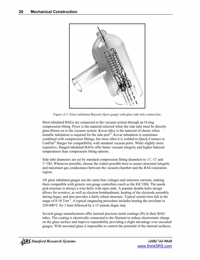
Figure A-2. Glass-tubulated Bayard-Alpert gauge with glass side tube connection.
Most tubulated BAGs are connected to the vacuum system through an O-ring compression fitting. Pyrex is the material selected when the side tube must be directly glass-blown on to the vacuum system. Kovar alloy is the material of choice when metallic tubulation is required for the side port85. Kovar tubulation is sometimes combined with compression fittings, but most often it is welded to Quick-Connect or ConFlat® flanges for compatibility with standard vacuum ports. While slightly more expensive, flanged tubulated BAGs offer better vacuum integrity and higher bakeout temperatures than compression fitting options.
Side tube diameters are set by standard compression fitting diameters to ½", ¾" and 1" OD. Whenever possible, choose the widest possible bore to assure structural integrity and maximum gas conductance between the vacuum chamber and the BAG ionization region.
All glass tubulated gauges use the same bias voltages and emission currents, making them compatible with generic ion-gauge controllers (such as the IGC100). The anode grid structure is always a wire helix with open ends. A popular double-helix design allows for resistive, as well as electron bombardment, heating of the electrode assembly during degas, and also provides a fairly robust structure. Typical sensitivities fall in the range of 8-10 Torr-1. A typical outgassing procedure includes heating the envelope to 250-400°C for 1 hour followed by a 15 minute degas step.
Several gauge manufacturers offer internal precious metal coatings (Pt) in their BAG tubes. The coating is electrically connected to the filament to reduce electrostatic charge on the glass surface and improve repeatability providing a slight advantage over uncoated gauges. With uncoated glass it impossible to control the potential of the internal surfaces,

Mechanical Construction 27
(408)744-9040 Stanford Research Systems www.thinkSRS.com
which results in uncontrolled electron and ion trajectories within the gauge and reduced measurement accuracy and repeatability.
Long term stability is affected by changes in the electrode structure particularly after repeated thermal cycling. High stability tubulated gauges with spring tensioned (sag-free) filaments and reinforced supports that provide improved measurement stability and accuracy without adding any significant cost are available from at least one manufacturer and are worth considering.
Broad-range glass tubulated BAGs are available from many different manufacturers, and under several different trade names. These gauges are designed to operate all the way up to 10-1 Torr (with 0.01 mA emission current above 10-3 Torr) while still providing a sensitivity factor of 8 Torr-1. They are easily identified because of the narrow grid design (12 mm diameter x 46 mm long), a thoria-coated filament, and a grounded platinum coating on the inside of a reduced diameter (41 mm vs. the traditional 57 mm) glass tube. However, they have been shown to be susceptible to large time-dependent instabilities and non-linearities86 that must be carefully considered during measurements.
Glass-tubulated BAGs are fragile and present a safety hazard due to implosion if not adequately shielded. Whenever possible, place them where they cannot be bumped, and be particularly careful during installation. A common problem is crushed side tubes due to excessive tightening of compression fittings. If possible, install the gauge so that the filament is visible during operation. A quick visual check might save a tungsten filament from burnout during a venting or gas loading operation. The preferred mounting orientation is with the filament and anode grid in a vertical position, with the connectors on top. This position minimizes the electrode distortion caused by gravity pull and thermal cycles.
Tubulated gauges with single and dual filament designs are available. Both tungsten and thoriated-iridium filament options are offered. Filaments are not replaceable, making the single filament gauges disposable after a burnout (A maintenance cost that must be considered!). The amount of power required to operate the filament can vary significantly from one gauge to another, depending on filament dimensions and material.
Glass tubulated gauges may be significant sinks of gas molecules and exhibit a certain pumping capacity that is usually time-dependent. This pumping is due to both chemical and electrical effects. The effect usually saturates after approximately three months of operation. The best way to handle this, is to provide a large conductance connection between the gauge and the vacuum system. A glass envelope gauge with 1" tubulation is recommended for applications requiring pressure measurements down to the 10-10 scale, ¾" tubulation is adequate for routine pressure measurements above 10-8 Torr.
Glass when heated permits permeation of helium from the atmosphere. Remember this effect while leak testing your vacuum system! If helium leak testing with the ion gauge is common practice in your facility consider an all metal gauge instead.
BAGs require few electrical connections; however, there is no standard mating socket that will work with all gauge designs. It is usually the user’s responsibility to assure that the correct electrical connections are made at the gauge pins. The correct pinouts for a gauge can be obtained from the original manufacturer. Experienced users can usually
28 Mechanical Construction
Stanford Research Systems (408)744-9040 www.thinkSRS.com
identify the different pins by visual inspection. Wrong connections can cause damage to equipment and may be dangerous for the vacuum system operator.
Note Stanford Research Systems offers a line of BAG connection cables (O100C1, O100C2 and O100C3) that make it easy and safe to connect almost any commercially available gauge to the IGC100 controller without having to be a gauge expert!
Tubulated gauges owe their popularity to their low cost, convenient measurement range, and ease of mounting. Their accuracy is more than adequate for most vacuum applications since very often a 'rough' pressure indication is all that is required by the vacuum operator to define the status of a vacuum system.
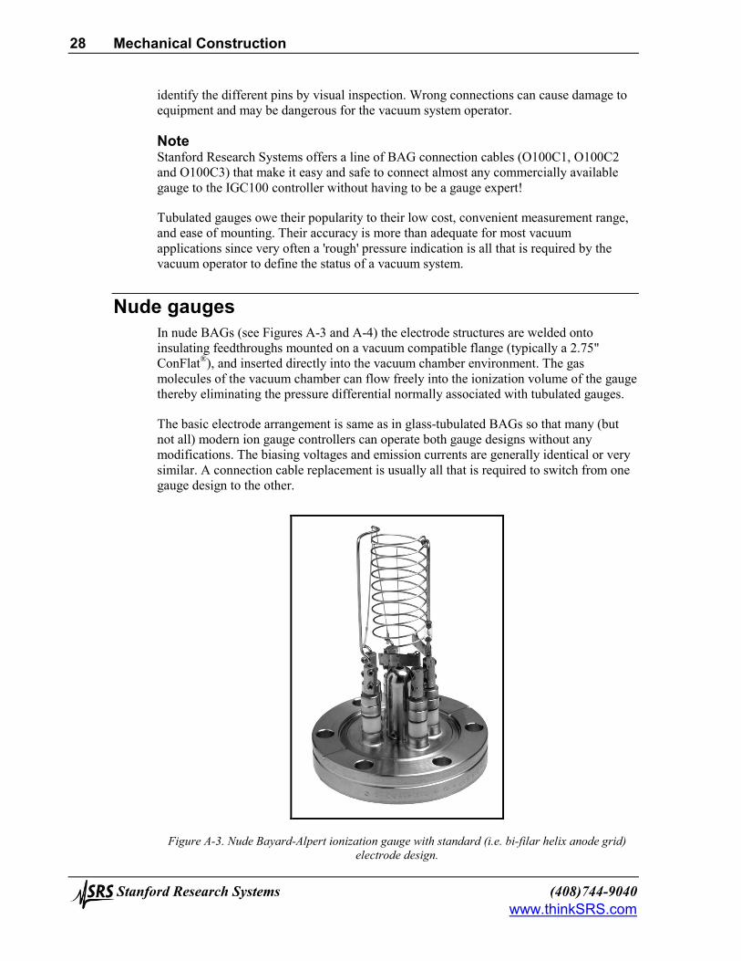
Nude gauges In nude BAGs (see Figures A-3 and A-4) the electrode structures are welded onto insulating feedthroughs mounted on a vacuum compatible flange (typically a 2.75" ConFlat®), and inserted directly into the vacuum chamber environment. The gas molecules of the vacuum chamber can flow freely into the ionization volume of the gauge thereby eliminating the pressure differential normally associated with tubulated gauges.
The basic electrode arrangement is same as in glass-tubulated BAGs so that many (but not all) modern ion gauge controllers can operate both gauge designs without any modifications. The biasing voltages and emission currents are generally identical or very similar. A connection cable replacement is usually all that is required to switch from one gauge design to the other.
Figure A-3. Nude Bayard-Alpert ionization gauge with standard (i.e. bi-filar helix anode grid) electrode design.

Mechanical Construction 29
(408)744-9040 Stanford Research Systems www.thinkSRS.com
Nude BAGs are always more expensive than glass-tubulated designs. When connected to a suitable controller, they provide pressure readings between 10-3 and 4x10⁻¹⁰ Torr (typical X-ray limit), with extended UHV versions reaching a 2x10-11 Torr low limit. Typical sensitivities fall in the range of 8-10 Torr-1 for standard gauges and 25 Torr-1 for the extended UHV versions. Extended UHV versions are easily identified by the fragile closed end design (squirrel cage) of their anode grid and the thinner collector wire.
Since the elements are exposed, and easily accessible, most nude ion gauges are designed with replacement filament assemblies. This allows filaments to be replaced after a burnout without having to dispose of the gauge (an important cost saving feature!). Unless a viewport is available, it is generally not possible to see the filament once the gauge is mounted on a port, making the filament more susceptible to accidental and catastrophic overpressures.
With the exception of UHV versions (EB only), conventional nude BAGs include a double-helix anode grid design that allows for resistive, as well as electron bombardment, heating of the electrode assembly during degas.
The sensitivity of nude ion gauges is affected by the way it is mounted on the system87. This effect was recently demonstrated by a careful study, which showed that when the dimensions or shape of the gauge’s metal envelope are changed there can be a dramatic effect (up to 2X) on the absolute magnitude of the gauge’s sensitivity. There may also be a change in the relative dependence of its sensitivity on pressure. If these effects are not taken into account, the accuracy and consistency of the measurements performed with the gauge will be compromised. The envelope must be considered an integral part of the ionization gauge when specifying sensitivity. The practical consequence of these findings is that nude ion gauges must be calibrated in situ, or in an environment that exactly matches the one experienced by the gauge during its measurements. It is common practice to calibrate and operate nude ion gauges inside a nipple 38 mm ID x 100 mm long, with a screen at the input port. The input screen is necessary to eliminate the collection of ions produced somewhere else in the vacuum system, and attracted by the exposed electrodes of the ion gauge.

30 Mechanical Construction
Stanford Research Systems (408)744-9040 www.thinkSRS.com
Figure A-4. Nude Bayard-Alpert ionization- UHV extended. Notice closed ends (squirrel-cage design) and fine wire design of anode grid.
Nude ions gauges are the choice of many UHV practitioners who appreciate the enhanced vacuum integrity provided by its mounting flange, the unrestricted conductance to the vacuum chamber, the reduced outgassing provided by the minimal surface area of its surroundings, and the higher bakeout temperatures that it can handle. Typical nude gauges can be baked to 450°C without any effect on performance. Nude ion gauges are the definitive solution to the gauge pumping problems experienced in tubulated gauges. The unrestricted conductance to the vacuum system also provides faster response to pressure changes in the chamber.
Extended UHV gauges provide the most cost-effective alternative for pressure measurements in the low 10-10 ranges typically accessed in surface science and extreme high vacuum experiments. The fine anode grid wires provide an enhanced open area, increasing the pathlength of the electrons before colliding with the grid. This effect, along with the closed ends, increases the sensitivity of the gauge by about a factor of two, relative to conventional BAG designs with open grids. The thin collector wire reduces the X-ray induced residual current by minimizing the collisional cross section with the X-rays emitted from the grid. The combination of enhanced sensitivity and reduced X-ray induced residual current is responsible for the extended X-ray limit. The effect of ESD is also relatively smaller in these gauges, since the thinner collector wire (0.125 mm vs. 0.25 mm) is very ineffective at collecting the energetic ions produced by electron stimulated desorption from the grid. The main limitation of the UHV design is the reduced linearity of the pressure gauge readings at upper pressures, starting sometimes as early as 10-5 Torr88.
Mechanical Construction 31
(408)744-9040 Stanford Research Systems www.thinkSRS.com
High-accuracy gauges One of the most significant developments in BAG design in recent years has been the introduction of the 'high-accuracy gauge' design89. High-accuracy gauges operate based on the same ionization principles as nude and tubulated gauges; however, they provide highly accurate, reproducible and stable pressure readings by systematically avoiding the known problems associated with traditional gauge designs.
The long-term stability, accuracy and gauge-to-gauge reproducibility of pressure measurements in high-accuracy gauges are assured by the unique design and precise manufacturing applied to their construction.
In a commercially available design90, dual, independent, thoria coated, ribbon filaments are carefully positioned relative to the anode axis and maintained in tension by refractory metal springs. Consequently, the filaments exhibit negligible bow, sag or twist with use, assuring stable and reproducible electron trajectories over time. Partial end-caps are employed to extend the radial electric field over a much larger area of the anode grid while at the same time short filaments are used to introduce electrons away from the end regions of the anode, assuring stable ion production conditions within the ionizer. The end-capped anode is precision assembled and stress-relieved so that it maintains its exact shape and position even after high temperature degassing. Electrode positions relative to wall are identical from gauge to gauge to assure reproducibility of measurements. A grounded conductive shield completely surrounds the anode-cathode structure to help provide a stable electrical environment for charged particle trajectories. The entire shield is designed to remain dimensionally stable over time and to have the same dimension from gauge to gauge within close tolerances. A grounded perforated high conductance shield over the port electrically isolates the electrode structures from the rest of the vacuum system.
Two different collector wire diameters of 0.005" and 0.040" are used. The thicker collector wire, precisely located at the anode axis, is so effective at collecting ions (50 Torr-1 sensitivity) that it helps extend the upper pressure limit to 10-2 Torr while keeping the X-ray limit at 10-10 Torr. The thinner collector wire, while providing a lower sensitivity, extends the X-ray limit into the low 10-11 Torr range for performance compatible with ultra- and extreme-high vacuum applications.
The premise is simple, high accuracy gauges provide long-term, stable, accurate, gauge-to-gauge reproducible measurements in a way that is unmatched by any other BAG design. Current state-of-the art midrange accuracy specifications for uncalibrated high-accuracy gauges are 6%, and they get better for individually calibrated gauges.
Note It is important to mention at this early point that no independent studies on the long term behavior of high accuracy gauges have yet been reported in the vacuum literature. All long term stability claims are based on experiments performed, and data published, by the gauge manufacturer itself. No certified independent vacuum calibration laboratory has looked at these gauges over a long period of time and compared their long term behavior to that of traditional designs.

32 Mechanical Construction
Stanford Research Systems (408)744-9040 www.thinkSRS.com
Full enjoyment of the enhanced accuracy and stability capabilities of high-accuracy gauges requires the use of high-quality controllers such as the IGC100. Traditional (older design) controllers can contribute up to 15% uncertainty to a BAG readout91.
High accuracy gauges are stable and reproducible enough, that it makes sense to calibrate them. Using the IGC100, it is possible to perform NIST traceable calibrations on individual gauges and store calibration information on Memory Cards that can be loaded into the controller’s memory when needed. Stored values of gauge sensitivity track the actual gauge sensitivity across the entire pressure range, providing real time correction for the non-linearities that lead to errors in traditional gauge systems. Individually calibrated high accuracy gauges offer midrange reading accuracies better than 3% (close to spinning rotor gauge performance)92.
High accuracy gauges are usually expensive, costing up to 10 times as much as a glass tubulated gauge, but they make a lot of sense in strictly controlled vacuum process environments where pressure reading inaccuracies can lead to reduced yields and increased production costs. When properly selected they can pay for themselves very quickly! The gauge-to-gauge reproducibility is a welcome feature when forced to switch to a new gauge right before trying to reproduce a production run. Calibrated high accuracy gauges are also cost-effective NIST traceable transfer standards, providing accuracies comparable to spinning rotor gauges over a larger pressure range. It is common practice for pressure calibration laboratories to use high-accuracy gauges as transfer, check and working standards. Keep in mind that whereas the gauge-to-gauge reproducibility claims for high accuracy ion gauges are generally well accepted by vacuum users, the longer term stability of these gauges has not yet been verified by any independent vacuum calibration lab.
Note Consult the application note, “Using the IGC100 with STABIL-ION® gauges” for details on the connection of high accuracy gauges to the IGC100.
Tiny Gauges Miniaturization has not escaped BAG designs. Almost every vacuum gauge manufacturer now offers a version of 'tiny' ionization gauge93.
Tiny gauges are a modern alternative to glass tubulated gauges and are likely to become relatively more important in the future. They eliminate glass gauge accidents by relying in all-metal construction. They offer an operational range that overlaps or sometimes exceeds that of traditional tubulated designs. The reduced size also minimizes the power requirements of the filament resulting in less heat being dissipated into the vacuum chamber and reduced outgassing.
A miniaturized, all-metal ionization gauge that retains the traditional inverted-triode design, operating voltages, good sensitivity and low X-ray limit of the conventional glass tubulated BAG has recently become commercially available94. This tiny gauge (5% of the conventional volume) utilizes a dual collector design to increase ion collection efficiency (20 Torr-1 typical) while at the same time providing a wider usable pressure range that extends from 3x10⁻¹⁰ (X-ray limit) to 5x10⁻² Torr.

Mechanical Construction 33
(408)744-9040 Stanford Research Systems www.thinkSRS.com
Note The IGC100 controller is compatible with most commercially available tiny-BAGs and a connector adapter is all that is usually required to operate them. Consult the application note, “Using the IGC100 with MICRO-ION® gauges” for details on a specific tiny-gauge connection example.
Tiny gauges are more expensive than tubulated designs (up to 4 times) and are usually only available with dual thoriated (burn-out resistant) filaments. Filaments are not replaceable, making the gauges disposable after filament failure. Both flanged and tubular mounting options are available.
No reports on the repeatability, short- and long-term stability, and gauge-to-gauge reproducibility of tiny gauges are currently available since the gauges have only been recently introduced into the market. However, It is probably fair to assume that their accuracy specifications will be comparable to those of glass tubulated ion gauges.

34 Filament Considerations
Stanford Research Systems (408)744-9040 www.thinkSRS.com
Filament Considerations Careful consideration must be dedicated to the choice of filament material.
Filaments are based on thermionic phenomena95- the emission of charged particles from the surface of a conductive material or compound at high temperature. The emission of charged particles depends on the work function96 of the material, defined as the energy, measured in eV, required to move an electron from Fermi level outside the surface.
Filaments, in both wire and ribbon shapes, are required to
• supply a stable electron emission current with reasonable energy input and filament temperature
• have reduced chemical reactivity with the rarefied environment being measured • have a reduced evaporation rate at the operating temperature (i.e. long life) • have a vapor pressure at least one tenth of the lowest pressure that has to be measured • have low levels of ionic and neutral molecule outgassing compatible with the lowest
pressure measurements.
It is commonly believed that the filament in a BAG presents a reliability problem (especially when compared to Cold Cathode Gauges) and it is often true that the operating life of hot cathode ionization gauges is determined by filament lifetime. However, unless damaged by ion bombardment, high pressure operation, chemical reactions or severe contamination, filament lifetimes are usually in the thousands of hours (usually years).
The optimum choice of filament material is very application dependent, and interactions of the gas with the cathode material must be considered during filament selection.
Several attempts have been made to replace hot filaments with cold electron emitters in BAGs97; however, no commercially available gauges have resulted from those efforts yet.
Filament Materials The filament materials used in BAGs can be grouped into two classes: (1) pure metals and (2) oxide-coated cathodes. This section only concentrates on the materials commonly encountered in commercially available gauges. For information on less common materials, consult the excellent primer by Gear98 and the work by W. Kohl99.
Among pure metals, tungsten (W) is used on a large scale in ionization gauge heads operated in medium and high vacuum environments. The operating temperature of tungsten cathodes is between 1900°C and 2200°C. At this high operating temperatures, contaminating electronegative gases, which would increase the work function and reduce emission levels, are rapidly evaporated from the filament surface. As a result, tungsten filaments provide more stable gauge operation compared to metal oxide cathodes. However, this advantage is usually at the expense of (1) large outgassing levels as a result of the elevated temperatures in the surrounding walls and (2) an increased reactivity with chemically active gases that react at the filament to produce other gases. Chemical reactions as well as a high vapor pressure (10-8 Torr at 2200K) make W a bad choice for

Filament Considerations 35
(408)744-9040 Stanford Research Systems www.thinkSRS.com
UHV measurements. Glass tubulated BAG tubes with dual W filaments are often the best choice for ion implantation applications.
The lifetime of W filaments, as determined by typical evaporation rates, is typically 10-20 hours at 10-3-10-2 Torr, and about 1000 hours at 10-6 Torr (gas dependent). However, accidental exposure to air and/or mechanical mishandling will damage tungsten filaments irreversibly. Tungsten is not seriously affected by hydrocarbons and halogens during operation.
Thoria-coated iridium (ThO2Ir) filaments are the oxide-coated cathodes most commonly encountered in BAG heads manufactured in the US100. These cathodes are prepared by depositing a layer of thoria (i.e. thorium oxide) on a base metal of iridium by cataphoresis. The coating is then preconditioned101 by operation in a vacuum at about 1800°C. Iridium is the preferred substrate because it is very resistant to oxidation and does not burn out if exposed to high air pressures while hot. ThO2Ir filaments are very resistant to poisoning and do not burn out if exposed for a short time during operation to a sudden inrush of air. In fact, BAGs with ThO2Ir filaments are known to survive several brief exposures to atmospheric air, without any performance deterioration.
ThO2Ir filaments operate at a 'relatively cool' temperature of ≈1400°C, resulting in reduced outgassing and chemical reactivity with active gases when compared to W filaments. These two advantages, make ThO2Ir filaments the preferred filament choice for measurements in the ultrahigh vacuum region. Most thoriated filaments are ribbon shaped to minimize heat flow to the ends which results in reduced outgassing.
Thoria coatings are very sensitive to electron and ionic bombardment. As a consequence, electron bombardment degassing must be minimized in gauge heads with ThO2Ir filaments. A thorough bakeout is a better alternative in this case.
The material choice is dictated by the application. Tungsten filaments are by far the least expensive and the most popular. The use of ThO2Ir filaments is recommended for systems that are frequently brought to atmosphere (voluntarily or not!). ThO2Ir is the only practical alternative for operation above 10-3 Torr. Some investigators102 have obtained results suggesting that gauges with tungsten filaments provide better stability than do gauges with thoria coated versions. The current belief is that it is not the filament material that causes the improvement, but rather the shape of the cathode. Tungsten cathodes are typically made as tight springs stretched between rigid posts that tend to move relatively little during long term use compared to the hairpin shaped or relatively unsupported ribbon shaped thoria-coated cathodes. Whenever possible opt for spring tensioned filaments in your BAG heads, particularly those with hair pin designs.
Dual filament assemblies provide security against filament burnout if the system cannot be brought to atmosphere to change the gauge. They are the most cost-effective alternative for tubulated gauges where filament replacement is not an option. Do not expect both filaments to give identical readings in a dual filament gauge unless a high accuracy gauge is being used. Simple methods for in-house replacement of tungsten filaments in nude gauges have been described in the vacuum literature as a cost-effective alternative if high accuracy and reproducibility is not a requirement in the pressure measurements performed by the repaired gauge103.

36 Filament Considerations
Stanford Research Systems (408)744-9040 www.thinkSRS.com
Filament Reactions Chemical reactions at the hot filament can occur and usually belong to one of two groups: (1) thermal dissociation of gas or vapor at the hot cathode and further recombination of the resulting fragments with impurities in the gas or on the walls or (2) combination of gas with the filament material.
Chemical reactions involving the hot filament surface and the gas molecules can significantly affect the chemical composition and the total pressure of the gas environment in a high vacuum system104. There is a large dependence of these reactions on the material chosen for the cathode and the type of gas in the environment. Some of the processes triggered by these reactions include: (1) active pumping of selected gas components, (2) outgassing of impurities into the vacuum environment, (3) thinning of the filament, and (4) poisoning of the filament surface (change in work function and emissivity).
Gases and vapor usually found in measuring systems are oxygen, hydrogen and water vapor.
Oxygen Oxygen molecules react with the hot tungsten cathode and dissociate into atomic oxygen. The atomic oxygen then reacts with the carbon impurities at the surface to yield CO and CO2. Since carbon constantly diffuses to the surface from the bulk, CO is continuously generated by this process. Even after the carbon is consumed, atomic oxygen still combines with carbon containing impurities present on the gauge walls, yielding CO.
Oxygen atoms interact with tungsten and produce oxides (WO2, WO3) as surface species. These species affect the work function of the material and also make the wire very brittle. These chemical processes result in the removal of oxygen from the system, therefore an ion gauge with W filament acts as a pump for oxygen.
Hydrogen Hydrogen molecules dissociate to atomic hydrogen in the presence of a tungsten cathode at temperatures > 800°C. The atomic hydrogen reacts with glass or metal surfaces to yield CO, H2O, and CH4. This fast removal of hydrogen from the gas results in anomalously high pumping speeds for hydrogen in BAG heads with W filaments.
After adsorbing a monolayer of hydrogen, the work function of a tungsten filament is significantly increased (+0.35 eV typical) and the filament must run hotter to achieve the same emission current.
Water Water vapor reacts with hot tungsten cathodes initiating an efficient transport of tungsten molecules to the gauge walls. This process, known as the water vapor cycle, includes several steps: (1) water dissociates at the filament into atomic oxygen and hydrogen, (2) the atomic oxygen reacts with W to form a volatile oxide that deposits on the glass walls of the gauge head as a film, (3) atomic hydrogen reduces the film back to W thus setting free water vapor, which repeats the cycle. The cathode lifetime is severely compromised by this process. CH4, CO and CO2 are also formed at the filament as a result of chemical reaction with water.
Filament Considerations 37
(408)744-9040 Stanford Research Systems www.thinkSRS.com
Hydrocarbons Hydrocarbons, such as methane and pump oils, backstreaming from vacuum pumps can dissociate on hot filaments to produce CO.
Emission of ions and neutrals The emission of positive ions and neutrals from heated surfaces is a common occurrence that can affect the performance of BAGs in the UHV range.
Although the positive ions cannot normally reach the collector because of the grid potential, the emission of positive ions is accompanied by a larger flux of neutrals. These neutrals can then be ionized and reach the collector giving a pressure independent current which ultimately limits the lowest measurable pressure. The evaporation of neutrals and ions can be minimized by heating the pure metal cathodes at high temperature for prolonged periods of time while pumping the gauge head.

38 Accuracy and Stability
Stanford Research Systems (408)744-9040 www.thinkSRS.com
Accuracy and Stability The two main variables that affect the accuracy and reproducibility of pressure measurements are (1) gauge-to-gauge reproducibility and (2) long-term stability.
Reproducibility Gauge-to-gauge reproducibility has been examined by the High Vacuum Group at NIST (National Institute of Standards and Technology, Gaithersburg, MD). The sensitivities of a large collection of commercially available BAGs were carefully calibrated and surprisingly large sensitivity factor variations were observed even amongst seemingly identical gauge heads. The reported ranges105 in gauge constants are summarized next:
• Glass tubulated with opposed W filaments: +20 to –10%
• Glass tubulated, with side-by-side W filaments: +25 to –5%.
• Glass tubulated, with thoria filament: +13 to –38%
• Nude UHV version, with thoria filaments: +22 to –65%
The gauge-to-gauge reproducibility and long-term stability of broad-range glass tubulated gauges was also studied at NIST106. A check of the sensitivity factors for the seven gauges tested found the nitrogen sensitivities to vary between 52 and 67% of their specified values. Significant non-linearities as a function of pressure were also evident. Instabilities were in the order of 10%. Some of the gauges were inoperable in hydrogen environments.
The scatter of sensitivities is easily corrected by calibration. However, many users simply accept the catalog values for sensitivity factors without correction. This practice is only acceptable for applications where a rough determination of pressure is necessary.
As a rule-of-thumb:
• gauge-to-gauge variations can be considered to be an average ±15%.
• For any one uncalibrated gauge, an accuracy of ±25% at midrange should be considered good.
• Measurement accuracies better than 1% are not achievable with BAGs.
• Calibration of the gauge is recommended whenever an accuracy better than 50% is required.
Stability Long-term stability of measurements over long operating times is also very important for accurate measurements. Filippelli and Abbott107 compared repeated calibrations of 20 gauges used as transfer standards in industrial applications (returned to NIST for recalibration every one to two years several times) and concluded that for tubulated gauges with W filaments the standard deviation of the maximum difference between successive calibrations was 3% (maximum 12%) while for gauges with thoria cathodes it
Accuracy and Stability 39
(408)744-9040 Stanford Research Systems www.thinkSRS.com
was 6% (maximum 18%). In most cases, the sensitivity of the gauges tended to decrease. The change in gauge sensitivity did not occur in a uniform manner with time of use.
P. C. Arnold and S. C. Borichevski108 studied the stability and gauge-to-gauge reproducibility of eleven 'conventional' BAGs with various different mechanical constructions and thoriated filaments and reported much larger sensitivity variations ranging from –57 to +72% over the first 4000 hours of operation. Gauge-to-gauge variations between –20 and +32% were observed for five virtually identical glass tubulated gauges after 48 hours of operation. The gauges were operated at 10 mA of emission current (compare to 1 mA for NIST), and were degassed daily for 20 minutes (not recommended by NIST) which might explain the poor performance of the tested gauges.
The long term stability of a BAG is highly affected by its history (see 'History Dependence' in this application note). Gauge sensitivity factors are seen to change with time even under the carefully controlled conditions of a standards laboratory. Industrial systems with gases that contaminate the electrodes are much worse. Unfortunately, there is very little written on the effects of contamination, for, as might be expected , there are wide variations in performance, depending upon both the type of gauge and its treatment in the vacuum system. Two very useful papers109 that deal with the causes of non-stability in BAGs are found in the references, and should be consulted for details. An excellent set of 'Recommended Operating Procedures' for better BAG stability was compiled by Tilford110 and is highly recommended.
Partial restoration procedures for heavily contaminated glass-tubulated BAGs have been reported in the vacuum literature111. These procedures are only recommended for inoperable gauges, and in general only restore the sensitivity of the gauge within a factor of two of a new gauge.
Systematic differences in sensitivity are observed between the two filament positions in BAGs with dual filament assemblies and conventional design. An individual calibration for each filament is necessary for accurate measurements.
Confidence in gauge stability can be increased by periodically checking the gauge against a check gauge (work standard). This will be most effective if the check gauge is of proven stability and/or is protected from abuse or unnecessary use.
Even with inactive gases, time must be allowed for gauge equilibrium to be reached following pressure changes. Limited experimental data is available in this area. Some general rules of thumb, applicable to transient measurements, can be obtained from Tilford’s work112:
• Tungsten (W) filament gauges accommodate to increasing nitrogen pressure faster than thoria-coated filament gauges.
• W filament gauges respond to a three fold increase in pressure to within 0.1% within a few minutes.
• The response is slower in a dirty system or with active gases.
• The response to decreasing pressure is slower by several orders of magnitude.

40 Accuracy and Stability
Stanford Research Systems (408)744-9040 www.thinkSRS.com
These effects are compounded by conductance limitations of the gauge tubulation and the time constant of the electrometer.
One of the most significant developments in BAG design in recent years has been the introduction of the 'high-accuracy gauge' design113. High-accuracy gauges operate based on the same ionization principles as nude and tubulated gauges; however, they provide highly accurate, reproducible and stable pressure readings by systematically avoiding the known problems associated with traditional gauge designs. The long-term stability, accuracy and gauge-to-gauge reproducibility of pressure measurements in high-accuracy gauges are assured by the unique design and precise manufacturing applied to their construction (see 'Mechanical Construction' in this application note for details).
High accuracy gauges are stable and reproducible enough, that it makes sense to fully calibrate them. Using the IGC100 it is possible to perform NIST traceable calibrations on individual gauges and store calibration information in special Memory Cards that can be downloaded into the controller’s memory when needed. Stored values of gauge sensitivity track the actual gauge sensitivity across the entire pressure range, providing real time correction for the non-linearities that lead to errors in traditional gauge systems. Individually calibrated high accuracy gauges offer midrange reading accuracies better than 3% (close to spinning rotor gauge performance) 114.
Full enjoyment of the enhanced accuracy and stability capabilities of high-accuracy gauges requires the use of high-quality controllers, with properly specified electronics, such as the IGC100. Traditional (older design) controllers can contribute up to 15% uncertainty to a BAG readout115.

Degassing 41
(408)744-9040 Stanford Research Systems www.thinkSRS.com
Degassing The cleanliness of an ionization gauge has a considerable effect on its performance.
The filament is rapidly outgassed when first turned on. The radiant heat from the hot wire then causes outgassing from nearby surfaces including electrode supports and envelope walls. These effects are readily seen following the pressure indication of the BAG immediately after the filament is switched on.
The heat generated by the filament during normal operation is not enough to effectively clean the grid and collector surfaces, and effective outgassing of the envelope requires bakeout (400°C for 1 hour is typical for glass tubulated gauges).
To reduce the outgassing in a gauge to a negligible level, and minimize the effects of ESD on low pressure measurements, the outgassing technique known as Degassing is often employed to drive off the gas molecules adsorbed on the anode grid structure. During degas the electrodes are degassed by heating to a temperature of 900°C (nominal) for 10-20 minutes. The electrode heating is accomplished by either electron bombardment (EB Degas) or by passing a high current through the grid (I2R Degas) .
In conventional gauges, particularly those manufactured in the US, the anode grid is in the form of a single or double helix designed to allow a current to be passed through to provide ohmic heating. Distortion and sagging can occur here if the temperature attained during degassing is too high. Modern gauge heads use molybdenum or tungsten grids to avoid or minimize this problem. Typical powers used during resistive heating degassing are about 70 Watts (7 Vdc @ 10 A). All helix gauges can also be degassed by EB as well.
Gauges made with squirrel-cage grids (UHV nude BAGs) can accept only EB degas. During EB degas, the grid (and sometimes the collector as well) are biased at around 500 Vdc and bombarded with electrons from the filament (biased at 30 Vdc). An emission current of a few tens of milliamps is sufficient to heat the electrodes (usually molybdenum) to a dull red. The combination of heating with the electron bombardment of the electrodes provides a very effective cleaning procedure.
Degassing is best carried out, while the rest of the vacuum system is also being baked to avoid degassing products from adsorbing onto the walls of the chamber.
It is common practice for many HV users to automatically degas the gauge and/or bake the vacuum system after the gauge is exposed to ambient, or after surface contamination is suspected. BAGs will be unstable for several hours following degassing until the chemical composition and adsorbed layers on the newly cleaned surfaces reach equilibrium. This effect must be carefully considered for high accuracy determinations.
All commercially available BAGs can be degassed by electron bombardment. However, thoriated filaments can be rapidly damaged by the intense ionic bombardment that they experience when EB degassing takes place at pressures above 10-5 Torr. To extend filament lifetime, minimize the emission current during degas and extend the degas time to compensate. Keep the EB degas power under 40 W for all thoriated filament gauges.

42 Degassing
Stanford Research Systems (408)744-9040 www.thinkSRS.com
Some vacuum researchers suggest bombarding the collector wire along with the anode grid during EB degassing. This approach leads to clean electrodes, but it is intrinsically dangerous in practice. Instead, it is recommended to keep the collector connected to the electrometer to get a rough estimate of the pressure during degas. EB degassing at pressures >5x10⁻⁵ Torr can damage the gauge, and injure the user if the system is not properly grounded (see the Safety and Health Considerations section for details)
The recommendation from the NIST High Vacuum Group is to eliminate degassing by high temperature heating of the grid (whether resistive or electron bombardment). For baked systems, their observation is that gauges can be effectively outgassed by simply operating them at normal emission currents while the BAG and vacuum system are baked. For unbaked systems, the gauge can be baked and outgassed by thermally insulating it with fiberglass. Degassing by electron bombardment is only recommended if (1) the gauge is heavily contaminated or (2) after exposure to surface active gases such as O2
116. Whenever possible minimize the emission current during degas and extend the degas time to compensate.
Note The IGC100 offers EB degas with fully adjustable Degas power and Degas time.

Safety and Health Considerations 43
(408)744-9040 Stanford Research Systems www.thinkSRS.com
Safety and Health Considerations
Electric Shock DANGER! The most serious hazard with BAGs and their controllers is electrical shock117.
During normal operation the anode grid of a BAG is biased at about 180 Vdc and connected to a power supply capable of supplying 10 mA. This is enough to cause defibrillation and even death. During EB degas, the anode grid is biased to 500 Vdc at currents of up to 160 mA! Contact with this supply, with a direct current path through the body, would very likely be fatal to anybody.
A more subtle way of contacting the high voltage during EB degas was described by Morrison118. If EB degas is allowed at pressures above 10-4 Torr, a plasma might develop inside the gauge capable of providing a current path to metal portions of the system. If the system is not properly grounded, touching the charged metal section may cause a lethal shock. The effect might remain even after the filament is shut down (depending on the amount of energy stored)!
A well designed gauge system should include suitable cables, connectors and grounds. A user should never touch any connector or the gauge when the power is on. Both the controller and the vacuum system must be earth grounded with heavy gauge (12 AWG) wire.
Thoria Alpha Emission In gauges with thoriated filaments, exposure to the alpha particles emitted by thorium is of concern to some users. The use of yttria coated iridium filaments is recommended in those cases as an alternative. Most gauge manufacturers offer this filament material as an option.
Glass breakage With glass tubulated gauges, breakage of the glass envelope can result in implosion and the associated danger of flying glass. Whenever possible protect the gauge with a shield and provide stress relief for the cables. Do not overtighten the O-rings of the compression fittings traditionally used to connect glass tubulated gauges to vacuum systems. All-metal nude gauges should also be considered if the risk of breakage is high.
Burns Gauge envelopes can get hot, and cause burns if touched during operation.

44 Safety and Health Considerations
Stanford Research Systems (408)744-9040 www.thinkSRS.com
X-rays The X-rays produced at the anode grid, and responsible for the X-ray limit, are not a risk since they do not have enough energy to penetrate through the gauge envelope. This is also true for the X-rays generated during EB Degas.

References 45
(408)744-9040 Stanford Research Systems www.thinkSRS.com
References
1 R.T. Bayard and D. Alpert, Rev. Sci. Instr. 21 (1950) 571; D. Alpert, "New Developments in the Production and Measurement of Ultra High Vacuum", J. Appl. Phys. 24(7) (1953).
2 J. M. Lafferty, "Foundations of Vacuum Science and Technology", John Wiley and Sons, NY, 1997, page 414.
3 K. Ishikawa, "Voltage Dependence of BAG Characteristics", Japanese Journal of Applied Physics", 4(6) (1965) 461. See also C. Tilford, J. Vac. Sci. Technol A3(3) (1985) 546, where the author reports 20% drops in sensitivity factors when the emission current is increased from 1 to 10 mA, with much larger changes above 10-5 Torr.
4 R. M. Paitich and D. D. Briglia, "Method and means for vacuum gauging", U.S. Pat. 4, 314,205 (1982); R. Paitich "New Controller extends the range of BA Ion Gauges", R&D, Dec. 1989 p.65.
5 J. H. Leck, "Total and Partial Pressure Measurement in Vacuum Systems", Blackie, Glasgow and Lonndon, 1989, page 102.
6 Above 10-3 Torr the ionization pathlength, L, of the electrons decreases becoming comparable to the dimensions of the gauge head.
7 G. J. Schulz J. Appl. Phys. 28 (1957) 1149, G. J. Schulz and A. V. Phelps, Rev Sci Instr 28 (1957)1051.
8 G. J. Schulz and A. V. Phelps, Rev Sci Instr 28 (1957)1051, J. A. Weinman, Rev Sci. Instr. 37 (1966) 636, J. S. Cleaver, J. Sci. Instrum. 44 (1967) 969, U. Beeck and G. Reich, Vacuum 24 (1974) 27. These are just some examples of high pressure gauges. For More information consult J . M. Lafferty, "Foundations of Vacuum Science and Technology", John Wiley and Sons, NY, 1997, page 426.
9 See for example, BAG model ETI8136, from Electron Technology Inc., www.etigauges.com.
10 Charles Tilford, K.E. McCulloh and H. S. Woong, "Performance Characteristics of Broad Range Ionization Gauge tube", J. Vac. Sci. Technol. 20(4) (1982) 1140.
11 A.R. Filipelli, "A miniature Dual-Collector Ionization Gauge", Proceedings of the 46th International Symposium, American Vacuum Society, Oct 25-29, 1999. Washington State Convention Center, Seattle Washington.
12 Albert Filipelli and Sharrill Dittmann, "Search for pressure dependence in the sensitivity of several common types of hot-cathode ionization gauges for total pressures down to 10-7 Pa", J. Vac. Sci. Technol. A 9(5) (1991) 2757.
13 J. T. Tate and P. T. Smith, Phys. Rev. 39 (1932) 270; P. T. Smith, Phys. Rev. 36 (1930) 1293.
46 References
Stanford Research Systems (408)744-9040 www.thinkSRS.com
14 T. A. Flaim and P. D. Ownby, "Observations on Bayard-Alpert Ion Gauge Sensitivities to Various
Gases", J. Vac. Sci. Technol 8(5) (1971) 661; R. Holanda, J. Vac. Sci. Technol. 10(1973) 1133; F. Nakao, Vacuum 25 (1975) 431; J.E. Bartmess and R. M. Georgiadis, Vacuum 33 (1983) 149 ; R. L. Summers, "Empirical observations on the sensitivity of hot cathode ionization type vacuum gauges", NASA Technical Note TN D-5285, National Aeronautics and Space Administration, Lewis Research Center, 1969; R. Holanda, "Sensitivity of hot-cathode ionization vacuum gauges in several gases", NASA Technical Note NASA TN D-6815, National Aeronautics and Space Administration, Lewis Research Center, 1972.
15 L. J. Kieffer and Gordon H. Dunn, "Electron Impact Ionization Cross section. Data for Atoms, Atomic Ions, and Diatomic Molecules: I. Experimental Data", Reviews of Modern Physics, 38 (1966) 1.
16 Charles Tilford, "Reliability of high vacuum measurements", J. Vac. Sci. Technol. A1(2) (1982) 152. See figure 6 for pressure dependence of relative sensitivity for some common gases.
17 P. A. Redhead, "The sensitivity of Bayard-Alpert Gauges", J. Vac. Sci. Technol. 6 (5) (1969) 848.
18 D. G. Bills, "Causes of nonstability and nonreproducibility in widely used Bayard-Alpert ionization gauges", J. Vac. Sci. Technol. A 12(2) (1994) 574.
19 Charles Tilford, "Sensitivity of hot cathode ionization gauges", J. Vac. Sci. Technol. A 3(3) (1985) 546.
20 P. C. Arnold, D. G. Bills, M. D. Borenstein and S. C. Borichevsky, "Stable and reproducible Bayard-Alpert Ionization Gauge", J. Vac. Sci. Technol. A 12(2) (1994) 580.
21 George Comsa, "Ion Collection in Bayard-Alpert Gauges" , J. Vac. Sci. Technol. 9 (1) (1971) 117.
22 At pressures below 10-7 Torr, ions which miss the collector at their first radial trip due to excessive angular momentum with respect to the collector axis, have practically no chance to collide with atoms during their axial drift.
23 Only a small fraction of this decrease is due to density changes caused by the rise in gas temperature.
24 E.V.Kornelsen, Proc. 3rd Intern. Vac. Congr., 1965 , Pergamon, Oxford (1966) , Vol. 1, page 65.
25 P. C. Arnold, D. G. Bills, M. D. Borenstein and S. C. Borichevsky, "Stable and reproducible Bayard-Alpert Ionization Gauge", J. Vac. Sci. Technol. A 12(2) (1994) 580.
26 D. G. Bills, "Causes of nonstability and nonreproducibility in widely used Bayard-Alpert ionization gauges", J. Vac. Sci. Technol. A 12(2) (1994) 574. See figure 4 for a picture of the effect of collector position on electron trajectories.
27 W. B. Nottingham in 1954 Vacuum Symposium Transactions (Committee on Vacuum Techniques, Bostion, 1955), p. 76.
28 R. N. Peacock and N. T. Peacock, "Sensitivity variation of Bayard-Alpert Gauges with and without closed grids from 10-4 to 1 Pa", J. Vac. Sci. Technol. A8 (4) (1990) 3341.
29 George Comsa, "Ion Collection in Bayard-Alpert Gauges" , J. Vac. Sci. Technol. 9 (1) (1971) 117.
References 47
(408)744-9040 Stanford Research Systems www.thinkSRS.com
30 C. Tilford, K. E. McCulloh and H. S. Woong, "Performance Characteristics of a broad range ionization
gauge tube", J. Vac. Sci. Technology 20(4) (1982) 1140.
31 R. Kauert et. al. ,"Numerical investigations of hot cathode ionization gauges", Vacuum 51(1)(1998) 53.
32 A minimum negative anode bias of 5Vdc is required for this purpose.
33 D. Alpert "New Developments in the Production and Measurement of Ultra High Vacuum", J. Apl. Phys. 24(7) (1953) 860. See fig 1(a) and text on page 862.
34 C. Tilford, K. E. McCulloh and H. S. Woong, "Performance Characteristics of a broad range ionization gauge tube", J. Vac. Sci. Technology 20(4) (1982) 1140. See comments on page 1142, including the results of figures 3 and 4 on the same page.
35 Standard "older design" BAG controllers can contribute as much as 15% uncertainty to readout when the root sum of the squares of the errors contributed by variations in electrode voltages, emission current, measurement of ion current and poor resolution is calculated. See, for example, brochure # 360138, 4-97, by Granville Phillips incorporated, page 12, where they describe the operation of high-accuracy gauges with their older controllers.
36 L. T. Melfi and F. A. Kern, "Variations in Gauge Constant as a Function of Emission Current in an Unshielded Open-end Grid BAG", NASA Technical Note, NASA TN D-3811. NASA, Langley Research Center, 1967.
37 P. J. Abbott and J. P. Looney, "Influence of the filament potential wave form on the sensitivity of glass envelope Bayard-Alpert gauges", J. Vac. Sci. Technol. A 12(5) (1994) 2911.
38 P. J. Szwemin, "The influence of external circuit on the ionization gauge stability", Vacuum 41 (1990) 1807.
39 N. Donkov and W. Knapp, "Control of Hot-Filament Ionization Gauge emission Current: Mathematical model and model-based controller", Measurement Science and Technology, 8(7) (1997) 798.
40 The emission current is typically <10 mA so the cable length has no detectable effect on grid bias voltage.
41 Shigemi Suginuma and Masahiro Hirata, "Dependence of sensitivity coefficient of a nude Bayard-Alpert type gauge on the diameter of the envelope", Vacuum 53 (1999) 177.
42 G. Carter and J. H. Leck, Br. J. Appl. Phys. 10 (1959) 364.
43 P. A. Redhead, "The sensitivity of Bayard-Alpert Gauges", J. Vac. Sci. Technol. 6 (5) (1969) 848.
44 L. G. Pittaway, J. Phys. Ed.:Appl. Phys. 3 (1970) 1113.
45 C. Tilford, K. E. McCulloh and H. S. Woong, "Performance Characteristics of a broad range ionization gauge tube", J. Vac. Sci. Technology 20(4) (1982) 1140. See comments on page 1143.
46 P. J. Abbott and J. P. Looney, "Influence of the filament potential wave form on the sensitivity of glass envelope Bayard-Alpert gauges", J. Vac. Sci. Technol. A 12(5) (1994) 2911.
48 References
Stanford Research Systems (408)744-9040 www.thinkSRS.com
47 A. R. Filippelli, "Influence of envelope geometry on the sensitivity of nude ionization gauges", J. Vac.
Sci. Technol. A 14(5) (19996) 2953.
48 P. C. Arnold, "Enhanced BAG with accuracy and Stability improved by Design and Construction", Proceedings of the 46th International Symposium, American Vacuum Society, Oct 25-29, 1999. Washington State Convention Center, Seattle Washington.
49 C. R. Tilford, "Reliability of high vacuum measurements", J. Vac. Sci. Technol. A 1(2) (1983) 152. See temperature comments on p. 159.
50 D. G. Bills, M. D. Borenstein and P. C. Arnold, US Patent 5422573, 1995.
51 R. A. Haefer, Vacuum, 30 (1980)193.
52 K. J. Close, D. Lane and J. Yarwood, Vacuum 29(1979) 249.
53 Tentative Recommended Practice for Ionization Gauge Application to Space Simulators, ASTM E296-66T, Appendix A2. Am. Soc. Test. Mater. ,Philadelphia.
54 The anode grid temperature in a conventional BAG can be raised to over 700K by the filament radiation at 10 mA of emission current as measured by Kendall in J. Vac. Sci. Technol A 17(4) (1999) 2041, and reported on p. 2043. The envelope of an uncoated, clean, glass-tubulated gauge usually operates at about 50°C.
55 For a list of references consult J. M. Lafferty, "Foundations of Vacuum Science and Technology", John Wiley and Sons, NY, 1997, page 438. For a careful study between 0.3 and 0.7 T consult: W. L. Pickles, and A. L. Hunt, " Calibration and characterization of Bayard Alpert Gauges operating in High Magnetic Fields", NASA, Center for Aerospace Information, Document # 8625754, 1985.
56 K. Jousten and P. Rohl, "Instability of the spatial electron current distribution in hot cathode ionization gauges as a source of sensitivity changes", J. Vac. Sci. Technol. A 13(4) (1995) 2266.
57 P. C. Arnold and D. G. Bills, J. Vac. Sci. Technol. A2(1984) 159.
58 The operating life of a BAG is usually determined by the lifetime of the filament. Filament lifetimes can be thousands of hours under benign conditions.
59 R. O. Jenkins, "A review of thermionic cathodes", Vacuum 19(8) 353.
60 R. N. Pacock , N.T. Pacock and D.S.Hauschulz, "Comparison of hot cathode and cold cathode ionization gauges", J. Vac. Sci. Technol. A 9(3) (1991) 1977. See section V, pages 1982-1983, for some interesting demonstration of gauge pumping and outgassing.
61 The X-ray production in electron tubes was recognized and demonstrated first by J. Bell, J. W. Davies and B. S. Gossling, J. Inst. Electr. Eng. 83 (1938) 176.
62 N. T. Peacock, "Measurement of X-ray currents in Bayard-Alpert type gauges", J. Vac. Sci. Technol. A 10(4) (1992) 2674.

References 49
(408)744-9040 Stanford Research Systems www.thinkSRS.com
63 Nottingham was the first one to suggest an X-ray photoprocess for the triode gauge: W. B. Nottingham,
"Report on the Seventh Conference on Physical Electronics" (MIT, Cambridge, MA, 1947), p. 14.
64 D. Alpert, " New Developments in the Production and Measurement of Ultra High Vacuum", J. Appl. Phys. 24(7) (1953).
65 Westinghouse Research Laboratories, model WL5966.
66 H. C. Heseuh and C. Lanni, "Summary Abstract: A thin Collector BAG for 10-12 Torr vacuum", J. Vac. Sci. Technl. A 5(5) (1987) 3244.
67 George Comsa, "Ion Collection in BAGs", J. Vac. Sci. Technol. 9 (1) (1971) 117. See figure 2 and text in p. 119.
68 N. T. Peacock, "Measurement of X-ray currents in Bayard-Alpert type gauges", J. Vac. Sci. Technol. A 10(4) (1992) 2674, see Table I on p. 2677.
69 T. S. Chou, C. Lanni and Z. Q. Tang, "Investigation on Low pressure Limit of Bayard Alpert Gauge", NASA, Center for Aerospace information, document #84N14502, Submitted to AVS conference , Boston, MA, Nov. 1983.
70 B. R. F. Kendall and E. Drubetsky, "Stable Cancellation of X-ray errors in BAGs", J. Vac. Sci. Technol. A 16(3) (1998) 1163.
71 The patented technology gauges are available from Electron Technology Incorporated, Huntington Valley, PA.
72 Electron Stimulated Desorption (ESD), Electron Induced Desorption (EID) and Electron Impact Desorption (EID) are all terms referring to the same process.
73 For a conventional BAG head, with a sensitivity of 12/Torr, the ESD current from oxygen fully adsorbed on molybdenum will equal the ion current produced in the gas phase by oxygen at 10-6 Torr.
74 P. A. Redhead, J. Vac Sci Technol. 4(2) (1966) 57 and 3(4) (1965) 173. See also : H. Akimichi, K. Takeuchi and Y. Tuzi J. Vac. Sci. Technol A17(4) (1999) 2021; C. Oshima and A. Otuka, J. Vac. Sci. Technol. A 12(6) (1994) 3233; Fumio Watanabe and Maki Suemitsu, "Separation of ESD neutrals from outgassing originating from the grid surface of emission controlled gauges: Studies with a heated grid gage", J. Vac. Sci. Technol. A 17(6) (1999) 3467.
75 T. Satou and C. Oshima, "Performance of an ionization gauge with a large-angle ion deflector: Mass analysis of residual and electron stimulated desorption ions", J. Vac. Sci. Technol. A 13(2) (1995) 448.
76 Stanford Research Systems offers a full line of state-of-the-art residual gas analyzers with 100, 200 and 300 amu range. For information visit www.thinksrs.com.

50 References
Stanford Research Systems (408)744-9040 www.thinkSRS.com
77 J. Miertusova, "Reliability and accuracy of total and partial pressure measurements in the UHV pressure
range under real experimental conditions", Vacuum 51(1) (1998) 61.
78 P. E. Gear, Vacuum 26(1) (1975) 3. See sections 4.5 and table 3 for a dramatic demonstration of the effect.
79 C. R. Tilford, A. R. Filipelli and P. J. Abbott, "Comments on the stability of B-A ionization gauges", J. Vac. Sci. Technol. A13(2) (1995) 485. See comments on second column of p. 486.
80 K. Ishikawa, "Voltage Dependence of BAG Characteristics", Japanese Journal of Applied Physics 4(6) (1965) 461.
81 J. H. Leck, "Total and partial pressure measurements in Vacuum systems", Blackie, Glasgow, 1989, p. 107. See also table 3.3 in page 112.
82 J. Blears, Proc. Roy. Soc. A 188 (1947) 62.
83 P.E. Gear, "The choice of cathode material in a hot cathode ionization gauge", Vacuum 26(1) (1975) 3.
84 See also the article: Gerardo A. Brucker, "Which Bayard-Alpert Gauge is Best For You?", R&D Magazine, Feb. 2000, p. 69. This includes pictures of the different gauge types and some more gauge selection criteria. Copies of this article can be obtained directly from Stanford Research Systems (while supplies last).
85 The thermal expansion coefficient of Kovar matches that of Pyrex making it possible to produce strong glass-to-metal transitions.
86 Charles Tilford, K.E. McCulloh and H. S. Woong, "Performance Characteristics of Broad Range Ionization Gauge tube", J. Vac. Sci. Technol. 20(4) (1982) 1140.
87 Albert R. Filipelli, "Influence of envelope geometry on the sensitivity of "nude" ionization gauges", J. Vac. Sci. Technol. A 14(5) (1996) 2953.
88 R. N. Peacock and N. T. Peacock, "Sensitivity variation of Bayard-Alpert Gauges with and without closed grids from 10-4 to 1 Pa", J. Vac. Sci. Technol. A8 (4) (1990) 3341. An excellent comparison of open and close ended gauge designs.
89 P.C. Arnold, D. G. Bills, M. D. Borenstein and S. C. Borichevsky, "Stable and reproducible Bayard-Alpert ionization gauge", J. Vac. Sci. Technol. A 12(2) (1994) 580.
90 STABIL-ION gauge, model 370120 or 370121 (UHV version) , from Granville-Phillips, Helix Technology Corporation, Longmont, CO.
91 "Series 360 Product Information. STABIL-ION Vacuum Measurement System", Sales Brochure from Granville Phillips Co. , Helix Technology Corporation, Boulder, CO, part# 360138, 4/97, page 12.
92 Midrange accuracy is better than 2% when the calibration is performed by a primary standards lab such as NIST.
93 Werner Grosse-Bley, "A hot cathode ionization gauge transmitter for industrial vacuum measurement", Vacuum 51(1) (1998) 31.

References 51
(408)744-9040 Stanford Research Systems www.thinkSRS.com
94 A.R. Filipelli, "A miniature Dual-Collector Ionization Gauge", Proceedings of the 46th International
Symposium, American Vacuum Society, Oct 25-29, 1999. Washington State Convention Center, Seattle Washington. Series 355 Micro-Ion® gauges, Granville-Phillips, Helix Technology Corporation, Longmont, CO.
95 R. O. Jenkins, "A review of thermionic cathodes", Vacuum 19(8) p.359.
96 V. S. Fomenko, "Handbook of Thermionic Properties", Edited by G. V. Samsonov, Plenum Press Data Division, New York 1966.
97 R. Baptist, C. Bieth, and C. Py, "Bayard-Alpert vacuum gauge with microtips", J. Vac. Sci. Technol. B14(3) (1996) 2119, also see US Patent 5278510 by the same authors.
98 P.E. Gear, "The choice of cathode material in a hot cathode ionization gauge", Vacuum 26(1) (1975) 3.
99 Walter H. Kohl, "Handbook of Materials and Techniques for vacuum devices", Reinhold Publishing, 1967, N.Y., p. 486.
100 European BAG heads usually contain Ytrium Oxide instead because of safety considerations.
101 J. H. Batey, "Thermal Desorption from mass spectrometer filaments", Vacuum 43(1992)15.
102 Charles Tilford, "Sensitivity of hot cathode ionization gauges", J. Vac. Sci. Technol. A 3(3) (1985) 546;
103 Michael E. Cox and J. A. Paintz, "Filament replacement for "nude" Bayard-Alpert gauges", SHOP NOTE, J. Vac. Sci. Technol. A 14(5) (1996) 2963.
104 P.E. Gear, "The choice of cathode material in a hot cathode ionization gauge", Vacuum 26(1) (1975) 3.
105 C. R. Tilford, "Sensitivity of hot cathode ionization gauges", J. Vac. Sci. Technol. A 3(3) (1985) 546.
106 C. R. Tilford, K. E. McCulloh and H. S. Woong, "Performance Characteristics of a broad range ionization gauge tube", J. Vac. Sci. Technol. 20(4) (1982) 1140.
107 A. R. Filippelli and P. J. Abbott, "Long term stability of Bayard-Alpert Gauge performance: Results obtained from repeated calibrations against the NIST primary vacuum standard", J. Vac. Sci. Technol. A 13(5) (1995) 2582.
108 P. C. Arnold and S. C. Borichevski, "Nonstable behavior of widely used ionization gauges", J. Vac. Sci. Technol. A 12(2) (1994) 568.
109 K. Jousten and P. Rohl, "Instability of the spatial electron current distribution in hot cathode ionization gauges as a source of sensitivity changes", J. Vac. Sci. Technol. A 13(4) (1995) 2266; D. G. Bills, "Causes of nonstability and non reproducibility in widely used Bayard-Alpert ionization gauges", J. Vac. Sci. Technol. A 12(2) (1994) 574.
110 C. R. Tilford, A. R. Filippelli and P. J. Abbott, "Comments on the stability of Bayard-Alpert Ionization Gauges", J. Vac. Sci. Technol. A13(2) (1995) 485. See section IV on page 486.
52 References
Stanford Research Systems (408)744-9040 www.thinkSRS.com
111 P. E. Siska, "Partial Rejuvenation of Bayard-Alpert ionization gauge tubes", Rev. Sci. Instrum. 68(4)
(1997) 1902.
112 C. R. Tilford, "Reliability of high vacuum measurements", J. Vac. Sci. Technol. A 1(2) (1983) 152. See page 160.
113 P.C. Arnold, D. G. Bills, M. D. Borenstein and S. C. Borichevsky, "Stable and reproducible Bayard-Alpert ionization gauge", J. Vac. Sci. Technol. A 12(2) (1994) 580. The gauge described is commercially available from Granville-Phillips, HELIX TECHNOLOGY CORP, Boulder, CO under part #s 370120 and 370121(UHV Version). Both gauges are compatible with the IGC100 controller manufactured by Stanford Research Systems.
114 Midrange accuracy is better than 2% when the calibration is performed by a primary standards lab such as NIST.
115 "Series 360 Product Information. STABIL-ION Vacuum Measurement System", Sales Brochure from Granville Phillips Co. , Helix Technology Corporation, Boulder, CO, part # 360138, 4/97, page 12.
116 C. R. Tilford, A. R. Filipelli and P. J. Abbott, "Comments on the stability of B-A ionization gauges", J. Vac. Sci. Technol. A13(2) (1995) 485. See comments on second column of p. 486.
117 R. N. Peacock, "Safety and health considerations related to vacuum gauging", J. Vac. Sci. Technol. A 11(4) (1993) 1627
118 C. F. Morrison, "Safety Hazard from gas discharge interactions with the BA ionization gauge", J. Vac. Sci. Technol. A 3(5) (1985) 2032