bauer soil improvement - rusbauer.ru · be compacted effectively by the vibro-compaction technique...
TRANSCRIPT

BAUERSoil Improvement

BAUER Soil Improvement2 BAUER Soil Improvement2
BAUER Soil Improvementa fast and economic solution
3BAUER Soil Improvement 3BAUER Soil Improvement
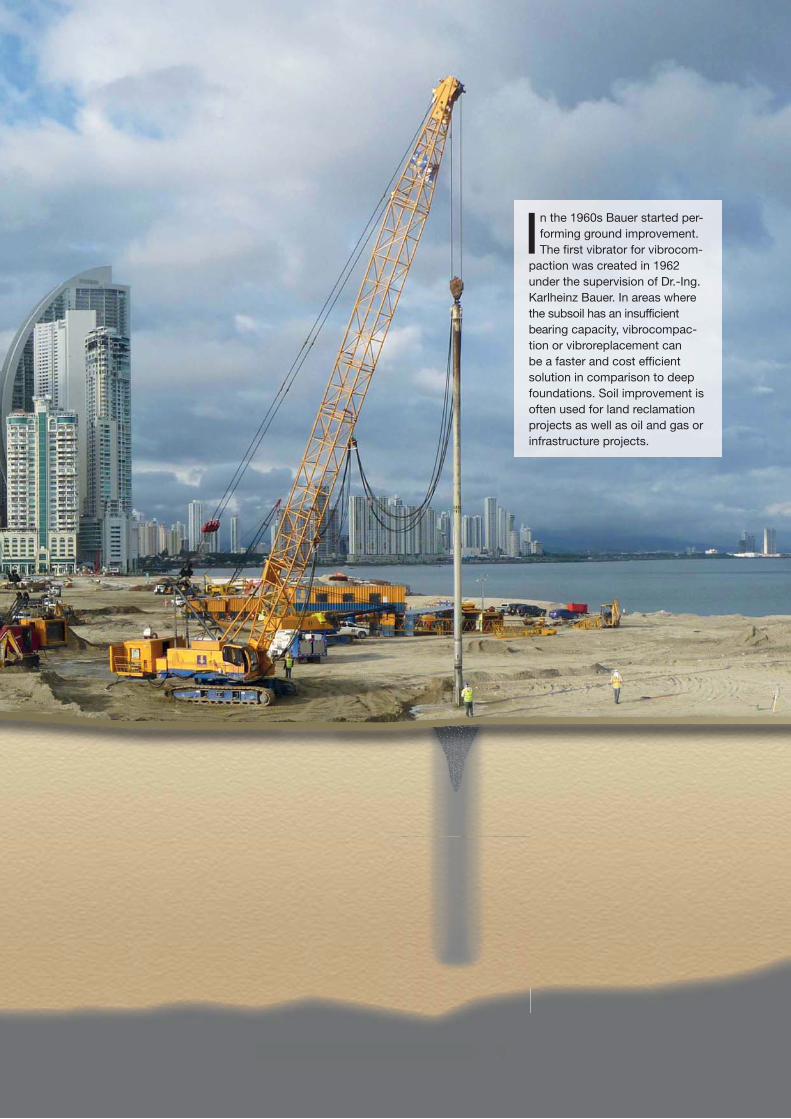
In the 1960s Bauer started per-forming ground improvement. The first vibrator for vibrocom-
paction was created in 1962 under the supervision of Dr.-Ing. Karlheinz Bauer. In areas wherethe subsoil has an insufficient bearing capacity, vibrocompac-tion or vibroreplacement can be a faster and cost efficient solution in comparison to deep foundations. Soil improvement is often used for land reclamation projects as well as oil and gas or infrastructure projects.

More than 45 years experience
Some of our highlight projects:
1962 Development and construction of the fi rst Bauer vibrator for vibrocompaction, based on a hydraulic driven engine
1971 Collini-Center, Mannheim, Germany Vibrocompaction up to a depth of 12 m
1975 Las Palmas, Grand Canary Vibrocompaction of 250,000 m³ of the so called “Picon” material (a volcanic slag)
1978 Thuwal, Kingdom of Saudi Arabia Vibrocompaction with 160,000 lin.m for a new harbor construction working from a ponton
2004 Palm Jumeirah, Dubai, UAE Soil improvement of the crown, 500,000 m² vibrocompaction
2005 Peribonka Dam, Canada Vibrocompaction of 700,000 m³ of the fi lls and partially the river deposits at the main dam base up to a depth of 35 m
2009 Cleveland Clinic, Al Sowah Island, Abu Dhabi, UAE Vibrocompaction of 90,000 m² to a depth of approximately 10 m
2012 Davao City, Philippines Vibrocompaction of 100,000 lin.m up to a depth of 18 m
Ocean Reef Island, Panama Vibrocompaction of 100,000 m² up to a depth of 15 m
1988 Cardiff, United Kingdom Installation of 24,000 lin.m of stone columns with a length of 9 m to 10 m for the ring road
1990 Singapore Securing of dams against settlement and shear failure by installing 230,000 lin.m of stone columns
1995 Vancouver, Canada Delta Port, vibrocompaction of 1.5 Mio. m³ of fi ll, working from a ponton to a depth of approximately 31 m
1999 Schleuse Hohenwarte, Germany 28,000 lin.m of vibrocompaction up to a depth of 30 m

5BAUER Soil Improvement
General
Vibrocompaction
Vibroreplacement
Clay Silt Sand Gravel Stone
100%
90%
80%
70%
60%
50%
40%
30%
20%
10%
0%
Va
lue
s o
f P
(%
), b
y W
eig
ht
Particle Size (mm)
The table shows which ground conditions suit vibrocompaction and which suit vibrodisplacement (stone columns)
planned construction. In addition, a mitigation of earthquake induced liquefaction can be obtained. In com-parison to piles or barrettes (which de-scribe columnar elements that transfer loads), the subsoil will be considered as an improved soil continuum.
During the movement of the vibrator the solid part of the matrix will be fl oated and afterwards compacted,
strength values ranging from 20 to 100 kN/m² by assembling compacted
Soil improvement is a special foun-dation technique to improve the soil characteristics such as the
relative density or Young’s modulus of elasticity. The technique is required in cases where the bearing capacity of the subsoil is not adequate for the
Applicable in non-cohesive soil with a maximum fi ne content of 10 % such as sands or gravels.
Applicable in mixed grained or cohe-sive soils, such as sandy silts to fi ne-grained soils with undrained shear
Bauer offers two different techniques:
• Vibrodisplacement to install stone columns and
• Vibrocompaction also known as vibrofl otation
with the result that the void ratio of the matrix decreases.
coarse grained backfi ll material (stone aggregates).
Matrix(loose material)
Matrix(dense material)
Flotation
Vibro Compaction
Vibrocompaction
Vibrodisplacement
0.001 0.01 0.1 1 10 100

BAUER Soil Improvement6
Why Soil Improvement?recommends possible types of foun-dation. Normally, the subsoil provides adequate bearing capacity without special foundation measures being required. If the geotechnical specia-list comes to the conclusion that the
During the planning stage of a construction project, a soil investigation is usually carried
out at the proposed site by a geo-technical specialist who assesses the bearing capacity of the subsoil and
In many cases, soil improvement offers an economical and fast method for improving the engineering characteristics of the prevailing subsoil.
Different subsoil conditions and possible foundation solutions
subsoil does not have suffi cient bea-ring capacity, various solutions are available, such as soil improvement or deep foundations.
• No excavation material, there-fore no cost impact resulting from transportation and no dealing with contaminated soils.
• Simple foundation conditions, similar to natural subsoils with an adequate bearing capacity. The technique is highly adaptable.
Advantages of Soil Improvement• In general, no groundwater low-
ering required during installation phase. Therefore no requirements for permits and no risk to adjacent buildings.
• Environmentally compatible by using only natural materials.
By providing high level technical supervision and workmanship throughout the project execution and understanding the interaction between subsoil and structure, it is possible to fulfi ll the design require-ments like increasing the bearing capacity and mitigating liquefac-tion.
Subsoil with
an adequate
bearing capacity
Improved subsoil
(by vibrocompaction
or vibroreplacement)
Subsoil with an
adequate bearing
capacity
Pile

7BAUER Soil Improvement
Techniques
process, the soil is „fl oated“ by a wa-ter or air fl ush, the vibrator sinks and a settlement depression is formed at surface level. This is fi lled with additional material. By extracting the vibrator in stages, a compacted zone 2-4 m diameter is created.
the surrounding soil. This creates a crushed rock or gravel column which improves the surrounding soil due to the higher rigidity of the additional installed material. The selection of
Granular or weakly cohesive sedi-ments (fi nes less than a maximum of 10 %) such as gravel or sand often have very uneven layer densities in their natural state. With vibrocom-paction the relative density can be increased up to around 80 %. In the
Using vibroreplacement technique, the added material is transported directly to the vibrator tip (bottom feed method), compacted by multiple displacement stages and pressed into
The upper meters of subsoil cannot be compacted effectively by the vibro-compaction technique only. These areas must be compacted by surface compaction techniques like rollers or similar.
the most suitable technique depends primarily on the ground conditions, the loads to be carried and the boundary conditions.
Vibrocompaction
Vibroreplacement

BAUER Soil Improvement8
Designimproved layers by using the theory of Priebe, which is common prac-tice all over the world. The following diagram (Priebe, 1995) gives you an impression of how to assess the so-
Regarding vibrocompaction we investigate the “improved” soil by fi eld tests such as CPTu or
SPT. In case of vibroreplacement we estimate the soil conditions of the
called improvement factor by a given friction angle of the stone column (φs), the area ratio and an assumed Poisson’s ratio of the soil (μB).
As an alternative for the assessment of the settlement it might be reason-able to use FE-Applications. The results can give you a better impres-sion of the behaviour of the stone column in different layers. Through FE-Calculations you can also assess the bulking effect in soft layers.
Imp
rove
me
nt
Fa
cto
r n
6
5
4
3
2
1
Area Ratio A/Ac
1 2 3 4 5 6 7 8 9 10
μB = 1/3
φs = 45,0°
φs = 42,5°
φs = 40,0°
φs = 37,5°
φs = 35,0°

9BAUER Soil Improvement
Testinginvestigate the success of soil im-provement, especially for vibrocompac-tion. The resulting graphs display for
of a soil improvement by vibrore-placement, a zone load test can be executed. In this case for example, a concrete plate will be manufactured, set in place to cover a number of stone columns and loaded in stages (dead
The execution of the so-called Cone Penetration Tests (CPT)is the most common practice to
The graphs of a CPT can be used to evaluate for example the soil type and the Young’s modulus. In addition, it is possible to assess the liquefac-tion mitigation due to soil improve-ment works. To prove the success
example the cone resistance against depth and friction ratio.
load test) or as an alternative you can use a kentledge test. The settlement during the different load stages will be recorded, so you receive the load settlement behaviour of the improved soil.
Load cellHydraulic jack
Reference beamDial gauge extensometers
Load dispatcher (e.g. timber mat)
Concrete block (kentledge)
Beam
Kentledge support
De
pth
[m
]
Cone Resistance qc [MPa]
0
5
10
15
20
25
0 5 10 15 20 25 30 35 40 45 50
Reinforced concrete test base

BAUER Soil Improvement10
TR 17
TR 75/TR 85
Head piece
with 2“ fl ushing
connection
Follower pipe
Joint
(Isolator)
Poker with wear
shield and fl ush
holes
R90
155
170
580Ø320
696
5850
5850
3000
945
2232
[115
]
Ø300
1885
0
700
7000
7000
1000
012
0030
01
900
Ø406
2907
0
Qualityproduction data for documentation purposes is also carried out by the B-Tronic system.By deploying our professional employ-ees on all our projects, Bauer guaran-tees the quality of the soil improvement works. Documentation and quality management happens in accordance to the rules of DIN EN ISO 9001.
Based on extensive experience Bauer uses methods, equipment and techniques which allow safe
execution of soil improvement pro-jects. All process-specifi c production data are monitored and displayed on the B-Tronic monitor inside the ope-rator cabin for quality purposes. Elec-tronic data acquisition of all relevant
The horizontal centrifugal forces of the deep vibrator are generated by a hydraulic motor and an oscillator inside the vibrator section. When de-ploying deep vibrators in conjunction
Equipment
with customized Bauer base ma-chines, the required hydraulic power can be provided by the base machine itself (BG, BF or MC) or by a separate hydraulic power pack, for example
the HD 460. Bauer uses two different vibrator types, the TR 17 and the TR 75/TR 85. The TR 17 can reach a penetration depth of up to 25 m and the TR 75/TR 85 up to 45 m.

11BAUER Soil Improvement
Projects Worldwide
For the „Palm“ the Emirate of Dubai builts a 7,000,000 m² artifi cial island off Jumeirah Beach to house hotels and luxury villas. Most of the area was compacted by 17 Bauer deep vibrators.
In the port of Balboa on the pacifi c coast of Pa-nama, Bauer Fundaciones Panama compacted some 15 hectare of newly reclaimed land down to a depth of 22 m. The improved ground is being utilized to extend the second largest container terminal in Latin America and will in future be ca-pable of withstanding all kinds of loads that such use demands.
In Abu Dhabi, on Al Sowah Island, the 90,000 m² Cleveland Clinic is under construction. Bauer deployed as many as ten TR 85 deep vibrators when carrying out vibrofl otation densifi cation to provide ground improvement of the 10 m thick alluvial sand layer.
In Schindellegi, Highend I to III, a housing estate at the hillside was constructed. For the necessary ground improvement 12,800 lin.m vibroreplace-ment (stone columns) were installed, comprising of 1,117 columns with a length of up to 12 m.
Palm Jumeirah, Dubai, UAE
Port of Balboa, Panama
Cleveland Clinic, Abu Dhabi, UAE
Highend I to III, Schindellegi, Switzerland

BAUER Spezialtiefbau GmbHBAUER - Strasse 186529 Schrobenhausen, GermanyTel.: + 49 8252 97- 0Fax: + 49 8252 [email protected]
905.
026.
2
5/2
014
http://www.bauer.de/en/bst/
http://www.youtube.com/BAUERGruppe