basics of ip video network design august 2015 · identifying these risks and designing solutions...
TRANSCRIPT
White Paper: Basics of IP Video Network Design
©2015 AMG Systems Ltd. All rights reserved. Page 1 of 10 WP_BIPV_03082015 v01
AMG Systems Ltd 3 The Omega Centre, Stratton Business Park, Biggleswade, Bedfordshire, SG18 8QB, UK www.amgsystems.com
White Paper: Basics of IP Video Network Design
Date: August 2015
Executive summary Video surveillance is used extensively in businesses around the world for crime prevention, to promote Health and Safety and help protect staff and customers. Security Systems Integrators and Consultants are experts in identifying these risks and designing solutions to cater for individual businesses’ needs. The past 15 years have seen changes in available technology from traditional analogue CCTV to IP and this whitepaper is an introductory guide to the basics of IP video networking and design, covering:
How the different elements of an IP Video system function
How these differ from analogue CCTV
How system design impacts network requirements
Which equipment can be utilised to ensure optimum performance and investment This White Paper is designed for those who have analogue CCTV knowledge and want to understand the basics of IP video system design.
The evolution of CCTV technology The introduction of DVRs initiated the transition to digital CCTV, replacing VCRs (Video Cassette Recorders) with digital media storage options such as Hard Disk Drives, CD, DVD and USB thumb drives. Whilst performance has continuously improved, the key elements and core technologies used in CCTV have largely remained unchanged – even with the progression to full digital IP video systems. In simplified terms, the key elements of a CCTV system are the same today as they have been for many years:
Image capture: the sensor in camera
Image processing: Improving image quality, such as WDR and Day/Night operation
Transmission: From the camera (over coax, CAT5e, fibre etc) to the Viewing/Recording platform
Display: Live and Playback images on workstations/monitors
Compression: Conversion from analogue to digital video & the removal of redundant information to c.5% of original size
Record: Store the video for future playback
Decompression: Conversion of compressed digital video into a format which can be viewed
Playback: Search and playback of recorded video
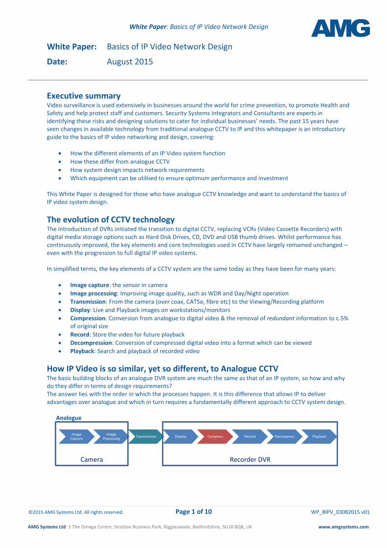
How IP Video is so similar, yet so different, to Analogue CCTV The basic building blocks of an analogue DVR system are much the same as that of an IP system, so how and why do they differ in terms of design requirements? The answer lies with the order in which the processes happen. It is this difference that allows IP to deliver advantages over analogue and which in turn requires a fundamentally different approach to CCTV system design.
Analogue
Image Capture
Image Processing
Transmission Display Compress Record Decompress Playback
Camera
Recorder DVR
White Paper: Basics of IP Video Network Design
©2015 AMG Systems Ltd. All rights reserved. Page 2 of 10 WP_BIPV_03082015 v01
AMG Systems Ltd 3 The Omega Centre, Stratton Business Park, Biggleswade, Bedfordshire, SG18 8QB, UK www.amgsystems.com
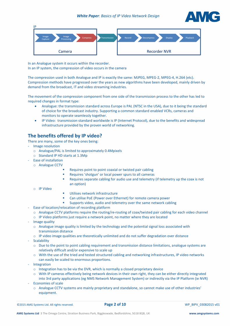
IP
In an Analogue system it occurs within the recorder. In an IP system, the compression of video occurs in the camera The compression used in both Analogue and IP is exactly the same: MJPEG, MPEG-2, MPEG-4, H.264 (etc). Compression methods have progressed over the years as new algorithms have been developed, mainly driven by demand from the broadcast, IT and video streaming industries. The movement of the compression component from one side of the transmission process to the other has led to required changes in format type:
Analogue: the transmission standard across Europe is PAL (NTSC in the USA), due to it being the standard of choice for the broadcast industry. Supporting a common standard enabled VCRs, cameras and monitors to operate seamlessly together.
IP Video: transmission standard worldwide is IP (Internet Protocol), due to the benefits and widespread infrastructure provided by the proven world of networking.
The benefits offered by IP video? There are many, some of the key ones being: - Image resolution
o Analogue/PAL is limited to approximately 0.4Mpixels o Standard IP HD starts at 1.3Mp
- Ease of installation o Analogue CCTV
Requires point to point coaxial or twisted pair cabling Requires ‘shotgun’ or local power spurs to all cameras Requires separate cabling for audio use and telemetry (if telemetry up the coax is not
an option) o IP Video
Utilises network infrastructure Can utilise PoE (Power over Ethernet) for remote camera power Supports video, audio and telemetry over the same network cabling
- Ease of location/relocation of recording platform o Analogue CCTV platforms require the routing/re-routing of coax/twisted pair cabling for each video channel o IP Video platforms just require a network point, no matter where they are located
- Image quality o Analogue image quality is limited by the technology and the potential signal loss associated with
transmission distance o IP video image qualities are theoretically unlimited and do not suffer degradation over distance
- Scalability o Due to the point to point cabling requirement and transmission distance limitations, analogue systems are
relatively difficult and/or expensive to scale up o With the use of the tried and tested structured cabling and networking infrastructures, IP video networks
can easily be scaled to enormous proportions. - Integration
o Integration has to be via the DVR, which is normally a closed proprietary device o With IP cameras effectively being network devices in their own right, they can be either directly integrated
into 3rd party applications (eg NMS Network Management System) or indirectly via the IP Platform (ie NVR) - Economies of scale
o Analogue CCTV systems are mainly proprietary and standalone, so cannot make use of other industries’ equipment.
Image Capture
Image Processing
Compress Transmission Record Decompress Display Playback
Camera
Recorder NVR
White Paper: Basics of IP Video Network Design
©2015 AMG Systems Ltd. All rights reserved. Page 3 of 10 WP_BIPV_03082015 v01
AMG Systems Ltd 3 The Omega Centre, Stratton Business Park, Biggleswade, Bedfordshire, SG18 8QB, UK www.amgsystems.com
o IP Video can reside on or, if located on a dedicated network, support applications/equipment from other manufacturers/industries – ultimately offering the potential to reduce costs
NB IP video is not the only technology that can support megapixel resolutions; HD-SDI (as used in the modern TV/movie/broadcast industry) and more recently HD-TVI (less susceptible to poor cable quality and supporting greater analogue cable distances), can offer megapixel quality images. However IP remains the dominant technological choice of end-users seeking the flexibility of image quality options and ease of installation for their commercial operations. As many end-users want to share CCTV information across their businesses, adoption of IP standards makes integration into their existing infrastructure a relatively simple process. There are some notable challenges in implementing an IP video system, to include:
Installation teams requiring a knowledge of IP networking
An understanding of the impact IP video streaming can have on available network bandwidth
An awareness of the impact resolution, frame rate and target image change/activity can have on required storage to achieve the required historical video data requirement.
However, with careful system design and appropriate product selection, these challenges can be managed and indeed utilised to encompass the benefits offered by IP video.
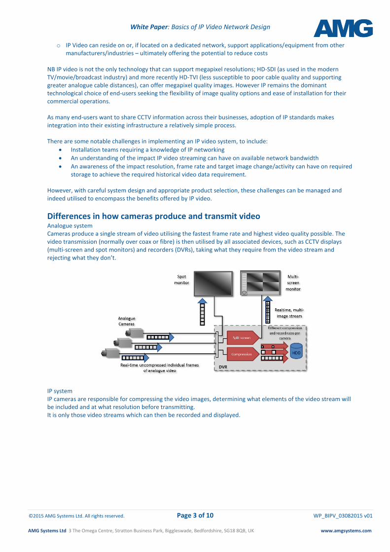
Differences in how cameras produce and transmit video Analogue system Cameras produce a single stream of video utilising the fastest frame rate and highest video quality possible. The video transmission (normally over coax or fibre) is then utilised by all associated devices, such as CCTV displays (multi-screen and spot monitors) and recorders (DVRs), taking what they require from the video stream and rejecting what they don’t.
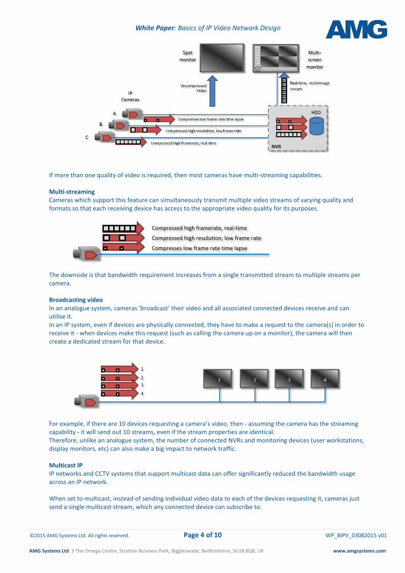
IP system IP cameras are responsible for compressing the video images, determining what elements of the video stream will be included and at what resolution before transmitting. It is only those video streams which can then be recorded and displayed.
White Paper: Basics of IP Video Network Design
©2015 AMG Systems Ltd. All rights reserved. Page 4 of 10 WP_BIPV_03082015 v01
AMG Systems Ltd 3 The Omega Centre, Stratton Business Park, Biggleswade, Bedfordshire, SG18 8QB, UK www.amgsystems.com
If more than one quality of video is required, then most cameras have multi-streaming capabilities. Multi-streaming Cameras which support this feature can simultaneously transmit multiple video streams of varying quality and formats so that each receiving device has access to the appropriate video quality for its purposes. The downside is that bandwidth requirement increases from a single transmitted stream to multiple streams per camera. Broadcasting video In an analogue system, cameras ‘broadcast’ their video and all associated connected devices receive and can utilise it. In an IP system, even if devices are physically connected, they have to make a request to the camera(s) in order to receive it - when devices make this request (such as calling the camera up on a monitor), the camera will then create a dedicated stream for that device.
For example, if there are 10 devices requesting a camera’s video, then - assuming the camera has the streaming capability - it will send out 10 streams, even if the stream properties are identical. Therefore, unlike an analogue system, the number of connected NVRs and monitoring devices (user workstations, display monitors, etc) can also make a big impact to network traffic. Multicast IP IP networks and CCTV systems that support multicast data can offer significantly reduced the bandwidth usage across an IP network. When set to multicast, instead of sending individual video data to each of the devices requesting it, cameras just send a single multicast stream, which any connected device can subscribe to.
C
Compressed high framerate, real-time Compressed high resolution, low frame rate
Compresses low frame rate time lapse
White Paper: Basics of IP Video Network Design
©2015 AMG Systems Ltd. All rights reserved. Page 5 of 10 WP_BIPV_03082015 v01
AMG Systems Ltd 3 The Omega Centre, Stratton Business Park, Biggleswade, Bedfordshire, SG18 8QB, UK www.amgsystems.com
To avoid potentially flooding a network (“Broadcast Storm”) with the varying quality streams from all cameras going to all devices on the network (including other cameras), the IP network needs to utilise network devices that support multicast data management, such as IGMP enabled layer 3 routers, IGMP snooping enabled layer 2 switches and sometimes by the VMS.
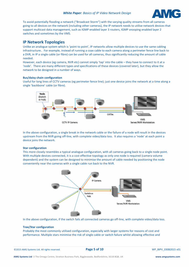
IP Network Topologies Unlike an analogue system which is ‘point to point’, IP networks allow multiple devices to use the same cabling infrastructure.. For example, instead of running a coax cable to each camera along a perimeter fence line back to a DVR, in IP a single cable (or fibre) can be used for all cameras, thus significantly reducing the amount of cable needed. However, each device (eg camera, NVR etc) cannot simply ‘tap’ into the cable – they have to connect to it at a ‘node’. There are many different types and specifications of these devices (covered later), but they allow the network to be designed in a number of ways. Bus/daisy chain configuration Useful for long lines of CCTV cameras (eg perimeter fence line); just one device joins the network at a time along a single ‘backbone’ cable (or fibre).
In the above configuration, a single break in the network cable or the failure of a node will result in the devices upstream from the NVR going off-line, with complete video/data loss. It also requires a ‘node’ at each point a device joins the network. Star configuration This more closely resembles a typical analogue configuration, with all cameras going back to a single node point. With multiple devices connected, it is a cost effective topology as only one node is required (camera volume dependent) and the system can be designed to minimise the amount of cable needed by positioning the node conveniently near the cameras with a single cable run back to the NVR.
In the above configuration, if the switch fails all connected cameras go off-line, with complete video/data loss. Tree/Star configuration Probably the most commonly utilised configuration, especially with larger systems for reasons of cost and performance. Multiple stars minimise the risk of single cable or switch failure whilst allowing effective and
White Paper: Basics of IP Video Network Design
©2015 AMG Systems Ltd. All rights reserved. Page 6 of 10 WP_BIPV_03082015 v01
AMG Systems Ltd 3 The Omega Centre, Stratton Business Park, Biggleswade, Bedfordshire, SG18 8QB, UK www.amgsystems.com
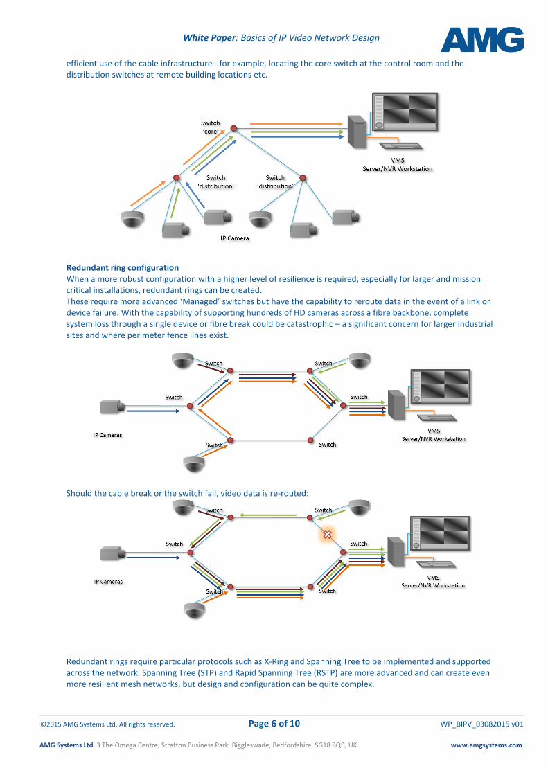
efficient use of the cable infrastructure - for example, locating the core switch at the control room and the distribution switches at remote building locations etc.
Redundant ring configuration When a more robust configuration with a higher level of resilience is required, especially for larger and mission critical installations, redundant rings can be created. These require more advanced ‘Managed’ switches but have the capability to reroute data in the event of a link or device failure. With the capability of supporting hundreds of HD cameras across a fibre backbone, complete system loss through a single device or fibre break could be catastrophic – a significant concern for larger industrial sites and where perimeter fence lines exist.
Should the cable break or the switch fail, video data is re-routed:
Redundant rings require particular protocols such as X-Ring and Spanning Tree to be implemented and supported across the network. Spanning Tree (STP) and Rapid Spanning Tree (RSTP) are more advanced and can create even more resilient mesh networks, but design and configuration can be quite complex.
White Paper: Basics of IP Video Network Design
©2015 AMG Systems Ltd. All rights reserved. Page 7 of 10 WP_BIPV_03082015 v01
AMG Systems Ltd 3 The Omega Centre, Stratton Business Park, Biggleswade, Bedfordshire, SG18 8QB, UK www.amgsystems.com
Network equipment A variety of network equipment types can be utilised in the creation of an IP network. Some of these network devices (hubs and switches in particular), sometimes referred to as ‘nodes’, accommodate the connection of edge devices such as cameras, PCs and printers. These network devices offer a range different functions and capabilities. They can vary considerably in performance and cost,however the correct selection will have a significant impact on performance of a CCTV system in terms of:
minimising latency of video transmission (ie the time it takes for a video stream to be displayed on a workstation monitor)
reducing overall bandwidth sent around the network
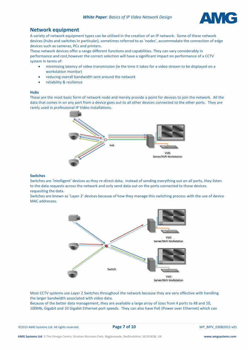
reliability & resilience Hubs These are the most basic form of network node and merely provide a point for devices to join the network. All the data that comes in on any port from a device goes out to all other devices connected to the other ports. They are rarely used in professional IP Video installations.
Switches Switches are ‘intelligent’ devices as they re-direct data; instead of sending everything out on all ports, they listen to the data requests across the network and only send data out on the ports connected to those devices requesting the data. Switches are known as ‘Layer 2’ devices because of how they manage this switching process with the use of device MAC addresses.
Most CCTV systems use Layer 2 Switches throughout the network because they are very effective with handling the larger bandwidth associated with video data. Because of the better data management, they are available a large array of sizes from 4 ports to 48 and 10, 100Mb, Gigabit and 10 Gigabit Ethernet port speeds. They can also have PoE (Power over Ethernet) which can
White Paper: Basics of IP Video Network Design
©2015 AMG Systems Ltd. All rights reserved. Page 8 of 10 WP_BIPV_03082015 v01
AMG Systems Ltd 3 The Omega Centre, Stratton Business Park, Biggleswade, Bedfordshire, SG18 8QB, UK www.amgsystems.com
support PoE enabled CCTV cameras and other devices (negating the need for local power) and ports capable of fibre transmission of Gigabit data over distances up to 100km. There are 2 main types of switch: unmanaged and managed, the latter providing many of the more advanced features required for effective network and bandwidth management, notably handling multicast video streams and supporting redundancy. Managed Switches For CCTV applications, managed switches have the following additional features:
Redundancy: providing features such as Spanning Tree and X-Ring protocol support
QoS (Quality of Service)
VLAN (Virtual Local Area Network) support
Port Mirroring
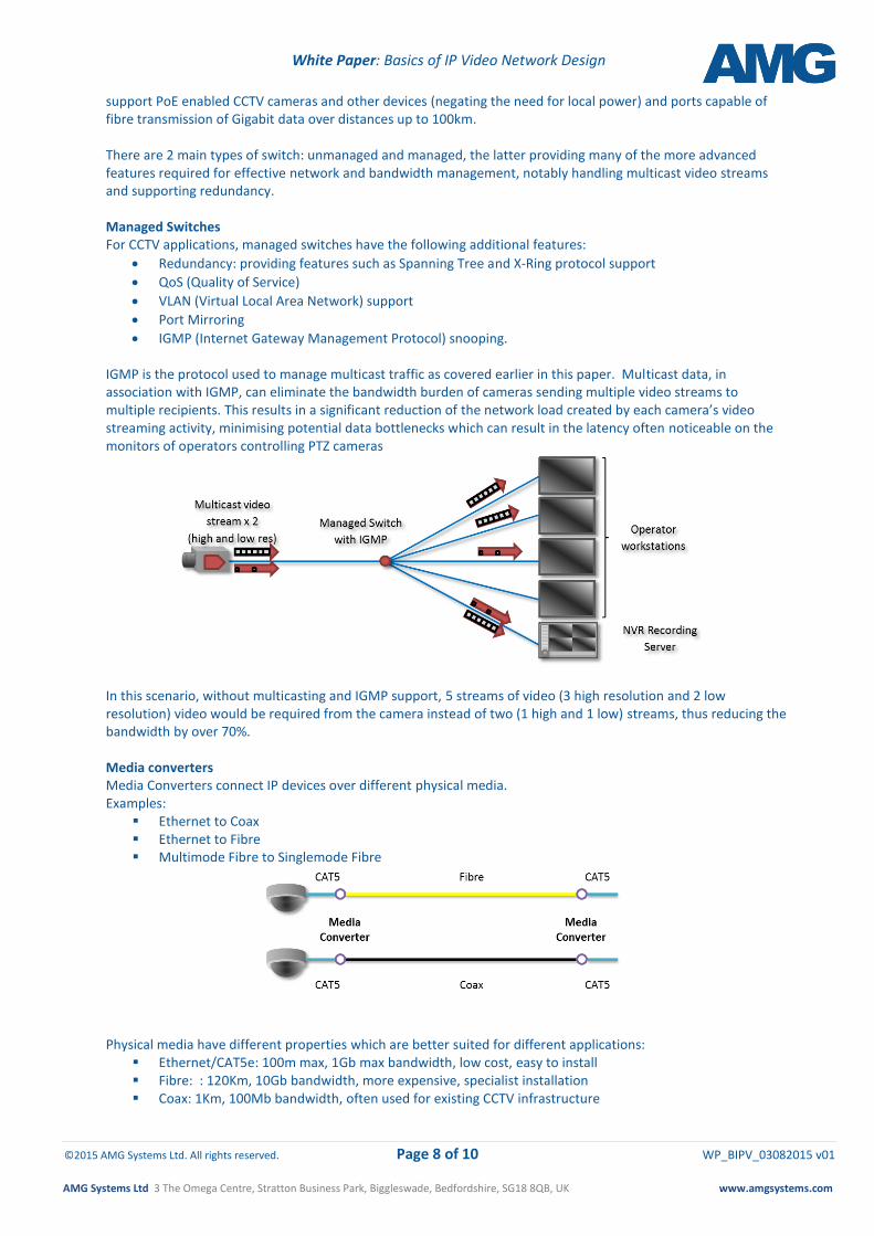
IGMP (Internet Gateway Management Protocol) snooping. IGMP is the protocol used to manage multicast traffic as covered earlier in this paper. Multicast data, in association with IGMP, can eliminate the bandwidth burden of cameras sending multiple video streams to multiple recipients. This results in a significant reduction of the network load created by each camera’s video streaming activity, minimising potential data bottlenecks which can result in the latency often noticeable on the monitors of operators controlling PTZ cameras
In this scenario, without multicasting and IGMP support, 5 streams of video (3 high resolution and 2 low resolution) video would be required from the camera instead of two (1 high and 1 low) streams, thus reducing the bandwidth by over 70%. Media converters Media Converters connect IP devices over different physical media. Examples:
Ethernet to Coax Ethernet to Fibre Multimode Fibre to Singlemode Fibre
Physical media have different properties which are better suited for different applications:
Ethernet/CAT5e: 100m max, 1Gb max bandwidth, low cost, easy to install Fibre: : 120Km, 10Gb bandwidth, more expensive, specialist installation Coax: 1Km, 100Mb bandwidth, often used for existing CCTV infrastructure
White Paper: Basics of IP Video Network Design
©2015 AMG Systems Ltd. All rights reserved. Page 9 of 10 WP_BIPV_03082015 v01
AMG Systems Ltd 3 The Omega Centre, Stratton Business Park, Biggleswade, Bedfordshire, SG18 8QB, UK www.amgsystems.com
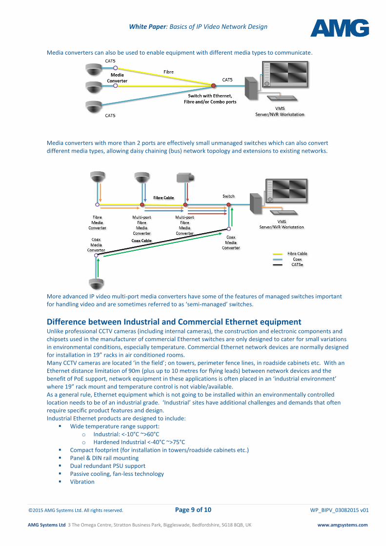
Media converters can also be used to enable equipment with different media types to communicate.
Media converters with more than 2 ports are effectively small unmanaged switches which can also convert different media types, allowing daisy chaining (bus) network topology and extensions to existing networks.
More advanced IP video multi-port media converters have some of the features of managed switches important for handling video and are sometimes referred to as ‘semi-managed’ switches.
Difference between Industrial and Commercial Ethernet equipment Unlike professional CCTV cameras (including internal cameras), the construction and electronic components and chipsets used in the manufacturer of commercial Ethernet switches are only designed to cater for small variations in environmental conditions, especially temperature. Commercial Ethernet network devices are normally designed for installation in 19” racks in air conditioned rooms. Many CCTV cameras are located ‘in the field’; on towers, perimeter fence lines, in roadside cabinets etc. With an Ethernet distance limitation of 90m (plus up to 10 metres for flying leads) between network devices and the benefit of PoE support, network equipment in these applications is often placed in an ‘industrial environment’ where 19” rack mount and temperature control is not viable/available. As a general rule, Ethernet equipment which is not going to be installed within an environmentally controlled location needs to be of an industrial grade. ‘Industrial’ sites have additional challenges and demands that often require specific product features and design. Industrial Ethernet products are designed to include:
Wide temperature range support: o Industrial: <-10°C ~>60°C o Hardened Industrial <-40°C ~>75°C
Compact footprint (for installation in towers/roadside cabinets etc.) Panel & DIN rail mounting Dual redundant PSU support Passive cooling, fan-less technology Vibration

White Paper: Basics of IP Video Network Design
©2015 AMG Systems Ltd. All rights reserved. Page 10 of 10 WP_BIPV_03082015 v01
AMG Systems Ltd 3 The Omega Centre, Stratton Business Park, Biggleswade, Bedfordshire, SG18 8QB, UK www.amgsystems.com
Summary IP networks offer some significant benefits over the limitations of analogue, including system scalability (both multi-site and multi-user support), HD camera resolution, ease of installation and a vast choice of compatible network equipment. The options and permutations available for systems design are enormous, enabling CCTV systems designers the flexibility to create more powerful and useable surveillance systems than ever before. However, they do need to be carefully designed to work effectively. Considerations for any new IP system design should include:
Considering camera and workstation locations – what is the best topology to minimise network equipment, cabling and bandwidth utilisation?
Quantity of cameras and workstations - how many video streams will be created, is multicast a requirement and, if so, how does this affect the choice of network topology?
Where are the cameras to be located? -Are Industrial grade devices required and would PoE reduce costs and increase reliability?
What are the real distances – with the 90m distance limitation between devices on CAT5e, is fibre a better choice?
Are there potentially single points of failure in the network design? Should redundancy be a consideration for at least part of the network?
For more information on how network design can help your CCTV system perform effectively, other white papers, training courses and details of our full Industrial Ethernet product range, please contact AMG Systems Ltd on +44 (0)1767 600 777 or email: [email protected]
Although the greatest care has been taken in the preparation and compilation of this white paper, no liability or responsibility of any kind (to extent permitted by law), including responsibility for negligence is accepted by AMG Systems Ltd. All information gathered is believed correct at August 2015. All corrections should be sent to AMG for future editions.