basics of drawing - style design · pdf filebasics of drawing id1-dfd-bd accuracy in drawing...
TRANSCRIPT
Basics of Drawing ID1-DFD-BD
Accuracy in Drawing
Drawing neatness and technique displayed
Ability to draw to scale
Ability to apply lineweights
Ability to write technical text
Tutorial notes and exercises.
During the course of the tutorial there are exercises that you will encounter. Each one of these exercises needs to be completed before you move onto the next section of work. At the end of each section there will be a cumulative assignment which uses all you new skills to complete. You will need to: * Draw basic shapes * Use drafting equipment * Understand lineweights * Understand how to set up a drawing on a page * How to apply scale to drawings * How to write technical text
This module aims to introduce you to Technical drawing. As an interior designer 2D technical drawings are crucial in conveying your designs to both your client but also the contractor working on the job. You will need to be able to produce working drawings that can be understood and built from. You will need to know the basics of drafting standards as a foundation before you endeavour to draw more complicated drawings such as plans and elevations. This module will introduce you to drafting equipment and how to construct a working drawing.
ID1-DFD-BD
Technical Drafting for Interior Design: This module acts as an introduction into technical drafting, specific to Interior Designers. It acts as a foundation or fundamentals course, teaching you the basic principles of technical drawing. If you feel you are skilled at technical drawing use this module as an opportunity to grow and move your skills towards refining you accuracy and technical ability. Technical drawing is an accurate and technical style of drawing and therefore has many rules which you will need to learn and adhere to. The first module is an introduction into the materials, techniques and theory behind drafting, thereafter the subject will become practical in nature. Limitations: Distance learning especially for a practical course comes with challenges. Not being able to attend actual lessons or have your tutor physically show you techniques and help you make corrections to your work, may seem like quite a set back initially. Don't let this aspect deter you from continuing, many correspondence art degrees exist online and are very successful. For the purposes of this module there are certain restrictions you need to adhere to in order to facilitate the process. > Keep your drawings/ art work to a maximum A3 size, this allows you to scan your work easily and then save as a JPEG. > You will be required to document your preliminary drawings in order to show authenticity. > Scanning of drawings will be a constant part of your process when submitting assignments. > Organizing your digital workspace and keeping proper files will assist you in meeting deadlines and submitting your work in the proper format. >The recommended materials are crucial in completing this module. >You will be required to complete exercises set during the course of the module as well as set assignments as per specific brief sheets.
Interior Design Visual Presentation, Maureen Mitton
Foundations of Interior Design, Susan J. Slotkis
Mastering Perspective, Santiago Arcas
Perspective for Interior Designers, John Pile
Architectural Drafting for Interior Designers, Lydia Cline
ID1-DFD-BD
Architectural drafting is pictorial images of buildings, interiors, details or other items which need to be built. These are different from other types of drawings as they are drawn to scale, include accurate measurements and detailed information, and other information necessary to build a structure. These documents are graphic representations to communicate how to do the construction. This comes in the form of drawings such as floor plans, elevations, sections, details, and ceiling plans. Types of Drawing: There are three categories of drawings in interior design: process drawings, (preliminary sketches, images and schematics), construction drawing, (drafted drawings, plans, elevations, sections, details etc), and presentation drawings, (illustrated sketches, three dimensional views, isometrics, axonometric etc). The focus of this module is drafted drawings, which focuses on conveying building details to the viewer. There are also three categories of Drafted drawings: Technical Sketch, Mechanical drawing and Computer aided drawing. Technical Sketching: Like an artist may use sketches to develop ideas for a painting or sculpture, technical sketches are used during the development of a design. The ability to make quick and accurate sketches is a valuable advantage that helps you convey design ideas to others. A sketch may be of an object, an idea of something you are thinking about, or a combination of both. Sketching is not always freehand and you may need to sketch on graph paper in order to take advantage of the lines squares. Technical sketches are drawn without mechanical aid, like a T-Square, compass, or straight edge but they are drawn to scale and contain a variety of lineweight and linestyles. A technical sketch gives an idea that the design is still being developed while a mechanical rafted or CAD drawing implies an advanced state of planning and gives the impression that the design has been finalised. Mechanical Drafting: Mechanical drafting is a refined style of drawing in which the pencil or pen is guided by devices such as T Squares, parallel rules, compasses, triangles and French Curves. These drawings are developed only after the conceptual phase of a project has been completed and the design finalised. However it is typical to see revisions of the construction documents as on site issues occur. The typical set of information required for construction include interior and exterior elevations, plans, sections and details. These are used within the professions of interior design, architecture, engineering and other building trade industries. Computer Drafting: When drafted documents are prepared on a computer, they are referred to as computer aided drafting or CAD. An advantage of CAD is the speed of revisions to a document. Instead of redrafting an entire page alterations can be made quickly and easily and the page reprinted or plotted. CAD drawings can also be easily stored electronically and sent to other designers for revisions or alterations. Some design and drafting work can be completed more quickly on CAD however you will still need to use technical or mechanical drafting for design development.
ID1-DFD-BD
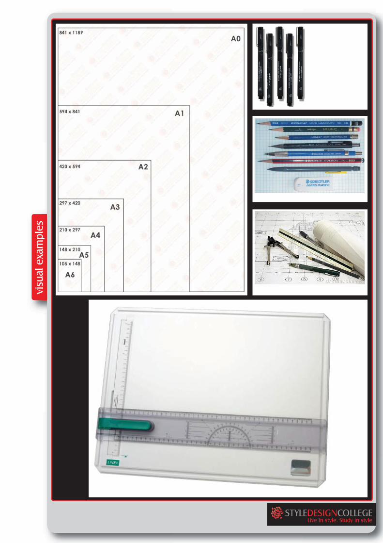
Drafting Equipment & Media: The papers and films used to draw on are drafting media. While sketching may be done on any size piece of paper or on a variety of types of paper, all form of architectural drafting, from technical sketching to mechanical drafting are done on standard sizes and types of paper. There are two main types of paper, tracing and vellum. Tracing Paper is a medium grade white transparent paper that takes pencil, ink and marker well. Trace is typically used for sketching and developing ideas, developing initial and preliminary layouts and developing space planning. It is an inexpensive paper and, since it is transparent, a new sheet can be placed over a preliminary drawing to refine it. Drafting Vellum is a high grade white transparent paper that takes pencil well and from which pencil lines can easily be erased. Reproductions can be made directly from pencil drawings on drafting vellum. Vellum also takes pen ink well, there are no bleed lines as the lines on vellum are crisp and solid. Care must be taken to avoid smearing the line while the ink is still drying. All paper used for technical drafting should be standard sizes based on the ISO method of paper sizing. Please refer to figure for the different sheet sixes. Technical Pens: Technical pens give you a precise and constant line with varying widths. Always be sure to replace the cap to avoid drying out or damage. Remember to pull your pen gently on the page and do not ever push the pen into the paper as this will cause blotting. Technical pens are available in the following sizes: 0,18mm, 0,25mm, 0.35mm, 0,5mm, 0,8mm and 1,0mm. Each pen gives a different lineweight which are used in specific instances. Pencils: Most draftsmen use sharp 2H and 4H pencils for drawing, as they are the hardest and produce the cleanest lines. Pencils may be wooden or mechanical pencils with replaceable leads. They utilize erasing shields and soft gum or nylon erasers to make corrections. Drawing Board: The drawing board is an essential tool. Paper will be attached and kept straight and still, so that the drawing can be done with accuracy. Various types of drafting machine may be attached to the board surface to assist the draftsperson. Parallel rules often span the entire width of the board and are so named because they remain parallel to the top edge of the board as they are moved up and down. Drafting machines use precalibrated scales and built in protractors to allow accurate drawing measurement.
ID1-DFD-BD
Set Square: The simplest form of set square is a triangular piece of transparent plastic with the centre removed. More commonly the set square combines this with a ruler and a half circle protractor. The outer edges are typically bevelled. These set squares come in two usual forms, both right triangles: one with 90-45-45 degree angles, the other with 30-60-90 degree angles. Combining the two forms by placing the hypotenuses together will also yield 15° and 75° angles. They are often purchased in packs with protractors and compasses. T-squares T-squares are used to draw straight lines. The head of the square, the cross member, is placed along the left edge or the top of the drafting table, while the square's blade is laid across the table's top, over the drawing paper. The drafter slides the square up, down or across on the tabletop, as required by a design, always keeping the flat side of the square flush with the tabletop's edge. This action keeps the square's blade parallel to the tabletop's edges. The drafter draws a horizontal line by resting the pencil's tip atop the square's blade, then pulling the pen right while maintaining a slight pressure against the blade. French Curves French curves are templates used to draw smooth curves. Before using this instrument, a drafter will produce, using other instruments such as a compass, a series of points that are to form a curve, such as a circle or portion of a circle. She'll use the French curve to connect these points with a smoothly flowing curve. To do this, she'll lay the instrument on the paper next to the points to be connected. She'll then attempt to pass the instrument's edge through each of the points. If the instrument doesn't initially fit the points, she'll rotate the instrument until it does. After completing this fitting process, she'll connect the points by resting her pencil tip atop the instrument, then pulling the pencil from the leftmost point to the rightmost.

ID1-DFD-BD
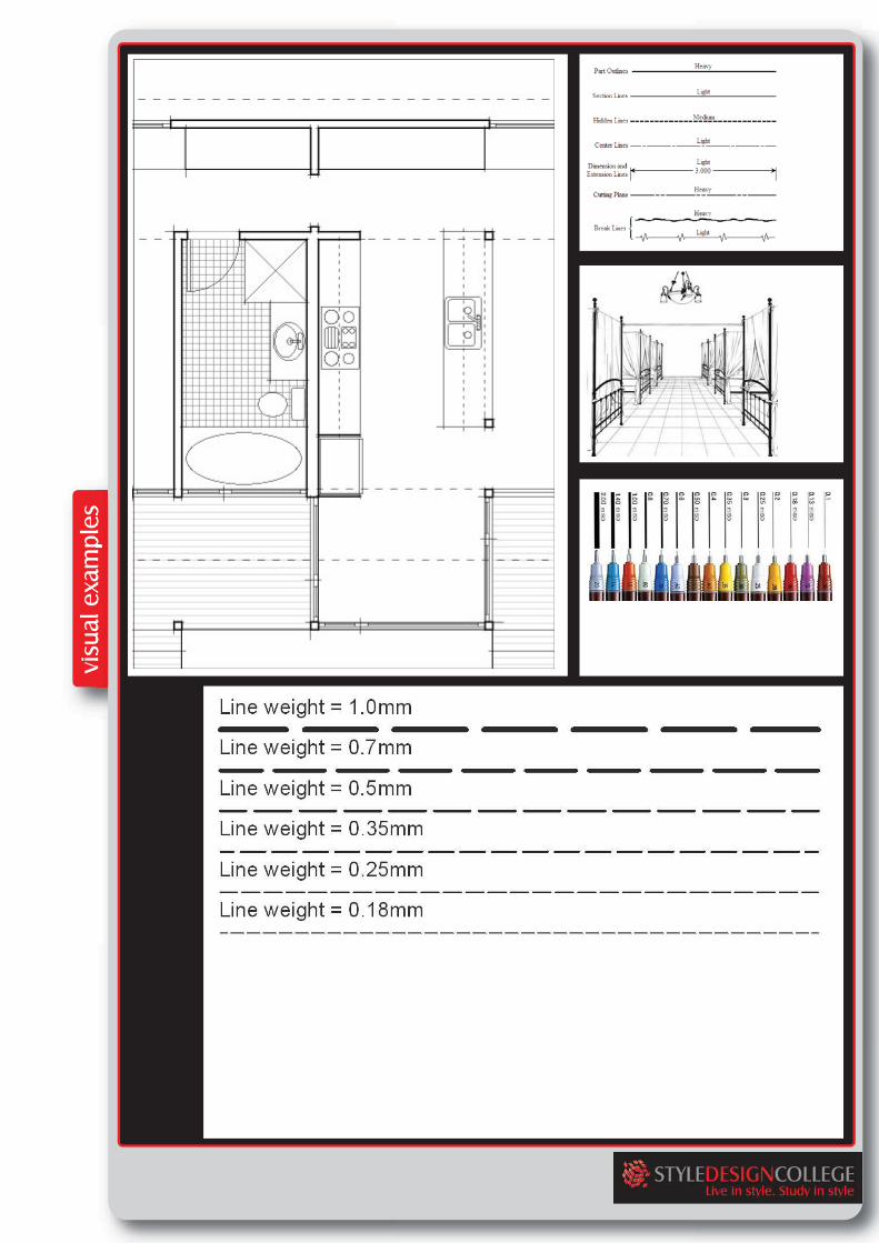
Lineweights: Lineweights and line quality are extremely important to a successful set of design drawings. All lines on the drawing must be clear, defined and dark so that copies can be made as required. The lineweight is the light or darkness and width of a line. Manual pencil drafting, drafting in ink or computer aided drafting must have a variety of line weights. Lineweights should vary from light, medium to dark on every drawing. All drawing must also be consistent in their lineweights which will give a sense of professionalism to the drawing, provide visual interest and ensure that it is easy to read and understand. All lines should be solid, uniform in width and consistent in darkness throughout their length. If a line drawing needs to be changed, make sure to erase it cleanly and recreate the line in appropriate line weight and quality. A drawing is usually drawn in light guidelines and then traced over with the appropriate pen in order to ensure the lines are as neat as possible. The best way to create consistent line weights and line quality is to keep your pencil or pen perpendicular to the drawing surface and keep a constant pressure as you draw from start to finish. Bear in mind the hardness or softness of the pencil to control the line weight, if the line seems either too light or too dark try varying the amount of pressure you place on the pencil as you draft. Construction Lines: (0.1mm pen or 4H pencil) Construction lines are initial lines that are drawn on the paper which act as guidelines. These lines are temporary and used to layout the page, create the initial shapes and provide a guide for lettering heights. The guidelines are to be very light and should be nearly invisible on the final drawing. Bold Lines: (0.5mm pen or 2B Pencil) The primary objects in a drawing should be created using a bold line. Bold lines are very dark and have a thick line Walls in plan view and the outline around the perimeter of an elevation are examples where bold lines should be used. Medium Lines: (0.3mm pen or HB pencil) Secondary objects such as doors, windows, furnishings should be drawn in a medium line weight. In elevation and 3D views, the perimeter of an object may be drawn in a bold line weight; however the information inside the object should be drawn in a medium weight. Light Lines: (0.18mm pen or 2H pencil) Action Lines, information Lines and fill patterns should be drawn with light lineweights. Action lines show the potential movement of an object such as a door swing in plan view. Information Lines convey information about a detail, often in the form of a note.

ID1-DFD-BD
Border lines: (.7mm pen or 4B pencil) Border Lines are used to create a margin on the drawing sheet and to create lines around the title block. Border lines should be as dark and about twice as thick as a bold line. Line Types: Along with line weight and quality there are standards for different types of lines. Each has a definite meaning and is recognised as a typical symbol or object within the building trades industry. Solid Line: Solid lines are used to indicate visible objects that can be seen in plan, elevation or 3D views. Solid lines are also used for leader lines and dimension lines. Dashed Lines: Hidden objects or edges are drawn with short dashed lines. These are used to show hidden parts of an object or objects below or behind another object. Dashed lines are also used to indicate shelving or cabinets above a counter. These lines should be in contact at corners and when perpendicular to another line. Leader Line: Leader lines are used to connect notes or references to objects or lines in a drawing. Leader lines start as a sold line and end in an arrow. Leader lines may be angled or curved. Break Lines: Break Lines are used when the extents of a drawing cannot fit on the size of the paper being used for the drawing. It can also be used when you only need to illustrate a portion of the design or drawing. Section Line: The section line is used to show a cutaway view of a floor plan. A section cutting all the way through a floor plan is referred to as a full section. The direction of the arrows shows the direction of the section view. The symbols on the end of the section line indicate the section number. Dimension Line: The dimension line is used to show the measurement of an object. It can be used to indicate length, width, diameter etc. The dimensions are listed in millimetres on all drawings.
ID1-DFD-BD
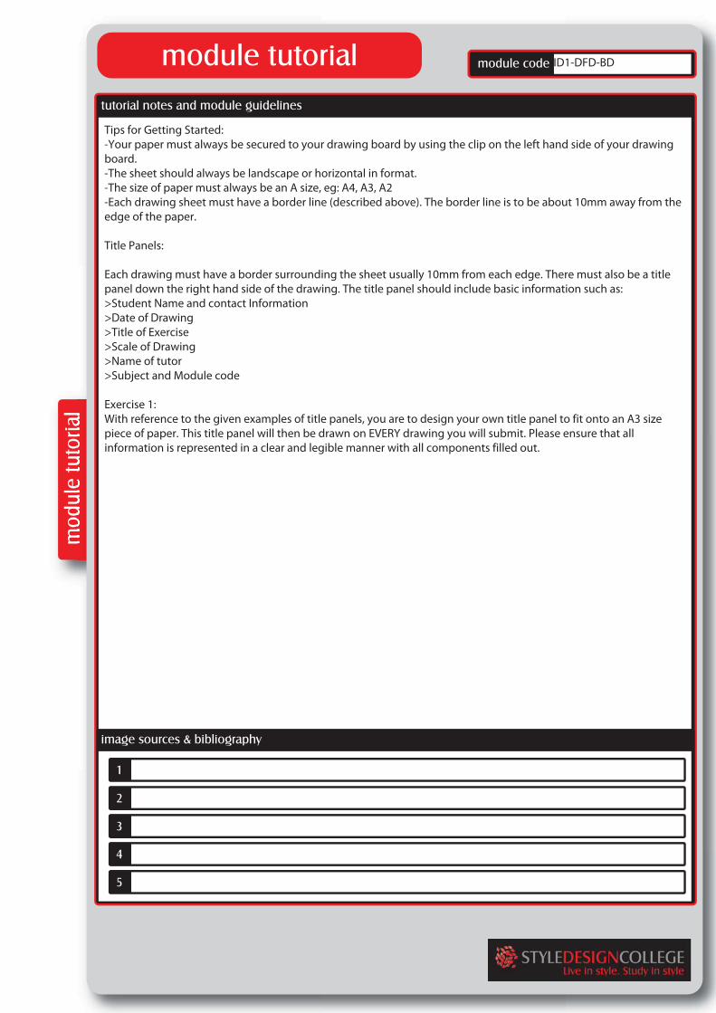
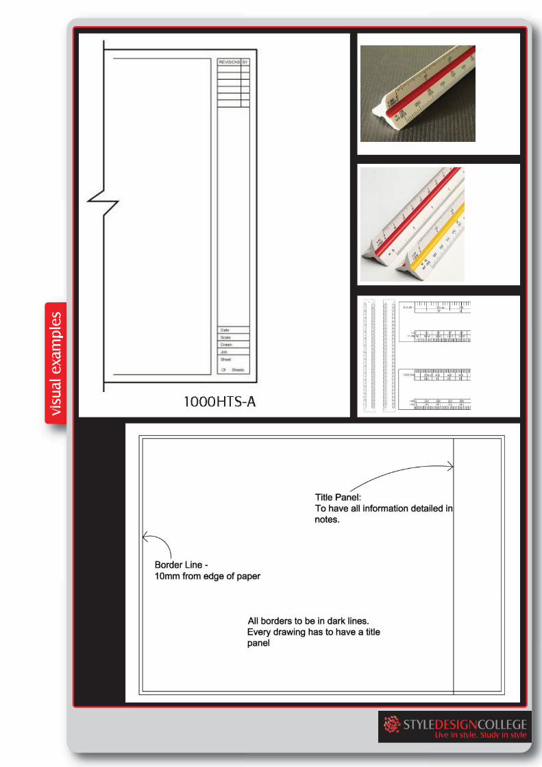
Tips for Getting Started: -Your paper must always be secured to your drawing board by using the clip on the left hand side of your drawing board. -The sheet should always be landscape or horizontal in format. -The size of paper must always be an A size, eg: A4, A3, A2 -Each drawing sheet must have a border line (described above). The border line is to be about 10mm away from the edge of the paper. Title Panels: Each drawing must have a border surrounding the sheet usually 10mm from each edge. There must also be a title panel down the right hand side of the drawing. The title panel should include basic information such as: >Student Name and contact Information >Date of Drawing >Title of Exercise >Scale of Drawing >Name of tutor >Subject and Module code Exercise 1: With reference to the given examples of title panels, you are to design your own title panel to fit onto an A3 size piece of paper. This title panel will then be drawn on EVERY drawing you will submit. Please ensure that all information is represented in a clear and legible manner with all components filled out.
ID1-DFD-BD
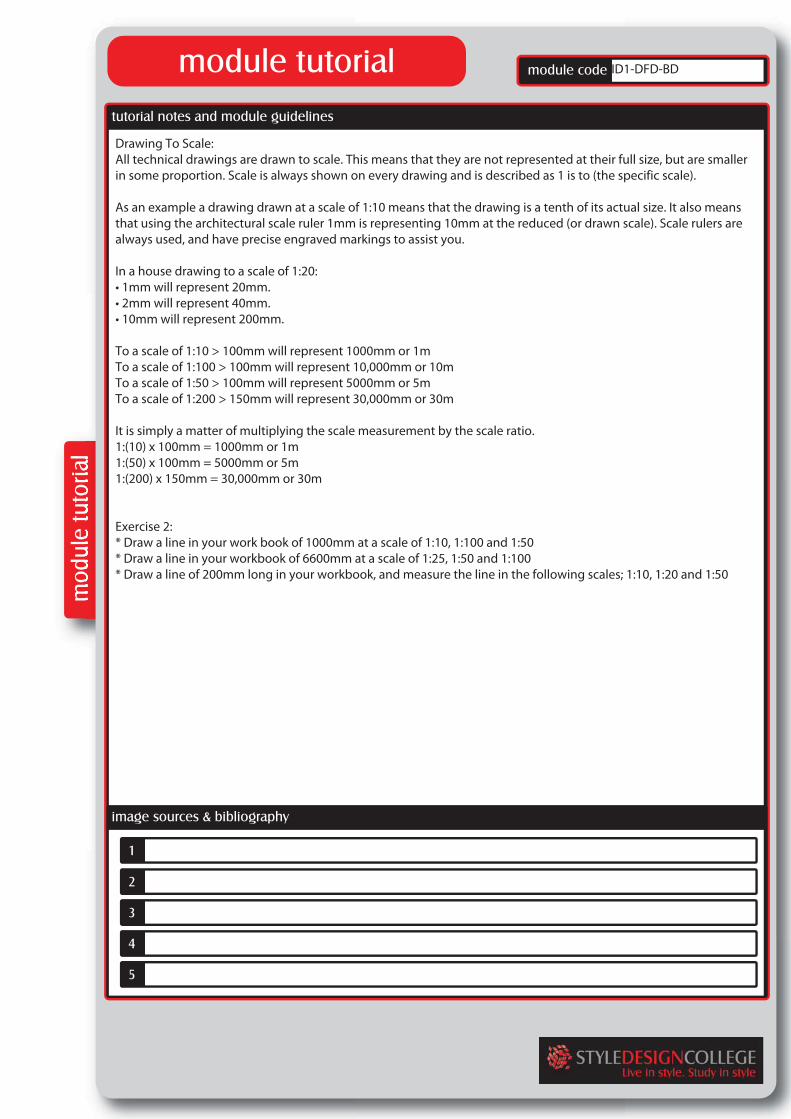
Drawing To Scale: All technical drawings are drawn to scale. This means that they are not represented at their full size, but are smaller in some proportion. Scale is always shown on every drawing and is described as 1 is to (the specific scale). As an example a drawing drawn at a scale of 1:10 means that the drawing is a tenth of its actual size. It also means that using the architectural scale ruler 1mm is representing 10mm at the reduced (or drawn scale). Scale rulers are always used, and have precise engraved markings to assist you. In a house drawing to a scale of 1:20: • 1mm will represent 20mm. • 2mm will represent 40mm. • 10mm will represent 200mm. To a scale of 1:10 > 100mm will represent 1000mm or 1m To a scale of 1:100 > 100mm will represent 10,000mm or 10m To a scale of 1:50 > 100mm will represent 5000mm or 5m To a scale of 1:200 > 150mm will represent 30,000mm or 30m It is simply a matter of multiplying the scale measurement by the scale ratio. 1:(10) x 100mm = 1000mm or 1m 1:(50) x 100mm = 5000mm or 5m 1:(200) x 150mm = 30,000mm or 30m Exercise 2: * Draw a line in your work book of 1000mm at a scale of 1:10, 1:100 and 1:50 * Draw a line in your workbook of 6600mm at a scale of 1:25, 1:50 and 1:100 * Draw a line of 200mm long in your workbook, and measure the line in the following scales; 1:10, 1:20 and 1:50
ID1-DFD-BD
Preliminary Drawings: Preliminary drawings are considered your rough work, which although are accurately constructed, they are in pencil on a lightweight paper. These initial drawings give you the opportunity to plan your final page layout ad determine how many drawings are needed for that project, and even which scales to use. Construction (or setting out lines) must be as light as possible to ensure you do not confuse construction lines with your final drawings. Final Drawings: Final drawings are always drafted in ink and on a better quality paper. Once all your preliminary drawings have been arranged, you can decide on the overall format, this will depend on the scale and amount of drawings or notes. The composition of a drawing is important, as it needs to be neat, accurate and logical. You will also need to allow space for notes and dimensions. You may place your preliminary drawing under your final drawing and trace, making sure you are only using technical pens.
ID1-DFD-BD
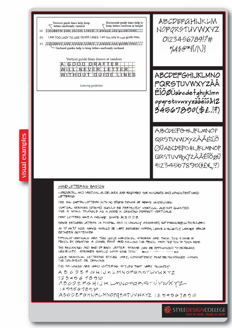
Hand Printed Text Hand printed text on a technical drawing needs to be neat, accurate and most importantly legible. Free hand lettering should be based on Roman Lettering without serifs. Each letter has to be carefully formed, with vertical lines remaining as upright as possible. Guidelines must be ruled in order to ensure that the test is straight and constant in height. The clear space between letters should be no less than twice their line thickness. The space between the words should be equal to that occupied by the letter "O" if touching both words. The space between sentences should be double that than between words. The height of letters and numerals is usually between 5 - 8mm for titles and between 2-4mm for general notes. Exercise 3: You are to practise your lettering by writing out: A B C D E F G H I J K L M N O P Q R S T U V W X Y Z and 0 1 2 3 4 5 6 7 8 9 in the following sizes: >2mm high (use 0.25 pen) >3mm high (use 0.25 pen) >4mm high (use 0.35 pen) >5mm high (use 0.35 pen) Remember to use your guidelines and only use uppercase lettering.