baldor dc servo motors and drives - steven engineering · dc servo motors baldor's dc servo...
TRANSCRIPT
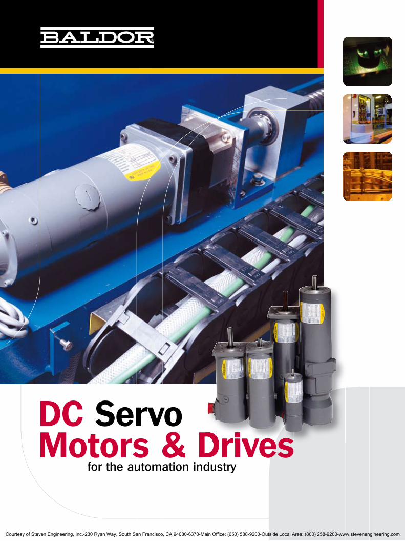
DC ServoMotors & Drives for the automation industryMotors & DrivesMotors & Drives
Courtesy of Steven Engineering, Inc.-230 Ryan Way, South San Francisco, CA 94080-6370-Main Office: (650) 588-9200-Outside Local Area: (800) 258-9200-www.stevenengineering.com
DC Servo Motors
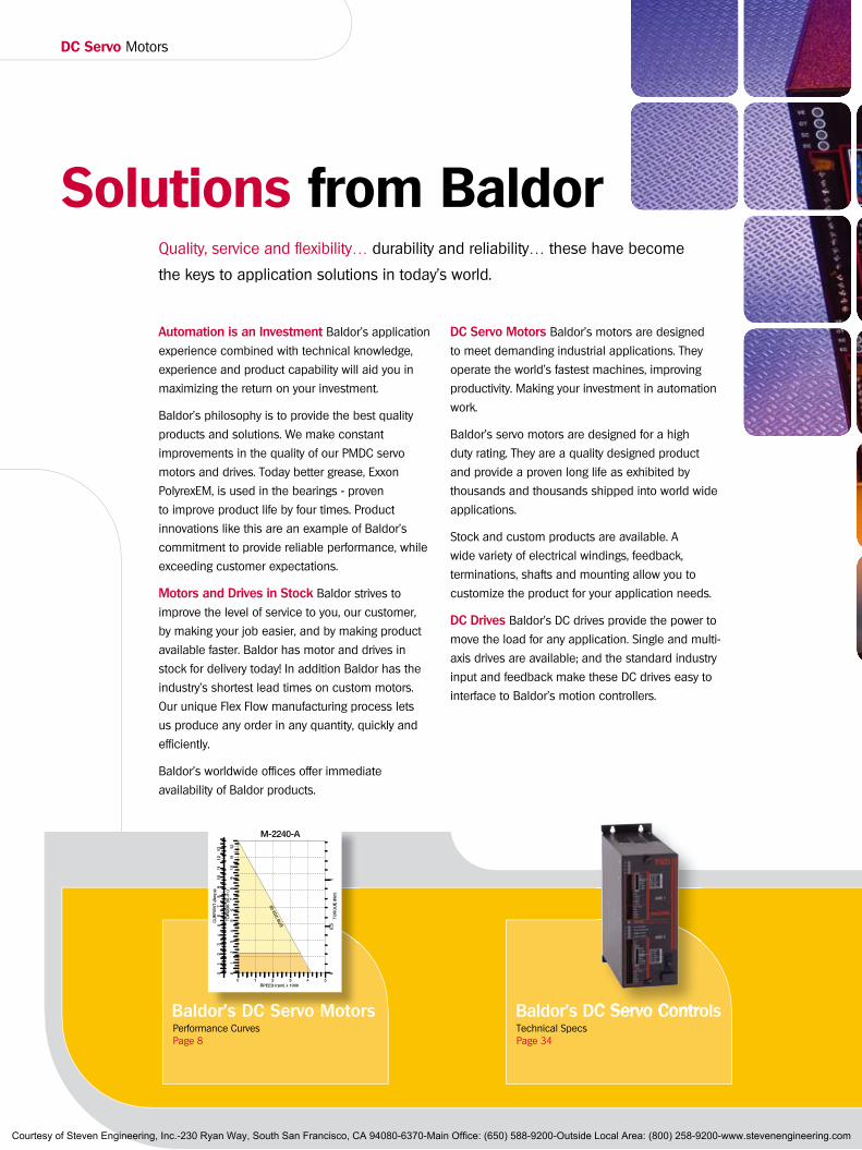
Baldor’s DC Servo ControlsPerformance CurvesPage 8
Technical SpecsPage 34
Baldor’s DC Servo Controls
Solutions from BaldorQuality, service and flexibility… durability and reliability… these have become
the keys to application solutions in today’s world.
Automation is an Investment Baldor’s application
experience combined with technical knowledge,
experience and product capability will aid you in
maximizing the return on your investment.
Baldor’s philosophy is to provide the best quality
products and solutions. We make constant
improvements in the quality of our PMDC servo
motors and drives. Today better grease, Exxon
PolyrexEM, is used in the bearings - proven
to improve product life by four times. Product
innovations like this are an example of Baldor’s
commitment to provide reliable performance, while
exceeding customer expectations.
Motors and Drives in Stock Baldor strives to
improve the level of service to you, our customer,
by making your job easier, and by making product
available faster. Baldor has motor and drives in
stock for delivery today! In addition Baldor has the
industry’s shortest lead times on custom motors.
Our unique Flex Flow manufacturing process lets
us produce any order in any quantity, quickly and
efficiently.
Baldor’s worldwide offices offer immediate
availability of Baldor products.
DC Servo Motors Baldor’s motors are designed
to meet demanding industrial applications. They
operate the world’s fastest machines, improving
productivity. Making your investment in automation
work.
Baldor’s servo motors are designed for a high
duty rating. They are a quality designed product
and provide a proven long life as exhibited by
thousands and thousands shipped into world wide
applications.
Stock and custom products are available. A
wide variety of electrical windings, feedback,
terminations, shafts and mounting allow you to
customize the product for your application needs.
DC Drives Baldor’s DC drives provide the power to
move the load for any application. Single and multi-
axis drives are available; and the standard industry
input and feedback make these DC drives easy to
interface to Baldor’s motion controllers.
Baldor’s DC Servo Motors
Courtesy of Steven Engineering, Inc.-230 Ryan Way, South San Francisco, CA 94080-6370-Main Office: (650) 588-9200-Outside Local Area: (800) 258-9200-www.stevenengineering.com
3
Courtesy of Steven Engineering, Inc.-230 Ryan Way, South San Francisco, CA 94080-6370-Main Office: (650) 588-9200-Outside Local Area: (800) 258-9200-www.stevenengineering.com
DC Servo Motors
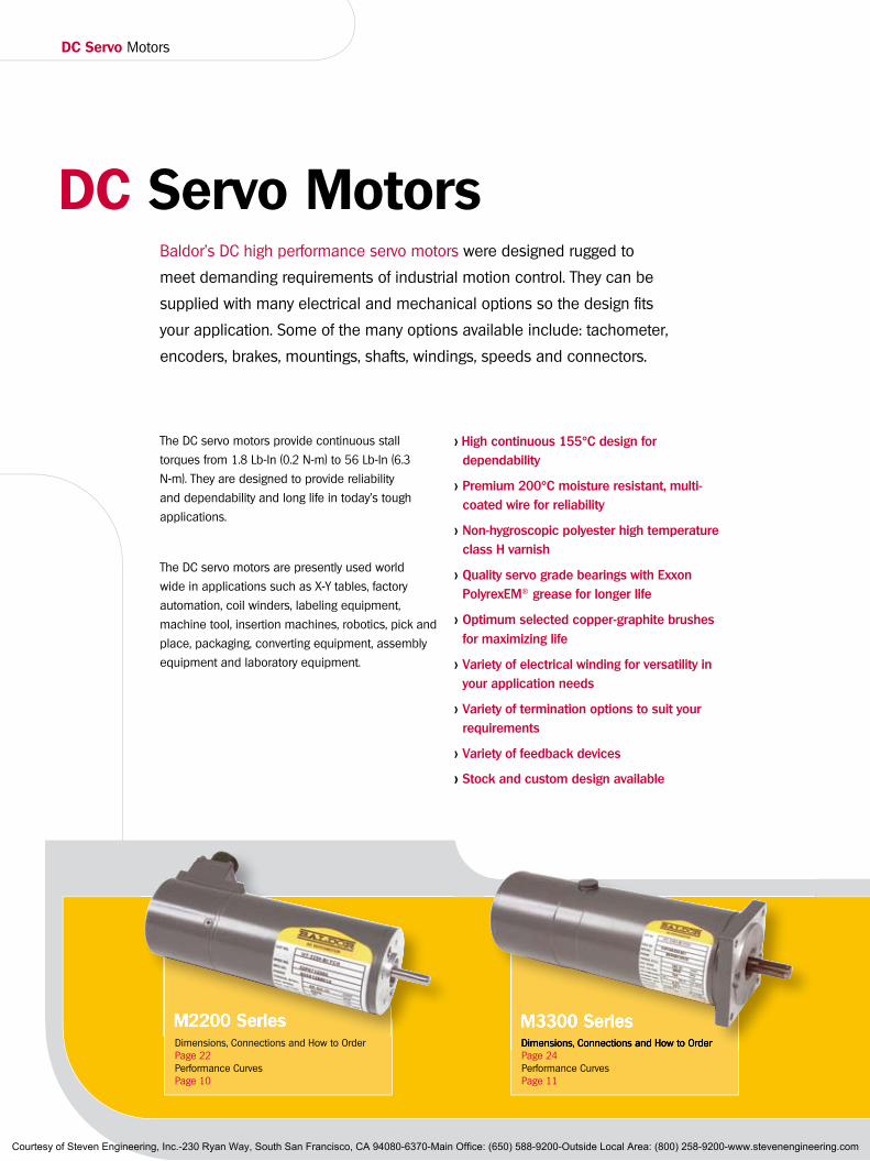
DC Servo MotorsBaldor's DC high performance servo motors were designed rugged to
meet demanding requirements of industrial motion control. They can be
supplied with many electrical and mechanical options so the design fits
your application. Some of the many options available include: tachometer,
encoders, brakes, mountings, shafts, windings, speeds and connectors.
The DC servo motors provide continuous stall
torques from 1.8 Lb-In (0.2 N-m) to 56 Lb-In (6.3
N-m). They are designed to provide reliability
and dependability and long life in today's tough
applications.
The DC servo motors are presently used world
wide in applications such as X-Y tables, factory
automation, coil winders, labeling equipment,
machine tool, insertion machines, robotics, pick and
place, packaging, converting equipment, assembly
equipment and laboratory equipment.
> High continuous 155°C design for dependability
> Premium 200°C moisture resistant, multi-coated wire for reliability
> Non-hygroscopic polyester high temperature class H varnish
> Quality servo grade bearings with Exxon PolyrexEM® grease for longer life
> Optimum selected copper-graphite brushes for maximizing life
> Variety of electrical winding for versatility in your application needs
> Variety of termination options to suit your requirements
> Variety of feedback devices
> Stock and custom design available
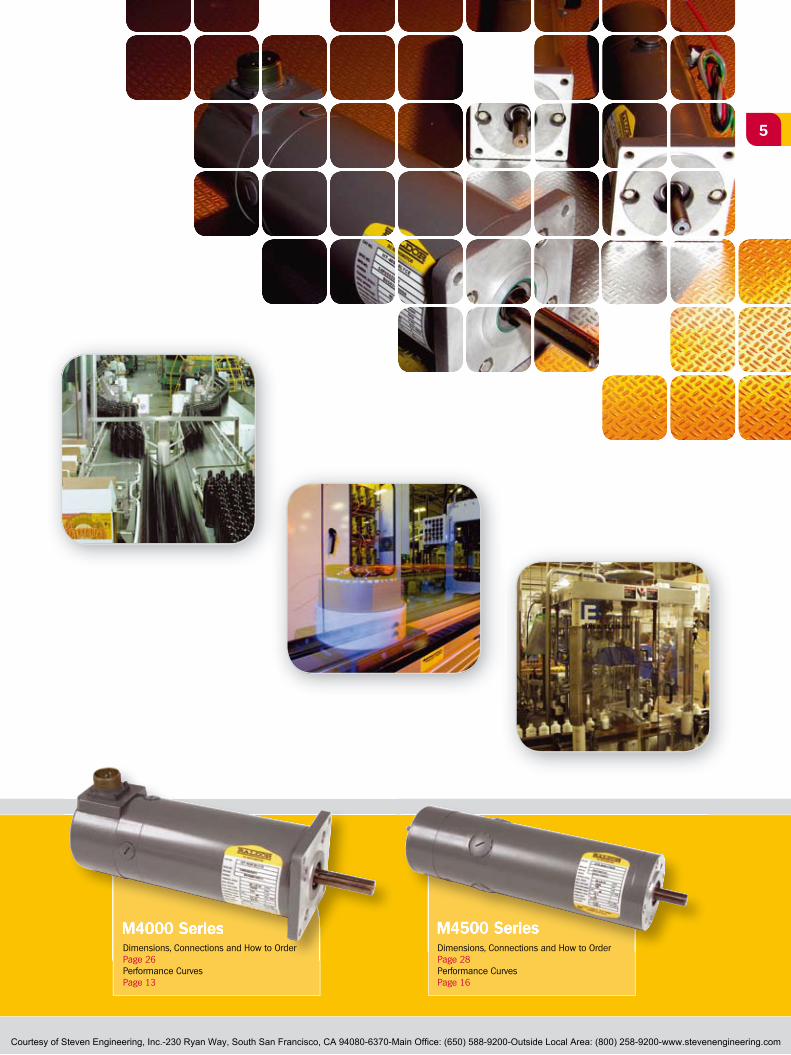
M3300 SeriesDimensions, Connections and How to OrderPage 22Performance CurvesPage 10
Dimensions, Connections and How to OrderPage 24Performance CurvesPage 11
M3300 SeriesDimensions, Connections and How to Order
M2200 SeriesM2200 Series
Courtesy of Steven Engineering, Inc.-230 Ryan Way, South San Francisco, CA 94080-6370-Main Office: (650) 588-9200-Outside Local Area: (800) 258-9200-www.stevenengineering.com
5
M4500 SeriesM4000 Series M4500 SeriesM4000 SeriesDimensions, Connections and How to OrderPage 26Performance CurvesPage 13
Dimensions, Connections and How to OrderPage 28Performance CurvesPage 16
Courtesy of Steven Engineering, Inc.-230 Ryan Way, South San Francisco, CA 94080-6370-Main Office: (650) 588-9200-Outside Local Area: (800) 258-9200-www.stevenengineering.com

DC Servo Motors
Baldor's DC Servo MotorsBaldor's DC servo motors are environmentally rugged,
providing reliability and long life in today's tough applications.
Rugged integral encoder - designed for industrial
applications
Variety of terminations - making it easy to adapt
into machines
Quality copper-graphite motor brushes - selected to provide
trouble free long life
Durable tachometer brushes - silver-graphite for low resistance and
accurate feedback
Precision wound tachometer - for low ripple feedback
Temperature stable tachometer magnets
- constant flux provides precision over wide range
Specification Description
Rating Continuous duty 155°C rotor temperature - high temperature design for dependability
Wire Premium 200°C moisture resistant, multi-coated copper wire for improved product reliability
InsulationNon-hygroscopic polyester high temperature Class H varnish - designed for dependability
Windings Variety of electrical windings - performance and versatility for your application needs
FeedbackPrecision integral tachometer with low ripple - precise speed regulation; integral encoder - for rugged industrial applications.
EnclosureTotally enclosed, non-ventilated housing, with optional environmental sealed to IP65 - provides protection in light industrial or demanding environments.
TerminationsStrain relieved cable exits; optional MS connectors, NPT hole, junction box - provides for variety of installation options making it easy to adapt to machines
Bearings Quality motor grade ball bearings - designed to handle radial and axial load ratings
Brushes Copper-graphite composition - selected for minimizing wear and maintenance intervals
MountingStandard mounting directly interchangeable with many machine tool manufacturers and PMDC motor and stepper manufacturers; optional NEMA and metric mounting - designed for worldwide acceptance
Courtesy of Steven Engineering, Inc.-230 Ryan Way, South San Francisco, CA 94080-6370-Main Office: (650) 588-9200-Outside Local Area: (800) 258-9200-www.stevenengineering.com
77
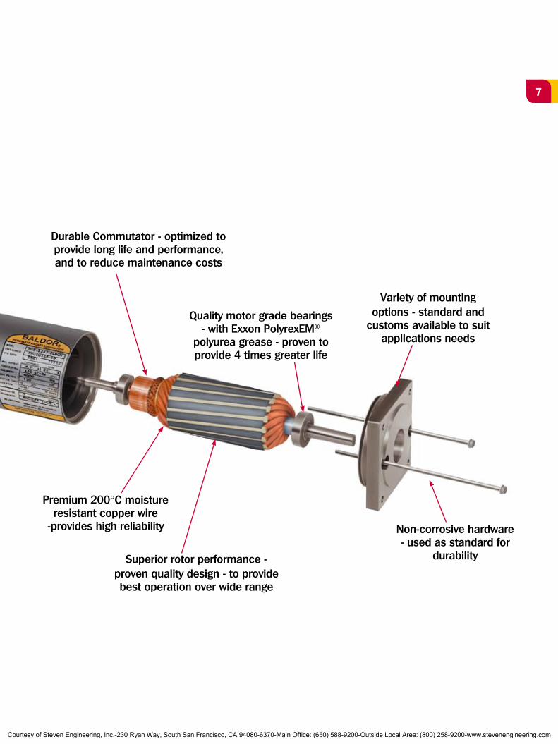
Premium 200°C moisture resistant copper wire
-provides high reliability
Durable Commutator - optimized to provide long life and performance, and to reduce maintenance costs
Superior rotor performance - proven quality design - to provide best operation over wide range
Quality motor grade bearings - with Exxon PolyrexEM®
polyurea grease - proven to provide 4 times greater life
Variety of mounting options - standard and
customs available to suit applications needs
Non-corrosive hardware - used as standard for
durability
Courtesy of Steven Engineering, Inc.-230 Ryan Way, South San Francisco, CA 94080-6370-Main Office: (650) 588-9200-Outside Local Area: (800) 258-9200-www.stevenengineering.com

DC Servo MotorsNextMove Motion control solutions
Baldor offers solutions for your motion control solutions…From speed and positioning, to operating the world’s
fastest machines - Baldor products are hard at work - they
increase productivity, improve quality, reduce cost. Baldor
motors are used worldwide in high performance industrial
motion control applications.
Baldor strives to provide the best value in industrial
electrical motors. That dedication shows in customer
preference for Baldor motors.
> DC Servo Motor Performance Selection GuideTorque
NominalVolts
MotorRPM
MotorInertia
Current Cont. at Stall Order
NumberCont. Stall Peak
lb-in Nm lb-in Nm lb-in-sec2 Kg-Cm2 Amp1.81.8
0.210.21
1313
1.41.4
5030
35003000
0.00030.0003
0.350.35
2.13.4
MT-2240-ACYANMT-2240-BCYAN
3.13.1
0.350.35
1919
2.12.1
5030
35003000
0.00050.0005
0.540.54
3.45.5
MT-2250-ACYANMT-2250-BCYAN
6.26.2
0.710.71
4444
4.94.9
10050
28002000
0.00160.0016
1.841.84
2.85.1
MT-3353-BLYANMT-3353-DLYAN
8.88.8
0.990.99
5959
6.76.7
100100
28005000
0.00240.0024
2.752.75
3.86
MT-3358-BLYANMT-3358-CLYAN
11.211.2
1.271.27
7575
8.58.5
100100
28004000
0.00330.0033
3.673.67
4.96.3
MT-3363-BLYANMT-3363-CLYAN
12.512.5
1.411.41
4545
5.05.0
100100
30004500
0.0070.007
7.917.91
5.57.9
MT-4050-ALYBEMT-4050-BLYBE
21.521.5
2.432.43
7272
8.18.1
100100
15002300
0.0110.011
12.4312.43
57
MT-4060-ALYBEMT-4060-BLYBE
2828
3.163.16
125125
14.114.1
100100
15002300
0.0140.014
15.8215.82
6.29.2
MT-4070-ALYBEMT-4070-BLYBE
4040
4.524.52
185185
20.920.9
100100
15002300
0.0240.024
27.1227.12
913
MT-4090-ALYBEMT-4090-BLYBE
303030
3.393.393.39
130130130
14.714.714.7
150150150
220032004400
0.0140.0140.014
15.8215.8215.82
6.19.212
MT-4525-BTYCNMT-4525-CTYCNMT-4525-DTYCN
40404040
4.524.524.524.52
190190190190
21.521.521.521.5
150150150150
1400220027004500
0.0210.0210.0210.021
23.7323.7323.7323.73
5.78.311.216.4
MT-4535-ATYCNMT-4535-BTYCNMT-4535-CTYCNMT-4535-DTYCN
505050
5.655.655.65
250250250
28.228.228.2
150150150
170023003300
0.0280.0280.028
31.6431.6431.64
810.615.7
MT-4545-ATYCNMT-4545-BTYCNMT-4545-CTYCN
585858
6.556.556.55
283283283
31.831.831.8
150150150
150021002900
0.0350.0350.035
39.5539.5539.55
8.512.115.3
MT-4555-ATYCNMT-4555-BTYCNMT-4555-CTYCN
Courtesy of Steven Engineering, Inc.-230 Ryan Way, South San Francisco, CA 94080-6370-Main Office: (650) 588-9200-Outside Local Area: (800) 258-9200-www.stevenengineering.com
9
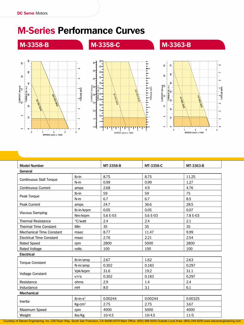
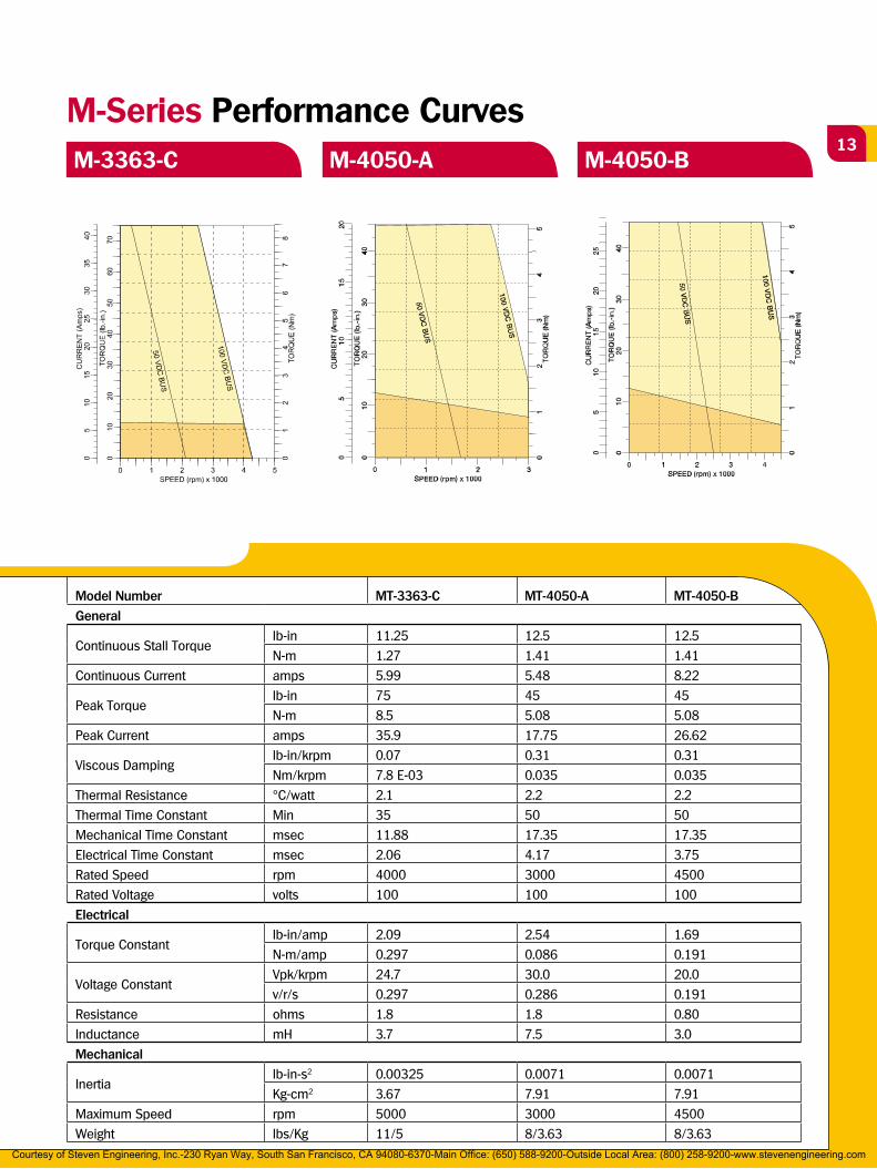
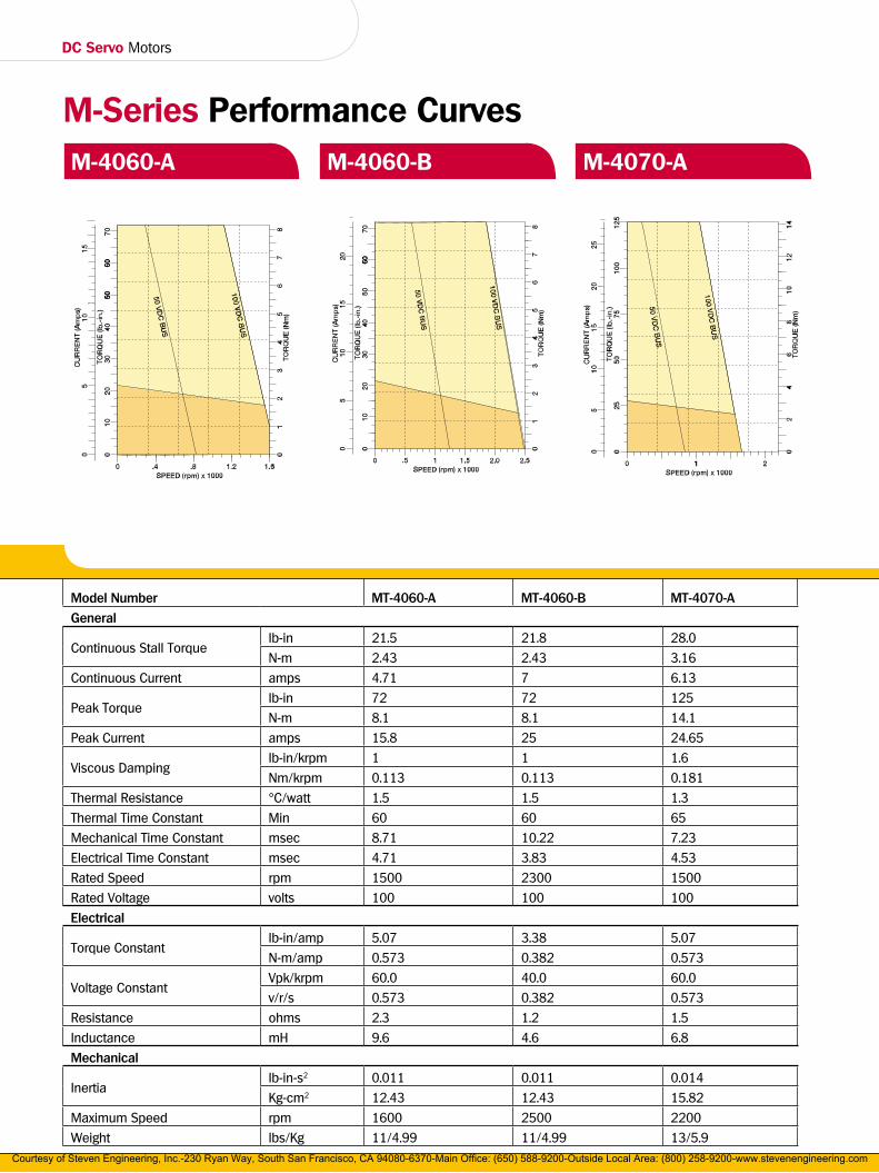
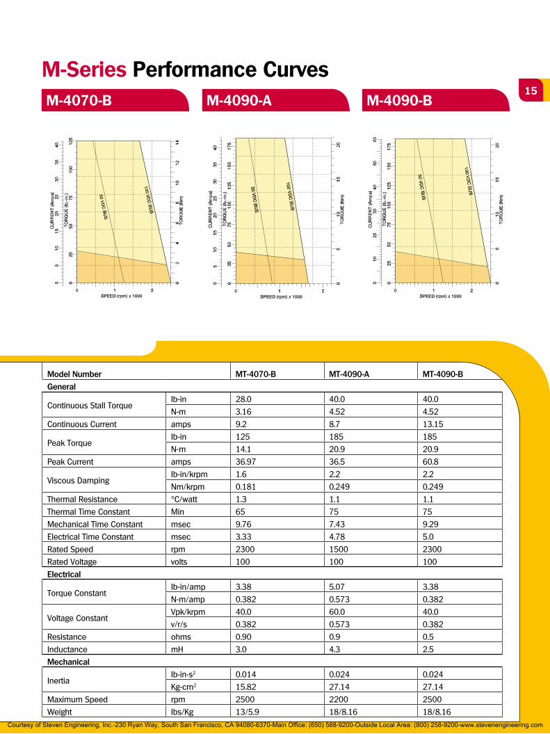
Baldor has provided the following curves in order to simplify the process of selecting both a motor and
control for a specific application. The following paragraphs explain how the information in these curves
should be interpreted.
In constant speed applications, motors are defined in terms of horsepower (which is torque at a base
speed). Servo motors normally operate over a wide speed range. The curves show continuous torque
(define as torque which will not overheat the motor), and peak torque (defined as intermittent acceleration
torque).
It is also necessary to know the current and voltage required for the motor to operate. The curves have a
scale that shows current required for any torque, and voltage required for any speed.
As an example, an application requires a continuous torque of 1.5 (0.17 Nm) lb-in at a speed of 1500 RPM.
The peak torque required for acceleration is 6 lb-in (0.67 Nm).
This curve shows that the M-2240-A will work in this application. The bus voltage required is 50VDC. The
continuous and peak currents required is 1.7 and 6.7 amps. From this information, we select a TSD control
(5 amps continuous, 10 amps peak) with a 115VAC input (50VDC Bus).
Speed – Torque Curves How to Read Motor Performance Curves
Peak current
capability of the motor
Peak current required
for the application
Continuous current
required for the
application
Required speed for
the application
Maximum speed
capability of the motor
Continuous torque
at speed for the
application
Intermittent Operations Area
Continuous Operations Area
Data in the tables have the following values: The motor's voltage constant (back-emf) and torque constant
are “cold” values (25°C); the continuous stall torque and current are “hot” values (155°C). The temperature
coefficient factor between “cold” and “hot” is 0.85 for DC motors.
Contact Baldor for special windings, custom shafts/mountings, and custom specs.
Continuous Torque
for the application
Peak Torque for the
application
Courtesy of Steven Engineering, Inc.-230 Ryan Way, South San Francisco, CA 94080-6370-Main Office: (650) 588-9200-Outside Local Area: (800) 258-9200-www.stevenengineering.com

DC Servo Motors
M-Series Performance CurvesM-2240-A M-2240-B M-2250-A
Model Number MT-2240-A MT-2240-B MT-2250-A
General
Continuous Stall Torquelb-in 1.88 1.88 3.13
N-m 0.21 0.21 0.35
Continuous Current amps 2.05 3.33 3.42
Peak Torquelb-in 13 13 19
N-m 1.4 1.4 2.1
Peak Current amps 12.3 20 18.5
Viscous Dampinglb-in/krpm 0.01 0.01 0.01
Nm/krpm 7.1 E-04 7.1 E-04 1.4 E-03
Thermal Resistance °C/watt 5 5 4.2
Thermal Time Constant Min 20 20 30
Mechanical Time Constant msec 2.0 2.0 9.5
Electrical Time Constant msec 7.8 9 2.52
Rated Speed rpm 3500 3000 3500
Rated Voltage volts 50 30 50
Electrical
Torque Constantlb-in/amp 1.012 0.625 1.0125
N-m/amp 0.115 0.071 0.115
Voltage ConstantVpk/krpm 12 7.4 12
v/r/s 0.115 0.071 0.115
Resistance ohms 4.0 1.6 2.3
Inductance mH 7.7 3.3 5.8
Mechanical
Inertialb-in-s2 0.00031 0.00031 0.00048
Kg-cm2 0.35 0.35 0.54
Maximum Speed rpm 5000 5000 5000
Weight lbs/Kg 3.2/1.5 3.2/1.5 3.5/1.6Courtesy of Steven Engineering, Inc.-230 Ryan Way, South San Francisco, CA 94080-6370-Main Office: (650) 588-9200-Outside Local Area: (800) 258-9200-www.stevenengineering.com
11
M-Series Performance CurvesM-2250-B M-3353-B M-3353-D
Model Number MT-2250-B MT-3353-B MT-3353-D
General
Continuous Stall Torquelb-in 3.13 6.25 6.25
N-m 0.35 0.71 0.71
Continuous Current amps 5.5 2.68 4.9
Peak Torquelb-in 19 44 44
N-m 2.1 4.94 4.94
Peak Current amps 30 16.9 34.4
Viscous Dampinglb-in/krpm 0.01 0.04 0.04
Nm/krpm 1.4 E-03 4.2 E-03 4.2 E-03
Thermal Resistance °C/watt 4.2 2.8 2.8
Thermal Time Constant Min 30 30 30
Mechanical Time Constant msec 9.8 11.96 12.99
Electrical Time Constant msec 2.78 2.77 2.22
Rated Speed rpm 3000 2800 2000
Rated Voltage volts 30 100 50
Electrical
Torque Constantlb-in/amp 0.625 2.59 1.41
N-m/amp 0.071 0.293 0.159
Voltage ConstantVpk/krpm 7.4 30.7 16.7
v/r/s 0.071 0.293 0.159
Resistance ohms 0.9 5.6 1.8
Inductance mH 2.5 15.5 4.0
Mechanical
Inertialb-in-s2 0.00048 0.00163 0.00163
Kg-cm2 0.54 1.84 1.84
Maximum Speed rpm 5000 4000 5000
Weight lbs/Kg 3.5/1.6 8/3.6 8/3.6Courtesy of Steven Engineering, Inc.-230 Ryan Way, South San Francisco, CA 94080-6370-Main Office: (650) 588-9200-Outside Local Area: (800) 258-9200-www.stevenengineering.com
DC Servo Motors
M-Series Performance CurvesM-3358-B M-3358-C M-3363-B
Model Number MT-3358-B MT-3358-C MT-3363-B
General
Continuous Stall Torquelb-in 8.75 8.75 11.25
N-m 0.99 0.99 1.27
Continuous Current amps 2.68 4.9 4.76
Peak Torquelb-in 59 59 75
N-m 6.7 6.7 8.5
Peak Current amps 24.7 36.6 28.5
Viscous Dampinglb-in/krpm 0.05 0.05 0.07
Nm/krpm 5.6 E-03 5.6 E-03 7.8 E-03
Thermal Resistance °C/watt 2.4 2.4 2.1
Thermal Time Constant MIn 35 35 35
Mechanical Time Constant msec 8.77 11.47 9.99
Electrical Time Constant msec 2.76 2.21 2.54
Rated Speed rpm 2800 5000 2800
Rated Voltage volts 100 100 100
Electrical
Torque Constantlb-in/amp 2.67 1.62 2.63
N-m/amp 0.302 0.183 0.297
Voltage ConstantVpk/krpm 31.6 19.2 31.1
v/r/s 0.302 0.183 0.297
Resistance ohms 2.9 1.4 2.4
Inductance mH 8.0 3.1 6.1
Mechanical
Inertialb-in-s2 0.00244 0.00244 0.00325
Kg-cm2 2.75 2.75 3.67
Maximum Speed rpm 4000 5000 4000
Weight lbs/Kg 10/4.5 10/4.5 11/5Courtesy of Steven Engineering, Inc.-230 Ryan Way, South San Francisco, CA 94080-6370-Main Office: (650) 588-9200-Outside Local Area: (800) 258-9200-www.stevenengineering.com
13
M-Series Performance CurvesM-3363-C M-4050-A M-4050-B
Model Number MT-3363-C MT-4050-A MT-4050-B
General
Continuous Stall Torquelb-in 11.25 12.5 12.5
N-m 1.27 1.41 1.41
Continuous Current amps 5.99 5.48 8.22
Peak Torquelb-in 75 45 45
N-m 8.5 5.08 5.08
Peak Current amps 35.9 17.75 26.62
Viscous Dampinglb-in/krpm 0.07 0.31 0.31
Nm/krpm 7.8 E-03 0.035 0.035
Thermal Resistance °C/watt 2.1 2.2 2.2
Thermal Time Constant Min 35 50 50
Mechanical Time Constant msec 11.88 17.35 17.35
Electrical Time Constant msec 2.06 4.17 3.75
Rated Speed rpm 4000 3000 4500
Rated Voltage volts 100 100 100
Electrical
Torque Constantlb-in/amp 2.09 2.54 1.69
N-m/amp 0.297 0.086 0.191
Voltage ConstantVpk/krpm 24.7 30.0 20.0
v/r/s 0.297 0.286 0.191
Resistance ohms 1.8 1.8 0.80
Inductance mH 3.7 7.5 3.0
Mechanical
Inertialb-in-s2 0.00325 0.0071 0.0071
Kg-cm2 3.67 7.91 7.91
Maximum Speed rpm 5000 3000 4500
Weight lbs/Kg 11/5 8/3.63 8/3.63Courtesy of Steven Engineering, Inc.-230 Ryan Way, South San Francisco, CA 94080-6370-Main Office: (650) 588-9200-Outside Local Area: (800) 258-9200-www.stevenengineering.com
DC Servo Motors
M-Series Performance CurvesM-4060-A M-4060-B M-4070-A
Model Number MT-4060-A MT-4060-B MT-4070-A
General
Continuous Stall Torquelb-in 21.5 21.8 28.0
N-m 2.43 2.43 3.16
Continuous Current amps 4.71 7 6.13
Peak Torquelb-in 72 72 125
N-m 8.1 8.1 14.1
Peak Current amps 15.8 25 24.65
Viscous Dampinglb-in/krpm 1 1 1.6
Nm/krpm 0.113 0.113 0.181
Thermal Resistance °C/watt 1.5 1.5 1.3
Thermal Time Constant Min 60 60 65
Mechanical Time Constant msec 8.71 10.22 7.23
Electrical Time Constant msec 4.71 3.83 4.53
Rated Speed rpm 1500 2300 1500
Rated Voltage volts 100 100 100
Electrical
Torque Constantlb-in/amp 5.07 3.38 5.07
N-m/amp 0.573 0.382 0.573
Voltage ConstantVpk/krpm 60.0 40.0 60.0
v/r/s 0.573 0.382 0.573
Resistance ohms 2.3 1.2 1.5
Inductance mH 9.6 4.6 6.8
Mechanical
Inertialb-in-s2 0.011 0.011 0.014
Kg-cm2 12.43 12.43 15.82
Maximum Speed rpm 1600 2500 2200
Weight lbs/Kg 11/4.99 11/4.99 13/5.9Courtesy of Steven Engineering, Inc.-230 Ryan Way, South San Francisco, CA 94080-6370-Main Office: (650) 588-9200-Outside Local Area: (800) 258-9200-www.stevenengineering.com
15
M-Series Performance CurvesM-4070-B M-4090-A M-4090-B
Model Number MT-4070-B MT-4090-A MT-4090-B
General
Continuous Stall Torquelb-in 28.0 40.0 40.0
N-m 3.16 4.52 4.52
Continuous Current amps 9.2 8.7 13.15
Peak Torquelb-in 125 185 185
N-m 14.1 20.9 20.9
Peak Current amps 36.97 36.5 60.8
Viscous Dampinglb-in/krpm 1.6 2.2 2.2
Nm/krpm 0.181 0.249 0.249
Thermal Resistance °C/watt 1.3 1.1 1.1
Thermal Time Constant Min 65 75 75
Mechanical Time Constant msec 9.76 7.43 9.29
Electrical Time Constant msec 3.33 4.78 5.0
Rated Speed rpm 2300 1500 2300
Rated Voltage volts 100 100 100
Electrical
Torque Constantlb-in/amp 3.38 5.07 3.38
N-m/amp 0.382 0.573 0.382
Voltage ConstantVpk/krpm 40.0 60.0 40.0
v/r/s 0.382 0.573 0.382
Resistance ohms 0.90 0.9 0.5
Inductance mH 3.0 4.3 2.5
Mechanical
Inertialb-in-s2 0.014 0.024 0.024
Kg-cm2 15.82 27.14 27.14
Maximum Speed rpm 2500 2200 2500
Weight lbs/Kg 13/5.9 18/8.16 18/8.16Courtesy of Steven Engineering, Inc.-230 Ryan Way, South San Francisco, CA 94080-6370-Main Office: (650) 588-9200-Outside Local Area: (800) 258-9200-www.stevenengineering.com
DC Servo Motors
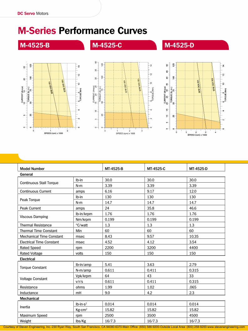
M-Series Performance CurvesM-4525-B M-4525-C M-4525-D
Model Number MT-4525-B MT-4525-C MT-4525-D
General
Continuous Stall Torquelb-in 30.0 30.0 30.0
N-m 3.39 3.39 3.39
Continuous Current amps 6.16 9.17 12.0
Peak Torquelb-in 130 130 130
N-m 14.7 14.7 14.7
Peak Current amps 24 35.8 46.6
Viscous Dampinglb-in/krpm 1.76 1.76 1.76
Nm/krpm 0.199 0.199 0.199
Thermal Resistance °C/watt 1.3 1.3 1.3
Thermal Time Constant Min 60 60 60
Mechanical Time Constant msec 8.43 9.57 10.35
Electrical Time Constant msec 4.52 4.12 3.54
Rated Speed rpm 2200 3200 4400
Rated Voltage volts 150 150 150
Electrical
Torque Constantlb-in/amp 5.41 3.63 2.79
N-m/amp 0.611 0.411 0.315
Voltage ConstantVpk/krpm 64 43 33
v/r/s 0.611 0.411 0.315
Resistance ohms 1.99 1.02 .065
Inductance mH 9.0 4.2 2.3
Mechanical
Inertialb-in-s2 0.014 0.014 0.014
Kg-cm2 15.82 15.82 15.82
Maximum Speed rpm 2500 3500 4500
Weight lbs/Kg 16/7.3 16/7.3 16/7.3Courtesy of Steven Engineering, Inc.-230 Ryan Way, South San Francisco, CA 94080-6370-Main Office: (650) 588-9200-Outside Local Area: (800) 258-9200-www.stevenengineering.com
17
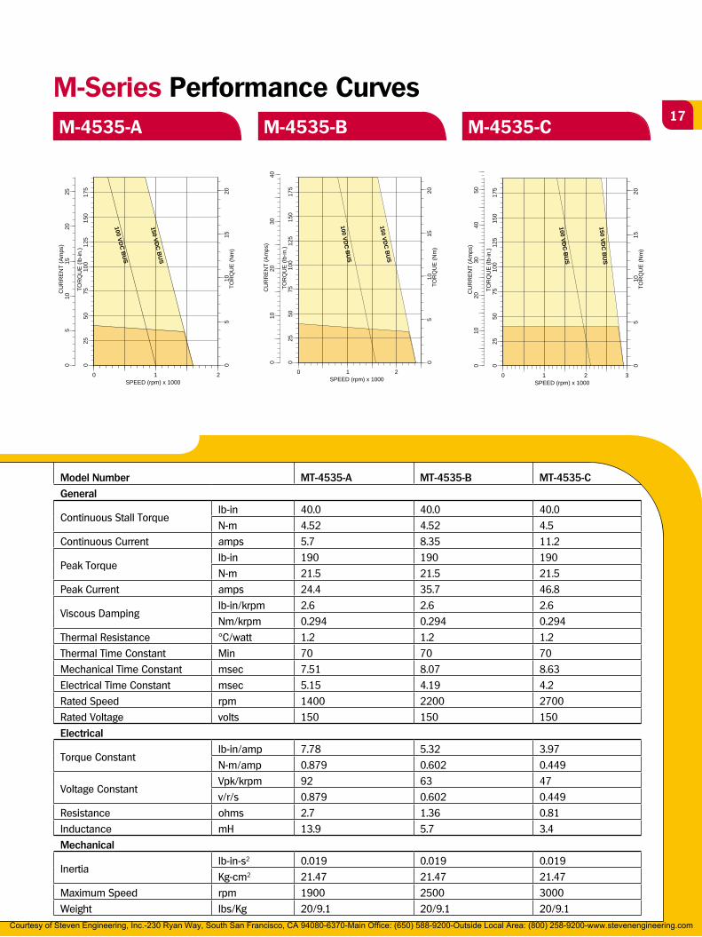
M-Series Performance CurvesM-4535-A M-4535-B M-4535-C
Model Number MT-4535-A MT-4535-B MT-4535-C
General
Continuous Stall Torquelb-in 40.0 40.0 40.0
N-m 4.52 4.52 4.5
Continuous Current amps 5.7 8.35 11.2
Peak Torquelb-in 190 190 190
N-m 21.5 21.5 21.5
Peak Current amps 24.4 35.7 46.8
Viscous Dampinglb-in/krpm 2.6 2.6 2.6
Nm/krpm 0.294 0.294 0.294
Thermal Resistance °C/watt 1.2 1.2 1.2
Thermal Time Constant Min 70 70 70
Mechanical Time Constant msec 7.51 8.07 8.63
Electrical Time Constant msec 5.15 4.19 4.2
Rated Speed rpm 1400 2200 2700
Rated Voltage volts 150 150 150
Electrical
Torque Constantlb-in/amp 7.78 5.32 3.97
N-m/amp 0.879 0.602 0.449
Voltage ConstantVpk/krpm 92 63 47
v/r/s 0.879 0.602 0.449
Resistance ohms 2.7 1.36 0.81
Inductance mH 13.9 5.7 3.4
Mechanical
Inertialb-in-s2 0.019 0.019 0.019
Kg-cm2 21.47 21.47 21.47
Maximum Speed rpm 1900 2500 3000
Weight lbs/Kg 20/9.1 20/9.1 20/9.1
CU
RR
EN
T (A
mps
)
TOR
QU
E (l
b-in
.)
1520
2510
5
M-4535-A
SPEED (rpm) x 1000
TOR
QU
E (N
m)
00
2510
012
515
017
550
75
05
1015
20
1 20
100 VDC
BU
S
150 VDC
BU
S
CU
RR
EN
T (A
mps
)
TOR
QU
E (l
b-in
.)
4030
2010
M-4535-B
SPEED (rpm) x 1000
TOR
QU
E (N
m)
00
2510
012
515
017
550
75
05
1015
20
1 20
100 VDC
BU
S
150 VDC
BU
S
CU
RR
EN
T (A
mps
)
TOR
QU
E (l
b-in
.)
4050
3020
10
M-4535-C
SPEED (rpm) x 1000
TOR
QU
E (N
m)
00
2510
012
515
017
550
75
05
1015
20
1 2 30
100 VDC
BU
S
150 VDC
BU
S
Courtesy of Steven Engineering, Inc.-230 Ryan Way, South San Francisco, CA 94080-6370-Main Office: (650) 588-9200-Outside Local Area: (800) 258-9200-www.stevenengineering.com
DC Servo Motors
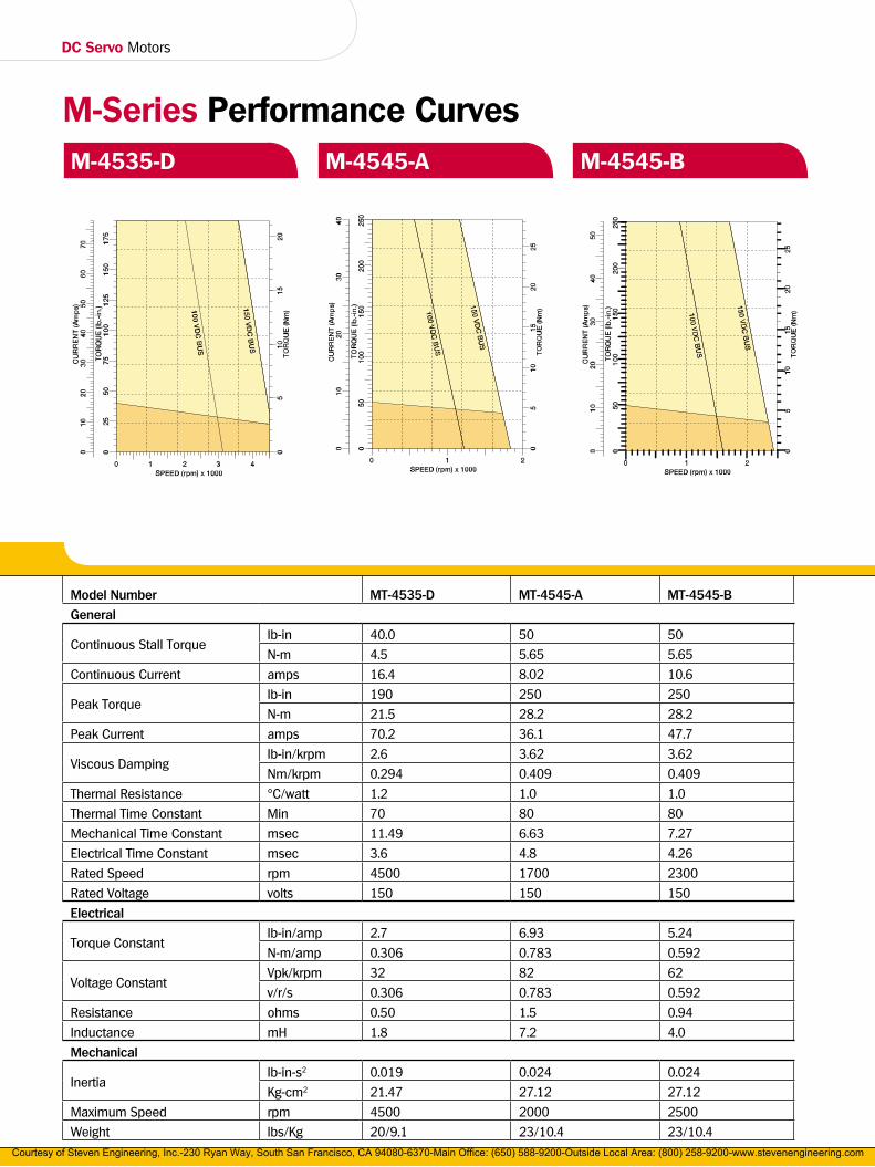
Model Number MT-4535-D MT-4545-A MT-4545-B
General
Continuous Stall Torquelb-in 40.0 50 50
N-m 4.5 5.65 5.65
Continuous Current amps 16.4 8.02 10.6
Peak Torquelb-in 190 250 250
N-m 21.5 28.2 28.2
Peak Current amps 70.2 36.1 47.7
Viscous Dampinglb-in/krpm 2.6 3.62 3.62
Nm/krpm 0.294 0.409 0.409
Thermal Resistance °C/watt 1.2 1.0 1.0
Thermal Time Constant Min 70 80 80
Mechanical Time Constant msec 11.49 6.63 7.27
Electrical Time Constant msec 3.6 4.8 4.26
Rated Speed rpm 4500 1700 2300
Rated Voltage volts 150 150 150
Electrical
Torque Constantlb-in/amp 2.7 6.93 5.24
N-m/amp 0.306 0.783 0.592
Voltage ConstantVpk/krpm 32 82 62
v/r/s 0.306 0.783 0.592
Resistance ohms 0.50 1.5 0.94
Inductance mH 1.8 7.2 4.0
Mechanical
Inertialb-in-s2 0.019 0.024 0.024
Kg-cm2 21.47 27.12 27.12
Maximum Speed rpm 4500 2000 2500
Weight lbs/Kg 20/9.1 23/10.4 23/10.4
M-Series Performance CurvesM-4535-D M-4545-A M-4545-B
Courtesy of Steven Engineering, Inc.-230 Ryan Way, South San Francisco, CA 94080-6370-Main Office: (650) 588-9200-Outside Local Area: (800) 258-9200-www.stevenengineering.com

19
M-Series Performance CurvesM-4545-C M-4555-A M-4555-B
Model Number MT-4545-C MT-4555-A MT-4555-B
General
Continuous Stall Torquelb-in 50 56.0 56.0
N-m 5.65 6.33 6.33
Continuous Current amps 15.7 8.47 10.9
Peak Torquelb-in 250 282 282
N-m 28.2 31.9 31.9
Peak Current amps 70 38.1 48.8
Viscous Dampinglb-in/krpm 3.62 3.71 3.71
Nm/krpm 0.409 0.413 0.419
Thermal Resistance °C/watt 1.0 0.9 0.9
Thermal Time Constant Min 80 90 90
Mechanical Time Constant msec 9.44 7.9 7.9
Electrical Time Constant msec 3.21 5.9 6.5
Rated Speed rpm 3300 1500 2100
Rated Voltage volts 150 150 150
Electrical
Torque Constantlb-in/amp 3.55 7.61 5.32
N-m/amp 0.401 0.859 0.602
Voltage ConstantVpk/krpm 42 90 63
v/r/s 0.401 0.859 0.602
Resistance ohms 0.56 1.52 0.6229
Inductance mH 1.8 7.9 3.8
Mechanical
Inertialb-in-s2 0.024 0.035 0.035
Kg-cm2 27.12 35.03 35.03
Maximum Speed rpm 3500 1900 2200
Weight lbs/Kg 23/10.4 27/12.2 27/12.2
CU
RR
EN
T (A
mps
)
TOR
QU
E (l
b-in
.)
3020
10
M-4555-A
SPEED (rpm) x 1000
TOR
QU
E (N
m)
00
100
150
200
50
05
1015
2025
1 20
100 VDC
BU
S
150 VDC
BU
S
CU
RR
EN
T (A
mps
)
TOR
QU
E (l
b-in
.)3040
2010
M-4555-B
SPEED (rpm) x 1000
TOR
QU
E (N
m)
00
100
150
200
50
05
1015
2025
1 20
100 VDC
BU
S
150 VDC
BU
S
Courtesy of Steven Engineering, Inc.-230 Ryan Way, South San Francisco, CA 94080-6370-Main Office: (650) 588-9200-Outside Local Area: (800) 258-9200-www.stevenengineering.com
DC Servo Motors
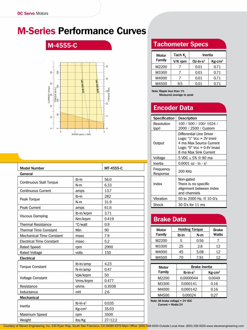
M-Series Performance CurvesM-4555-C
Model Number MT-4555-C
General
Continuous Stall Torquelb-in 56.0
N-m 6.33
Continuous Current amps 13.7
Peak Torquelb-in 282
N-m 31.9
Peak Current amps 61.6
Viscous Dampinglb-in/krpm 3.71
Nm/krpm 0.419
Thermal Resistance °C/watt 0.9
Thermal Time Constant Min 90
Mechanical Time Constant msec 7.9
Electrical Time Constant msec 5.2
Rated Speed rpm 2900
Rated Voltage volts 150
Electrical
Torque Constantlb-in/amp 4.23
N-m/amp 0.47
Voltage ConstantVpk/krpm 50
Vrms/krpm 0.477
Resistance ohms 0.3938
Inductance mH 2.6
Mechanical
Inertialb-in-s2 0.035
Kg-cm2 35.03
Maximum Speed rpm 3500
Weight lbs/Kg 27/12.2
CU
RR
EN
T (A
mps
)
TOR
QU
E (l
b-in
.)
3040
5020
10
M-4555-C
SPEED (rpm) x 1000
TOR
QU
E (N
m)
00
100
150
200
50
05
1015
2025
1 2 30
100 VDC
BU
S
150 VDC
BU
S
Tachometer Specs
MotorFamily
Tach KE Inertia
V/K rpm Oz-in-s2 Kg-cm2
M2200 7 0.01 0.71
M3300 7 0.01 0.71
M4000 7 0.01 0.71
M4500 9.5 0.01 0.71
Note: Ripple less than 1% Measured average to peak
Specification DescriptionResolution (ppr)
100 / 500 / 100/ 1024 / 2000 / 2500 / Custom
Output
Differential Line DriverLogic “1” Vcc = 2V (min) 4 ma Max Source CurrentLogic “0” Vcc = 0.4V (max) 8 ma Max Sink Current
Voltage 5 VDC ± 5% @ 80 ma
Inertia 0.0001 oz - in - s2
Frequency Response
200 KHz
IndexNon-gatedThere is no specific alignment between index and channels
Vibration 50 to 2000 Hz. @ 10 G's
Shock 30 G's for 11 ms
Encoder Data
Motor Family
Holding Torque Brake Wattslb-in N-m
M2200 5 0.56 7
M3300 25 2.8 12
M4000 45 5.08 12
M4500 70 7.91 12
Motor Family
Brake Inertia
lb-in-s2 Kg-cm2
M2200 0.0000044 0.0049
M3300 0.000141 0.16
M4000 0.000142 0.16
M4500 0.00024 0.27
Brake Data
Note: All brake voltage = 24 VDC Current = Watts/24
Courtesy of Steven Engineering, Inc.-230 Ryan Way, South San Francisco, CA 94080-6370-Main Office: (650) 588-9200-Outside Local Area: (800) 258-9200-www.stevenengineering.com
21
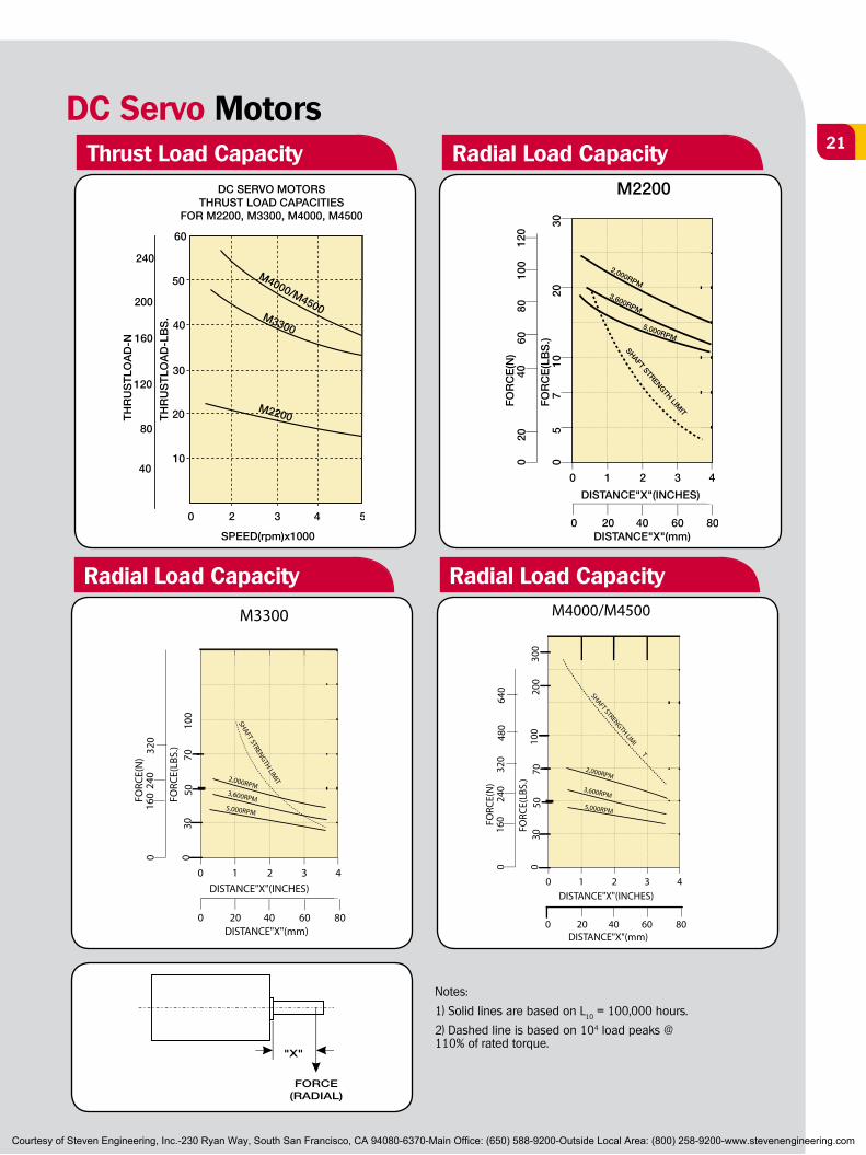
DC Servo MotorsThrust Load Capacity Radial Load Capacity
M2200
1
20 40 60 80
2 3 40
DISTANCE"X"(mm)
00F
OR
CE
(N)
FO
RC
E(L
BS
.)5
710
2030
2060
8010
0
5,000RPM
3,600RPM
2,000RPM
0
DISTANCE"X"(INCHES)
4012
0
SHAFT STRENGTH LIMIT
Radial Load Capacity Radial Load Capacity
M3300
1
20 40 60 80
2 3 40
DISTANCE"X"(mm)
30
0FO
RCE(
N)
FORC
E(LB
S.)
100
240
320
5,000RPM
3,600RPM
2,000RPM
0
DISTANCE"X"(INCHES)
160
7050
0
SHAFT STRENGTH LIMIT
M4000/M4500
1
20 40 60 80
2 3 40
DISTANCE"X"(mm)
30
0FO
RCE(
N)
FORC
E(LB
S.)
100
240
320
5,000RPM
3,600RPM
2,000RPM
0
DISTANCE"X"(INCHES)
160
7050
030
020
0
SHAFT STRENGTH LIMI
T
480
640
Notes:
1) Solid lines are based on L10 = 100,000 hours.
2) Dashed line is based on 104 load peaks @ 110% of rated torque.
FORCE(RADIAL)
"X"
Courtesy of Steven Engineering, Inc.-230 Ryan Way, South San Francisco, CA 94080-6370-Main Office: (650) 588-9200-Outside Local Area: (800) 258-9200-www.stevenengineering.com

DC Servo Motors
M2200 Series DimensionsDC Servo Motors
57<
<
Motor — TachometerStandard “C” Face Mounting
Optional “L” Mounting
Optional Terminations
Configuration LengthModel M MT MTE MTR ME MR MK MTKM2240 5.59/141.9 5.59/141.9 7.84/199.1 8.69/220.7 6.12/155.4 7.54/191.5 5.59/141.9 7.22/183.3
M2250 6.59/167.3 6.59/167.3 8.84/224.5 9.69/246.1 7.12/180.8 8.54/216.9 6.59/167.3 8.22/208.7
Note: Dimensions are in Inches/mm.
(4) M4 x 0.7 .31 DP90° apart on a 1.531 BC
Ø [38.887]/1.531
Optional “M" Mounting
Optional “D” Mounting
Option “A” Option “C”
Courtesy of Steven Engineering, Inc.-230 Ryan Way, South San Francisco, CA 94080-6370-Main Office: (650) 588-9200-Outside Local Area: (800) 258-9200-www.stevenengineering.com

23
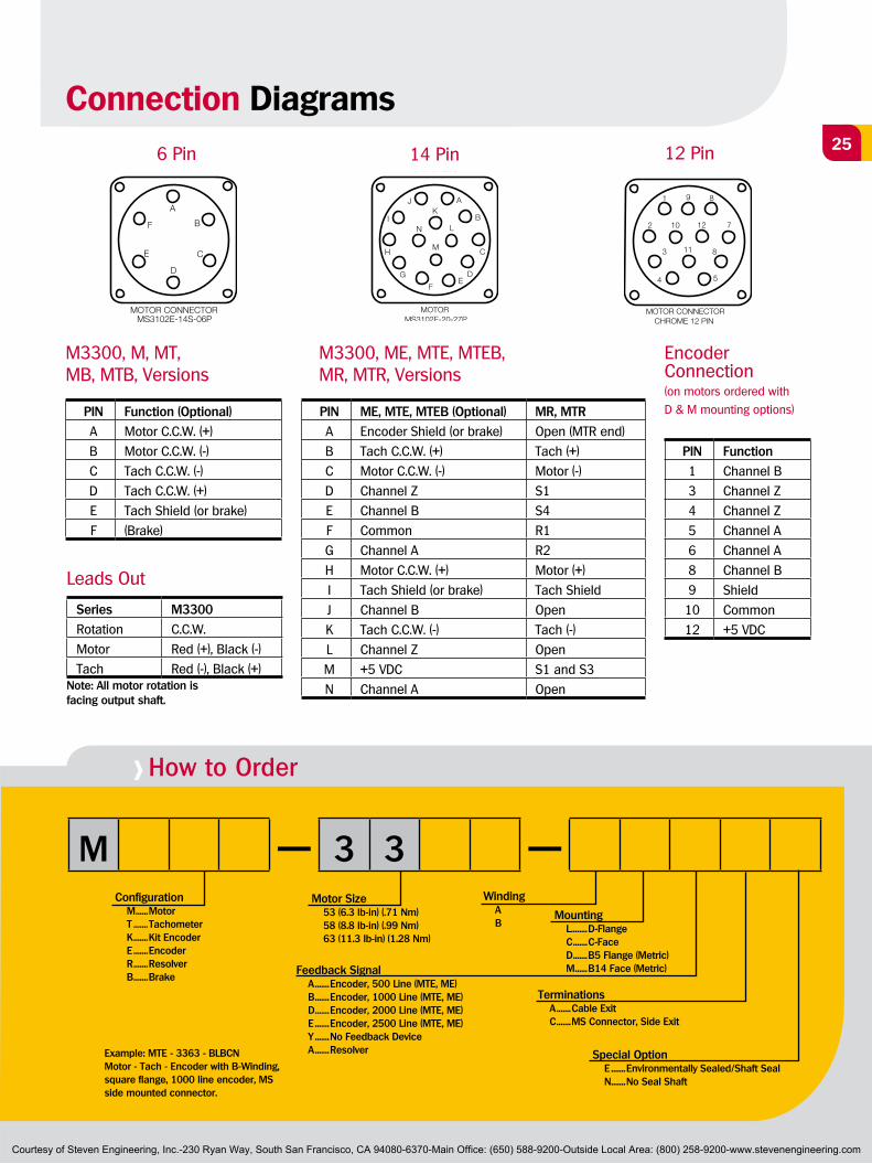
> How to Order
M — 2 2 — NConfiguration M ......Motor T .......Tachometer K .......Kit Encoder E .......Encoder R .......Resolver B .......Brake
Motor Size 40 (1.9 lb-in) (.21 Nm) 50 (3.1 lb-in) (.35 Nm)
Winding A B
Feedback Signal A .......Encoder, 500 Line (MTE, ME, MK) B .......Encoder, 1000 Line (MTE, ME, MK) D .......Encoder, 2000 Line (MTE, ME) E .......Encoder, 2500 Line (MTE, ME) Y .......No Feedback Device A .......Resolver (MTR, MR)
Mounting L........D-Flange C .......C-Face D .......B5 Flange (Metric) M ......B14 Face (Metric)
Terminations A .......Cable Exit C .......MS Connector, Side Exit R .......Rear Exit MS Conn.
Special Option N .......None
Example: MTE - 2250 - BLBCNMotor - Tach - Encoder with B-Winding, square flange, 1000 line encoder, MS side mounted connector.
Connection Diagrams14 Pin6 Pin
Series M2200
Rotation C.C.W.
Motor Red (+), Black (-)
Tach Red (-), Black (+)
Note: All motor rotation is facing output shaft.
Leads Out
PIN Function (Optional)
A Motor C.C.W. (+)
B Motor C.C.W. (-)
C Tach C.C.W. (-)
D Tach C.C.W. (+)
E Tach Shield (or brake)
F (Brake)
M2200, M, MT, MB, MTB, Versions
PIN Function (Optional)
A Encoder Shield (or brake)
B Tach C.C.W. (+)
C Motor C.C.W. (-)
D Channel Z
E Channel B
F Common
G Channel A
H Motor C.C.W. (+)
I Tach Shield (or brake)
J Channel B
K Tach C.C.W. (-)
L Channel Z
M +5 VDC
N Channel A
M2200, ME, MTE, MTEB, Versions
PIN Function (Optional)
A (Motor Ground)
B Tach Lead (+)
C Motor Lead (-)
D S1
E S4
F R1
G R2
H Motor Lead (+)
I Tach Shield
J Open
K Tach Lead (-)
L Open
M S1 and S3
N Open
M2200, MR,MTR, Versions
Courtesy of Steven Engineering, Inc.-230 Ryan Way, South San Francisco, CA 94080-6370-Main Office: (650) 588-9200-Outside Local Area: (800) 258-9200-www.stevenengineering.com
DC Servo MotorsNextMove Motion control solutions
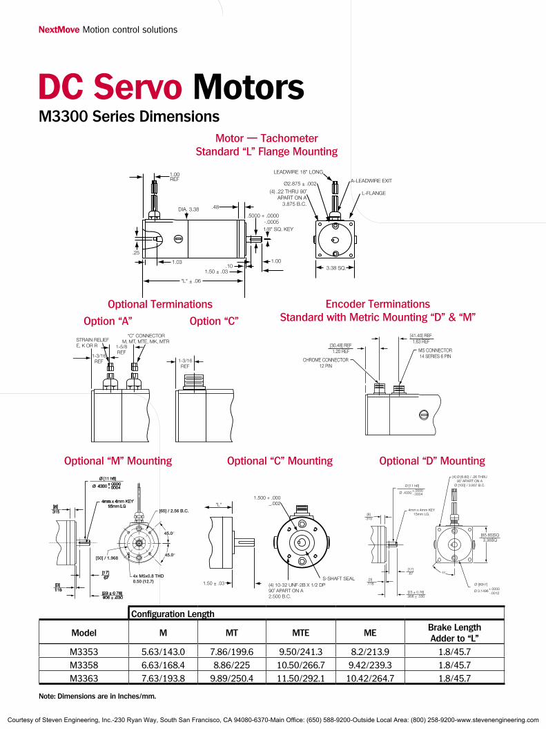
M3300 Series DimensionsDC Servo Motors
STRAIN RELIEFE, K OR R
“C” CONNECTORM, MT, MTE, MK, MTR
Motor — TachometerStandard “L” Flange Mounting
Optional “M” Mounting
Configuration Length
Model M MT MTE MEBrake LengthAdder to “L”
M3353 5.63/143.0 7.86/199.6 9.50/241.3 8.2/213.9 1.8/45.7M3358 6.63/168.4 8.86/225 10.50/266.7 9.42/239.3 1.8/45.7M3363 7.63/193.8 9.89/250.4 11.50/292.1 10.42/264.7 1.8/45.7
Note: Dimensions are in Inches/mm.
Optional “C" Mounting
Encoder TerminationsStandard with Metric Mounting “D" & “M”
Optional “D" Mounting
Optional Terminations
Option “A” Option “C”
Courtesy of Steven Engineering, Inc.-230 Ryan Way, South San Francisco, CA 94080-6370-Main Office: (650) 588-9200-Outside Local Area: (800) 258-9200-www.stevenengineering.com
25
> How to Order
M — 3 3 —Configuration M ......Motor T .......Tachometer K .......Kit Encoder E .......Encoder R .......Resolver B .......Brake
Motor Size 53 (6.3 lb-in) (.71 Nm) 58 (8.8 lb-in) (.99 Nm) 63 (11.3 lb-in) (1.28 Nm)
Winding A B
Feedback Signal A .......Encoder, 500 Line (MTE, ME) B .......Encoder, 1000 Line (MTE, ME) D .......Encoder, 2000 Line (MTE, ME) E .......Encoder, 2500 Line (MTE, ME) Y .......No Feedback Device A .......Resolver
Mounting L........D-Flange C .......C-Face D .......B5 Flange (Metric) M ......B14 Face (Metric)
Terminations A .......Cable Exit C .......MS Connector, Side Exit
Special Option E .......Environmentally Sealed/Shaft Seal N .......No Seal Shaft
Example: MTE - 3363 - BLBCNMotor - Tach - Encoder with B-Winding, square flange, 1000 line encoder, MS side mounted connector.
Connection Diagrams14 Pin6 Pin
Series M3300
Rotation C.C.W.
Motor Red (+), Black (-)
Tach Red (-), Black (+)Note: All motor rotation is facing output shaft.
Leads Out
PIN Function (Optional)
A Motor C.C.W. (+)
B Motor C.C.W. (-)
C Tach C.C.W. (-)
D Tach C.C.W. (+)
E Tach Shield (or brake)
F (Brake)
M3300, M, MT, MB, MTB, Versions
PIN ME, MTE, MTEB (Optional) MR, MTR
A Encoder Shield (or brake) Open (MTR end)
B Tach C.C.W. (+) Tach (+)
C Motor C.C.W. (-) Motor (-)
D Channel Z S1
E Channel B S4
F Common R1
G Channel A R2
H Motor C.C.W. (+) Motor (+)
I Tach Shield (or brake) Tach Shield
J Channel B Open
K Tach C.C.W. (-) Tach (-)
L Channel Z Open
M +5 VDC S1 and S3
N Channel A Open
M3300, ME, MTE, MTEB, MR, MTR, Versions
PIN Function
1 Channel B
3 Channel Z
4 Channel Z
5 Channel A
6 Channel A
8 Channel B
9 Shield
10 Common
12 +5 VDC
Encoder Connection(on motors ordered with
D & M mounting options)
12 Pin
Courtesy of Steven Engineering, Inc.-230 Ryan Way, South San Francisco, CA 94080-6370-Main Office: (650) 588-9200-Outside Local Area: (800) 258-9200-www.stevenengineering.com
DC Servo Motors
M4000 Series DimensionsDC Servo Motors
L ± .06
.100
2.50 ± .03
.6250+.0000- .0005
Ø2.186±.002
4.25 SQ.
(4) .266 thru 90°apart on a 4.950 B.C.
Motor — TachometerStandard “L” Flange Mounting
Optional “C” Mounting
Optional “N" Mounting
Configuration Length
Model M MT MTE MEBrake LengthAdder to “L”
M4050 7.27/184.7 7.04/178.8 9.2/233.6 9.2/233.6 2.46/62.4M4060 8.27/210.1 8.04/204.2 10.2/259 10.2/259 2.46/62.4M4070 9.27/235.5 9.04/229.6 11.2/284.4 11.2/284.4 2.46/62.4M4090 11.27/286.3 11.04/280.4 13.2/335.2 13.2/335.2 2.46/62.4
Note: Dimensions are in Inches/mm.
LEADWIRE EXIT
Optional Terminations
Optional “M" Mounting
Optional“D" Mounting
Encoder TerminationsStandard with Metric Mounting “D" & “M”Option “A” Option “B” Option “C”
Courtesy of Steven Engineering, Inc.-230 Ryan Way, South San Francisco, CA 94080-6370-Main Office: (650) 588-9200-Outside Local Area: (800) 258-9200-www.stevenengineering.com
27
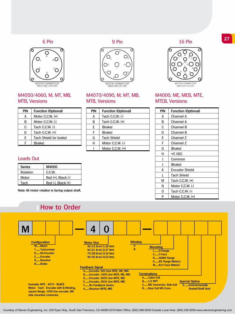
> How to Order
M — 4 0 —Configuration M ......Motor T .......Tachometer K .......Kit Encoder E .......Encoder R .......Resolver B .......Brake
Motor Size 50 (12 lb-in) (1.36 Nm) 60 (21 lb-in) (2.37 Nm) 70 (28 lb-in) (3.16 Nm) 90 (40 lb-in) (4.52 Nm)
Winding A B
Feedback Signal A .......Encoder, 500 Line (MTE, ME, MK) B .......Encoder, 1000 Line (MTE, ME, MK) D .......Encoder, 2000 Line (MTE, ME) E .......Encoder, 2500 Line (MTE, ME) Y .......No Feedback Device A .......Resolver (MTR, MR)
Mounting L........D-Flange C .......C-Face N .......NEMA Flange D .......B5 Flange (Metric) M ......B14 Face (Metric)
Terminations A .......Cable Exit B .......1/2 NPT C .......MS Connector, Side Exit R .......Rear Exit MS Conn.
Special Option E .......Environmentally Sealed/Shaft Seal
Example: MTE - 4070 - BLBCEMotor - Tach - Encoder with B-Winding, square flange, 1000 line encoder, MS side mounted connector.
9 Pin6 Pin
Series M4000
Rotation C.C.W.
Motor Red (+), Black (-)
Tach Red (-), Black (+)
Note: All motor rotation is facing output shaft.
Leads Out
PIN Function (Optional)
A Motor C.C.W. (+)
B Motor C.C.W. (-)
C Tach C.C.W. (-)
D Tach C.C.W. (+)
E Tach Shield (or brake)
F (Brake)
M4050/4060, M, MT, MB, MTB, Versions
PIN Function (Optional)
A Tach C.C.W. (-)
B Tach C.C.W. (+)
E (Brake)
F (Brake)
G Tach Shield
H Motor C.C.W. (-)
I Motor C.C.W. (+)
M4070/4090, M, MT, MB, MTB, Versions
PIN Function (Optional)
A Channel A
B Channel A
C Channel B
D Channel B
E Channel Z
F Channel Z
G (Brake)
H +5 VDC
I Common
J (Brake)
K Encoder Shield
L Tach Shield
M Tach C.C.W. (+)
N Motor C.C.W. (-)
O Tach C.C.W. (-)
P Motor C.C.W. (+)
M4000, ME, MEB, MTE, MTEB, Versions
16 Pin
Courtesy of Steven Engineering, Inc.-230 Ryan Way, South San Francisco, CA 94080-6370-Main Office: (650) 588-9200-Outside Local Area: (800) 258-9200-www.stevenengineering.com
DC Servo Motors
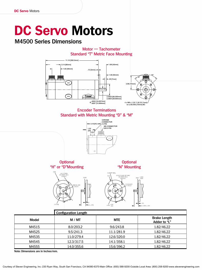
M4500 Series DimensionsDC Servo Motors
1.83 [46mm]
3.14 [80mm]
11.10 [282.0mm]
.12 [3mm]
1.69 [43mm]
1.36 [35mm]
.29 [7mm]
.6302 [16.007mm]
.6297 [15.994mm]Ø
2.3622 [60.000mm]2.3604 [59.954mm]
2.96 [75mm]
45°45°
4 x M8 x 1.25 .50 [12.7mm]on a Ø2.953 [75mm] BC
Motor — TachometerStandard “T” Metric Face Mounting
Configuration Length
Model M / MT MTEBrake LengthAdder to “L”
M4515 8.0/203.2 9.6/243.8 1.82/46.22M4525 9.5/241.3 11.1/281.9 1.82/46.22M4535 11.0/279.4 12.6/320.0 1.82/46.22M4545 12.3/317.5 14.1/358.1 1.82/46.22M4555 14.0/355.6 15.6/396.2 1.82/46.22
Note: Dimensions are in Inches/mm.
Optional “N" Mounting
Optional “H" or “D”Mounting
Encoder TerminationsStandard with Metric Mounting “D" & “M”
MS CONNECTOR20S 9 PIN
3.18 [81]
CHROMECONNECTOR 12 PIN
1.30[33]
Courtesy of Steven Engineering, Inc.-230 Ryan Way, South San Francisco, CA 94080-6370-Main Office: (650) 588-9200-Outside Local Area: (800) 258-9200-www.stevenengineering.com
29
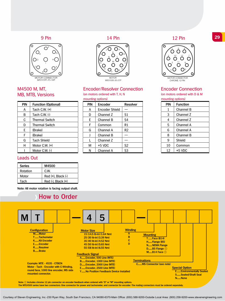
> How to Order
M T — 4 5 —Configuration M ......Motor T .......Tachometer K .......Kit Encoder E .......Encoder R .......Resolver B .......Brake
Motor Size 15 (14.5 lb-in) (1.64 Nm) 25 (30 lb-in) (3.39 Nm) 35 (40 lb-in) (4.52 Nm) 45 (50 lb-in) (5.65 Nm) 55 (58 lb-in) (6.55 Nm)
Winding A B C D
Feedback Signal A .......Encoder, 500 Line (MTE) B .......Encoder, 1000 Line (MTE) D .......Encoder, 2000 Line (MTE) E .......Encoder, 2500 Line (MTE) Y .......No Position Feedback Device Installed
Mounting T .......Face (B14) H .......Flange (B5) N .......NEMA Flange D .......B5 Flange 1 M ......B14 Face 1
Terminations C .......MS Connector (see note)
Special Option E .......Environmentally Sealed S .......Sealed/Shaft Seal N .......None
Example: MTE - 4535 - CTBCNMotor - Tach - Encoder with C-Winding, round face, 1000 line encoder, MS side mounted connector.
12 Pin9 Pin
Series M4500
Rotation C.W.
Motor Red (+), Black (-)
Tach Red (-), Black (+)
Note: All motor rotation is facing output shaft.
Leads Out
PIN Function (Optional)
A Tach C.W. (+)
B Tach C.W. (-)
C Thermal Switch
D Thermal Switch
E (Brake)
F (Brake)
G Tach Shield
H Motor C.W. (+)
I Motor C.W. (-)
M4500 M, MT, MB, MTB, Versions
PIN Encoder Resolver
A Encoder Shield —
D Channel Z S1
E Channel B S4
F Common R1
G Channel A R2
J Channel B —
L Channel Z —
M +5 VDC S2
N Channel A S3
Encoder Connection(on motors ordered with D & M
mounting options)
PIN Function
1 Channel B
3 Channel Z
4 Channel Z
5 Channel A
6 Channel A
8 Channel B
9 Shield
10 Common
12 +5 VDC
Encoder/Resolver Connection(on motors ordered with T, H, N
mounting options)
14 Pin
Note: 1 Includes chrome 12 pin connector on encoder feedback when ordered with “D” or “M” mounting options.The MTE4500 series have two connectors. One connector for power and tachometer, and connector for encoder. The mating connectors must be ordered separately.
Courtesy of Steven Engineering, Inc.-230 Ryan Way, South San Francisco, CA 94080-6370-Main Office: (650) 588-9200-Outside Local Area: (800) 258-9200-www.stevenengineering.com
DC Servo Motors
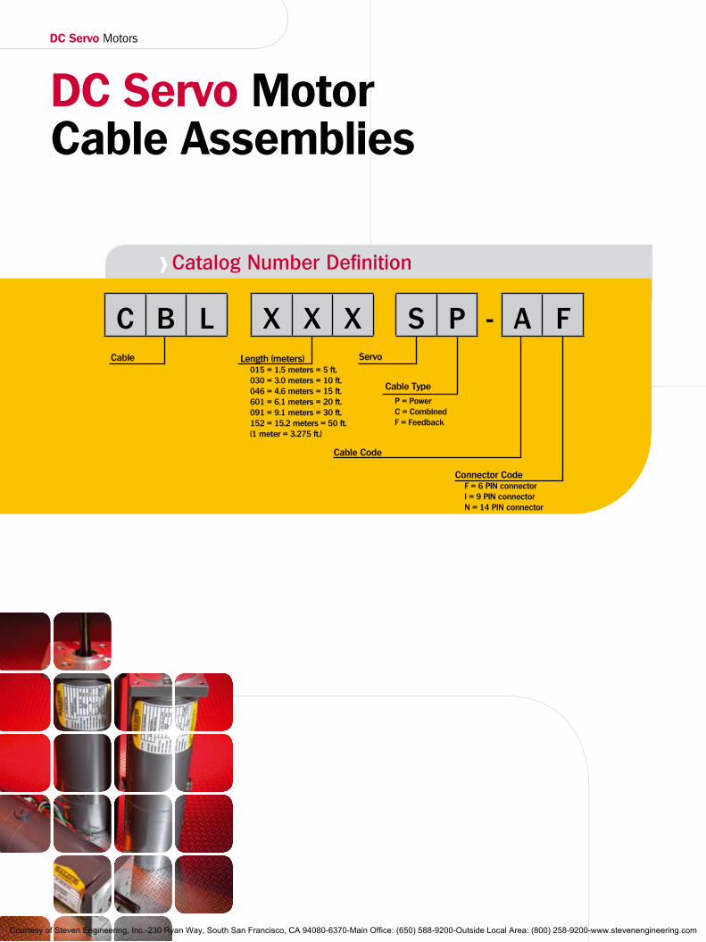
DC Servo Motor Cable Assemblies
> Catalog Number Definition
C B L X X X S P - A FCable Length (meters)
015 = 1.5 meters = 5 ft. 030 = 3.0 meters = 10 ft. 046 = 4.6 meters = 15 ft. 601 = 6.1 meters = 20 ft. 091 = 9.1 meters = 30 ft. 152 = 15.2 meters = 50 ft. (1 meter = 3.275 ft.)
Servo
Cable Type
P = Power C = Combined F = Feedback
Cable Code
Connector Code F = 6 PIN connector I = 9 PIN connector N = 14 PIN connector
Courtesy of Steven Engineering, Inc.-230 Ryan Way, South San Francisco, CA 94080-6370-Main Office: (650) 588-9200-Outside Local Area: (800) 258-9200-www.stevenengineering.com
31Motor PrefixNumber of
Connector PinsMating Connector
Order No.Cable assembly
Order No.Length
Meters Feet
M, MT - 2000M, MT, MTB, MB - 3000
6
MSCF
CBL030SP-AF 3.0 10
6 CBL061SP-AF 6.1 20
6 CBL091SP-AF 9.1 30
Cable Assembly used on M2200/3300 Motor Series
Cable End View
2-20 AWGPIN C PIN D
Drain Wire20 AWG
Drain Wire16 AWG
Drain Wire16 AWG
2-16 AWGPIN A PIN B
ShieldBinder
Shield
2-18 AWGPIN E PIN F
Shield1/4" Ref
3"Ref
Cable ConnectorMS 3106F-14S-06S
Length
0.44”/11.1mm Dia
M2200/3300 Cable Assembly
Cable End View
Drain Wire16 AWG
M2200/3300 Cable AssemblyDrain Wire16 AWG
Shield
Shield
ShieldShield
Shield
Shield
Shield
Drain Wire22 AWG
Drain Wire20 AWG
Shield
Binder
2-22 AWGPIN FPIN M
2-22 AWGPIN GPIN N
2-22 AWGPIN EPIN J
2-22 AWGPIN DPIN L
2-20 AWGPIN BPIN K
2-18 AWGPIN APIN I
2-14 AWGPIN CPIN H
Cable ConnectorMS 3106F-20-27S
1/4” Ref
3“ Ref
0.63”/16mm Dia
Length
6 Pin Function Pin
Motor CCW+ A
Motor CCW- B
Tach CCW- C
Tach CCW+ D
Tach Shield (or brake) E
Brake F
14 Pin Function Pin
Encoder Shield (or brake) A
Tach CCW+ B
Motor CCW- C
Channel Z D
Channel B E
Common F
Channel A G
Motor CCW+ H
Tach Shield (or brake) I
Channel B J
Tach CCW- K
Channel Z L
+5 VDC M
Channel A N
Motor PrefixNumber of
Connector PinsMating Connector
Order No.Cable assembly
Order No.Length
Meters Feet
MTE, ME - 2200MTE, ME, MTEB, MEB - 3300
14
MSCN
CBL030SC-GN 3.0 10
14 CBL061SC-GN 6.1 20
14 CBL091SC-GN 9.1 30
Courtesy of Steven Engineering, Inc.-230 Ryan Way, South San Francisco, CA 94080-6370-Main Office: (650) 588-9200-Outside Local Area: (800) 258-9200-www.stevenengineering.com
DC Servo Motors
Cable Assembly used on M4000/4500 Motor Series
Cable End View
2-20 AWGPIN A PIN B
Drain Wire20 AWGPIN G
Drain Wire14 AWG
Drain Wire16 AWG
ShieldBinder
Shield
2-18 AWGPIN E PIN F
Shield 1/4" Ref
3"Ref
Cable ConnectorMS 3106F-20-16S
2-18 AWGPIN C PIN D
2-14 AWGPIN H PIN I
0.63”/16mm Dia
Length
M4070/4090/4500 Cable Assembly
Cable End View
2-20 AWGPIN C PIN D
Drain Wire20 AWG
Drain Wire16 AWG
Drain Wire16 AWG
2-16 AWGPIN A PIN B
ShieldBinder
Shield
2-18 AWGPIN E PIN F
Shield1/4" Ref
3"Ref
Cable ConnectorMS 3106F-14S-06S
Length
0.44”/11.1mm Dia
M4050/4060 Cable Assembly
6 Pin M4050/4060
Function Pin
Motor CCW+ A
Motor CCW- B
Tach CCW- C
Tach CCW+ D
Tach Shield
(or brake)E
Brake F
9 Pin M4070/4090
Function Pin
Tach CCW- A
Tach CCW+ B
(Brake) E
(Brake) F
Tach Shield G
Motor CCW- H
Motor CCW+ I
M4500
Function Pin
Tach CCW- A
Tach CCW+ B
(Brake) E
(Brake) F
Tach Shield G
Motor CCW+ H
Motor CCW- I
Motor PrefixNumber of
Connector PinsMating Connector
Order No.Cable assembly
Order No.Length
Meters Feet
M, MT, MB, MTB - 4050/4060
6
MSCF
CBL030SP-AF 3.0 10
6 CBL061SP-AF 6.1 20
6 CBL091SP-AF 9.1 30
Motor PrefixNumber of
Connector PinsMating Connector
Order No.Cable assembly
Order No.Length
Meters Feet
M, MT, MTB, MB - 4070/4090M, MT, MTB, MB - 4500 1
9
MSCI
CBL030SP-BI 3.0 10
9 CBL061SP-BI 6.1 20
9 CBL091SP-BI 9.1 30Note: 1 The MTE-4500 Series with encoder feedback requires two cables; one for power and one for feedback.
Courtesy of Steven Engineering, Inc.-230 Ryan Way, South San Francisco, CA 94080-6370-Main Office: (650) 588-9200-Outside Local Area: (800) 258-9200-www.stevenengineering.com
33
Cable Assembly used on M4000/4500 Motor Series
CABLE END VIEW
2-26 AWGPIN J PIN E
2-26 AWGPIN L PIN D
Filler
2-26 AWGPIN NPIN G
ShieldBinder
Shield
22 AWGPIN M
1/4" Ref
3"Ref
Cable ConnectorMS 3106F-14S-06SBinder
22 AWGPIN F Length
0.44”/11.1mm Dia
M4500
Cable End View
2-14 AwgPIN N, PIN P
M4050/4070/4090 Cable Assembly
Drain Wire16 AwgShield
Shield
Shield
Shield
ShieldShield
Shield
Drain Wire16 Awg
Drain Wire22 Awg, PIN K
Drain Wire20 Awg, PIN L
Shield
2-18 AwgPIN G, PIN J
2-20 AwgPIN M, PIN O
2-22 AwgPIN E, PIN F
Binder2-22 AwgPIN A, PIN B
2-22 AwgPIN C, PIN D
2-22 AwgPIN H, PIN I
Cable
Length
1/4” Ref
3” Ref
0.63”/16mm Dia.
ConnectorMS 3106F-24-07S
16 Pin
Function Pin
Channel A A
Channel A/ B
Channel B C
Channel B/ D
Channel Z E
Channel Z/ F
(Brake) G
+5 VDC H
Common I
(Brake) J
Encoder Shield K
Tach Shield L
Tach CCW+ M
Motor CCW- N
Tach CCW- O
Motor CCW+ P
NOTE: 22 AWG are encoder signals, larger AWG are for mo-tor/tach/brake.
14 Pin Function Pin
Channel Z D
Channel B E
Common F
Channel A G
Channel B/ J
Channel Z/ L
+5 VDC M
Channel A/ N
Motor PrefixNumber of
Connector PinsMating Connector
Order No.Cable assembly
Order No.Length
Meters Feet
MTE, ME, MTEB, MEB -4050,-4060, -4070, -4090
16MSCP
CBL061SC-GP 6.1 20
16 CBL091SC-GP 9.1 30
Encoder Feedback forNumber of
Connector PinsMating Connector
Order No.Cable assembly
Order No.Length
Meters Feet
MTE, ME, MEB, MTEB - 45001
14
MSCN
CBL030SF-BN 3.0 10
14 CBL061SF-BN 6.1 20
14 CBL091SF-BN 9.1 30
Note: 1 The MTE-4500 Series with encoder feedback requires two cables; one for power and one for feedback.
Courtesy of Steven Engineering, Inc.-230 Ryan Way, South San Francisco, CA 94080-6370-Main Office: (650) 588-9200-Outside Local Area: (800) 258-9200-www.stevenengineering.com
DC Servo Motors
DC Servo ControlsIn 1952, Baldor began supplying the industry with reliable adjustable speed
controls. A benchmark was attained in 1983 when Baldor began shipping
servo controls - and since then, thousands and thousands of Baldor servo
controls have been shipped worldwide for many diverse applications.
Baldor products help increase productivity, improve quality, work hard - and
provide solutions for your application needs.
TSD SeriesTSD Series
MotionPositioning
YourPC
ProgrammingSoftware
MotorControl
Motor
HMIPanels
Baldor's TSD is a totally enclosed PWM drive for control of one or two DC servo motors. Panel mount
enclosure, completely stand-alone unit plugs into 115 or 220 Vac. Accepts industry standard ±10 VDC input command for operation in either velocity or current mode. Provides up to 5 amps continuous, 10 amps peak per axis. Fully protected unit. Easily interfaces to existing motion controllers.
LD SeriesLD SeriesThe LD series servo
control is an open chassis configuration similar to
the UM, however operates direct from 115 VAC. The LD
contains one or two servo control cards mounted onto a chassis, provide 15 amps continuous, 30 amps peak per axis. Protection for over/under voltage, over temperature, short circuit, etc.
Courtesy of Steven Engineering, Inc.-230 Ryan Way, South San Francisco, CA 94080-6370-Main Office: (650) 588-9200-Outside Local Area: (800) 258-9200-www.stevenengineering.com
35
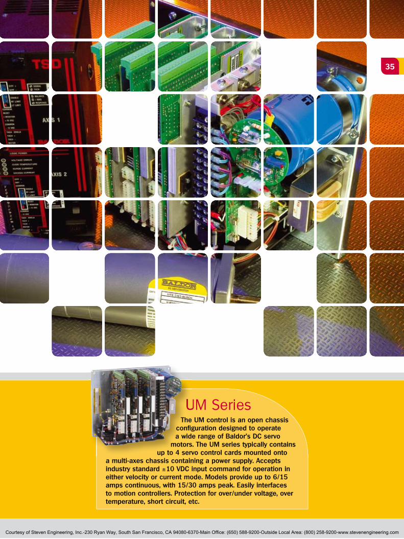
UM SeriesUM SeriesThe UM control is an open chassis
configuration designed to operate a wide range of Baldor's DC servo
motors. The UM series typically contains up to 4 servo control cards mounted onto
a multi-axes chassis containing a power supply. Accepts industry standard ±10 VDC input command for operation in either velocity or current mode. Models provide up to 6/15 amps continuous, with 15/30 amps peak. Easily interfaces to motion controllers. Protection for over/under voltage, over temperature, short circuit, etc.
Courtesy of Steven Engineering, Inc.-230 Ryan Way, South San Francisco, CA 94080-6370-Main Office: (650) 588-9200-Outside Local Area: (800) 258-9200-www.stevenengineering.com
DC Servo Motors
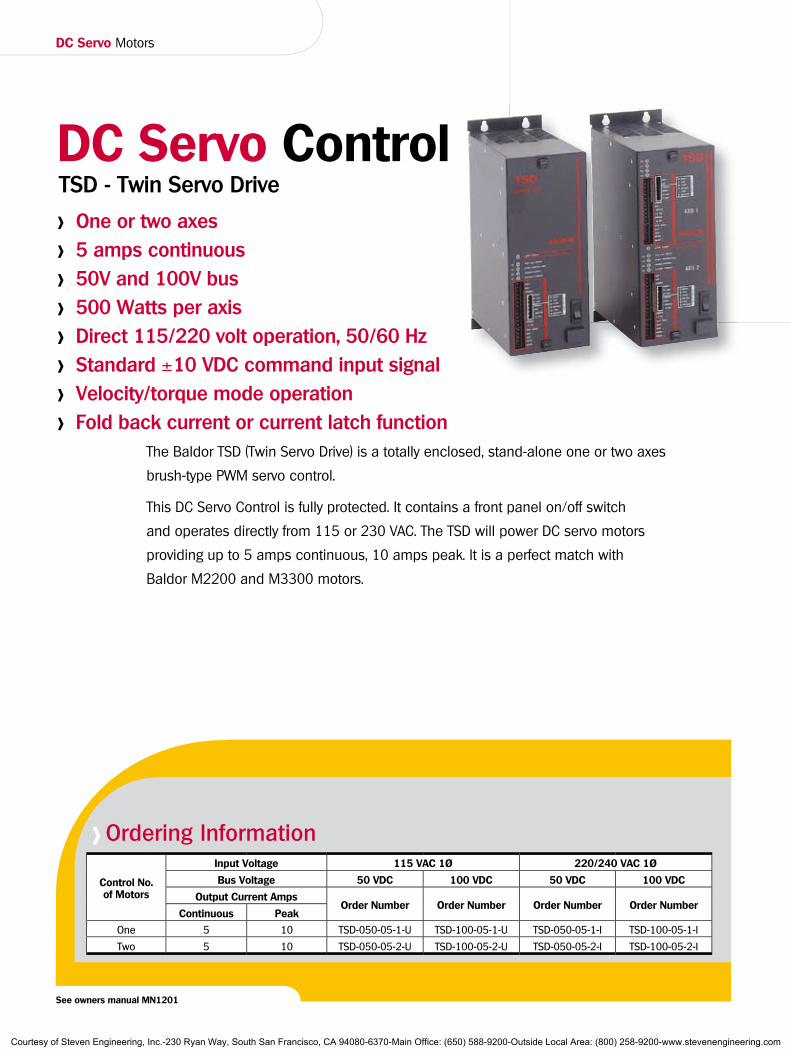
The Baldor TSD (Twin Servo Drive) is a totally enclosed, stand-alone one or two axes
brush-type PWM servo control.
This DC Servo Control is fully protected. It contains a front panel on/off switch
and operates directly from 115 or 230 VAC. The TSD will power DC servo motors
providing up to 5 amps continuous, 10 amps peak. It is a perfect match with
Baldor M2200 and M3300 motors.
> One or two axes
> 5 amps continuous
> 50V and 100V bus
> 500 Watts per axis
> Direct 115/220 volt operation, 50/60 Hz
> Standard ±10 VDC command input signal
> Velocity/torque mode operation
> Fold back current or current latch function
TSD - Twin Servo DriveDC Servo Control
See owners manual MN1201
> Ordering Information
Control No. of Motors
Input Voltage 115 VAC 1Ø 220/240 VAC 1Ø
Bus Voltage 50 VDC 100 VDC 50 VDC 100 VDC
Output Current AmpsOrder Number Order Number Order Number Order Number
Continuous Peak
One 5 10 TSD-050-05-1-U TSD-100-05-1-U TSD-050-05-1-I TSD-100-05-1-I
Two 5 10 TSD-050-05-2-U TSD-100-05-2-U TSD-050-05-2-I TSD-100-05-2-I
Courtesy of Steven Engineering, Inc.-230 Ryan Way, South San Francisco, CA 94080-6370-Main Office: (650) 588-9200-Outside Local Area: (800) 258-9200-www.stevenengineering.com
37
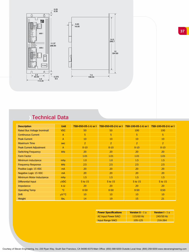
> Technical DataDescription Unit TSD-050-05-1-U or I TSD-050-05-2-U or I TSD-100-05-1-U or I TSD-100-05-2-U or I
Rated Bus Voltage (nominal) VDC 50 50 100 100
Continuous Current A 5 5 5 5
Peak Current A 10 10 10 10
Maximum Time sec 2 2 2 2
Peak Current Adjustment A 0-10 0-10 0-10 0-10
Switching Frequency kHz 20 20 20 20
Form Factor 1.01 1.01 1.01 1.01
Minimum inductance mhy 1.0 1.0 1.5 1.5
Frequency Response kHz 2.5 2.5 2.5 2.5
Positive Logic 15 VDC mA 20 20 20 20
Negative Logic 15 VDC mA 20 20 20 20
Minimum Motor Inductance mhy 1.5 1.5 1.5 1.5
Differential Input ±VDC 5 to 15 5 to 15 5 to 15 5 to 15
Impedance k Ω 20 20 20 20
Operating Temp °C 0-50 0-50 0-50 0.50
Drift µV/°C 10 10 10 10
Weight lbs. 14 19 15 21
Power Specifications Version U - 1 φ Version I - 1 φAC Input Power (VAC) 115/60 Hz 240/50 Hz
Input Range (VAC) 105-125 216-264
0.256.35
0.3759.5
11.37288.90
2.563.50
4.5114.30
0.6316.00
12304.80
7.5190.50
10.5266.7
Courtesy of Steven Engineering, Inc.-230 Ryan Way, South San Francisco, CA 94080-6370-Main Office: (650) 588-9200-Outside Local Area: (800) 258-9200-www.stevenengineering.com
DC Servo Motors
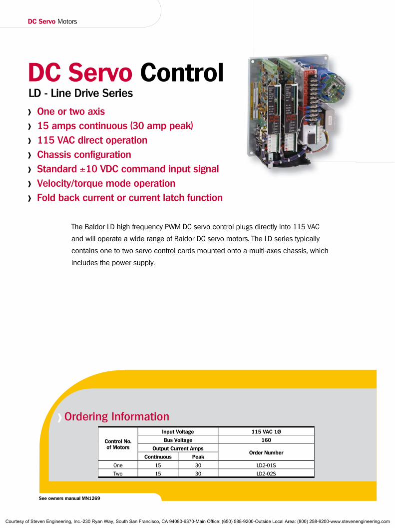
The Baldor LD high frequency PWM DC servo control plugs directly into 115 VAC
and will operate a wide range of Baldor DC servo motors. The LD series typically
contains one to two servo control cards mounted onto a multi-axes chassis, which
includes the power supply.
> One or two axis
> 15 amps continuous (30 amp peak)
> 115 VAC direct operation
> Chassis configuration
> Standard ±10 VDC command input signal
> Velocity/torque mode operation
> Fold back current or current latch function
LD - Line Drive SeriesDC Servo Control
> Ordering Information
Control No. of Motors
Input Voltage 115 VAC 1Ø
Bus Voltage 160
Output Current AmpsOrder Number
Continuous Peak
One 15 30 LD2-01S
Two 15 30 LD2-02S
See owners manual MN1269
Courtesy of Steven Engineering, Inc.-230 Ryan Way, South San Francisco, CA 94080-6370-Main Office: (650) 588-9200-Outside Local Area: (800) 258-9200-www.stevenengineering.com
39
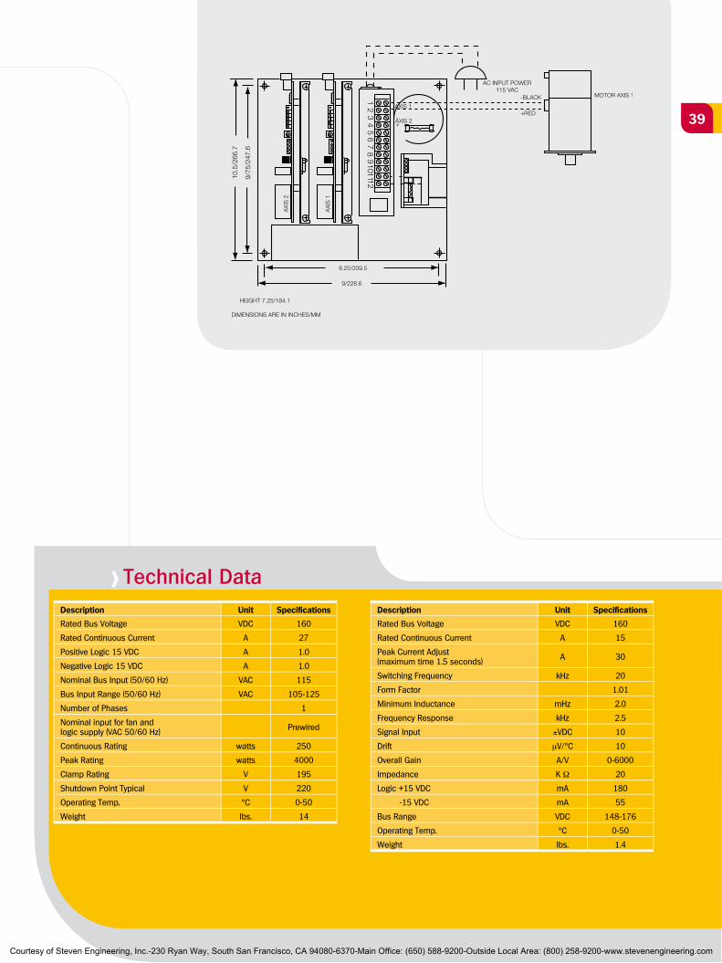
> Technical DataDescription Unit Specifications
Rated Bus Voltage VDC 160
Rated Continuous Current A 27
Positive Logic 15 VDC A 1.0
Negative Logic 15 VDC A 1.0
Nominal Bus Input (50/60 Hz) VAC 115
Bus Input Range (50/60 Hz) VAC 105-125
Number of Phases 1
Nominal input for fan and logic supply (VAC 50/60 Hz) Prewired
Continuous Rating watts 250
Peak Rating watts 4000
Clamp Rating V 195
Shutdown Point Typical V 220
Operating Temp. °C 0-50
Weight lbs. 14
Description Unit Specifications
Rated Bus Voltage VDC 160
Rated Continuous Current A 15
Peak Current Adjust (maximum time 1.5 seconds) A 30
Switching Frequency kHz 20
Form Factor 1.01
Minimum Inductance mHz 2.0
Frequency Response kHz 2.5
Signal Input ±VDC 10
Drift µV/°C 10
Overall Gain A/V 0-6000
Impedance K Ω 20
Logic +15 VDC mA 180
-15 VDC mA 55
Bus Range VDC 148-176
Operating Temp. °C 0-50
Weight lbs. 1.4
Courtesy of Steven Engineering, Inc.-230 Ryan Way, South San Francisco, CA 94080-6370-Main Office: (650) 588-9200-Outside Local Area: (800) 258-9200-www.stevenengineering.com
DC Servo Motors
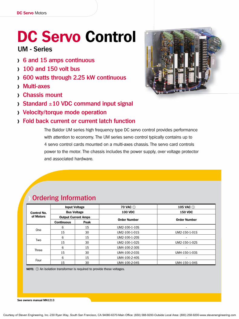
> Ordering Information
Control No. of Motors
Input Voltage 70 VAC 1 105 VAC 1
Bus Voltage 100 VDC 150 VDC
Output Current AmpsOrder Number Order Number
Continuous Peak
One6 15 UM2-100-1-10S -
15 30 UM2-100-1-01S UM2-150-1-01S
Two6 15 UM2-100-1-20S -
15 30 UM2-100-1-02S UM2-150-1-02S
Three6 15 UM4-100-2-30S -
15 30 UM4-100-2-03S UM4-150-1-03S
Four6 15 UM4-100-2-40S -
15 30 UM4-100-2-04S UM4-150-1-04S
NOTE: 1 An isolation transformer is required to provide these voltages.
See owners manual MN1213
The Baldor UM series high frequency type DC servo control provides performance
with attention to economy. The UM series servo control typically contains up to
4 servo control cards mounted on a multi-axes chassis. The servo card controls
power to the motor. The chassis includes the power supply, over voltage protector
and associated hardware.
> 6 and 15 amps continuous
> 100 and 150 volt bus
> 600 watts through 2.25 kW continuous
> Multi-axes
> Chassis mount
> Standard ±10 VDC command input signal
> Velocity/torque mode operation
> Fold back current or current latch function
UM - SeriesDC Servo Control
Courtesy of Steven Engineering, Inc.-230 Ryan Way, South San Francisco, CA 94080-6370-Main Office: (650) 588-9200-Outside Local Area: (800) 258-9200-www.stevenengineering.com
41
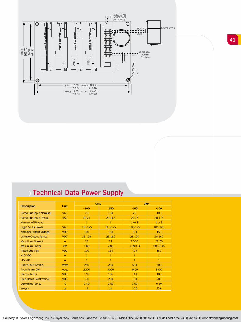
> Technical Data Power Supply
Description UnitUM2 UM4
-100 -150 -100 -150
Rated Bus Input Nominal VAC 70 150 70 105
Rated Bus Input Range VAC 20-77 20-115 20-77 20-115
Number of Phases 1 1 1 or 3 1 or 3
Logic & Fan Power VAC 105-125 105-125 105-125 105-125
Nominal Output Voltage VDC 100 150 100 150
Voltage Output Range VDC 28-109 28-162 28-109 28-162
Max. Cont. Current A 27 27 27/50 27/50
Maximum Power kW 1.89 2.86 1.89/4.3 2.86/6.45
Rated Bus Volt. VDC 100 150 100 150
+15 VDC A 1 1 1 1
-15 VDC A 1 1 1 1
Continuous Rating watts 250 250 500 500
Peak Rating (W) watts 2200 4000 4400 8000
Clamp Rating VDC 118 185 118 185
Shut Down Point typical VDC 130 200 130 200
Operating Temp. °C 0-50 0-50 0-50 0-50
Weight lbs. 14 14 20.6 20.6
Height = 7.25 (184.15)
Courtesy of Steven Engineering, Inc.-230 Ryan Way, South San Francisco, CA 94080-6370-Main Office: (650) 588-9200-Outside Local Area: (800) 258-9200-www.stevenengineering.com
DC Servo Motors
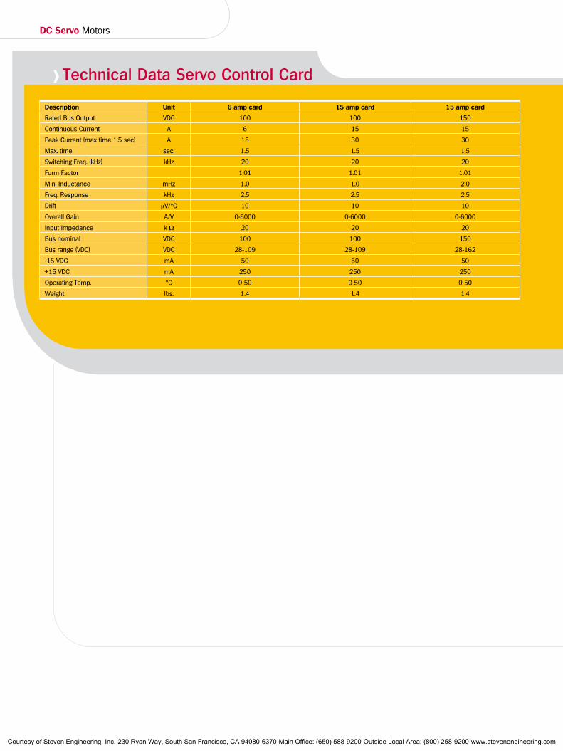
> Technical Data Servo Control Card
Description Unit 6 amp card 15 amp card 15 amp card
Rated Bus Output VDC 100 100 150
Continuous Current A 6 15 15
Peak Current (max time 1.5 sec) A 15 30 30
Max. time sec. 1.5 1.5 1.5
Switching Freq. (kHz) kHz 20 20 20
Form Factor 1.01 1.01 1.01
Min. Inductance mHz 1.0 1.0 2.0
Freq. Response kHz 2.5 2.5 2.5
Drift µV/°C 10 10 10
Overall Gain A/V 0-6000 0-6000 0-6000
Input Impedance k Ω 20 20 20
Bus nominal VDC 100 100 150
Bus range (VDC) VDC 28-109 28-109 28-162
-15 VDC mA 50 50 50
+15 VDC mA 250 250 250
Operating Temp. °C 0-50 0-50 0-50
Weight lbs. 1.4 1.4 1.4
Courtesy of Steven Engineering, Inc.-230 Ryan Way, South San Francisco, CA 94080-6370-Main Office: (650) 588-9200-Outside Local Area: (800) 258-9200-www.stevenengineering.com
43
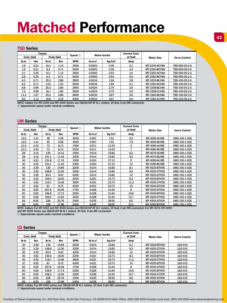
Matched Performance
TorqueSpeed 1 Motor Inertia
Current Cont. at Stall Motor Size Servo ControlCont. Stall Peak Stall
lb-in Nm lb-in Nm RPM lb-in-s2 Kg-Cm2 Amp
1.9 0.21 10.1 1.14 3500 0.0003 0.35 2.1 MT-2240-ACYAN TSD-050-05-2-U1.9 0.21 6.3 0.71 5000 0.0003 0.35 3.4 MT-2240-BCYAN TSD-050-05-2-U3.1 0.35 10.1 1.14 3500 0.0005 0.54 3.4 MT-2250-ACYAN TSD-050-05-2-U2.8 0.35 6.3 0.71 5000 0.0005 0.54 5.0 MT-2250-BCYAN TSD-050-05-2-U6.3 0.71 25.3 2.86 2800 0.0016 1.84 2.8 MT-3353-BLYAN TSD-100-05-2-U6.3 0.71 13.5 1.53 5000 0.0016 1.84 5.1 MT-3353-DLYAN TSD-100-05-2-U8.8 0.99 25.3 2.86 2800 0.0024 2.75 3.8 MT-3358-BLYAN TSD-100-05-2-U7.3 0.99 16.1 1.82 5000 0.0024 2.75 5.0 MT-3358-CLYAN TSD-100-05-2-U
11.3 1.27 25.3 2.86 2800 0.0033 3.67 4.9 MT-3363-BLYAN TSD-100-05-2-U9.0 1.12 19.8 2.24 4200 0.0033 3.67 5.0 MT-3363-CLYAN TSD-100-05-2-U
NOTE: Cables: For MT-2200 and MT-3300 Series use CBL061SP-AF (6.1 meters, 20 feet, 6 pin MS connector). 1 Approximate speed under nominal conditions.
TorqueSpeed 1 Motor Inertia
Current Cont. at Stall Motor Size Servo ControlCont. Stall Peak Stall
lb-in Nm lb-in Nm RPM lb-in-s2 Kg-Cm2 Amp
12.5 1.41 38 4.29 3000 0.007 7.91 5.5 MT-4050-ALYBE UM2-100-1-20S12.5 1.41 45 5.08 4500 0.007 7.91 7.9 MT-4050-BLYBE UM2-100-1-02S21.5 2.43 72 8.13 1500 0.011 12.43 5 MT-4060-ALYBE UM2-100-1-20S21.5 2.43 72 8.13 2300 0.011 12.43 7 MT-4060-BLYBE UM2-100-1-02S28 3.16 125 14.12 1500 0.014 15.82 6.2 MT-4070-ALYBE UM2-100-1-02S28 3.16 101.1 11.42 2300 0.014 15.82 9.2 MT-4070-BLYBE UM2-100-1-02S40 4.52 151.8 17.15 1500 0.024 27.12 9 MT-4090-ALYBE UM2-100-1-02S40 4.52 101.1 11.42 2300 0.024 27.12 13 MT-4090-BLYBE UM2-100-1-02S30 3.39 130 14.69 2200 0.014 15.82 6.1 MT-4525-BTYCN UM2-150-1-02S30 3.39 108.9 12.30 3200 0.014 15.82 9.2 MT-4525-CTYCN UM2-150-1-02S30 3.39 83.4 9.42 4200 0.014 15.82 12 MT-4525-DTYCN UM2-150-1-02S40 4.52 159.3 18.00 2200 0.021 23.73 8.3 MT-4535-BTYCN UM2-150-1-02S40 4.52 119.1 13.46 3000 0.021 23.73 11.2 MT-4535-CTYCN UM2-150-1-02S37 4.52 81 9.15 4200 0.021 23.73 15 MT-4535-DTYCN UM2-150-1-02S50 5.65 207.6 23.46 1700 0.028 31.64 8 MT-4545-ATYCN UM2-150-1-02S50 5.65 156.9 17.73 2200 0.028 31.64 10.6 MT-4545-BTYCN UM2-150-1-02S50 5.65 106.2 12.00 3200 0.028 31.64 15.7 MT-4545-CTYCN UM2-150-1-02S56 6.55 228 25.76 1500 0.035 39.55 8.5 MT-4555-ATYCN UM2-150-1-02S56 6.55 159 17.96 2400 0.035 39.55 12.1 MT-4555-BTYCN UM2-150-1-02S
NOTE: Cables: For MT-4050 and MT-4060 Series use CBL061SP-AF (6.1 meters, 20 feet, 6 pin MS connector). For MT-4070, MT-4090 and MT-4500 Series use CBL061SP-BI (6.1 meters, 20 feet, 9 pin MS connector).1 Approximate speed under nominal conditions.
TorqueSpeed 1º Motor Inertia
Current Cont. at Stall Motor Size Servo ControlCont. Stall Peak Stall
lb-in Nm lb-in Nm RPM lb-in-s2 Kg-Cm2 Amp
30 3.39 130 14.69 2200 0.014 15.82 6.1 MT-4525-BTYCN LD2-01S30 3.39 108.9 12.30 3200 0.014 15.82 9.2 MT-4525-CTYCN LD2-01S30 3.39 83.4 9.42 4200 0.014 15.82 12 MT-4525-DTYCN LD2-01S40 4.52 159.3 18.00 2200 0.021 23.73 8.3 MT-4535-BTYCN LD2-01S40 4.52 119.1 13.46 3000 0.021 23.73 11.2 MT-4535-CTYCN LD2-01S37 4.52 81 9.15 4200 0.021 23.73 15 MT-4535-DTYCN LD2-01S50 5.65 207.6 23.46 1700 0.028 31.64 8 MT-4545-ATYCN LD2-01S50 5.65 156.9 17.73 2200 0.028 31.64 10.6 MT-4545-BTYCN LD2-01S50 5.65 106.2 12.00 3200 0.028 31.64 15.7 MT-4545-CTYCN LD2-01S56 6.55 228 25.76 1500 0.035 39.55 8.5 MT-4555-ATYCN LD2-01S56 6.55 159 17.96 2400 0.035 39.55 12.1 MT-4555-BTYCN LD2-01S
NOTE: Cables: For MT-4500 series use CBL061SP-BI (6.1 meters, 20 feet, 9 pin MS connector). 1 Approximate speed under nominal conditions.
TSD Series
UM Series
LD Series
Courtesy of Steven Engineering, Inc.-230 Ryan Way, South San Francisco, CA 94080-6370-Main Office: (650) 588-9200-Outside Local Area: (800) 258-9200-www.stevenengineering.com

DC Servo Motors
Conversion Tables
Rotary Inertia (To convert from A to B, multiply by value in table)
B gm-cm2 oz-in2 gm-cm-s2 kg-cm2 lb-in2 oz-in-s2 lb-ft2 kg-cm-s2 lb-in-s2 lb-ft-s2 or
slug-ft2 Agm-cm2 1 5.46 x 10³ 1.01 x 10³ 103 3.417 x 10⁴ 1.41 x 10⁵ 2.37 x 10⁶ 1.01 x 10⁶ 8.85 x 10⁷ 7.37 x 10⁸
oz-in2 182.9 1 0.186 0.182 0.0625 2.59 x 10³ 4.34 x 10⁴ 1.86 x 10⁴ 1.61 x 10⁴ 1.34 x 10⁵
gm-cm-s2 980.6 5.36 1 0.9806 0.335 1.38 x 10² 2.32 x 10³ 103 8.67 x 10⁴ 7.23 x 10⁵
kg-cm2 1000 5.46 1.019 1 0.3417 1.41 x 10² 2.37 x 10³ 1.019 x 10³ 8.85 x 10⁴ 7.37 x 10⁵
lb-in2 2.92 x 10³ 16 2.984 2.926 1 4.14 x 10² 6.94 x 10³ 2.98 x 10³ 2.59 x 10³ 2.15 x 10⁴
oz-in-s2 7.06 x 101 386.08 72 700.615 24.13 1 0.1675 7.20 x 10² 6.25 x 10² 5.20 x 10³
lb-in-s2 4.21 x 10² 2304 429.71 421.40 144 5.967 1 0.4297 0.3729 3.10 x 10²
kg-cm-s2 9.8 x 10⁵ 5.36 x 10³ 1000 980.66 335.1 13.887 2.327 1 0.8679 7.23 x 10²
lb-ft-s2 1.129 x 10⁶ 6.177 x 10³ 1.152 x 10³ 1.129 x 10³ 386.08 16 2.681 1.152 1 8.33 x 10²
lb-ft-s2
or slug-ft2 1.355 x 10⁷ 7.41 x 10⁴ 1.38 x 10⁴ 1.35 x 10⁴ 4.63 x 10³ 192 32.17 13.825 12 1
Torque (To convert from A to B, multiply by value in table)
B dyne-cm gm-cm oz-in kg-cm lb-in Newton-m lb-ft kg-cm
Adyne-cm 1 1.019 x 10³ 1.416 x 10⁵ 1.0197 x 10⁶ 8.850 x 10⁷ 107 7.375 x 10⁸ 1.019 x 10⁸
gm-cm 980.65 1 1.388 x 10² 103 8.679 x 10⁴ 9.806 x 10⁵ 7.233 x 10⁵ 105oz-in 7.061 x 10⁴ 72.007 1 7.200 x 10² 6.25 x 10² 7.061 x 10³ 5.208 x 10³ 7.200 x 10⁴
kg-cm 9.806 x 10⁵ 1000 13.877 1 0.8679 9.806 x 10² 7.233 x 10² 102lb-in 1.129 x 10⁶ 1.152 x 10³ 16 1.152 1 0.112 8.333 x 10² 1.152 x 10²
Newton-m 107 1.019 x 10⁴ 141.612 10.197 8.850 1 0.737 0.101lb-ft 1.355 x 10⁷ 1.382 x 10⁴ 192 13.825 12 1.355 1 0.138kg-m 9.806 x 10⁷ 105 1.388 x 10³ 100 86.796 9.806 7.233 1
Material DensitiesOz/in2 lb/in3 gm/cm3
Aluminum 1.57 0.098 2.72
Brass 4.96 0.31 8.6
Bronze 4.72 0.295 8.17
Copper 5.15 0.322 8.91
Plastic 0.64 0.04 1.11
Steel 4.48 0.28 7.75
Mechanism EfficienciesAcme Screw (Bronze Nut) 0.4
Acme Screw (Plastic Nut) 0.5
Ball Screw 0.9
Helical Gear 0.7
Spur Gear 0.6
Timing Belt/Pulley 0.9
Friction Coefficients(Sliding) m
Steel on Steel 0.58
Steel on Steel (Greased) 0.15
Aluminum on Steel 0.45
Copper on Steel 0.36
Brass on Steel 0.40
Plastic on Steel 0.20
Linear Bearings 0.001
Temperature°F = (1.8 x °C) + 32
°C = .555 (°F - 32)
Gravity(Acceleration Constant)
g = 386 in/s2 = 32.2 ft/s2 = 9.8 m/s2
Courtesy of Steven Engineering, Inc.-230 Ryan Way, South San Francisco, CA 94080-6370-Main Office: (650) 588-9200-Outside Local Area: (800) 258-9200-www.stevenengineering.com
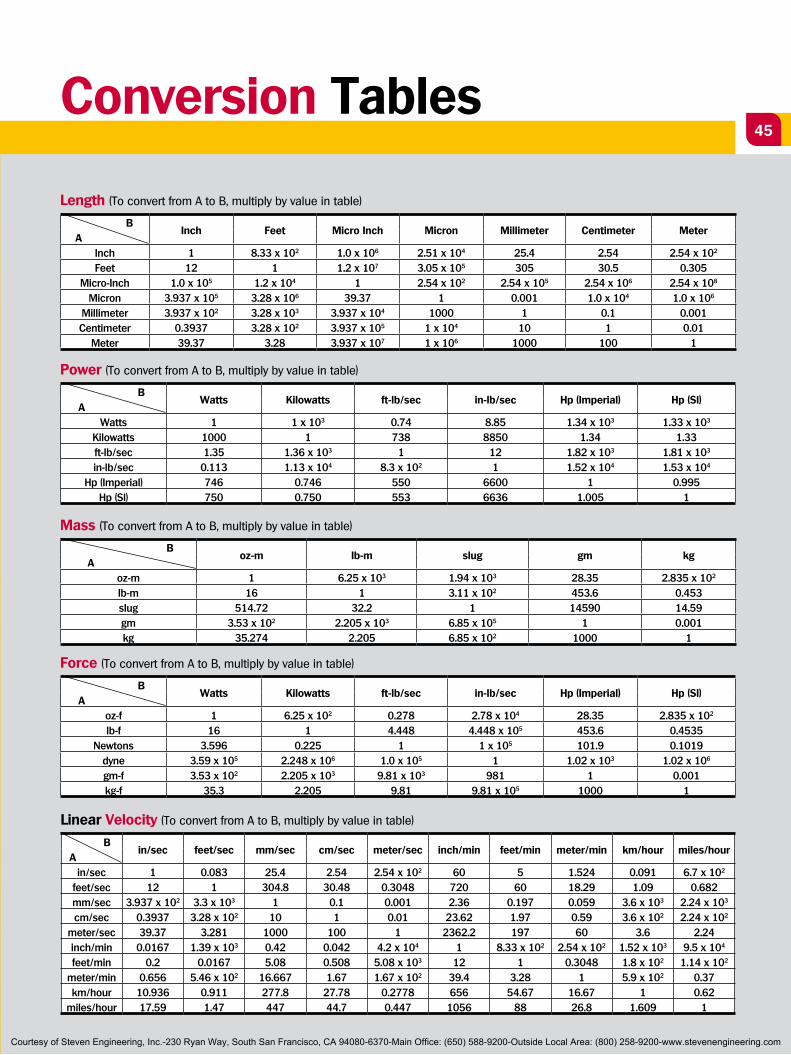
45Conversion Tables
Length (To convert from A to B, multiply by value in table)
B Inch Feet Micro Inch Micron Millimeter Centimeter Meter
AInch 1 8.33 x 10² 1.0 x 10⁶ 2.51 x 10⁴ 25.4 2.54 2.54 x 10²
Feet 12 1 1.2 x 10⁷ 3.05 x 10⁵ 305 30.5 0.305Micro-Inch 1.0 x 10⁵ 1.2 x 10⁴ 1 2.54 x 10² 2.54 x 10⁵ 2.54 x 10⁶ 2.54 x 10⁸
Micron 3.937 x 10⁵ 3.28 x 10⁶ 39.37 1 0.001 1.0 x 10⁴ 1.0 x 10⁶
Millimeter 3.937 x 10² 3.28 x 10³ 3.937 x 10⁴ 1000 1 0.1 0.001Centimeter 0.3937 3.28 x 10² 3.937 x 10⁵ 1 x 10⁴ 10 1 0.01
Meter 39.37 3.28 3.937 x 10⁷ 1 x 10⁶ 1000 100 1
Power (To convert from A to B, multiply by value in table)
B Watts Kilowatts ft-lb/sec in-lb/sec Hp (Imperial) Hp (Sl)
AWatts 1 1 x 10³ 0.74 8.85 1.34 x 10³ 1.33 x 10³
Kilowatts 1000 1 738 8850 1.34 1.33ft-lb/sec 1.35 1.36 x 10³ 1 12 1.82 x 10³ 1.81 x 10³
in-lb/sec 0.113 1.13 x 10⁴ 8.3 x 10² 1 1.52 x 10⁴ 1.53 x 10⁴
Hp (Imperial) 746 0.746 550 6600 1 0.995Hp (Sl) 750 0.750 553 6636 1.005 1
Mass (To convert from A to B, multiply by value in table)
B oz-m lb-m slug gm kg
Aoz-m 1 6.25 x 10³ 1.94 x 10³ 28.35 2.835 x 10²
lb-m 16 1 3.11 x 10² 453.6 0.453slug 514.72 32.2 1 14590 14.59gm 3.53 x 10² 2.205 x 10³ 6.85 x 10⁵ 1 0.001kg 35.274 2.205 6.85 x 10² 1000 1
Force (To convert from A to B, multiply by value in table)
B Watts Kilowatts ft-lb/sec in-lb/sec Hp (Imperial) Hp (Sl)
Aoz-f 1 6.25 x 10² 0.278 2.78 x 10⁴ 28.35 2.835 x 10²
lb-f 16 1 4.448 4.448 x 10⁵ 453.6 0.4535Newtons 3.596 0.225 1 1 x 10⁵ 101.9 0.1019
dyne 3.59 x 10⁵ 2.248 x 10⁶ 1.0 x 10⁵ 1 1.02 x 10³ 1.02 x 10⁶
gm-f 3.53 x 10² 2.205 x 10³ 9.81 x 10³ 981 1 0.001kg-f 35.3 2.205 9.81 9.81 x 10⁵ 1000 1
Linear Velocity (To convert from A to B, multiply by value in table)
B in/sec feet/sec mm/sec cm/sec meter/sec inch/min feet/min meter/min km/hour miles/hour
Ain/sec 1 0.083 25.4 2.54 2.54 x 10² 60 5 1.524 0.091 6.7 x 10²
feet/sec 12 1 304.8 30.48 0.3048 720 60 18.29 1.09 0.682mm/sec 3.937 x 10² 3.3 x 10³ 1 0.1 0.001 2.36 0.197 0.059 3.6 x 10³ 2.24 x 10³
cm/sec 0.3937 3.28 x 10² 10 1 0.01 23.62 1.97 0.59 3.6 x 10² 2.24 x 10²
meter/sec 39.37 3.281 1000 100 1 2362.2 197 60 3.6 2.24inch/min 0.0167 1.39 x 10³ 0.42 0.042 4.2 x 10⁴ 1 8.33 x 10² 2.54 x 10² 1.52 x 10³ 9.5 x 10⁴
feet/min 0.2 0.0167 5.08 0.508 5.08 x 10³ 12 1 0.3048 1.8 x 10² 1.14 x 10²
meter/min 0.656 5.46 x 10² 16.667 1.67 1.67 x 10² 39.4 3.28 1 5.9 x 10² 0.37km/hour 10.936 0.911 277.8 27.78 0.2778 656 54.67 16.67 1 0.62
miles/hour 17.59 1.47 447 44.7 0.447 1056 88 26.8 1.609 1
Courtesy of Steven Engineering, Inc.-230 Ryan Way, South San Francisco, CA 94080-6370-Main Office: (650) 588-9200-Outside Local Area: (800) 258-9200-www.stevenengineering.com
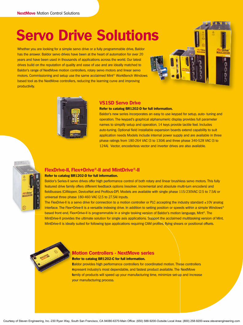
DC Servo MotorsNextMove Motion Control Solutions
Servo Drive Solutions
FlexDrive-II, Flex+Drive®-II and MintDrive®-IIRefer to catalog BR1202-D for full information.
Baldor’s Series-II servo drives offer high performance control of both rotary and linear brushless servo motors. This fully
featured drive family offers different feedback options (resolver, incremental and absolute multi-turn encoders) and
fieldbusses (CANopen, DeviceNet and Profibus-DP). Models are available with single phase 115/230VAC (2.5 to 7.5A) or
universal three phase 180-460 VAC (2.5 to 27.5A) inputs.
The FlexDrive-II is a servo drive for connection to a motion controller or PLC accepting the industry standard ±10V analog
interface. The Flex+Drive-II is a versatile indexing drive. In addition to setting position or speeds within a simple Windows®
based front end, Flex+Drive-II is programmable in a single tasking version of Baldor’s motion language, Mint®. The
MintDrive-II provides the ultimate solution for single axis applications. Support the acclaimed multitasking version of Mint,
MintDrive-II is ideally suited for following type applications requiring CAM profiles, flying shears or positional offsets.
VS1SD Servo DriveRefer to catalog BR1202-D for full information.
Baldor’s new series incorporates an easy to use keypad for setup, auto- tuning and
operation. The keypad’s graphical alphanumeric display provides full parameter
names to simplify setup and operation, 14 keys provide tactile feel. Includes
auto-tuning. Optional field installable expansion boards extend capability to suit
application needs Models include internal power supply and are available in three
phase ratings from 180-264 VAC (3 to 130A) and three phase 340-528 VAC (3 to
124A). Vector, encoderless vector and inverter drives are also available.
Servo Drive Solutions
Motion Controllers - NextMove seriesRefer to catalog BR1202-C for full information.
Baldor provides high performance controllers for coordinated motion. These controllers
represent industry’s most dependable, and fastest product available. The NextMove
family of products will speed up your manufacturing time, minimize set-up and increase
your manufacturing process.
Whether you are looking for a simple servo drive or a fully programmable drive, Baldor
has the answer. Baldor servo drives have been at the heart of automation for over 20
years and have been used in thousands of applications across the world. Our latest
drives build on the reputation of quality and ease of use and are ideally matched to
Baldor’s range of NextMove motion controllers, rotary servo motors and linear servo
motors. Commissioning and setup use the same acclaimed Mint® WorkBench Windows
based tool as the NextMove controllers, reducing the learning curve and improving
productivity.
Motion Controllers - NextMove seriesRefer to catalog BR1202-C for full information.
Baldor provides high performance controllers for coordinated motion. These controllers
represent industry’s most dependable, and fastest product available. The NextMove
family of products will speed up your manufacturing time, minimize set-up and increase
Courtesy of Steven Engineering, Inc.-230 Ryan Way, South San Francisco, CA 94080-6370-Main Office: (650) 588-9200-Outside Local Area: (800) 258-9200-www.stevenengineering.com
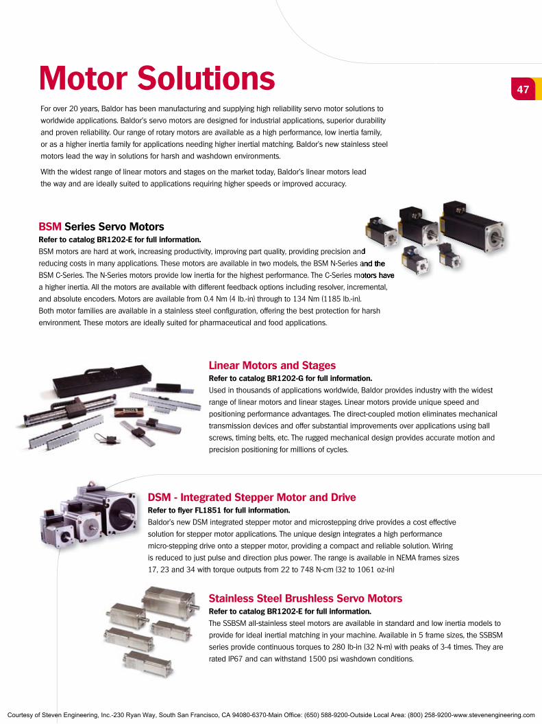
47Motor SolutionsFor over 20 years, Baldor has been manufacturing and supplying high reliability servo motor solutions to
worldwide applications. Baldor’s servo motors are designed for industrial applications, superior durability
and proven reliability. Our range of rotary motors are available as a high performance, low inertia family,
or as a higher inertia family for applications needing higher inertial matching. Baldor’s new stainless steel
motors lead the way in solutions for harsh and washdown environments.
With the widest range of linear motors and stages on the market today, Baldor’s linear motors lead
the way and are ideally suited to applications requiring higher speeds or improved accuracy.
BSM Series Servo MotorsRefer to catalog BR1202-E for full information.
BSM motors are hard at work, increasing productivity, improving part quality, providing precision and
reducing costs in many applications. These motors are available in two models, the BSM N-Series and the
BSM C-Series. The N-Series motors provide low inertia for the highest performance. The C-Series motors have
a higher inertia. All the motors are available with different feedback options including resolver, incremental,
and absolute encoders. Motors are available from 0.4 Nm (4 lb.-in) through to 134 Nm (1185 lb.-in).
Both motor families are available in a stainless steel configuration, offering the best protection for harsh
environment. These motors are ideally suited for pharmaceutical and food applications.
Linear Motors and StagesRefer to catalog BR1202-G for full information.
Used in thousands of applications worldwide, Baldor provides industry with the widest
range of linear motors and linear stages. Linear motors provide unique speed and
positioning performance advantages. The direct-coupled motion eliminates mechanical
transmission devices and offer substantial improvements over applications using ball
screws, timing belts, etc. The rugged mechanical design provides accurate motion and
precision positioning for millions of cycles.
DSM - Integrated Stepper Motor and DriveRefer to flyer FL1851 for full information.
Baldor’s new DSM integrated stepper motor and microstepping drive provides a cost effective
solution for stepper motor applications. The unique design integrates a high performance
micro-stepping drive onto a stepper motor, providing a compact and reliable solution. Wiring
is reduced to just pulse and direction plus power. The range is available in NEMA frames sizes
17, 23 and 34 with torque outputs from 22 to 748 N-cm (32 to 1061 oz-in)
Stainless Steel Brushless Servo MotorsRefer to catalog BR1202-E for full information.
The SSBSM all-stainless steel motors are available in standard and low inertia models to
provide for ideal inertial matching in your machine. Available in 5 frame sizes, the SSBSM
series provide continuous torques to 280 lb-in (32 N-m) with peaks of 3-4 times. They are
rated IP67 and can withstand 1500 psi washdown conditions.
BSM motors are hard at work, increasing productivity, improving part quality, providing precision and
reducing costs in many applications. These motors are available in two models, the BSM N-Series and the
BSM C-Series. The N-Series motors provide low inertia for the highest performance. The C-Series motors have
Courtesy of Steven Engineering, Inc.-230 Ryan Way, South San Francisco, CA 94080-6370-Main Office: (650) 588-9200-Outside Local Area: (800) 258-9200-www.stevenengineering.com

Copyright © Baldor Electric Company 2005. All trademarks recognized. Specifications subject to change without notice.
Local Distributor:
Baldor's Motion Solutions CatalogsBR1202-A Motion Control Solutions
BR1202-B Mint® Software and Applications
BR1202-C NextMove Multi-Axis Motion Controllers
BR1202-D AC Servo Drives
BR1202-E AC Servo Motors
BR1202-F DC Servo Motors and Drives
BR1202-G Linear Motors and Stages
BR1202-H Motion Product Accessories
BR1202-I Real-Time Ethernet Motion Solutions
World Headquarters (U.S.A.) Baldor Electric Company Tel: +1 479 646-4711 Fax: +1 479 648-5792 E-mail: [email protected]
Australia Tel: +61 2 9674 5455 Fax: +61 2 9674 2495 E-mail: [email protected]
China Phone: +86-21-64473060 Fax: +86-21-64078620 E-mail: [email protected]
Germany Tel: +49 89 905 08-0 Fax: +49 89 905 08-490 E-mail: [email protected]
India Tel: +91 20 25 45 27 17/18 Fax: +91 20 25 45 27 19 E-mail: [email protected]
Italy Tel: +41 91 640 9950 Fax: +41 91 630 2633 E-mail: [email protected]
Japan Tel: +81 45-412-4506 Fax: +81 45-412-4507 E-mail: [email protected]
Korea Tel: +(82-32) 508 3252 Fax: +(82-32) 508 3253 E-mail: [email protected]
Mexico Tel: +52 477 761 2030 Fax: +52 477 761 2010 E-mail: [email protected]
Singapore Tel: +65 744 2572 Fax: +65 747 1708 E-mail: [email protected]
Switzerland Tel: +41 52 647 4700 Fax: +41 52 659 2394 E-mail: [email protected]
United Kingdom Tel: +44 1454 850000 Fax: +44 1454 859001 E-mail: [email protected]
For additional office locations visit
www.baldor.com
BR1202-F 06/0910,000 TCP U.S.A.
Courtesy of Steven Engineering, Inc.-230 Ryan Way, South San Francisco, CA 94080-6370-Main Office: (650) 588-9200-Outside Local Area: (800) 258-9200-www.stevenengineering.com