axial flow valves am
TRANSCRIPT

300 and 600 Series – 2" thru 12"
Axial Flow ValvesOperation, Control Manifold, Capacity Limiter,
Control Loops, Installation and Repair Parts List
IMP 9710.5

AMERICAN METER COMPANY FIVE-YEAR LIMITED WARRANTYIndustrial Regulators
American Meter Company Industrial Products Division (hereinafter referred to as “the Company”) supplies IndustrialRegulators of high quality, materials, and workmanship. The Company will correct any defect(s) of workmanshipoccurring during the period of one year after shipment (the “Warranty Start Date”) providing the Purchaser hasgiven the Company immediate written notice of the defects.In addition, a Five-Year Warranty to the original owner in a permanent regulator installation is offered against structural failure, and for individual components (list furnished by writing our general offices) from the WarrantyStart Date under normal use, operation, and maintenance.The Company obligation under this warranty is limited at its option to repayment of the purchase price, repair orfurnishing of a similar part upon inspection and confirmation of the defective condition.THERE ARE NO OTHER WARRANTIES, EITHER EXPRESSED OR IMPLIED, AND ANY OTHER WARRANTIES AREHEREBY DISCLAIMED.A full copy of the American Meter Company Warranty may be obtained by writing our general offices. Laws of theCommonwealth of Pennsylvania are applicable to this warranty.
WARNING
OUTSIDE Axial Flow Valve installations require that care is taken to prevent pilot vent openings from freezingclosed or becoming blocked or allowing water to enter (from any cause). Particular consideration should be givento sites where flooding, freezing, snow, or freezing rain may be experienced. Additional overhead protection of thepilot regulator from weather and/or flooding should be used where necessary.
WARNING
Axial Flow Valves are engineered to accurately control natural gas and other approved gases. Axial Flow Valves and all related Control System Components require clean, dry, non-aggressive gases for proper function – gasstreams containing liquids, hydrates, hydrogen sulfates, and other contaminants may shorten Axial Flow Valve and related Control System Components life, and may inhibit proper function.Please consult your American Meter Company representative if there is a question of compatability of any gascomposition, or contact us through our website: www.americanmeter.com

BASIC CONTROL LOOPS – OPERATIONSingle-Stage Pressure-Reducing Regulator . . . . . . . . .8Two-Stage Pressure Reduction . . . . . . . . . . . . . . . . . . .9Relief Valve and Back-Pressure Regulation . . . . . . . . .9Worker/Monitor with Downstream Monitoring . . . . . .10Passive Upstream Monitoring . . . . . . . . . . . . . . . . . . .11Two-Stage Regulation with Monitor Override . . . . . . .12Pressure-Reducing Regulator with Controller . . . . . . .13Back-Pressure Regulation with Controller . . . . . . . . .14Internal Manifold Plug Installation Instructions . . . . . .15
INSPIRATOR CONTROL MANIFOLD Retrofit Installations . . . . . . . . . . . . . . . . . . . . . . . . . . .16New Installations . . . . . . . . . . . . . . . . . . . . . . . . . . . . .16Initial Setup, Single-Stage Pressure Reduction . . . . .16Initial Setup, Worker/Monitor Pressure Reduction . . .17Initial Setup, Back Pressure and Relief . . . . . . . . . . . .17Manifold Inspection and Maintenance . . . . . . . . . . . .18Worker Manifold Plug Installation . . . . . . . . . . . . . . . .18
AXIAL FLOW VALVES – MAINTENANCEComponents . . . . . . . . . . . . . . . . . . . . . . . . . . . . . . . .19Disassembly . . . . . . . . . . . . . . . . . . . . . . . . . . . . . . . . .20Inspection . . . . . . . . . . . . . . . . . . . . . . . . . . . . . . . . . .21Reassembly . . . . . . . . . . . . . . . . . . . . . . . . . . . . . .21-22Storage . . . . . . . . . . . . . . . . . . . . . . . . . . . . . . . . . . . .22Sleeve Data Stamp . . . . . . . . . . . . . . . . . . . . . . . . . . .22
AXIAL FLOW VALVES – REPAIR PARTS AND ACCESSORIESStud Bolts and Nuts-300 Series . . . . . . . . . . . . . . . . .23Stud Bolts and Nuts-600 Series . . . . . . . . . . . . . . . . .23Accessories . . . . . . . . . . . . . . . . . . . . . . . . . . . . . . . . .23Sizes and Weights . . . . . . . . . . . . . . . . . . . . . . . . . . . .23Axial Flow Valve 300-Series . . . . . . . . . . . . . . . . . . . .24Axial Flow Valve 600-Series . . . . . . . . . . . . . . . . . . . .25Control Loop Assemblies . . . . . . . . . . . . . . . . . . . . . .26
WARNING
The standard Buna N sleeve (American Meter codes B5, B5-L and B7) contains no hazardous ingredients thatwould be considered harmful to a person handling the sleeve.However, it has been determined that the surface of the optional hydrin sleeve (American Meter codes H5, H5-Land H7) contains traces of dioctyl phthalate, a molding agent.Rubber gloves and an apron should be worn, and you should refrain from eating, drinking and smoking while handling hydrin sleeves.After handling the hydrin sleeves, the rubber gloves should be washed or discarded, and you should wash yourhands thoroughly to safeguard against the ingestion of the above mentioned chemical. Additional information is available through American Meter Company in Material Safety Data Sheets for dioctylphthalate, as produced by the chemical supplier, before the hydrin sleeve is molded. American Meter Company can supply copies of these sheets to our customers upon request per the OSHA Hazard Communication Standard.The information contained herein is based on data available to us and is believed to be correct. However, AmericanMeter company makes no warranty regarding the accuracy of this data or the results to be obtained from the usethereof. American Meter Company assumes no responsibility for the injury from the use of this product.
1
Table Of Contents
AXIAL FLOW VALVESInterchangeable Valve-Cage Closures . . . . . . . . . . . . .2The Valve Body . . . . . . . . . . . . . . . . . . . . . . . . . . . . . . .2The Expansible Sleeve . . . . . . . . . . . . . . . . . . . . . . . . .2Trim . . . . . . . . . . . . . . . . . . . . . . . . . . . . . . . . . . . . . . . .2Bi-Directional Flow Capability . . . . . . . . . . . . . . . . . . . .2
AXIAL FLOW VALVE OPERATIONControl Passages . . . . . . . . . . . . . . . . . . . . . . . . . . . . . .3Closed Position . . . . . . . . . . . . . . . . . . . . . . . . . . . . . . .3Throttling . . . . . . . . . . . . . . . . . . . . . . . . . . . . . . . . . . . .3Open Position . . . . . . . . . . . . . . . . . . . . . . . . . . . . . . . .3
VALVE OPERATORSOn-Off . . . . . . . . . . . . . . . . . . . . . . . . . . . . . . . . . . . . . .4Throttling . . . . . . . . . . . . . . . . . . . . . . . . . . . . . . . . . . . .4Self-Operated . . . . . . . . . . . . . . . . . . . . . . . . . . . . . . . .4Controllers . . . . . . . . . . . . . . . . . . . . . . . . . . . . . . . . . . .4
INSPIRATOR CONTROL MANIFOLDManifold for Low Differential Pressures . . . . . . . . . . . .5Axial Flow Operating Pressures . . . . . . . . . . . . . . . . . .5
CAPACITY LIMITERKit Installation . . . . . . . . . . . . . . . . . . . . . . . . . . . . . . . .6Capacity Limiter Removal . . . . . . . . . . . . . . . . . . . . . . .6Capacity Limiter Kits . . . . . . . . . . . . . . . . . . . . . . . . . . .6
BASIC CONTROL LOOPSValve Operation . . . . . . . . . . . . . . . . . . . . . . . . . . . . . . .7Valve Downstream Bleed . . . . . . . . . . . . . . . . . . . . . . . .7Pilot Function – Pressure Regulation Service . . . . . . . .7Pilot Function – Back Pressure Service . . . . . . . . . . . .7Restrictor Function and Setting . . . . . . . . . . . . . . . . . .7
BASIC CONTROL LOOPS – INSTALLATIONAxial Flow Valve . . . . . . . . . . . . . . . . . . . . . . . . . . . . . . .8

2
Axial Flow Valves The Axial Flow Valve consists of three major structuralcomponents and a single moving part. Its unique,wafer design makes it unusally compact, light weightand easy to handle. (Figure 1)
Interchangeable Valve-Cage ClosuresEach consists of a center barrier, the cage with radialslots, and the clossure with communicating passages.The cage closures are investment cast 17-4 stainlesssteel.
The Valve BodyThe axial flow valve steel body is an inside contoured,cylindrical pressure containing housing. A controlgallery manifold is welded to the outside of the body.
The Expansible SleeveThe standard sleeve, the single moving part, is moldedfrom Buna N, known for its resistance to various fuelsand oils and for its retention of physical properties overa wide temperature range. The sleeve functions are:• to provide throttling action in response to pressure
differential changes;• to form the closing seal over the cage barrier;• to provide a closing preload against cages;• to separate the control chamber from the flowing
medium; and• to provide a contaminant seal between the valve
body and the cage closures.
The Buna N sleeve is sufficiently elastic for a widerange of applications and strong enough for high-pressure operation. The 70 durometer sleeve has therefore been selected as standard. The code numberfor the 70 durometer standard sleeve is B-7.
The 50 durometer sleeve, though more elastic, is notas rugged as the 70 durometer sleeve and limited tolower pressure applications. The code number for 50durometer is B-5
Other sleeve materials are available for special applications. See pages 24 and 25.
A single bolt secures the valve assembly while the centerbarrier seal is completed by the O-Ring seal under thefairing nut. The upstream and downstream cage pres-sure passages are sealed by roll pin O-rings againstthe body gallery. The roll pins align the cage closuresand the valve body with respect to one another.
TrimValve trim includes all components which come intocontact with the flowing fluid and are constructed fromthe following materials:
Buna N: O-ringsBuna N (or as specified): sleeveStainless Steel: cage closures, bolts, washer, fairing
nut and roll pins
Bi-Directional Flow CapabilityThe symmetry of the Axial Flow Valve permits controlof flow equally well in both directions and is reversibleto obtain extended service life. The fairing nut is placedon the downstream side of the valve to contribute to auniform flow path.
Figure 1Axial Flow Valve ComponentsThree Major Structural Parts and One Moving Part
Rubber Sleeve – Single Moving Part
Roll Pinand O-Ring Interchangeable
Valve-Cage Closure
O-Ring
Fairing Nut
Valve Body
Bolt
Washer
Control Gallery Manifold
InterchangeableValve-Cage Closure
Roll Pinand O-Ring

3
Axial Flow Valve – OperationControl Passages (Figure 2)The gallery of the valve body has three passages:
1. The inlet pressure normally supplies the control pressure. The inlet supply pressure passage is in the upstream closure and connects with the gallery.
2. The control passage branches into two annulargrooves in the valve body. The annular grooves distribute control pressure around the sleeve whenthe sleeve is in the fully open or closed position.
3. The exhaust or downstream bleed passage is normally used to permit reduction in control pressurewhen opening the valve. The aspirating capability ofthis passage insures a fully expanded sleeve withminimal pressure differential.
Axial Flow Valve ComponentsThree Major Structural Parts and One Moving Part
Closed Position (Figure 3)The sleeve is molded to a smaller diameter than the cage diameter. When assembled in the valve, thesleeve exerts a closing preload on the upstream anddownstream cages. The inner upstream surface of the sleeve is exposed to inlet pressure applied.
Control pressure (supplied by and equal to the inletpressure) is against the exterior of the sleeve. The differential pressure on the upstream portion of thesleeve is 0 psi, but the sleeve preload exerts a closingforce. The differential across the downstream portion of sleeve is the difference between the upstream anddownstream presures. This differential plus the sleevepreload provides the closing force.
Throttling (Figure 4)To open the valve, control pressure must be reduced. A small decrease in the control pressure permits inletpressure to lift the sleeve from the inlet cage. As thecontrol pressure is further decreased, the central sleevepreload is overcome and the sleeve is peeled progres-sively away from the downstream cage. Flow throughthe valve commences when the tapered openings ofthe outlet cage are uncovered. Further decreases incontrol pressure uncover a greater area of the outlet cage.Throttling control is maintained when the control pressurereaches equilibrium and flow demand is satisfied.
Open Position (Figure 5)The valve is fully open when the drop in control pressureis sufficient to completely expose the slots in thedownstream cage, and the sleeve is fully expandedagainst the body inner contour.
The control pressure drop is aided by aspiration throughthe downstream bleed aspiration port. At high rates offlow, the aspirated pressure in the bleed channel can besignificantly lower than the downstream pipe line pres-sure, thereby minimizing the differential between inletand outlet pressures required for full valve opening.
Figure 3Closed Position
Figure 4Throttling Position
Figure 5Open Position
Figure 2
Cage
Sleeve
Inlet Pressure
Control Pressure
Exhaust or Downstream Bleed
Cage
Sleeve
Inlet Pressure
Control Pressure
Exhaust or Downstream Bleed
Cage
Sleeve
Inlet Pressure
Control Pressure
Exhaust or Downstream Bleed
InletPressure
OutletPressure
BodySleeve
ControlGalley
DownstreamCage
UpstreamCage
DownstreamCage
CenterBarrier
ControlPressureInlet
SupplyPressure
ExhaustDownstreamBleed
Flow
Flow
UpstreamCage

P1
Valve AClose
Valve BOpen
InletPressure
OutletPressure P2
BodySleeve
Control PressureExhaust OrDownstream Bleed
ControlGalley
DownstreamCage
InletSupply
Pressure
UpstreamCage
UpstreamCage
DownstreamCage
CenterBarrier
Pc
4
Valve Operators (Figure 6)The Axial Flow Valve is essentially a pneumatic orhydraulic motor valve. To function, the basic valverequires some type of a valve operator.
The Axial Flow Valve is normally closed (if control andinlet pressure are equal). When closed, the closingforces are control chamber pressure acting on thesleeve exterior plus the elastic preload. The openingforces are inlet pressure acting on the interior of thesleeve through the inlet cage. To crack the valve, control pressure must be decreased so that inlet pres-sure can overcome the initial preload. To open thevalve further, control pressure must be reduced. Toopen the valve fully, control pressure must be reduceduntil inlet pressure has fully expanded the sleeve. Anyfurther reduction of control pressures does not affectthe valve operation. See page 5 for table of operatingpressures.
To change the control chamber pressure, two externalvalves are required.
Valve A controls the supply pressure. Usually, inletpressure is used to supply control chamber pressure.Control chamber pressure closes the valve. In themajority of application, Valve A is an adjustable, non-closing restrictor.
Valve B adjusts control chamber pressure and positionsthe sleeve. Valve B is usually a pilot pressure regulator.
A three-way connector is required to make connectionsto Valve A, Valve B and to control chamber.
On-OffFor On-Off applications, an adjustable restrictor is usedfor Valve A, and Valve B can be open or closed.
Manually – by means of handler buttons, levers or footpedals;Automatically – by means of electrical operated solenoids,mechanically operated lever or cams and motors.
ThrottlingThrottling applications require the feedback of pressurewhich is utilized in controlling the position of Valve B.
Self-OperatedSelf-operated applications are used in pressure control.Sensed pressure (downstream) is used for pressurereducing regulation. Sensed pressure (upstream) is used for relief valve and back pressure service.
ControllersControllers are used when precision control is requiredfor severe operating conditions. Many combinations ofpilots and pneumatic controllers can be used for flow,pressure, temperature, or process control. A controllerdoes not normally act directly to position the sleeve butrather must act through a “pilot” or diaphragm motorvalve interface.
Figure 6Axial Flow Valve with Manual Operator
Reduced ControlPort Pressure OPENSAxial Flow Valve

5
Inspirator Control ManifoldManifold For Low Differential PressureWhen equipped with an optional Inspirator ControlManifold, the American Axial FlowTM Valve providesaccurate and proven pressure regulation in applicationswith very low differential pressures. The manifoldextends the operating range of the AFV at low inletpressures while maintaining the same maximum operating pressure ratings.
The Axial Flow Valve uses an elastomer sleeve whichexpands or contracts depending on the pressure differ-ential across the sleeve. Once this differential exceedsthe minimum cracking pressure, the sleeve expandsallowing flow through the valve until downstreamdemand is supplied and the pressure is balancedacross the sleeve.
With a conventional restrictor-type control manifold, thesleeve differential pressure cannot be greater than thetotal pressure drop across the valve. In some peak loadapplications, the inlet pressure can be reduced to thepoint where there is not a sufficient differential betweenthe inlet and the outlet (set) pressure to allow the valveto fully open. Or, in high-pressure applications, the differential needed to fully open the valve may begreater than the available drop across the valve.
the Inspirator Control Manifold incorporates a speciallydesigned nozzle (Figure 7). This nozzle reduces thesleeve control pressure (Pc) so that the differentialacross the sleeve (P1-Pc) is approximately three timesthe differential across the valve (P1-P2). The InspiratorControl Manifold, in essence, acts like a differentialpressure amplifier with a gain of three. The maximumdifferential which the inspirator can generate is approximately 62% of the absolute inlet pressure. The adjustable restrictor shown is used to vary theresponse time of the sleeve. (Tune for stability.)
The Inspirator Control Manifold extends the applicationrange of Axial Flow Valves by reducing the differentialpressure necessary to fully open the valve while main-taining the control sensitivity and control pressureaccuracy. The inspirator control can be used in singlevalve pressure reduction applications and also in worker/monitor sets where the combined pressure loss is generally higher, resulting in less differential per valve.The Inspirator Control Manifold can be supplied forretrofit to Axial Flow Valves in the field or can beordered in place of the standard composite block manifold for new installations.
InspiratorManifold
Inspirator
-Pc
AdjustableRestrictor
P1 P2
Figure 7 – Inspirator Manifold Mounted on AFV
Composite BlockManifold Operating Parameters
Inspirator BlockManifold Operating Parameters
MaximumOperating Conditions
Cracking Full Open Cracking Full Open Continuous Intermittent **AFV
SeriesSleeve
Number
300 5L 1.5 psid 5 psid 0.5 psid 1.7 psid 30 psid 50 psid
300 5 3.5 psid 15 psid 1.5 psid 7.5 psid 125 psid 180 psid
300 7 14 psid 30 psid 6 psid 19 psid 500 psid 720 psid
600 * 7 30 psid 60 psid 12 psid 25 psid 1000 psid 1440 psid
* Series 600 available in 2", 4", 6" and 8" only.** Intermittent is defined as total time in service ! 30 days at this intermittent pressure.
Axial Flow Valve Operating Pressures

6
Capacity Limiter KitThis Capacity Limiter Kit (Figure 8) is supplied as an option for 2", 3", and 4" standard trim Axial FlowValves to reduce the full-open capacity to a predeter-mined percentage of its rated capacity.
Two kits are available to reduce the capacity of an AxialFlow Valve to either 50% or 75% of the valve’s ratedcapacity. Each kit consists of a bolt, a spacer and theLimiter. The flat faces of the Limiter are stamped with a number that reads 2-300-50 or 2-300-75. Check yourCapacity Limiter to be certain it is correct for theintended application.
Additional and/or custom size limiters are availableupon request.
Kit Installation Instructions• If the kit is for an AFV, remove the valve from the line.
• Disassemble bolt, washer and fairing nut. Save thebolt and washer in the event future requirementsnecessitate a return to 100% capacity.
• Assemble Limiter and spacer on new bolt with thedesired 300 or 600 designation facing upstream.Install bolt in upstream end of valve as shown inFigure 8. Do NOT use a washer. The faces of theLimiter and the AFV must be flush within .03". Animproperly assembled 2" Capacity Limiter will eitherproject out beyond the AFV flange or be recessed by about .190".
• Check that O-ring is seated in fairing nut groove.Assemble nut and tighten to:
2" and 3" torque to 20 to 30 ft*lbs4" torque to 40 to 60 ft*lbs6" torque to 75 to 100 ft*lbs
• Affix the appropriate label to AFV body just below the existing badge. If valve body is dirty, clean beforeapplication.
• Reassemble AFV to line.
Capacity Limiter Removal (2" Example)• Depressurize and remove AFV from line.
• Disassemble bolt, Limiter, spacer and fairing nut.
• Install original 1.37" long bolt and washer.
• Remove the reduced capacity label.
• Reassemble AFV to line.
Capacity Limiter Kits for Axial Flow Valves
Percent Class 300 Class 600Valve of Full-Open Part PartSize Capacity Number Number
2" AFV 50% 74075G036 74075G0362" AFV 75% 74075G041 74075G041
3" AFV 50% 74075G055 N.A.3" AFV 75% 74075G060 N.A.
4" AFV 50% 74075G074 74075G0934" AFV 75% 74075G079 74075G098
6" AFV 50% 74075G112 N.A.6" AFV 75% 74075G117 N.A.
Figure 8Installation drawing showing proper position of Capacity Limiter for 300 and 600 Series.
CapacityLimiter
BoltSpacer
Inlet Side Inlet Side
CapacityLimiter
BoltSpacer
300 Series 600 Series
Capacity Limiter Kit
Axial FlowValve
InspiratorControl Manifold
FlowArrows
ValveInlet

DownstreamStaticSensingLine
AdjustableRestrictorFilterElementINLET SUPPLY PRESSURE
OUTLET PRESSURE
Upstream Cage
Sleeve Body
Downstream Cage
CONTROL PRESSURE
Exhaust -DownstreamBleed
CenterBarrier
UpstreamStaticSensingLine
AdjustableRestrictorFilterElementINLET SUPPLY PRESSURE
Upstream Cage
Sleeve Body
Downstream Cage
CONTROL PRESSURE
OUTLET PRESSURE
Exhaust -DownstreamBleed
CenterBarrier
Pilot ReturnLine toDownstream
DownstreamStatic Sense LineConnection
Pilot Vent
Inlet Pilot Supply(PressureConnection)
Pilot Vent
DownstreamStatic SenseLineConnection
Inlet Pilot Supply(PressureConnection)Pilot
ReturnLine toDownstream Figure 9
INSPIRATOR ManifoldConnections
Figure 9COMPOSITE BlockManifold Connections
Basic AFV Control LoopsRefer to Figures 9, 10, 11
Axial Flow Valve – Valve OperationThe valve is closed when the pilot regulator is closedand the upstream pressure has equalized through therestrictor acting against the exterior of the sleeve as a valve closing force.
• The valve is closed when the control pressure isequal to the inlet pressure. • The valve begins to open when there is a reduction in control pressure which is greater than the sleevepreload. • The valve is fully open when the drop in control pressure is sufficient to permit inlet pressure to completely expand the sleeve.
Valve Downstream BleedThe valve downstream bleed on the AFV is aspirated at high rates of flow by a venturi effect. This aspirationinduces a drop in pressure in the valve downstreamport. The induced drop in pressure aids the pilot tolower the control pressure when the valve approachesfull open.
Do not use the AFV downstream bleed port for pressure sensing. A stable pressure location MUSTbe used for feedback to the pilot.
Pilot Function – Pressure Reduction Service (PR)(Figure 10)
For pressure regulation, the pilot senses downstreampressure. A demand for flow will slightly reduce down-stream pressure and will open the pilot valve. Theeffective opening of the pilot valve is regulated bychanges in the downstream pressure sensed.
Pilot Function – Back Pressure Service andRelief Valve Operation (RV) (Figure 11)
For back-pressure regulation and relief-valve operation,the pilot senses upstream pressure. An increase inupstream pressure above the dead-end shut-off†pressure causes the pilot valve to open and exhaustcontrol pressure.
The effective opening of the pilot valve is regulated by upstream pressure changes sensed.
Adjustable Restrictor Function and Setting The adjustable restrictor supplies makeup gas to theAFV control port in opposition to the gas bled away bythe pilot regulator (or motor valve). Standard compositeblock settings are typically “3”. Inspirator BlockSettings are typically 5-6. (Careful tuning is required for good control and stability.)† Dead-end shut off in this application
is called relief pressure setting. 7
Figure 11 –Relief ValveService

8
Installation (Figure 12)1. Assemble the control loop as indicated below
(Figure 12) with restrictor inlet position at theupstream of the Axial Flow Valve.
2. The Control Loop assembly may be mounted on thesmaller AFVs before the valve is mounted betweenthe pipe flanges. Three O-rings are required. (Sixwith Inspirator) The O-rings slip on the roll pins whichalign the ports in the composite manifold with theports in the Axial Flow Valve gallery.Larger Axial Flow Valves should be mountedbetween the pipe flanges before the control loop is mounted on the Axial Flow Valve.To facilitate the handling of heavier valves, a liftingplate, Part Number 73672P001, is available. The lift-ing plate is attached to the gallery on the valve bodywith the composite manifold mounting screws andhas a lifting opening (1/2" x 1-1/2") which is suitablefor engagement by a hook or cable.
3. Align the pipe flanges and insert the lower studbolts. Optional centering tubes can be placed overthe two lowest stud bolts for the 250 and 300 ANSIflange installations.
4. If the pull-up space is less than desired, use theflange separators to increase the space. The AxialFlow Valve must be installed with its fairing nut ondownstream side of the valve. Place the valve andgaskets between the flange. Place the nuts on thestud bolts.
5. Remove the flange separators (if used). Tighten thenuts evenly around the bolt circle. Assure that aminimum of one and one-half or more threads showbeyond the nut.
6. Check the control loop and system for leads toassure all the connections are tightened properlyand that no tubing has been nicked or bent.
FLOWFLOW
Figure 12AFV and ControlLoop (typical)
AFV with Composite Block ControlSingle-Stage Pressure-Reducing (PR) Regulator(Figure 13)
1. Set restrictor to maximum (No. 8) setting.2. Relax pressure spring of pilot regulator by backing
out adjustment screw until spring tension is at mini-mum.
3. Crack downstream block valve.4. Crack upstream block valve to pressurize Axial
Flow Valve (AFV).5. Fully open upstream and downstream block valves.6. Slowly increase pilot pressure spring tension until
some downstream flow is achieved.7. Reset restrictor (slowly) to No. 4 setting.8. Slowly increase pilot pressure spring tension until
downstream pressure approximates desired setpressure.
9. Tune system by alternately adjusting the pilot pressure spring and restrictor until both therequired set point and stable control is achieved at the lowest possible restrictor setting under normal flow conditions.
10. Slowly close downstream block valve to check forAFV lockup.
11. Gradually open downstream block valve.NOTE: The Composite Block adjustable restrictor controls the rate of AFV opening and closing. Low restrictor settings quicken theopening and slow the closing. Restrictor settings above 4 tend toflood the control system; therefore, high settings should be avoidedunless required for control stability. Composite Block restrictor set-tings of 2 or 3 are normal under most conditions. (Inspirator Blockrestrictor should be set at 5-6.)
AdjustableRestrictor
PilotAdjustScrew
BlockValve
Axial Flow Valve
Pilot
BlockValve
Static
Pilot With Secondary Diaph.60 Series Pilot
AdjustableRestrictor
PilotAdjustScrew
BlockValve
Axial Flow Valve
Pilot
BlockValve
Pilot W/O Secondary Diaph.1203
AdjustableRestrictor
PilotAdjustScrew
BlockValve
Axial Flow Valve
Pilot
BlockValve
Static
Pilot With Secondary Diaph.60 Series Pilot
AdjustableRestrictor
PilotAdjustScrew
BlockValve
Axial Flow Valve
Pilot
BlockValve
Pilot W/O Secondary Diaph.1203

9
AFV with Composite Block ControlTwo-Stage Pressure Reduction (PR) (Figure 14)
1. Set restrictors of both first- and second-stage regulators to maximum (No. 8) setting.
2. Relax the pressure spring of both pilot regulatorsby backing out adjustment screw until spring tension is at minimum.
3. Crack downstream block valve.4. Crack upstream block valve to pressurize Axial
Flow Valve (AFV).5. Fully open upstream and downstream block valves.6. Slowly increase pilot pressure spring tension of
first-stage until approximate desired intermediatepressure is indicated to inlet of second stage.
7. Slowly reset first-stage restrictor to No. 4 setting.8. Slowly increase pilot pressure spring tension of
second-stage regulator until approximate down-stream pressure is achieved.
9. Gradually reset second-stage restrictor to No. 4setting.
10. Tune first-stage regulator by alternately adjustingthe pilot pressure spring and restrictor until boththe required set point and stable control isachieved at the lowest possible restrictor settingunder normal flow conditions.
11. Tune second-stage regulator in same manner.12. Close downstream block valve to check for AFV
lockup.13. Gradually open downstream block valve.NOTE: The Composite Block adjustable restrictor controls the rate of AFV opening and closing. Low restrictor settings quicken theopening and slow the closing. Restrictor settings above 4 tend toflood the control system; therefore, high settings should be avoidedunless required for control stability. Composite Block restrictor set-tings of 2 or 3 are normal under most conditions. (Inspirator Blockrestrictor should be set at 5-6.)
AdjustableRestrictor
PilotAdjustable Screw
BlockValve 1st Stage
Regulator
Pilot
Static
AdjustableRestrictor
PilotAdjustableScrew
2nd StageRegulator
Pilot
BlockValve
AFV with Composite Block ControlRelief Valve (RV) and Back-Pressure Regulation (Figure 15)
1. Set restrictor to maximum (No. 8) setting.2. Increase pressure spring tension of pilot regulator
by turning adjusting screw inward until maximumtension is attained.
3. Open downstream block valve (if used).4. Gradually introduce inlet pressure to the AFV.5. Gradually decrease pilot pressure spring tension until:
Back pressure – some downstream flow is achievedRelief valve – the desired set point is reached.
6. Reset restrictor to:Back pressure – No. 4 settingRelief valve – the correct restrictor setting is deter-mined at time of installation. Use the lowest restrictorsetting which permits the Axial Flow Valve to reseatat a pressure greater than the normal line pressure.Settings from No. 3 to No. 4 are normal.
7. Back pressure only – slowly decrease pilot-pressurespring tension until upstream pressure approximatesdesired set pressure.
8. Back pressure only – tune system by alternatelyadjusting the pilot pressure spring and restrictoruntil both required set point and stable control isachieved at the lowest possible restrictor settingunder normal flow conditions.
NOTE: The Composite Block adjustable restrictor controls the rate of AFV opening and closing. Low restrictor settings quicken theopening and slow the closing. Restrictor settings above 4 tend toflood the control system; therefore, high settings should be avoidedunless required for control stability. Composite Block restrictor set-tings of 2 or 3 are normal under most conditions. (Inspirator Blockrestrictor should be set at 5-6.)
AdjustableRestrictor
PilotAdjustable Screw
BlockValve
Axial Flow Valve
Pilot
BlockValve
Static

1. Set restrictors of both worker and monitor to maximum (No. 8) setting.
2. Relax pressure spring of monitor pilot regulator by backing out the adjustment screw until springtension is at minimum.
3. Increase pressure spring tension of worker pilotregulator to maximum by turning adjusting screwinward.
4. Crack downstream valve slightly open.5. Slowly crack upstream block valve open to
pressurize Axial Flow Valves.6. Fully open upstream and downstream block valves.7. Reset monitor restrictor to No. 4 setting.8. Reset worker restrictor to No. 2 setting9. Slowly increase monitor pilot pressure spring
tension until downstream pressure approximatesdesired monitor set pressure.
NOTE: See table below of suggested monitor/regulator set point differentials.
AdjustableRestrictor
PilotAdjustScrew
BlockValve Worker
AFV
Pilot
BlockValve
WorkerStatic
AdjustableRestrictor
MonitorAFV
PilotAdjustScrew
MonitorStatic
InternalPlug*
Working Regulator Monitor RegulatorSet Points Set Points
8" w.c. to 28" w.c. 2" to 5" w.c. above worker
1 psig to 5 psig 1/4 to 3/4 psig above worker
5 psig to 10 psig 1/2 to 1 psig above worker
10 psig to 30 psig 1 to 2 psig above worker
30 psig – Up 5% of maximum adjustment above worker set pressure
Set Pressure Differentials
10. Tune monitor by alternately adjusting the pilot pressure spring and restrictor until both therequired set point and stable control are achieved at the lowest possible restrictor setting under normal flow conditions.
11. Reset worker restrictor to No. 4 setting.12. Slowly decrease worker pilot pressure spring ten-
sion until worker regulator assumes control and thedownstream pressure approximates desired workerset pressure.
13. Tune worker in same manner as outlined in Step 10.14. Close downstream block valve to check for AFV lockup.15. Gradually open downstream block valve.* See Internal Plug Installation, Figure 21 on page 15.
NOTE: The Composite Block adjustable restrictor controls the rate of AFV opening and closing. Low restrictor settings quicken theopening and slow the closing. Restrictor settings above 4 tend toflood the control system; therefore, high settings should be avoidedunless required for control stability. Composite Block restrictor set-tings of 2 or 3 are normal under most conditions. (Inspirator Blockrestrictor should be set at 5-6.)
10
AFV with Composite Block ControlWorker/Monitor with DownstreamMonitoring (Figure 16)
Table of Suggested Set Points for Worker and Monitor Regulators

Setting Worker in Service1. Set restrictors of both worker and monitor to
maximum No. 8 setting.2. Relax pressure spring of worker pilot regulator
by backing out the adjustment screw until springtension is at minimum.
3. Increase pressure spring tension of monitor pilot to maximum by turning adjusting screw inward.
4. Crack downstream block valve.5. Slowly crack upstream block valve to pressurize
Axial Flow Valve (AFV).6. Fully open upstream and downstream block valves.7. Reset monitor restrictor to No. 2.8. Slowly increase pilot pressure spring tension of
worker until some downstream flow is achieved.9. Slowly reset worker restrictor less than No. 4 setting.
10. Slowly increase worker pilot pressure spring tension until downstream pressure approximatesdesired worker set pressure.
11. Tune AFV worker by alternately adjusting the pilot pressure spring and restrictor until both therequired set point and stable control are achievedat the lowest possible restrictor setting under normal flow conditions.
Setting Monitor in Service1. Slowly decrease monitor pilot pressure spring tension
until it begins to assume control from the worker.2. Fail worker wide open by disconnecting sense line
or increasing set point above desired monitor setpressure.
3. Tune monitor by alternately adjusting pilot pressurespring and restrictor until both the required set pointand stable control is achieved at the lowest possiblerestrictor setting under normal flow conditions.
4. Place worker back in operation by reversing actionStep 2 above.
5. Close downstream block valve to check for AFVlockup.
6. Gradually open downstream block valve.
NOTE: The Composite Block adjustable restrictor controls the rate of AFV opening and closing. Low restrictor settings quicken theopening and slow the closing. Restrictor settings above 4 tend toflood the control system; therefore, high settings should be avoidedunless required for control stability. Composite Block restrictor set-tings of 2 or 3 are normal under most conditions. (Inspirator Blockrestrictor should be set at 5-6.)
* See Internal Plug Installation,Figure 21 on page 15.
*
11
Working Regulator Monitor RegulatorSet Points Set Points
8" w.c. to 28" w.c. 2" to 5" w.c. above worker
1 psig to 5 psig 1/4 to 3/4 psig above worker
5 psig to 10 psig 1/2 to 1 psig above worker
10 psig to 30 psig 1 to 2 psig above worker
30 psig – Up 5% of maximum adjustment above worker set pressure
Set Pressure Differentials
Table of Suggested Set Points for Worker and Monitor Regulators
AFV with Composite Block ControlWorker/Monitor with PassiveUpstream Monitoring (Figure 17)
AdjustableRestrictor
PilotAdjustScrew
BlockValve Worker
AFV
Pilot
BlockValve
WorkerStatic
AdjustableRestrictor
MonitorAFV
PilotAdjustScrew
MonitorStatic
InternalPlug

Setting Monitor Override in Service1. Slowly decrease monitor override pilot-pressure
spring tension until it begins to assume controlfrom the second-stage regulator.
2. Fail second-stage regulator wide open by disconnecting the second-stage pilot static line or increasing set point above desired monitor set pressure.
3. Adjust monitor override pilot pressure spring todesired monitor set point without adjusting first-stage restrictor as set in Step 8 above.
4. Place worker back in operation by reversing actionStep 2.
5. Close downstream block valve to check for AFVlockup.
6. Gradually open downstream block valve.
NOTE: The Composite Block adjustable restrictor controls the rate of AFV opening and closing. Low restrictor settings quicken theopening and slow the closing. Restrictor settings above 4 tend toflood the control system; therefore, high settings should be avoidedunless required for control stability.A numerically combined restrictor setting total is limited to 3-1/2when two pilots share a single aspirator port and full open AFVs arerequired at minimum pressure drops.Complete lockup of station will not be achieved until the secondstage outlet pressure (P2) reaches the lockup pressure of the over-ride pilotComposite Block restrictor settings of 2 or 3 are normal under mostconditions.
12
• The maximum inlet pressure (P1) for this system is limited to themaximum first-stage pilot spring adjustment of the highest standardspring range (325 PSIG for 60L-PR pilots).
1. Set restrictors of both first- and second-stage regulators to maximum No. 8 setting.
2. Relax pressure spring of both first-and second-stage pilot regulators by backing out adjustmentscrew until spring tension is at minimum.
3. Increase pressure-spring tension of override pilot to maximum by turning adjusting screw inward.
4. Crack downstream block valve.5. Crack upstream block valve to pressurize Axial
Flow Valve (AFV).6. Fully open upstream and downstream block valves.7. Slowly increase pilot pressure of first stage until
approximate desired intermediate pressure is indicated to the inlet of second stage.
8. Slowly reset first-stage restrictor to No. 4 setting.9. Slowly increase pilot-pressure spring tension of
second-stage regulator until approximate down-stream pressure is achieved.
10. Gradually reset second-stage restrictor to No. 4setting.
11. Tune first-stage regulator by alternately adjustingthe pilot-pressure spring and restrictor until boththe required set point and stable control areachieved at the lowest possible restrictor settingunder normal flow conditions.
12. Tune second-stage regulator in the same manner.
AdjustableRestrictor
1st StageRegulatorMonitor
BlockValve
BlockValve2nd Stage
Regulator
AdjustableRestrictor
P2
P3P1Static
2nd StageStatic
PilotAdjustScrew
OveridePilot
1st StagePilot
2nd StagePilot
PilotAdjustScrew
AFV with Composite Block ControlAxial Flow Valve Worker-MonitorFigure 18 Two-Stage Regulation with Monitor Override

13
AdjustableRestrictor
Third-Party Pneumatic Controller(Direct Acting)
PilotAdjustScrew
BlockValve
Axial Flow Valve
Pilot
DownstreamBleed
BlockValve
Static
(Input)
(Output)
(Supply)
12. Open the downstream block value fully and allowsystem to stabilize. Flowing conditions must be present through the system at this time, preferably at the minimum anticipated rate if possible.
13. Incrementally narrow (reduce) the proportional bandsetting in small steps, such as from 50% to 40% to30%. During this adjustment process, upset the sys-tem either by changing flow rate or shifting the setpoint reference slightly. Allow ample time betweeneach change in the proportional band for the fulleffect of the adjustment to be observed. Repeatadjustment of proportional band until the narrowestproportional band setting that will not produceobjectionable cycling (instability) is reached.
14. If reset action is used, incrementally increase (open)reset rate to the system while upsetting the systemas outlined in Step 13. Allow ample time after eachadjustment for the effect of adjustment to beobserved and the system again stabilizes. In gener-al, use the fastest reset rate that can be appliedwithout increasing instability.
NOTE: The Composite Block adjustable restrictor controls the rate of AFV opening and closing. Low restrictor settings quicken theopening and slow the closing. Restrictor settings above 4 tend toflood the control system; therefore, high settings should be avoidedunless required for control stability. Composite Block restrictor set-tings of 2 or 3 are normal under most conditions. (Inspirator Blockrestrictor should be set at 5-6.)
1. Set the restrictor to the number 3 setting.2. Relax the pressure spring of the pilot regulator by
backing out (turning counter clockwise) the adjust-ment screw.
3. Set the controller’s proportional band and reset ratecontrols as recommended by the manufacturer forinitial operation.
4. Set the controller’s setpoint adjustment at thedesired pressure.
5. Increase the controller’s supply pressure to 20 psig.6. Crack and then slowly open the downstream block
valve.7. Crack and then slowly open the upstream block
valve.8. Slowly increase (turn clockwise) the pilot regulator’s
adjustment screw until the controller outlet pressuregauge reads 9 psig.
9. Tune the controller in accordance with the manufacturer’s recommendations.
10. Close the downstream block valve to check forAxial Flow Valve (AFV) lockup, then slowly reopenthis valve.
11. Adjust controller set point to desired outlet pressure value.
OperationPressure Reduction Service (PR) with ControllerFigure 19 Pressure-ReducingRegulator with60 Series Pilotand Controller

1. Set restrictor to No. 8 setting.2. Preset the pilot regulator by first fully backing out
(turning counter clockwise) the adjusting screw,then advancing (turning clockwise) the adjustingscrew until it contacts the adjusting springs, andfinally advancing the adjusting screw two (2) complete turns.
3. Set the controller’s proportional band and reset ratecontrols as recommended by the manufacturer forinitial operation.
4. Set the controller’s setpoint adjustment at thedesired pressure.
5. Increase the controller’s supply pressure to 20 psig.6. Crack and then slowly open the downstream block
valve.7. Crack and then slowly open the upstream block valve.8. Slowly decrease (turn counterclockwise) the
controller regulator’s adjustment screw until thecontroller outlet pressure gauge reads 9 psig.
9. Set the restrictor to the No. 3 setting.10. Tune the controller in accordance with the
manufacturer’s recommendations.11. Adjust controller set point to desired outlet
pressure value.12. Open the downstream block valve fully and allow
system to stabilize. Flowing conditions must bepresent through the system at this time, preferablyat the minimum anticipated rate if possible.
AdjustableRestrictor
Third-Party Pneumatic Controller(Reverse Acting)
PilotAdjustScrew
BlockValve
Axial Flow Valve
Pilot
DownstreamBleed
BlockValve
Static
(Input)
(Output)
(Supply)
13. Incrementally narrow (reduce) the proportional bandsetting in small steps, such as from 50% to 40% to 30%. During this adjustment process, upset thesystem either by changing flow rate or shifting the set point reference slightly. Allow ample timebetween each change in the proportional band for the full effect of the adjustment to be observed.Repeat adjustment of proportional band until thenarrowest proportional band setting that will notproduce objectionable cycling is reached.
14. If reset action is used, incrementally increase (open)reset rate to the system while upsetting the systemas outlined in Step 14. Allow ample time after eachadjustment for the effect of adjustment to beobserved and the system to again stabilize. In general, use the fastest reset rate that can be applied without increasing instability.
NOTE: The Composite Block adjustable restrictor controls the rate of AFV opening and closing. Low restrictor settings quicken theopening and slow the closing. Restrictor settings above 4 tend toflood the control system; therefore, high settings should be avoidedunless required for control stability. Composite Block restrictor set-tings of 2 or 3 are normal under most conditions. (Inspirator Blockrestrictor should be set at 5-6.)
14
Back-Pressure Regulation (RV) with ControllerFigure 20
15
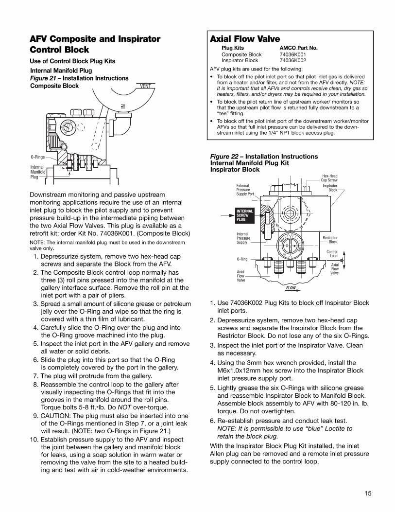
AFV Composite and InspiratorControl Block Use of Control Block Plug KitsInternal Manifold PlugFigure 21 �– Installation InstructionsComposite Block
Downstream monitoring and passive upstream monitoring applications require the use of an internalinlet plug to block the pilot supply and to prevent pressure build-up in the intermediate pipiing betweenthe two Axial Flow Valves. This plug is available as aretrofit kit; order Kit No. 74036K001. (Composite Block)NOTE: The internal manifold plug must be used in the downstreamvalve only.1. Depressurize system, remove two hex-head cap
screws and separate the Block from the AFV.2. The Composite Block control loop normally has
three (3) roll pins pressed into the manifold at thegallery interface surface. Remove the roll pin at theinlet port with a pair of pliers.
3. Spread a small amount of silicone grease or petroleumjelly over the O-Ring and wipe so that the ring iscovered with a thin film of lubricant.
4. Carefully slide the O-Ring over the plug and intothe O-Ring groove machined into the plug.
5. Inspect the inlet port in the AFV gallery and removeall water or solid debris.
6. Slide the plug into this port so that the O-Ring is completely covered by the port in the gallery.
7. The plug will protrude from the gallery.8. Reassemble the control loop to the gallery after
visually inspecting the O-Rings that fit into thegrooves in the manifold around the roll pins. Torque bolts 5-8 ft.*lb. Do NOT over-torque.
9. CAUTION: The plug must also be inserted into oneof the O-Rings mentioned in Step 7, or a joint leakwill result. (NOTE: two O-Rings in Figure 21.)
10. Establish pressure supply to the AFV and inspectthe joint between the gallery and manifold block for leaks, using a soap solution in warm water orremoving the valve from the site to a heated build-ing and test with air in cold-weather environments.
IN
MAX
MIN
InternalManifoldPlug
VENT
O-Rings
Axial Flow Valve Plug Kits AMCO Part No.Composite Block 74036K001Inspirator Block 74036K002
AFV plug kits are used for the following:
�• To block off the pilot inlet port so that pilot inlet gas is deliveredfrom a heater and/or filter, and not from the AFV directly. NOTE: It is important that all AFVs and controls receive clean, dry gas soheaters, filters, and/or dryers may be required in your installation.
�• To block the pilot return line of upstream worker/ monitors so that the upstream pilot flow is returned fully downstream to a�“tee�” fitting.
�• To block off the pilot inlet port of the downstream worker/monitorAFVs so that full inlet pressure can be delivered to the down-stream inlet using the 1/4" NPT block access plug.
ExternalPressureSupply Port
INTERNALSCREW PLUG
InternalPressureSupply
O-Ring
AxialFlowValve
AxialFlowValve
ControlLoop
RestrictorBlock
InspiratorBlock
Hex-HeadCap Screw
FLOW
Figure 22 �– Installation InstructionsInternal Manifold Plug KitInspirator Block
1. Use 74036K002 Plug Kits to block off Inspirator Blockinlet ports.
2. Depressurize system, remove two hex-head capscrews and separate the Inspirator Block from theRestrictor Block. Do not lose any of the six O-Rings.
3. Inspect the inlet port of the Inspirator Valve. Cleanas necessary.
4. Using the 3mm hex wrench provided, install theM6x1.0x12mm hex screw into the Inspirator Blockinlet pressure supply port.
5. Lightly grease the six O-Rings with silicone greaseand reassemble Inspirator Block to Manifold Block.Assemble block assembly to AFV with 80-120 in. lb.torque. Do not overtighten.
6. Re-establish pressure and conduct leak test.NOTE: It is permissible to use �“blue�” Loctite to retain the block plug.
With the Inspirator Block Plug Kit installed, the inletAllen plug can be removed and a remote inlet pressuresupply connected to the control loop.

16
Block Valve
Pilot With Secondary Diaphragm 60 Series Pilot
Pilot
Static
Inspirator
Axial Flow ValveBlock Valve
Sensitivity Control
Block Valve
Pilot W/O Secondary Diaphragm 1203
Inspirator
Axial Flow ValveBlock Valve
Sensitivity ControlPlug
Pilot
Inspirator Control ManifoldIntroductionThe following instructions cover the installation of the Inspirator Control Manifold (Figure 22) in both new and retrofit applications. The Inspirator Control
Manifold is an optional block intended for low differential-pressure service;
it replaces the standard control manifold block.
Retrofit InstallationsBegin installation by closing block valves up and downstream of the existing Axial Flow Valveand sense lines. Bleed the valve pressure to zero.
Disconnect the bleed and sense lines from the pilot.Remove the two bolts holding the existing manifold to the valve body. Lift off the manifold and pilot.Disconnect the pilot from the manifold.
Bolt the new Inspirator Control Manifold to the AxialFlow Valve using the bolts supplied so that the flowdirection arrow is pointed in the right direction.
New InstallationsFor new installations, follow the Inspirator ControlManifold assembly instructions above.
Refer to the schematic diagrams for installation ofsense and bleed lines in single valve (Figure 23), work-er/monitor (Figure 24), and relief/back pressure applica-tions (Figure 25).
IMPORTANT NOTE – In worker/monitor installations where the worker is downstream of the monitor and worker inlet pressure sense line is connected upstream of the monitor (Figure 24), amodification to the worker control manifold is necessary. The inlet pressure sense line is connected to the left side of the manifold block and a plug, Part Number 74036K002, is inserted in the inlet
pressure supply port. Refer to Figure 26 and its instructions forinstallation of the worker manifold plug.
AFV with Inspirator ControlInitial Setup, Single-Stage Pressure Reduction (PR)Figure 23Single-ValvePressure Applicationwith Inspirator
1. Set the Inspirator sensitivity control to maximumsetting No. 8*.
2. Relax pressure spring of pilot regulator by backingout adjustment screwuntil spring tension is at aminimum.
3. Crack downstream block valve.4. Crack upstream block valve to pressure Axial Flow
Valve.5. Fully open upstream and downstream block valves.6. Slowly increase pilot-pressure spring tension until
some downstream flow is achieved.7. Slowly increase pilot pressure spring tension until
downstream pressure approximates desired setpressure.
8. Tune system by alternately adjusting the pilot pres-sure spring and the sensitivity control until the setpoint and stable control are achieved at the high-est possible sensitivity setting under normal flowconditions.
9. Close downstream block valve to check for AFVlockup.
10. Gradually open downstream block valve.
* The Inspirator sensitivity control adjusts the rate of valve openingand closing. High sensitivity settings cause the valve to open andclose faster while lower settings reduce the response. A restrictorsetting of 5-6 is normal under most conditions.
Pilot DownstreamBleed or Exhaust
Inspirator Nozzle
PilotSupplyPressure
InspiratorFilter

17
AFV with Inspirator ControlInitial Setup, Worker/Monitor Pressure Reduction (PR)(Figure 24)
Setting the Worker1. Set the Inspirator sensitivity control of both worker
and monitor to maximum setting No. 8*.2. Relax the pressure spring of worker pilot by backing
out the adjustment screw until spring tension is ata minimum.
3. Increase pressure spring tension of monitor tomaximum of pressure spring range by turningadjusting screw inward.
4. Crack downstream block valve.5. Crack upstream block valve to pressure Axial Flow
Valve.6. Fully open upstream and downstream block valves.
7. Slowly increase pilot pressure spring tension ofworker until some flow is achieved.
8. Slowly increase worker pilot pressure spring tensionuntil downstream pressure approximates desiredset pressure.
9. Tune AFV worker by alternately adjusting the pilotpressure spring and the sensitivity control untilboth the required set point and stable control areachieved at the highest possible sensitivity settingunder normal flow conditions.
Setting the Monitor1. Slowly decrease monitor pilot pressure spring tension
until it begins to assume control from the worker.2. Fail worker wide open by disconnecting sense line
or increasing set point above desired monitor setpressure.
3. Tune monitor by adjusting pilot-pressure spring andsensitivity control until both the required set pointand stable control are achieved at the highest possible sensitivity control setting under normalflow conditions.
4. Place worker in operation by reversing action ofStep 2 above.
5. Close downstream block valve to check for AFVlockup.
6. Gradually open downstream block valve.* The Inspirator sensitivity control adjusts the rate of valve openingand closing. High sensitivity settings cause the valve to open faster while lower settings reduce the response time. A restrictor setting of 5-6 is normal under most conditions.
Block Valve
Static
Inspirator
Block Valve
Pilot
SensitivityControl
Axial Flow Valve with 60 Series RV Pilot
Block Valve
PilotMonitorStatic
Inspirator
Block Valve
SensitivityControl
Plug Plug
Pilot
WorkerStatic
SensitivityControl
Monitor AFV Worker AFV
Initial Setup, Back Pressure and Relief (RV) (Figure 25)1. Set Inspirator sensitivity control to maximum
setting 8*.2. Increase pressure spring tension of pilot by turning
adjusting screw inward until maximum tension isattained.
3. Open downstream block valve if used.4. Gradually introduce inlet pressure to the AFV.5. Gradually decrease pilot pressure spring tension until:
Back Pressure – some downstream flow isachievedRelief Valve – the desired set point is reached.
6. Back Pressure only – slowly decrease pilot pressurespring tension until upstream pressure approxi-mates desired set pressure. Tune system by alter-nately adjusting the pilot pressure spring and thesensitivity control until both the required set pointand stable control are achieved at the highest pos-sible under normal flow conditions.
* The Inspirator sensitivity control adjusts the rate of valve openingand closing. High sensitivity settings cause the valve to open faster while lower settings reduce the response time. A restrictor setting of 5-6 is normal under most conditions.

18
supplied, lubricate the O-ring and screw the hex-headplug with filter back into the manifold port until tight.
Inspirator Worker Manifold Plug Installation (Figure 26)NOTE: System must be depressurized before servicing.
1. Remove the Inspirator Composite Manifold BlockAssembly from the Axial Flow Valve by removing thehex head cap and screws.
2. Separate the Inspirator Block Assembly from theRestrictor Block. (Be sure not to lose the O-rings).
3. Inspect the inlet port in both blocks and remove anymoisture or debris.
4. Install internal screw plug (set screw, cone point, MG X 1.0 X 6g. 12 mm long) into internal pressuresupply port of the Inspirator Block.
5. Reassemble the Inspirator and Restrictor Blocks,making sure the three (3) O-rings between RestrictorBlock and Inspirator Block are in place.
6. Reassemble the Inspirator Composite ManifoldBlock Assembly to the Axial Flow Valve, making surethe three (3) O-rings are properly seated betweenthe AFV and the Manifold Block Assembly. Torquebolts to 5-8 ft.*lb. Do NOT over-torque.
7. Establish pressure supply to the AFV and be sure to inspect the joints between the AFV and RestrictorBlock and between the Restrictor Block andInspirator Block for leaks using a soap solution.
AFV with Inspirator andComposite ControlsManifold Inspection and MaintenanceInspirator Core (Venturi)The restrictor core should be inspected at all normalservice periods, or when the control pressure beginsto deteriorate, for dirt build up on the restrictor grooveand wear of the two O-rings. To remove the restrictor core from either the inspiratoror composite manifold, depressurize the valve, removethe retaining ring holding the core in place and slidethe core out from the manifold. Inspect the restrictor core and clean any debris thatmay have collected in the restrictor groove. Inspectboth O-rings for any sign of wear, replace if necessaryand always lubricate the O-rings with silicone grease or oil before reinstalling the restrictor core. On the completion, slide the restrictor core back inplace, reattach the retaining ring to the restrictor coreand adjust restrictor to the previous setting.
Composite Manifold FilterThe composite manifold filter element should beinspected at all normal service periods or when setcontrol pressure begins to deteriorate. To remove the filter for inspection or replacement,depressurize and unscrew the large hex-head plug with O-ring on top of the manifold.Remove the spring, washer and gasket in this order.Remove the filter and replace with a new filter element,Part Number 78480P001, making sure the closed endof the filter element goes in first. Reverse the removalsteps above for replacement making sure the hex-headO-ring is lubricated.
Inspirator Manifold FilterThe inspirator manifold filter should be inspected at allnormal service periods or when set control pressurebegins to deteriorate.To remove the filter for inspection or replacement,depressurize the valve and unscrew the large hex-headplug on the side of the manifold. The filter utilizes a compression fit inside of the hexhead plug. Simply remove the old filter element andreplace with the new element (Part Number 74074K001)making sure a secure fit is achieved. Next, replace the hex head O-ring with the new O-ring
Allen Plug ExternalPressureSupply Port
INTERNALSCREW PLUG Part Number 74036K002
InternalPressureSupply (blocked by plug)
O-Ring
AxialFlowValve
AxialFlowValve
ControlLoop
RestrictorBlock
InspiratorBlock
Hex-HeadCap Screw
FLOW
Figure 26Inspirator Blockwith Plug Kit

19
Axial Flow Valves – Maintenance
Figure 27 – Axial Flow Valve Components (typical)
Sleeve Grooves
*Rubber Sleeve
Sleeve Ribs forControl PressureDistribution
Downstream Roll Pin
O-RingCage ClosureTab
Fairing Nut
Fairing NutO-Ring
* Downstream Cage Closure
Downstream Rib
Downstream Control PressureDistribution GrooveValve Body
Gallery
CenterBarrier
Cage
UpstreamRoll Pin
O-RingClosure Passage
Fairing Nut
O-Ring
Rubber Sleeve
Body
Valve CageClosure
Washer
Bolt
O-Ring
Roll Pin
Center Bolt
Washer
* Upstream CageClosusre
Cage Closure Notch
FLOW DIRECTION
* Cage closures are interchangeable. Rubber sleeve can be installed in either direction.The Axial Flow Valve is capable of bi-directional flow control.
CAUTION:“As a knowledgeable user of American Meter Company products, you should be aware that parts inthe Company’s meters and regulators contain or are coated with heavy metals such as cadmium, zinc,lead and chromate. Obviously, therefore, repair and refurbishment of this equipment should take intoaccount the presence of these materials and should comply with all state and federal requirementsconcerning worker protection, proper repair procedure and proper disposal.”
WARNING – EXPLOSION HAZARDRead carefully and follow all instructions shipped with this regulator. The incorrect specification or installation of this equipment could result in escaping gas and pose a potential explosion hazard.Refer to AMCO documents SB 9509, IMP 9710 and TDB 9610 (Axial Flow Valves) and SB 9800, PL 9810, SB 8545 and RPL 8845 for technical information, including recommended installation guidelines.
FLOW DIRECTION

20
Figure 28
Figure 29
Figure 30
Figure 31
Axial Flow ValvesDisassemblyUnder normal operating conditions, the Axial FlowValve is capable of long service. The service life can be markedly increased by timely inspections and byreversing the upstream and downstream ends of therubber sleeve.
1. Clean exterior of Valve.
2. To remove the single center bolt, it is necessary tostop the fairing nut from turning by use of a wrenchon the nut flats. Loosen the center bolt by using asocket wrench on the hex head of the bolt. (Figure 28)NOTE: The fairing nut has been provided with flat wrench surfacesfor holding the nut. Some models have a slotted fairing nut whichrequires the use of a screwdriver. Do not turn the fairing nut toloosen the center bolt. This could result in O-ring damage.
3. Remove bolt and washer, fairing nut and O-ring.(Figure 29)
4. Insert screwdriver in the cage closure notch(Figure 30) and turn to loosen cage from body.Continue to raise cage closure with screwdriveruntil the screwdriver can be inserted near thegallery. Pry the cage closure from the roll pin in thegallery. The cage closure can now be removed. Takecare not to damage the machined faces of the bodyor cage closure.
5. Carefully remove O-ring from roll pin. (Figure 31)
6. Repeat Step 4 and remove the other cage closure.Keep downstream cage closure to the right for purpose of identification.
7. Carefully remove O-ring from roll pin.
8. Mark downstream edge of a sleeve with chalk or soft pencil.
9. Loosen sleeve from both ends of body by pullingsleeve toward center and breaking seal. (If prying is necessary, use a smooth rounded instrument).(Figure 32)
10. Using your hand, force a section of the sleevetoward the opposite side. (Figure 33)
11. Grasp the fold in the sleeve, make sure the sleeveis free of both annular ribs in the body, and liftsleeve from body. (Figure 34)
Refer to important handling information on page 1.
Figure 34
Figure 33
Figure 32

21
Axial Flow ValvesInspection1. Inspect upstream and downstream cage closure
roll pins. Replace if damaged.
2. Inspect interior of valve body for unusual marks or corrosion. Clean thoroughly. Blow out gallerypassages (Figure 35). The central control pressurepassage has two interior ports. Be certain both haveno blockage.
3. Inspect exterior of body for damage. Inspect weldbetween body and gallery.
4. Clean cage closure (Figure 36). Inspect for erosionand keep track of downstream cage closure byplacing it to the right. Discard cage closure thatshows noticeable erosion or has reduced the thick-ness or width of the cage ribs. (A slight rounding ofthe edges of the ribs will not affect the valve.)
5. Inspect sleeve before cleaning. Note any unusualmarks and imprints. Check the sleeve for swelling orany noticeable change in hardness (flexibility).
6. Clean the sleeve carefully, checking the areas whereunusual marks or imprints were observed. Look forwear and breaks in sleeve surface.
7. Discard and replace with new sleeve if any defectsother than normal wear are observed.
8. Inspect bolt, washer, and fairing nut for pits and corrosion.
9. It is usually good practice to replace O-rings. Ifthere is no distortion, nicks, excessive swelling orhardening, it is possible to reuse the O-rings.
Axial Flow ValvesReassembly1. Use the former downstream cage in the upstream
side. Turn the sleeve so that the former down-stream side faces upstream. Using spray-type silicone lubricant, lightly lubricate the sleevegrooves and opposing internal surfaces. Lightly lubricate the two gallery O-rings.
2. Push the section of the sleeve toward the oppositeside and grasp the fold. (Figure 37)
3. Insert the folded sleeve in the body and engage thesleeve grooves on the internal annular ribs—bothupstream and downstream. (Figure 38)
4. Gradually seat the sleeve groove on the ribs andrelease the fold. Press until the seating is completeon both ribs.
5. (Replace damaged roll pins). Gently press galleryO-rings around both upstream and downstream roll pins.
6. Place former downstream cage closure overupstream side of body so that the passage in theclosure tab engages the roll pin. This aligns thecage closure.
7. Press the cage closure down as far as possible(Figure 39) Check for proper alignment of passageand roll pin. Continued on page 22.
Figure 35Axial Flow Valve Body
Figure 37
Figure 38
Figure 39
Supply Control Pressure Passage
Branched Control Pressure Passage
DownstreamBleed Passage
Control PressureGroovesValve
BodyRibs
Valve Body Cross SectionThrough Gallery
Figure 36 Axial Flow ValveClosure
Plug CageClosureEar
CageClosurePassage
Cage
CenterBarrier

22
Axial Flow ValveStorageThe Axial Flow Valve is ruggedly constructed from corrosion-resistant steel. The rubber products used inthe standard valves are durable and resistant to aging.Valves can be stored in conditions commonly found inmost warehouses and tool rooms. A clean, cool, dryarea is ideal for storage.
New Valves can be stored in shipping containers.
Valve Storage – Ideally, Axial Flow Valves should bestored in original shipping containers. Plastic bags mayalso be used and will prevent foreign material andinsects from entering valve passages. When removingan Axial Flow Valve from service, it is recommendedthe valve be thoroughly cleaned and inspected prior to being stored.
Sleeve Storage – Sleeves should be kept out of directsunlight and away from contaminants, radiation andozone-producing electrical equipment. Temperaturesabove 100°F are to be avoided.
Axial Flow ValvesReassembly Continued
8. Install downstream cage closure. Steps 6 and 7.
9. Place washer under head of center bolt, apply anti-seize compound to threads. Push bolt with washerthrough upstream cage to extend through down-stream cage closure.
10. Do not lubricate fairing nut O-ring. This will facilitatetorquing center bolt without need of holding the nut.Insert fairing nut O-ring into groove of fairing nut.
11. Thread fairing nut onto bolt until finger tight.
12. Torque center bolt to the following torques:
300 and 600 Series
Valve Size Torque
2" and 3" 20 to 30 ft. lbs.
4" 40 to 60 ft. lbs.
6" 75 to 100 ft. lbs.
8" 140 to 180 ft. lbs.
12" 375 to 475 ft. lbs.
Note: The fairing nut is provided with flat wrench sur-faces for holding the nut. This should not be necessaryif the fairing nut O-ring is dry.
Do not torque the center bolt by turning the fairing nut.
Axial Flow Valve sleeves should be stored in their polyethylene bags inside a box or in polyethylene-linedpaper bags.
It may not be practical to keep certain rubber parts incontainers due to the possibility of shape deformation.Sleeves should be stored in such a way as to minimizethe effects of the above noted contaminants.
Approximate shelf life for Axial Flow Valve Sleeves:Sleeve Type YearsBuna N and HNBR 2Natural Rubber 2Hydrin 5Viton 10Fluorosilicone 10
Sleeve Data Stamp (Figure 40)All Axial Flow Valve sleeves utilize a manufacturer’sdate stamp found below the sleeves’ ID code next to the color code.
Because each sleeve has a specific shelf life, the datastamp will be useful in determining the proper time touse the sleeve.
Figure 40 below illustrates the stamp showing thenumeric digit in the center of the circle representing the latest manufactured year by utilizing the last digit of that specific year.
The punch marks in the outer circle represent each calendar month for the year moving clockwise from the 12 o’clock position.
Punch Mark Added ToMold For Each CalendarMonth C.W. From 12:00
Last Digit Of YearOf Manufacturer(1/8˝ Height Min.)
Date Code(E.G. Oct. 01)
AFV Sleeve
1/8˝
12:00
Figure 40Sleeve Data Stamp

23
Axial Flow Valves – Repair Parts and AccessoriesStud Bolts and Nuts – 300 Series
Valve ANSI Diameter No. of Threads Length Stud Bolt No. Nut No.Size Flange (inches) per inch (inches) Part No.�† Required Part No. Required
2, 2R 125-150 5/8 11 UNC 7 78018P029 4 78019P033 8250-300 5/8 11 UNC 7-1/4 78018P030 8 78019P033 16
3 125-150 5/8 11 UNC 8 78018P031 4 78019P033 8250-300 3/4 10 UNC 8-1/2 78018P032 8 78019P036 16
4 125-150 5/8 11 UNC 8-3/4 78018P033 8 78019P033 16250-300 3/4 10 UNC 9-3/4 78018P034 8 78019P036 16
6 125-150 3/4 10 UNC 10-1/4 78018P035 8 78019P036 16250-300 3/4 10 UNC 11 78018P036 12 78019P036 24
8 125-150 3/4 10 UNC 11-1/2 78018P037 8 78019P036 16250-300 7/8 9 UNC 12-3/4 78018P038 12 78019P039 24
12 125-150 7/8 9 UNC 14-3/4 78018P041 12 78019P039 24250-300 1-1/8 8 UNC 16-3/4 78018P042 16 78019P045 32
Stud Bolts and Nuts – 600 Series2, 2R 600 5/8 11 UNC 8-1/4 78018P050 8 78019P033 16
4 600 7/8 9 UNC 11-3/4 78018P052 8 78019P039 166 600 1 8 UNC 14-1/4 78018P053 12 78019P041 248 600 1-1/8 8 UNC 16-1/2 78018P054 12 78019P045 24
�† Continuous threadsMaterial �– ASTM Specification A 307 Grade B �– Plating Zinc per AMD T-1015
Axial Flow Valve Sizes and Weights
Valve Size (inches) Weight (lbs) Width (inches)
300 Series2, 2R 5-3/4 3-1/32
3 9 3-23/324 19 4-1/26 38 5-1/28 80 6-23/3212 177 9-7/16
600 Series2 7-1/2 3-13/324 31-1/2 5-1/46 73-1/2 6-7/88 122 8-5/64
For additional literature and product information, please refer to thefollowing bulletins:
SB 8545 Z Pilot Regulators
RPL 8845 Z Pilot Regulators
SB 9509 Axial Flow Valves
SB 9510 Axial Flow Valves
TDB 9610 AFV Capacity Tables
SB 9800 60 Series Pilot Regulators
PL 9810 60 Series Pilot Regulators
Optional Accessory – 300 Series Centering Tubes
Description Valve Size (in.) Quantity Part No.
Centering 2, 2R 2 73552P001Tubes 3 2 73552P002
4 2 73552P0036 2 73552P0048 2 73552P00512 2 73552P007
300 and 600 Series AccessoriesFlange Separator* 2, 2R, 3, 4 2 73593G001(300 Series Only) 6,8 2 73593G002
12 2 73593G003
Lifting Plate ** 2 thru 12 1 73672P001
1203 Pressure 2 thru 12 1 74073K001Adjusting Screw Retrofit Kit
New or Replacement 2 thru 12 1 74067K001Inspirator Block Assy.Complete w/Plug
New or Replacement 2 thru 12 1 73957G014Composite Block Assy.Complete Pressure- 73957W014Tested Assy.
New or Replacement 2 thru 12 1 73573W004Bare AFV Block.No Adjuster �– NPT Tapped
Internal Composite 2 thru 12 1 74036K001Manifold Plug
Inspirator Control 1 74036K002Manifold Plug
* Flange Separators – The installation and removal of the valve may be facilitated by the use oftwo flange separators. Flange separators are placed on each side of the valve to jack the flangesapart and thereby relieve a piping strain to facilitate valve removal and replacement.
** Lifting Plate – Provides a 1" x 1-1/2" aperture for engagement by hook, chain, or cable for lifting the Axial Flow Valve. The lifting plate is particularly useful for handling the 8-inch and 12-inch valve. The lifting plate attaches to the valve gallery utilizing the same two 5/16" x 2" boltsrequired for the manifold block.

24
ValveSize Qty. Part Number
Closure, Valve Cage, 17-4 Stainless Steel2 2 73402P0013 2 73402P0024 2 73402P0036 2 73402P0048 2 73402P005
12 2 73402P007
Reduced-Capacity Valve Cage2R10 1 73402P0162R25 1 73402P0152R50 2 73402P008
Sleeve, Buna N �– Durometer 50, Low Delta Pressure Code B5-LOrange Stripe
2, 2R 1 73404P0673 1 73404P0684 1 73404P0696 1 73404P0708 1 73404P07212 1 73404P074
Sleeve, Buna N �– Durometer 50, Code B7, Blue Stripe2, 2R 1 73404P055
3 1 73404P0574 1 73404P0596 1 73404P0618 1 73404P06312 1 73404P065
Sleeve, Buna N �– Durometer 70, Code B7, Blue Stripe2, 2R 1 73404P056
3 1 73404P0584 1 73404P0606 1 73404P0628 1 73404P06312 1 73404P066
Sleeve, Hydrin 200�† - Durometer 50, Low Delta Pressure CodeH-5L, Orange Stripe
2, 2R 1 73404P0513 1 73404P0524 1 73404P0536 1 73404P0548 1 73404P07112 1 73404P073
Sleeve, Hydrin 200�† - Durometer 50, Code H5, Blue Stripe2, 2R 1 73404P008
3 1 73404P0094 1 73404P0106 1 73404P0118 1 73404P01212 1 73404P014
Sleeve, Hydrin 200�† - Durometer 70, Code H7, Blue Stripe2, 2R 1 73404P002
3 1 73404P0034 1 73404P0016 1 73404P0048 1 73404P00512 1 73404P007
Sleeve, Viton �– Durometer 70, Code V7, Blue Stripe2, 2R 1 73404P015
3 1 73404P0164 1 73404P0176 1 73404P018
�† Trademark B F Goodrich Co.
Axial Flow Valve – Repair Parts150/300 Series (Figure 41)
ValveSize Qty. Part Number
Sleeve, Fluorosilicone Rubber, Durometer 50, Code F5, Blue Stripe2, 2R 1 73404P033
3 1 73404P0344 1 73404P0356 1 73404P036
Sleeve, Natural Rubber, Durometer 70, Code N7, Blue Stripe2, 2R 1 73404P039
3 1 73404P0404 1 73404P0416 1 73404P0428 1 73404P04312 1 73404P044
Sleeve, HNBR, Durometer 65, Code HB(Maximum toughness for Buna applications)
2, 2R 1 73404P0763 1 73404P0774 1 73404P0786 1 73404P0798 1 73404P08012 1 73404P081
Fairing Nut, Stainless Steel2, 2R 1 73401P001
3 1 73401P0014 1 73401P0026 1 73401P0038 1 73401P00412 1 73401P005
Screw Cap, Stainless Steel2, 2R 1 78000P090
3 1 78000P0934 1 78000P0876 1 78000P0948 1 78000P09512 1 78000P091
Washer, Stainless Steel2, 2R 1 70176P041
3 1 70176P0414 1 70176P0396 1 78034P0138 1 70176P04312 1 78034P012
O-Ring, (Fairing Nut) Buna N (standard)2, 2R 1 42710P150
3 1 42710P1504 1 42710P0816 1 42710P1558 1 42710P15612 1 42710P160
O-Ring, Fairing Nut, Viton A2, 2R 1 78037P096
3 1 78037P0964 1 78037P0976 1 78037P098
O-Ring, Roll Pin, Buna A (Standard)All 2 42710P146
O-Ring, Roll Pin, Viton AAll 2 78037P094
Roll Pin 1/4"D x 3/8"L Steel (Standard)2, 2R 2 78137P004
3, 4, 6, 8, 12 2 78137P003
Roll Pin 1/4"D x 1/2"L Stainless Steel2, 2R 2 N/A
3,4,6,8,12 2 78137P005
2
2A
3
3
3
3
3
3
3
3
3
3
4
5
6
7
7
8
8
9
9

ValveSize Qty. Part Number
Closure, Valve Cage, 17-4 Stainless Steel2 2 73679P0014 2 73679P0036 2 73679P0048 2 73679P005
Reduced Capacity Valve Cage2R10 1 73679P0092R25 1 73679P0082R50 2 73679P007
Sleeve, Buna N (Std.) Durometer 70, Code B7, Red Stripe2, 2R 1 73677P007
4 1 73677P0086 1 73677P0098 1 73677P010
Sleeve, Viton Durometer 70, Code V7, Red Stripe2, 2R 1 73677P011
4 1 73677P0126 1 73677P0138 1 73677P014
Sleeve, Hydrin Durometer 70, Code H7, Red Stripe2, 2R 1 73677P001
4 1 73677P0036 1 73677P0048 1 73677P005
Sleeve, HNBR, Durometer 65, Code HB, Red Stripe(Maximum toughness for Buna applications)
2, 2R 1 73677P0154 1 73677P0166 1 73677P0178 1 73677P018
Axial Flow Valve – Repair Parts600 Series – High Pressure (Figure 41)
ValveSize Qty. Part Number
Nut, Fairing, Stainless Steel (Center Bolt)2, 2R 1 73401P001
4 1 73401P0026 1 73401P0038 1 73401P004
Screw Cap, Stainless Steel2, 2R 1 78000P090
4 1 78000P0876 1 78000P0948 1 78000P095
Washer, Stainless Steel2, 2R 1 70176P041
4 1 70176P0396 1 78034P0138 1 70176P043
O-Ring, Fairing Nut, Buna N2, 2R 1 42710P150
4 1 42710P0806 1 42710P1558 1 42710P156
O-Ring, Roll Pin, Buna NAll 2 78037P003
Roll Pin, 1/4"D x 3/8"L, 1/4"D x 1/2"L2, 2R 2 78137P004
4 2 78137P0036 2 78137P0038 2 78137P0036 2 78137P0058 2 78137P00512 2 78137P005
2
6
7
8
9
2A
3
3
3
3
4
5
Figure 412A. Reduced
Capacity Cages(2" only)
3. Sleeve
8. O-Ring, Roll Pin
9. Roll Pin9. Roll Pin
2. Closure, Valve Cage2. Closure, Valve Cage
7. O-Ring, Fairing Nut
4. Nut, Fairing
1. Body
8. O-Ring, Roll Pin
6. Washer
5. Screw Cap
25

American Meter Company has a program of continuous product development and improvement; and, therefore, the information in this bulletin is subject to change or modification without notice.
©2005 American Meter Company 9/05 5M Core Printed in U.S.A.
Control Loop Assemblies Continued
Description Quantity Per Unit Part No.
16 Bushing, Reducing 1 78041P002(use with 17A only)
17A Model 1203 �– 180 �– Pilot 1 73958G017
17B Type 60 Series 1 See SB9800
18 Connector, Tube 1 78109P001
19 Sleeve 2 78109P004
20 Nut, Tube Connector 2 78109P003
21 Tubing �– 3/8" 1 72201P013
22 Elbow 1 78109P002
23 Valve, Axial Flow 1
24 Restrictor, Dampening 1 73688G002
25 Filter Assembly, 1 74074K001Inspirator Block (optional)
26 Inspirator Assembly 1 74067K001
27 Screw, Hex Head, Steel 2 78000P107
28 Washer, Flat, Steel 2 70176P040
29 Cap, 60 Series 1 55472P005
Control Loop Assemblies
Description Quantity Per Unit Part No.
1 Block, Manifold �– Assembly 1 73957G001(includes items #2 thru 13)
2 Plug, Hex Hd. W/O-Ring 1 78479P001
3 Spring 1 71403P012
4 Washer 1 78034P016
5 Gasket 1 70019P106
6 Filter Assembly 1 78480P001
7 Screw, Hex Head, Steel 2 78999P106Stainless Steel 2 12369P041
8 Washer, Steel 2 70176P040Stainless Steel 2 70176P045
9 Ring, Retaining 1 78074P029
10 Core, Restrictor 1 73659P003
11 O-Ring 5 78037P003
12 Roll Pin 3 78137P003
13 Plug, Pipe 1/4" W/17A pilot, Steel 3 78039P003
Stainless Steel 3 11970P025W/18B pilot, Steel 2 78039P003
Stainless Steel 2 11970P025
14 Nipple, Pipe �– 1/4" 2 78044P006
15 Elbow 1 78041P002
AMERICAN METER
132 Welsh Road, Suite 140Horsham, PA 19044 U.S.A.Phone: 215/830-1800Fax: 215/830-1890Website: americanmeter.com
275 Industrial RoadCambridge, Ontario N3H 4R7 CanadaPhone: 877/461-2626 (toll free)Phone: 519/650-1900Fax: 519/650-1917Website: canadianmeter.com
CANADIAN METER
25
29
2728
26
2
3
456
78
1011
1112
23
913
18
14
15
24
1617A
17B
ILF00100
1
2219
20
Figure 42