(autonomous) (iso/iec - 27001 - 2005 certified) …msbte.engg-info.website/sites/default/files/temp...
TRANSCRIPT
MAHARASHTRA STATE BOARD OF TECHNICAL EDUCATION (Autonomous)
(ISO/IEC - 27001 - 2005 Certified)
____________________________________________________________________________________________
SUMMER– 14 EXAMINATION Subject Code: 17412 Model Answer
Page 1 of 28
Important Instructions to examiners:
1) The answers should be examined by key words and not as word-to-word as given in the
model answer scheme.
2) The model answer and the answer written by candidate may vary but the examiner may try
to assess the understanding level of the candidate.
3) The language errors such as grammatical, spelling errors should not be given more
Importance (Not applicable for subject English and Communication Skills.
4) While assessing figures, examiner may give credit for principal components indicated in the
figure. The figures drawn by candidate and model answer may vary. The examiner may give credit for
any
equivalent figure drawn.
5) Credits may be given step wise for numerical problems. In some cases, the assumed constant
values may vary and there may be some difference in the candidate’s answers and model answer.
6) In case of some questions credit may be given by judgement on part of examiner of relevant answer
based on candidate’s understanding. 7) For programming language papers, credit may be given to any other program based on equivalent
concept.
Que. No. 1 a) Attempt any SIX 12
i) List of various types of clutches used to transmit Power
(FOUR TYPES two marks, each type - half mark)
a) Single plate clutch b) Multi plate clutch c) Cone clutch d) Centrifugal clutch
ii) Classification of follower:
(Two marks, 1 + ½ + ½)
1. According to the surface in contact:
Knife-edge follower
Roller follower
Flat faced or mushroom follower
Spherical follower
2. According to the motion of the follower:
Reciprocating or translating follower
Oscillating or rotating follower
3. According to the path of motion of follower:
MAHARASHTRA STATE BOARD OF TECHNICAL EDUCATION (Autonomous)
(ISO/IEC - 27001 - 2005 Certified)
____________________________________________________________________________________________
SUMMER– 14 EXAMINATION Subject Code: 17412 Model Answer
Page 2 of 28
Radial follower
Off-set follower
iii) (Two marks, 1 + 1)
Advantages of chain drive: (any two)
1. As no slip takes place, hence, perfect velocity ratio is obtained (Positive drive).
2. Chain drive gives high transmission efficiency (up to 98 %).
3. Chain drive may be used when the distance between the shafts is less.
4. Chain is made up of metal which would occupy less space as compared with belt or rope
drive.
5. Ability to transmit power to several shafts by one chain.
6. Load on the shaft is less and long life.
Disadvantages of chain drive: (any two)
1. Manufacturing cost of chains is relatively high
2. The chain drive needs accurate mounting and careful maintenance
3. High velocity fluctuations especially when unduly stretched
4. Chain operations are noisy as compared to belts
iv) (Any FOUR TYPES to be written. Two marks, each type - half mark)
List of various types bearings used
1. Flat pivot
2. Conical pivot
3. Truncated pivot
4. Single flat collar
5. Multiple flat collar
v) (Function to be written. Two marks)
The function of governor is to regulate the mean speed of the engine, when there are variations in
the load. Governor automatically adjusts and controls the supply of fuel / working fluid to the
engine with the varying load conditions and keeps the mean speed within the certain desired
limits.
e.g. When the load on an engine increases, its speed decreases, therefore it becomes necessary to
increase the supply of fuel or working fluid. The configuration of the governor changes and
valve is moved to increase the supply of working fluid. Conversely, when the load on the engine
MAHARASHTRA STATE BOARD OF TECHNICAL EDUCATION (Autonomous)
(ISO/IEC - 27001 - 2005 Certified)
____________________________________________________________________________________________
SUMMER– 14 EXAMINATION Subject Code: 17412 Model Answer
Page 3 of 28
decreases, its speed increases, and thus, less working fluid is required. Hence, the governor
decreases the supply of working fluid.
vi) (Definition of fluctuation of speed one mark, fluctuation of energy one mark)
Fluctuation of speed: It is the difference between the maximum and minimum speed of
Flywheel.
Fluctuation of speed = (N1 – N2) rpm N1 – maximum speed, N2 -- minimum speed
Fluctuation of energy: It is the difference between the maximum and minimum energy of
Flywheel.
Maximum energy of Flywheel I ω1
2
Minimum energy of Flywheel = I ω2
2
Fluctuation of energy =
I (ω1
2 - ω2
2) in N-m or J
I – moment of inertia of flywheel = mk2
where, m – mass of the flywheel, kg and k - radius of gyration of flywheel, m2
ω1 – Maximum Angular velocity, rad/sec
ω2 – Minimum Angular velocity, rad/sec
vii) (Any FOUR TYPES to be written. Two marks, each type - half mark)
Types of brakes:
Based on actuation or means of transforming energy:
1. Hydraulic brakes
2. Electric brakes
3. Mechanical brakes
4. Pneumatic brakes
Based on the direction of acting force:
Radial brakes
External a) shoe brake b) band brake c) band and block brake
MAHARASHTRA STATE BOARD OF TECHNICAL EDUCATION (Autonomous)
(ISO/IEC - 27001 - 2005 Certified)
____________________________________________________________________________________________
SUMMER– 14 EXAMINATION Subject Code: 17412 Model Answer
Page 4 of 28
Internal a) Internal expanding brake
Axial or disc brakes
viii) Balancing meaning one mark, methods one mark (any two methods)
The process of providing the second mass in order to counter act the effect of the centrifugal
force of the disturbing mass is called balancing. In order to prevent the bad effect of centrifugal
force of disturbing mass, another mass (balancing) is attached to the opposite side of the shaft at
such a position, so as to balance the effect of centrifugal force of disturbing mass. This is done in
such a way that the centrifugal forces of both the masses are made equal and opposite.
Methods of balancing:
Balancing of rotating masses
1) Balancing of a single rotating mass by a single rotating mass in the same plane
2) Balancing of a single rotating mass by two masses rotating in the different planes
* Disturbing mass lies in a plane between the planes of balancing masses
* Disturbing mass lies in a plane on one end of the planes of balancing masses
3) Balancing of different masses rotating in the same plane
4) Balancing of different masses rotating in the different planes
Balancing of reciprocating masses
Que. No. 1 b) Attempt any TWO
i) (Definition of Kinematic pair One mark, Types Three marks)
Kinematic pair:
When two kinematic links or elements are in contact with each other such that relative motion
between them is either completely constrained or successfully constrained.
Types:
Based on nature of relative motion
Sliding pair / Prismatic pair
Turning pair / Revolute pair
Screw pair / Helical pair
Spherical pair / Globular pair
Rolling pair
Based on nature of contact
MAHARASHTRA STATE BOARD OF TECHNICAL EDUCATION (Autonomous)
(ISO/IEC - 27001 - 2005 Certified)
____________________________________________________________________________________________
SUMMER– 14 EXAMINATION Subject Code: 17412 Model Answer
Page 5 of 28
Lower pair
Higher pair
Based on nature of closure
Self closed pair
Force- closed pair
ii) (Types of clutches: Two marks, applications Two marks)
Types of clutches:
a) Single plate clutch b) Multi plate clutch c) Cone clutch d) Centrifugal clutch
Applications:
a) Single plate clutch: Heavy vehicles, four-wheeler such as car, truck, bus
b) Multi plate clutch: Two wheelers, mopeds, scooters, bikes
c) Cone clutch: Machine tools, automobiles, press work
d) Centrifugal clutch: mopeds, Luna
iii) One application ONE mark
V- Belt drive – air compressor, machine tools (drilling machine)
Flat belt drive - lathe headstock, floor mill, stone crusher unit
Gear drive – gear box of vehicles, cement mixing unit, machine tools, I.C. Engine,
differential of automobile, dial indicator
Chain drive – Bicycle, cranes, Hoists, bikes
Que. No. 2 Attempt any FOUR 16
a) (Any Four points - four marks)
Sl.
No. Machine Structure
1 All parts / links have relative motion No relative motion between the links
2 It transforms the available energy into some
useful work
No energy transformations
MAHARASHTRA STATE BOARD OF TECHNICAL EDUCATION (Autonomous)
(ISO/IEC - 27001 - 2005 Certified)
____________________________________________________________________________________________
SUMMER– 14 EXAMINATION Subject Code: 17412 Model Answer
Page 6 of 28
3 The kinematic link of a machine may
transmit both power and motion
The member of the structure transmit
forces only
4 Examples: I.C. Engine, Machine tools,
steam engine, type writer, etc.
Example: Truss of roof, frame of
machine, truss of bridge
5 Studied under 'Dynamics' Studied under 'Statics'
b) (Sketch 2 marks, explanation 2 marks)
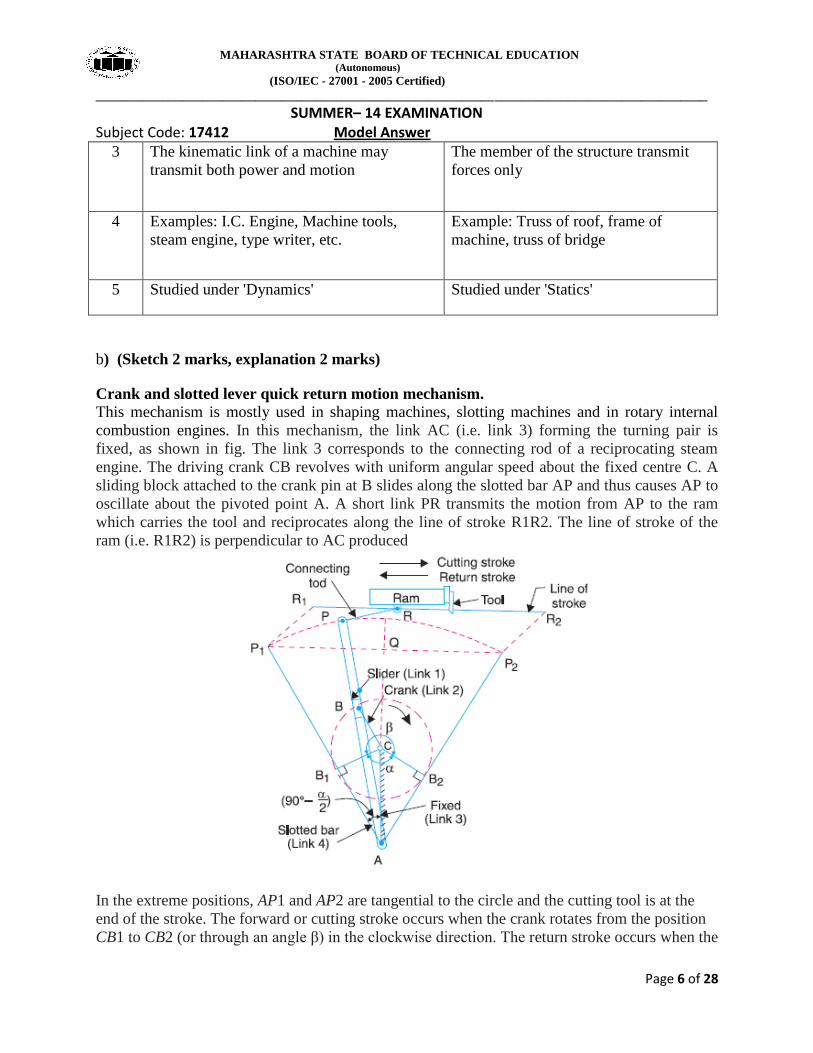
Crank and slotted lever quick return motion mechanism.
This mechanism is mostly used in shaping machines, slotting machines and in rotary internal
combustion engines. In this mechanism, the link AC (i.e. link 3) forming the turning pair is
fixed, as shown in fig. The link 3 corresponds to the connecting rod of a reciprocating steam
engine. The driving crank CB revolves with uniform angular speed about the fixed centre C. A
sliding block attached to the crank pin at B slides along the slotted bar AP and thus causes AP to
oscillate about the pivoted point A. A short link PR transmits the motion from AP to the ram
which carries the tool and reciprocates along the line of stroke R1R2. The line of stroke of the
ram (i.e. R1R2) is perpendicular to AC produced
In the extreme positions, AP1 and AP2 are tangential to the circle and the cutting tool is at the
end of the stroke. The forward or cutting stroke occurs when the crank rotates from the position
CB1 to CB2 (or through an angle β) in the clockwise direction. The return stroke occurs when the
MAHARASHTRA STATE BOARD OF TECHNICAL EDUCATION (Autonomous)
(ISO/IEC - 27001 - 2005 Certified)
____________________________________________________________________________________________
SUMMER– 14 EXAMINATION Subject Code: 17412 Model Answer
Page 7 of 28
crank rotates from the position CB2 to CB1 (or through angle α) in the clockwise direction. Since
the crank has uniform angular speed,
c) (one mark each for stating formulae for velocity and acceleration of piston & connecting
rod)
Velocity of piston, Vp = ω r ( +
)
State all the terms:
ω = angular velocity of the crank, rad/sec
n = Ratio of length of connecting rod to the radius of crank
= l / r (Obliquity of connecting rod)
θ = Angle made by the crank with Inner Dead Centre (IDC)
r = radius of crank, l = length of connecting rod
Acceleration of piston, Ap = ω2 r +
Angular velocity of connecting rod
MAHARASHTRA STATE BOARD OF TECHNICAL EDUCATION (Autonomous)
(ISO/IEC - 27001 - 2005 Certified)
____________________________________________________________________________________________
SUMMER– 14 EXAMINATION Subject Code: 17412 Model Answer
Page 8 of 28
Angular acceleration of connecting rod, αcr = - ω2
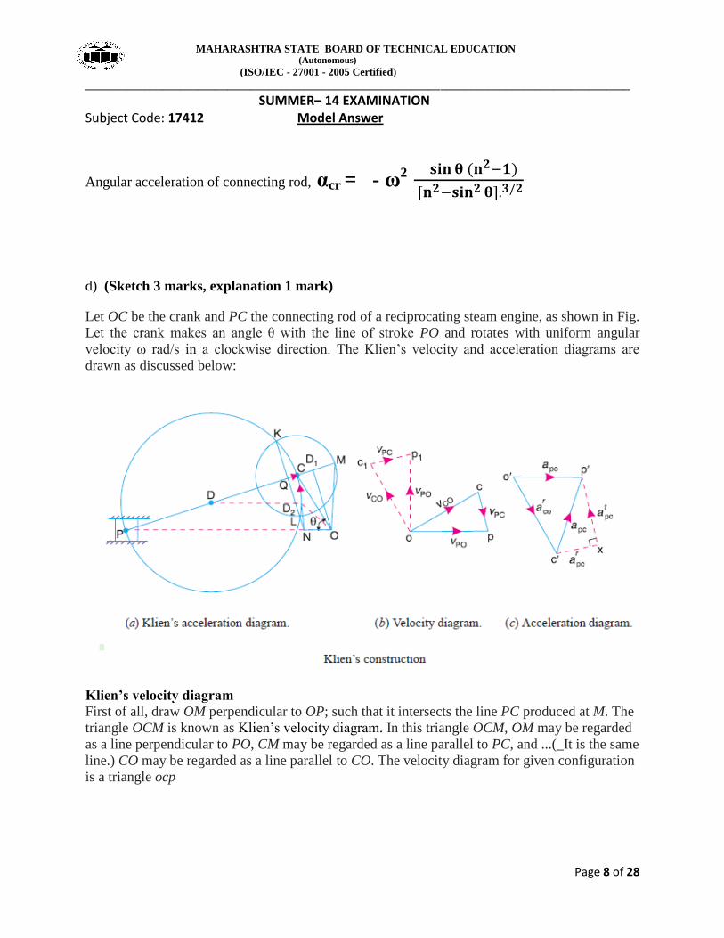
d) (Sketch 3 marks, explanation 1 mark)
Let OC be the crank and PC the connecting rod of a reciprocating steam engine, as shown in Fig.
Let the crank makes an angle θ with the line of stroke PO and rotates with uniform angular
velocity ω rad/s in a clockwise direction. The Klien’s velocity and acceleration diagrams are
drawn as discussed below:
Klien’s velocity diagram
First of all, draw OM perpendicular to OP; such that it intersects the line PC produced at M. The
triangle OCM is known as Klien’s velocity diagram. In this triangle OCM, OM may be regarded
as a line perpendicular to PO, CM may be regarded as a line parallel to PC, and ...(_It is the same
line.) CO may be regarded as a line parallel to CO. The velocity diagram for given configuration
is a triangle ocp
MAHARASHTRA STATE BOARD OF TECHNICAL EDUCATION (Autonomous)
(ISO/IEC - 27001 - 2005 Certified)
____________________________________________________________________________________________
SUMMER– 14 EXAMINATION Subject Code: 17412 Model Answer
Page 9 of 28
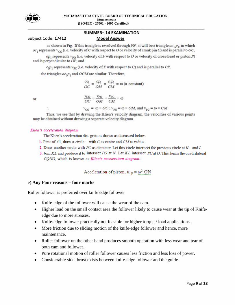
e) Any Four reasons – four marks
Roller follower is preferred over knife edge follower
Knife-edge of the follower will cause the wear of the cam.
Higher load on the small contact area the follower likely to cause wear at the tip of Knife-
edge due to more stresses.
Knife-edge follower practically not feasible for higher torque / load applications.
More friction due to sliding motion of the knife-edge follower and hence, more
maintenance.
Roller follower on the other hand produces smooth operation with less wear and tear of
both cam and follower.
Pure rotational motion of roller follower causes less friction and less loss of power.
Considerable side thrust exists between knife-edge follower and the guide.
MAHARASHTRA STATE BOARD OF TECHNICAL EDUCATION (Autonomous)
(ISO/IEC - 27001 - 2005 Certified)
____________________________________________________________________________________________
SUMMER– 14 EXAMINATION Subject Code: 17412 Model Answer
Page 10 of 28
f) Data: Initial tension, To = 2000 N, coefficient of friction, µ = 0.3,
Angle of lap, θ = 1500 =
1500 x П / 180 = 2.618 rad, Smaller pulley radius, R = 200 mm, hence, D
= 400 mm, Speed of smaller pulley, N = 500 r.p.m.
We know that the velocity of the belt, v = П
=
П
= 10.47 m/sec (01 mark)
Let T1 = Tension in the belt on the tight side, N
Let T2 = Tension in the belt on the slack side, N
We know that, T0 =
Hence, 2000 = (T1 + T2) / 2
Thus, (T1 + T2) = 4000 N ....................... (1)
We also know that,
= therefore,
= or
= 2.2 ............. (2)
From equations 1 and 2, T1 = 2750 N and T2 = 1250 N (02 marks)
Power transmitted by belt, P = [T1 - T2] v
= [2750 - 1250] 10.47
= 15700 watts = 15.7 kW (01 mark)
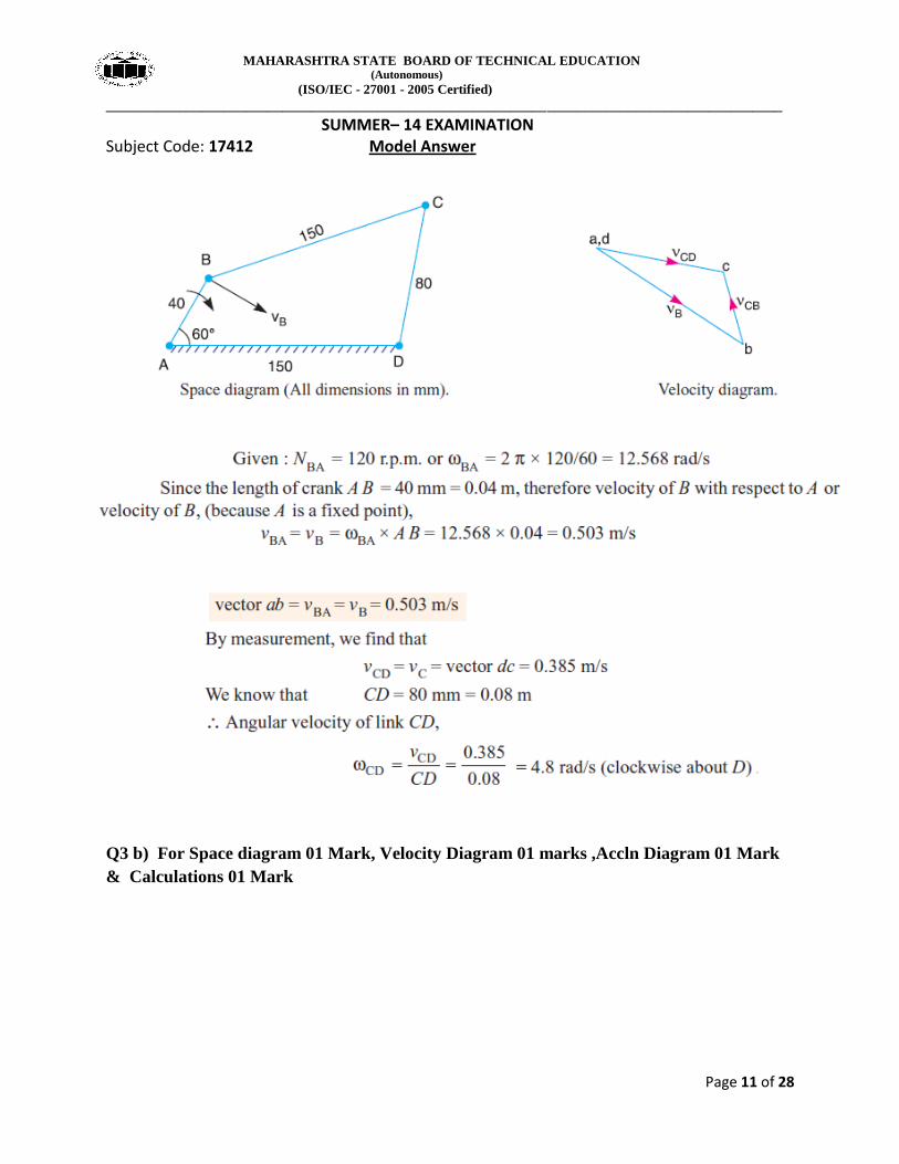
Q3 a) For Space diagram 01 Mark, Velocity Diagram 02 marks , Calculations 01 Mark
( Note In QP length BC & AB are equal. Read length AD = length BC = 150 mm)
MAHARASHTRA STATE BOARD OF TECHNICAL EDUCATION (Autonomous)
(ISO/IEC - 27001 - 2005 Certified)
____________________________________________________________________________________________
SUMMER– 14 EXAMINATION Subject Code: 17412 Model Answer
Page 11 of 28
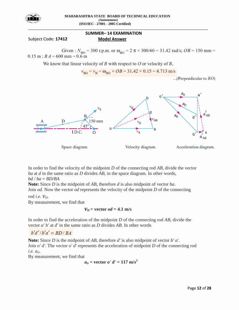
Q3 b) For Space diagram 01 Mark, Velocity Diagram 01 marks ,Accln Diagram 01 Mark
& Calculations 01 Mark
MAHARASHTRA STATE BOARD OF TECHNICAL EDUCATION (Autonomous)
(ISO/IEC - 27001 - 2005 Certified)
____________________________________________________________________________________________
SUMMER– 14 EXAMINATION Subject Code: 17412 Model Answer
Page 12 of 28
In order to find the velocity of the midpoint D of the connecting rod AB, divide the vector
ba at d in the same ratio as D divides AB, in the space diagram. In other words,
bd / ba = BD/BA
Note: Since D is the midpoint of AB, therefore d is also midpoint of vector ba.
Join od. Now the vector od represents the velocity of the midpoint D of the connecting
rod i.e. vD.
By measurement, we find that
vD = vector od = 4.1 m/s
In order to find the acceleration of the midpoint D of the connecting rod AB, divide the
vector a' b' at d' in the same ratio as D divides AB. In other words
Note: Since D is the midpoint of AB, therefore d' is also midpoint of vector b' a'.
Join o' d'. The vector o' d' represents the acceleration of midpoint D of the connecting rod
i.e. aD.
By measurement, we find that
aD = vector o' d' = 117 m/s2
MAHARASHTRA STATE BOARD OF TECHNICAL EDUCATION (Autonomous)
(ISO/IEC - 27001 - 2005 Certified)
____________________________________________________________________________________________
SUMMER– 14 EXAMINATION Subject Code: 17412 Model Answer
Page 13 of 28
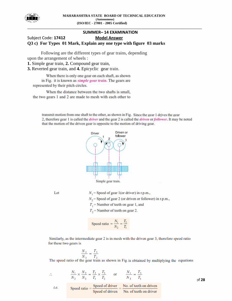
Q3 c) For Types 01 Mark, Explain any one type with figure 03 marks
Following are the different types of gear trains, depending
upon the arrangement of wheels :
1. Simple gear train, 2. Compound gear train,
3. Reverted gear train, and 4. Epicyclic gear train.
MAHARASHTRA STATE BOARD OF TECHNICAL EDUCATION (Autonomous)
(ISO/IEC - 27001 - 2005 Certified)
____________________________________________________________________________________________
SUMMER– 14 EXAMINATION Subject Code: 17412 Model Answer
Page 14 of 28
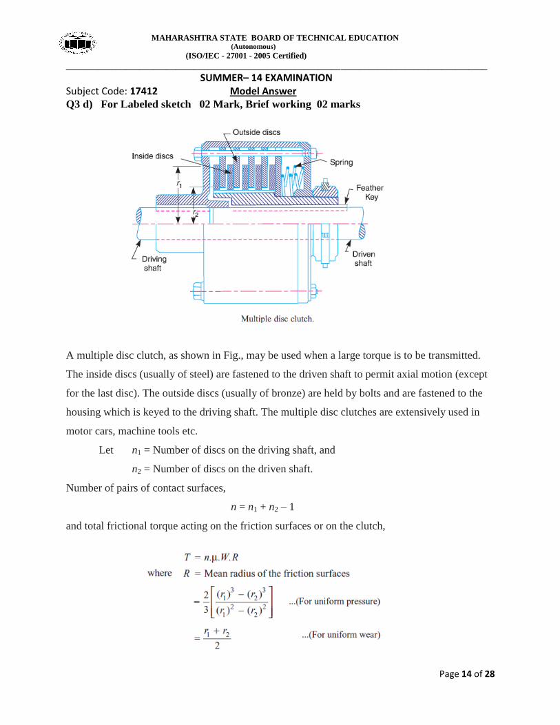
Q3 d) For Labeled sketch 02 Mark, Brief working 02 marks
A multiple disc clutch, as shown in Fig., may be used when a large torque is to be transmitted.
The inside discs (usually of steel) are fastened to the driven shaft to permit axial motion (except
for the last disc). The outside discs (usually of bronze) are held by bolts and are fastened to the
housing which is keyed to the driving shaft. The multiple disc clutches are extensively used in
motor cars, machine tools etc.
Let n1 = Number of discs on the driving shaft, and
n2 = Number of discs on the driven shaft.
Number of pairs of contact surfaces,
n = n1 + n2 – 1
and total frictional torque acting on the friction surfaces or on the clutch,
MAHARASHTRA STATE BOARD OF TECHNICAL EDUCATION (Autonomous)
(ISO/IEC - 27001 - 2005 Certified)
____________________________________________________________________________________________
SUMMER– 14 EXAMINATION Subject Code: 17412 Model Answer
Page 15 of 28
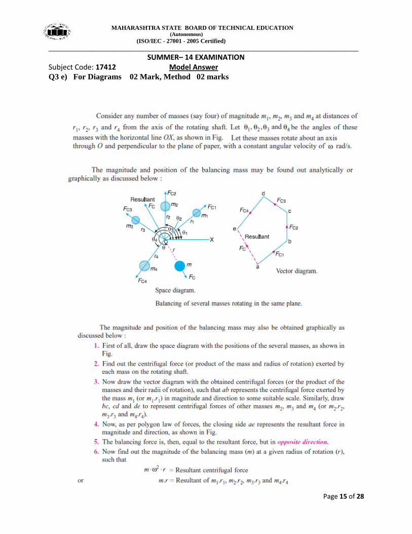
Q3 e) For Diagrams 02 Mark, Method 02 marks
MAHARASHTRA STATE BOARD OF TECHNICAL EDUCATION (Autonomous)
(ISO/IEC - 27001 - 2005 Certified)
____________________________________________________________________________________________
SUMMER– 14 EXAMINATION Subject Code: 17412 Model Answer
Page 16 of 28
f) For follower motions 02 Mark, for cam motions 02 marks
The follower, during its travel, may have one of the following motions.
1. Uniform velocity,
2. Simple harmonic motion,
3. Uniform acceleration and retardation,
4. Cycloidal motion.
In addition follower may have
1. Translatory motion
2. Oscillating motion
Also the cam may have one of the following motions
1. Rotary motion ( as in radial / cylindrical cam)
2. Linear motion ( as in wedge cam)
Q4 a) For equation 02 Mark, for terms 02 marks
Where T1 = Tension in the belt on the tight side,
T2 = Tension in the belt on the slack side, and
Ѳ = Angle of contact or lap in radians i.e angle subtended by the belt arc lapping
over small pulley.
MAHARASHTRA STATE BOARD OF TECHNICAL EDUCATION (Autonomous)
(ISO/IEC - 27001 - 2005 Certified)
____________________________________________________________________________________________
SUMMER– 14 EXAMINATION Subject Code: 17412 Model Answer
Page 17 of 28
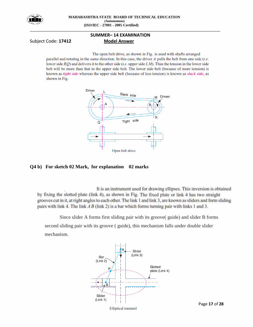
Q4 b) For sketch 02 Mark, for explanation 02 marks
Since slider A forms first sliding pair with its groove( guide) and slider B forms
second sliding pair with its groove ( guide), this mechanism falls under double slider
mechanism.
MAHARASHTRA STATE BOARD OF TECHNICAL EDUCATION (Autonomous)
(ISO/IEC - 27001 - 2005 Certified)
____________________________________________________________________________________________
SUMMER– 14 EXAMINATION Subject Code: 17412 Model Answer
Page 18 of 28
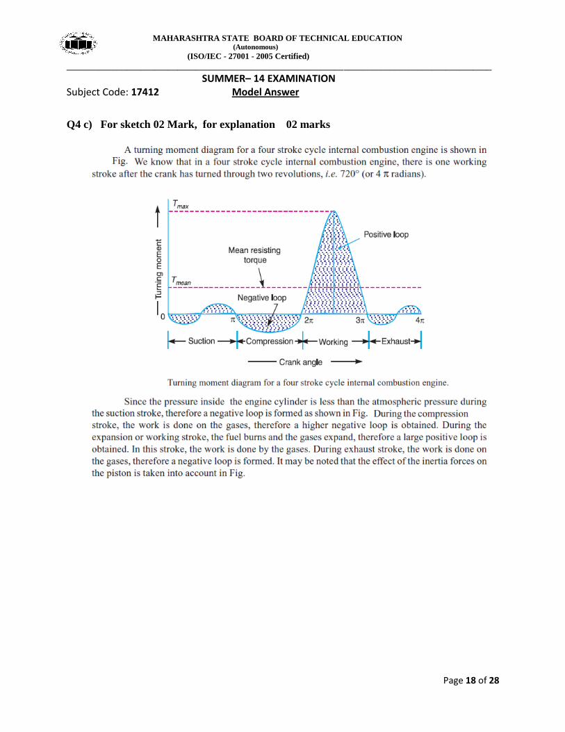
Q4 c) For sketch 02 Mark, for explanation 02 marks
MAHARASHTRA STATE BOARD OF TECHNICAL EDUCATION (Autonomous)
(ISO/IEC - 27001 - 2005 Certified)
____________________________________________________________________________________________
SUMMER– 14 EXAMINATION Subject Code: 17412 Model Answer
Page 19 of 28
Q4 d) For sketch 02 Mark, for explanation 02 marks
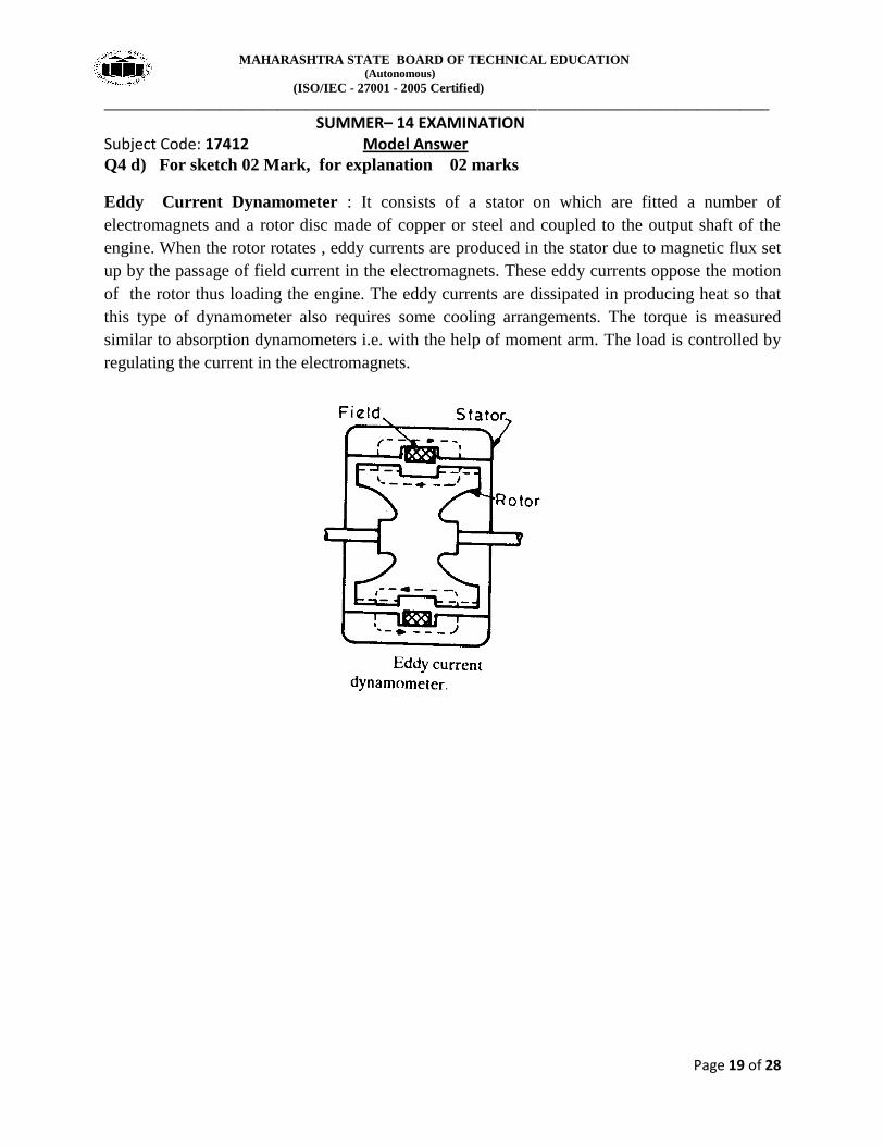
Eddy Current Dynamometer : It consists of a stator on which are fitted a number of
electromagnets and a rotor disc made of copper or steel and coupled to the output shaft of the
engine. When the rotor rotates , eddy currents are produced in the stator due to magnetic flux set
up by the passage of field current in the electromagnets. These eddy currents oppose the motion
of the rotor thus loading the engine. The eddy currents are dissipated in producing heat so that
this type of dynamometer also requires some cooling arrangements. The torque is measured
similar to absorption dynamometers i.e. with the help of moment arm. The load is controlled by
regulating the current in the electromagnets.
MAHARASHTRA STATE BOARD OF TECHNICAL EDUCATION (Autonomous)
(ISO/IEC - 27001 - 2005 Certified)
____________________________________________________________________________________________
SUMMER– 14 EXAMINATION Subject Code: 17412 Model Answer
Page 20 of 28
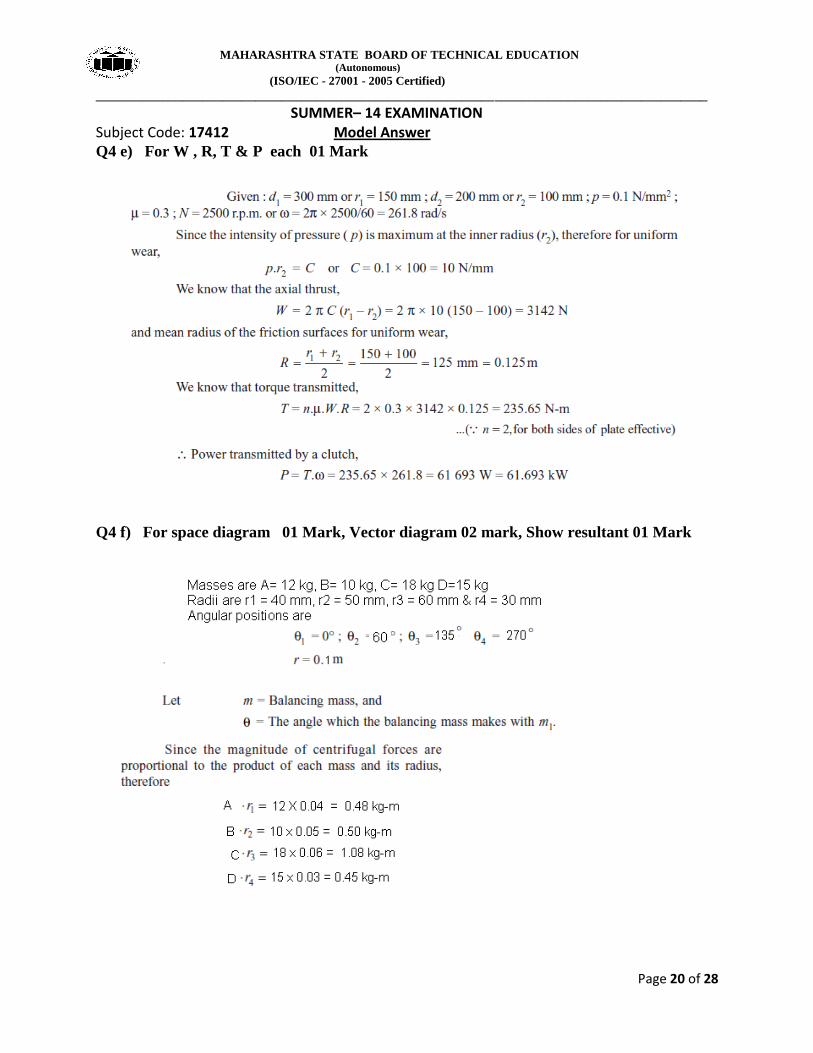
Q4 e) For W , R, T & P each 01 Mark
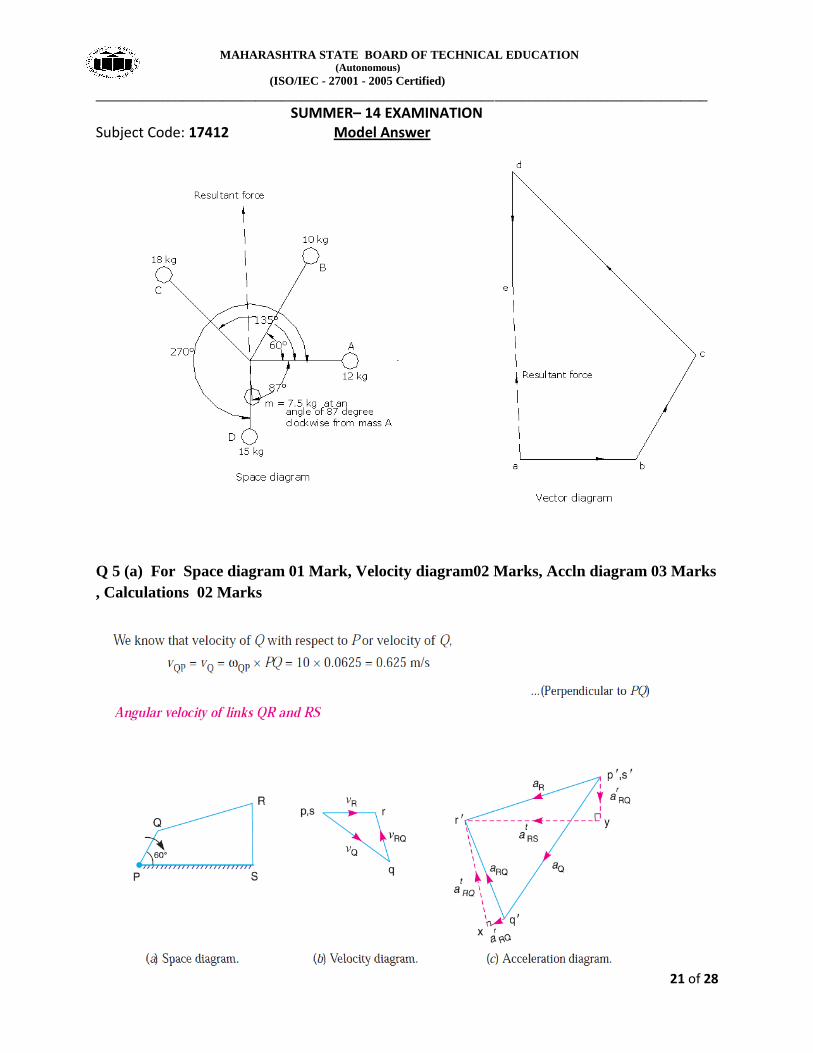
Q4 f) For space diagram 01 Mark, Vector diagram 02 mark, Show resultant 01 Mark
MAHARASHTRA STATE BOARD OF TECHNICAL EDUCATION (Autonomous)
(ISO/IEC - 27001 - 2005 Certified)
____________________________________________________________________________________________
SUMMER– 14 EXAMINATION Subject Code: 17412 Model Answer
Page 21 of 28
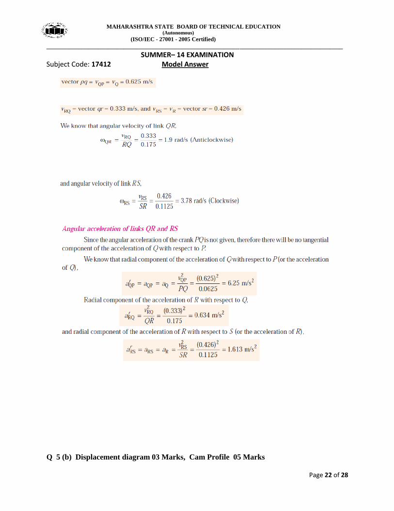
Q 5 (a) For Space diagram 01 Mark, Velocity diagram02 Marks, Accln diagram 03 Marks
, Calculations 02 Marks
MAHARASHTRA STATE BOARD OF TECHNICAL EDUCATION (Autonomous)
(ISO/IEC - 27001 - 2005 Certified)
____________________________________________________________________________________________
SUMMER– 14 EXAMINATION Subject Code: 17412 Model Answer
Page 22 of 28
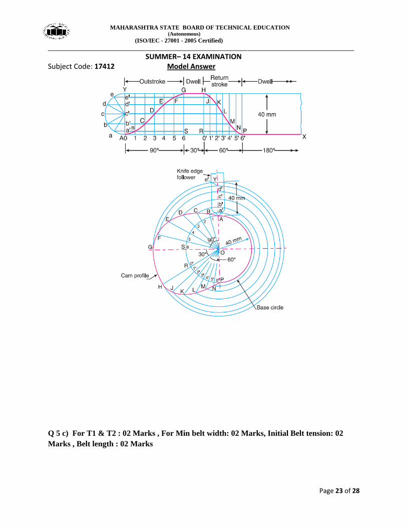
Q 5 (b) Displacement diagram 03 Marks, Cam Profile 05 Marks
MAHARASHTRA STATE BOARD OF TECHNICAL EDUCATION (Autonomous)
(ISO/IEC - 27001 - 2005 Certified)
____________________________________________________________________________________________
SUMMER– 14 EXAMINATION Subject Code: 17412 Model Answer
Page 23 of 28
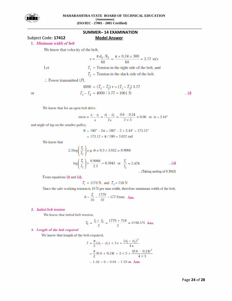
Q 5 c) For T1 & T2 : 02 Marks , For Min belt width: 02 Marks, Initial Belt tension: 02
Marks , Belt length : 02 Marks
MAHARASHTRA STATE BOARD OF TECHNICAL EDUCATION (Autonomous)
(ISO/IEC - 27001 - 2005 Certified)
____________________________________________________________________________________________
SUMMER– 14 EXAMINATION Subject Code: 17412 Model Answer
Page 24 of 28
MAHARASHTRA STATE BOARD OF TECHNICAL EDUCATION (Autonomous)
(ISO/IEC - 27001 - 2005 Certified)
____________________________________________________________________________________________
SUMMER– 14 EXAMINATION Subject Code: 17412 Model Answer
Page 25 of 28
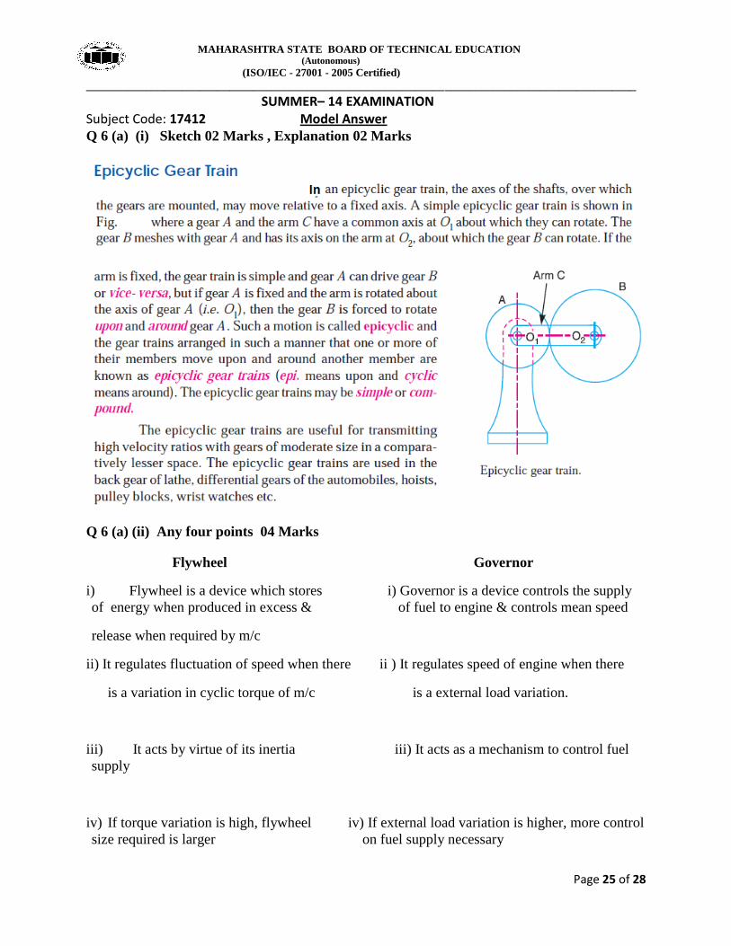
Q 6 (a) (i) Sketch 02 Marks , Explanation 02 Marks
Q 6 (a) (ii) Any four points 04 Marks
Flywheel Governor
i) Flywheel is a device which stores i) Governor is a device controls the supply
of energy when produced in excess & of fuel to engine & controls mean speed
release when required by m/c
ii) It regulates fluctuation of speed when there ii ) It regulates speed of engine when there
is a variation in cyclic torque of m/c is a external load variation.
iii) It acts by virtue of its inertia iii) It acts as a mechanism to control fuel
supply
iv) If torque variation is high, flywheel iv) If external load variation is higher, more control
size required is larger on fuel supply necessary
MAHARASHTRA STATE BOARD OF TECHNICAL EDUCATION (Autonomous)
(ISO/IEC - 27001 - 2005 Certified)
____________________________________________________________________________________________
SUMMER– 14 EXAMINATION Subject Code: 17412 Model Answer
Page 26 of 28
v) Used in Engines, forging m/c, Sheet v) Used in Engines
metal press, shearing m/c
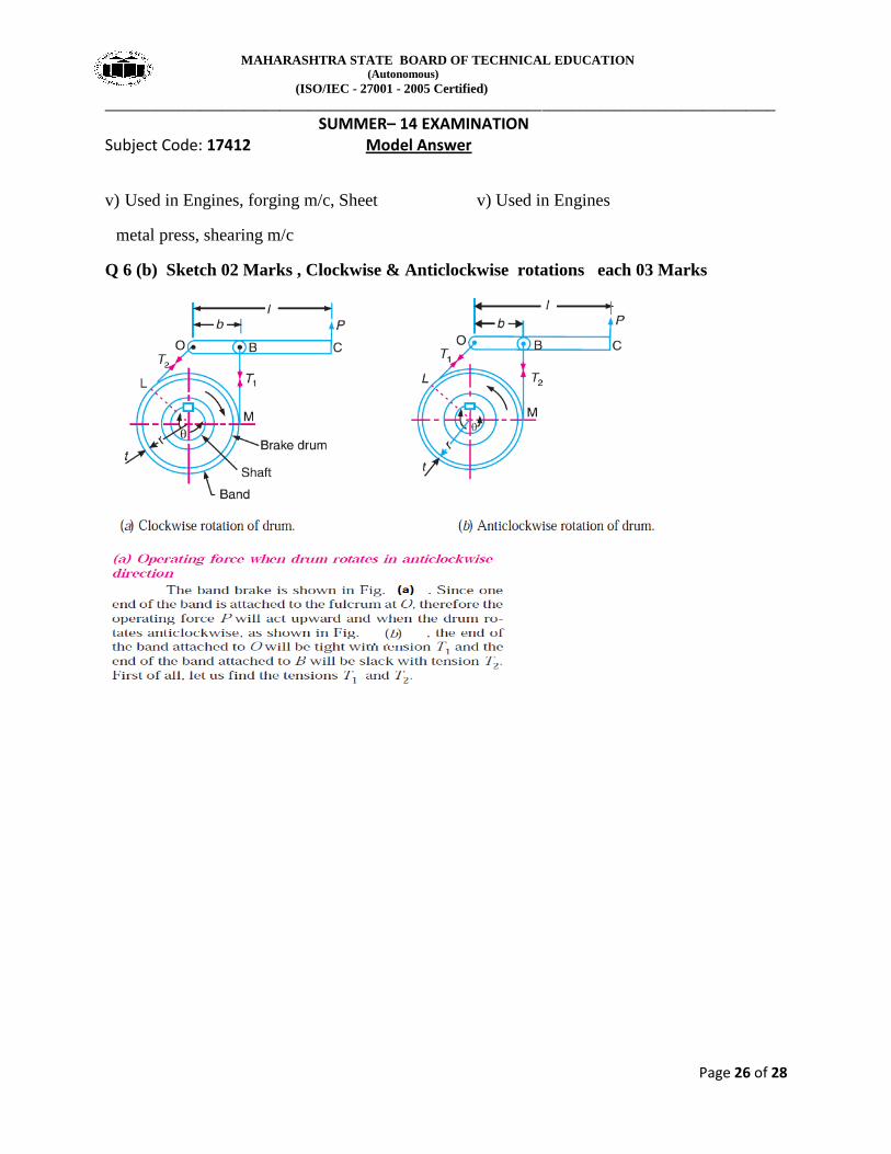
Q 6 (b) Sketch 02 Marks , Clockwise & Anticlockwise rotations each 03 Marks
MAHARASHTRA STATE BOARD OF TECHNICAL EDUCATION (Autonomous)
(ISO/IEC - 27001 - 2005 Certified)
____________________________________________________________________________________________
SUMMER– 14 EXAMINATION Subject Code: 17412 Model Answer
Page 27 of 28
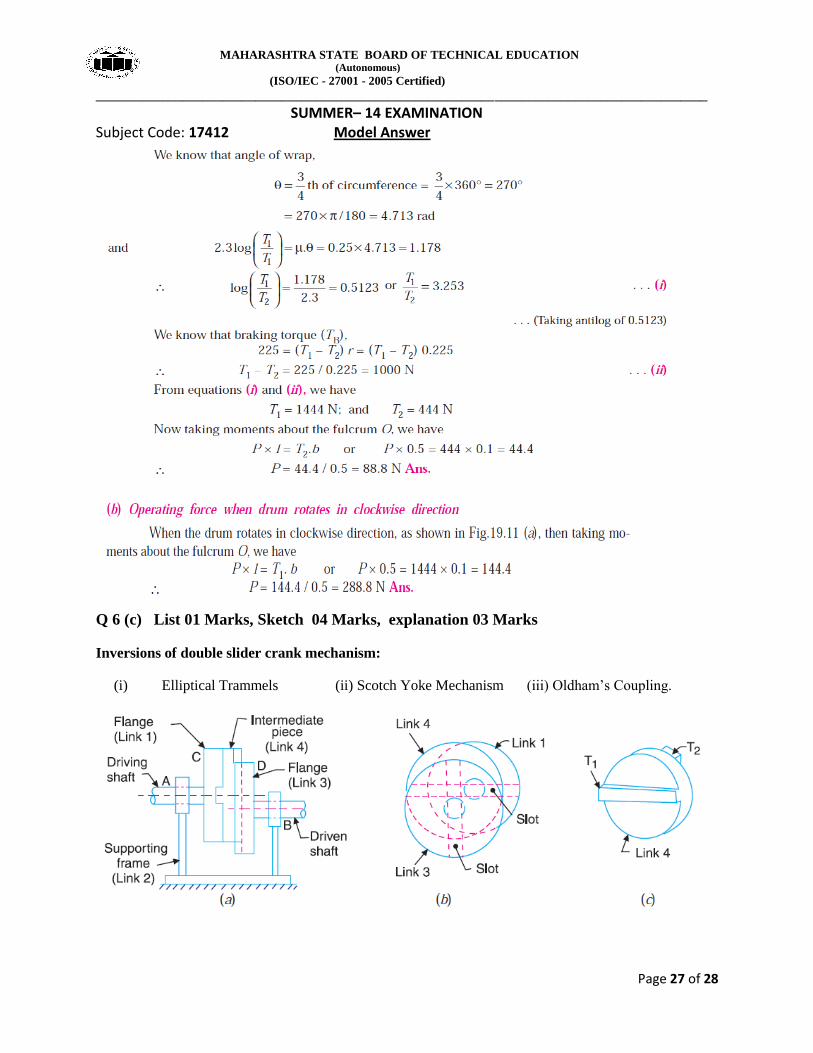
Q 6 (c) List 01 Marks, Sketch 04 Marks, explanation 03 Marks
Inversions of double slider crank mechanism:
(i) Elliptical Trammels (ii) Scotch Yoke Mechanism (iii) Oldham’s Coupling.
MAHARASHTRA STATE BOARD OF TECHNICAL EDUCATION (Autonomous)
(ISO/IEC - 27001 - 2005 Certified)
____________________________________________________________________________________________
SUMMER– 14 EXAMINATION Subject Code: 17412 Model Answer
Page 28 of 28