automotive research center robotics and mechatronics a nonlinear tracking controller for a haptic...
TRANSCRIPT
Automotive Research CenterRobotics and MechatronicsRobotics and Mechatronics
A Nonlinear Tracking Controller for a A Nonlinear Tracking Controller for a Haptic Interface Steer-by-Wire SystemsHaptic Interface Steer-by-Wire Systems
P. Setlur, D. Dawson, J. Chen, and J. WagnerDepartments of Mechanical and Electrical/Computer Engineering
Conference on Decision and Control, December 2002, Las Vegas
CLEMSONU N I V E R S I T Y
Automotive Research CenterRobotics and MechatronicsRobotics and Mechatronics
Presentation OutlinePresentation Outline
• Introduction– System Description and Problem Statement– Problem Motivation– Past Research
• Model Development– System model– Reference model concepts
• Adaptive Control Design– Error Definitions– Control Design– Stability Proof
• Extension to Eliminate Torque Measurements• Numerical Simulation Results• Experimental Results
– Setup– Preliminary Results
• Conclusion
Automotive Research CenterRobotics and MechatronicsRobotics and Mechatronics
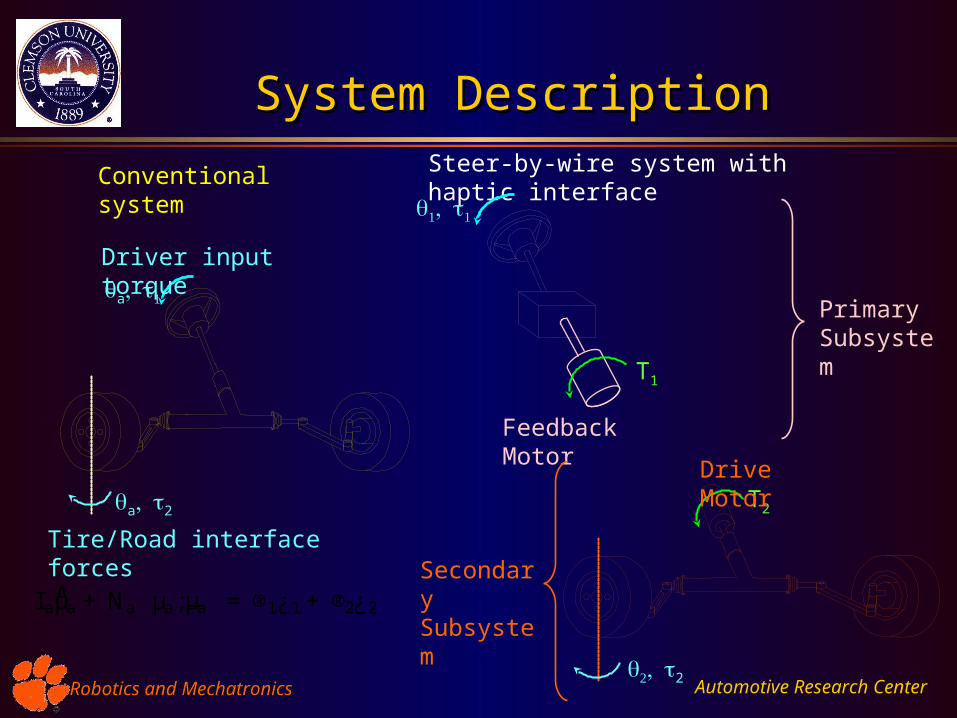
System DescriptionSystem DescriptionSteer-by-wire system with haptic interfaceConventional system
Primary Subsystem
T1
Feedback Motor
Secondary Subsystem
2
T2
Drive Motor a2
a
Tire/Road interface forces
Driver input torque
I aĵa + Na
³µa; _µa
´= ®1¿1 + ®2¿2
Automotive Research CenterRobotics and MechatronicsRobotics and Mechatronics
Problem MotivationProblem Motivation
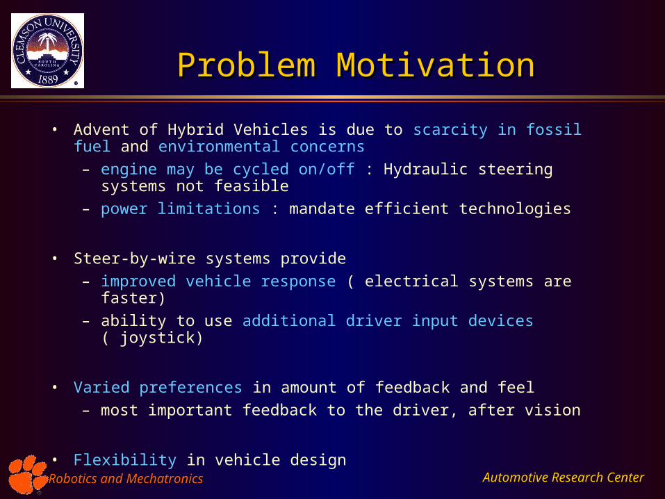
• Advent of Hybrid Vehicles is due to scarcity in fossil fuel and environmental concerns
– engine may be cycled on/off : Hydraulic steering systems not feasible
– power limitations : mandate efficient technologies
• Steer-by-wire systems provide
– improved vehicle response ( electrical systems are faster)
– ability to use additional driver input devices ( joystick)
• Varied preferences in amount of feedback and feel
– most important feedback to the driver, after vision
• Flexibility in vehicle design
Automotive Research CenterRobotics and MechatronicsRobotics and Mechatronics
Haptic Interface - GoalsHaptic Interface - Goals
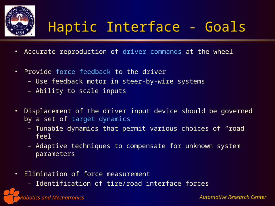
• Accurate reproduction of driver commands at the wheel
• Provide force feedback to the driver
– Use feedback motor in steer-by-wire systems
– Ability to scale inputs
• Displacement of the driver input device should be governed by a set of target dynamics
– Tunable dynamics that permit various choices of “road feel”
– Adaptive techniques to compensate for unknown system parameters
• Elimination of force measurement
– Identification of tire/road interface forces
Automotive Research CenterRobotics and MechatronicsRobotics and Mechatronics
Past ResearchPast Research
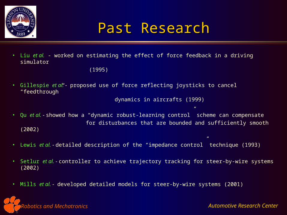
• Liu et al. - worked on estimating the effect of force feedback in a driving simulator
(1995)
• Gillespie et al. - proposed use of force reflecting joysticks to cancel “feedthrough”
dynamics in aircrafts (1999)
• Qu et al. - showed how a “dynamic robust-learning control” scheme can compensate
for disturbances that are bounded and sufficiently smooth (2002)
• Lewis et al. - detailed description of the “impedance control” technique (1993)
• Setlur et al. - controller to achieve trajectory tracking for steer-by-wire systems (2002)
• Mills et al. - developed detailed models for steer-by-wire systems (2001)
Automotive Research CenterRobotics and MechatronicsRobotics and Mechatronics
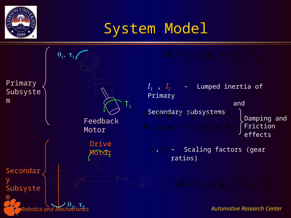
System ModelSystem Model
I 1ĵ1 + N1
³µ1; _µ1
´= ®1¿1 + T1
I 2ĵ2 + N2
³µ2; _µ2
´= ®2¿2 +T2
Secondary Subsystem
Primary Subsystem
I1 , I2 - Lumped inertia of Primary
and Secondary subsystems
N1
³µ1; _µ1
´= YN 1
³µ1; _µ1
´ÁN1 Damping and
Friction effects N2
³µ2; _µ2
´= YN 2
³µ2; _µ2
´ÁN 2
®1 ®2, - Scaling factors (gear ratios)
T1
Feedback Motor
2
T2
Drive Motor
Automotive Research CenterRobotics and MechatronicsRobotics and Mechatronics
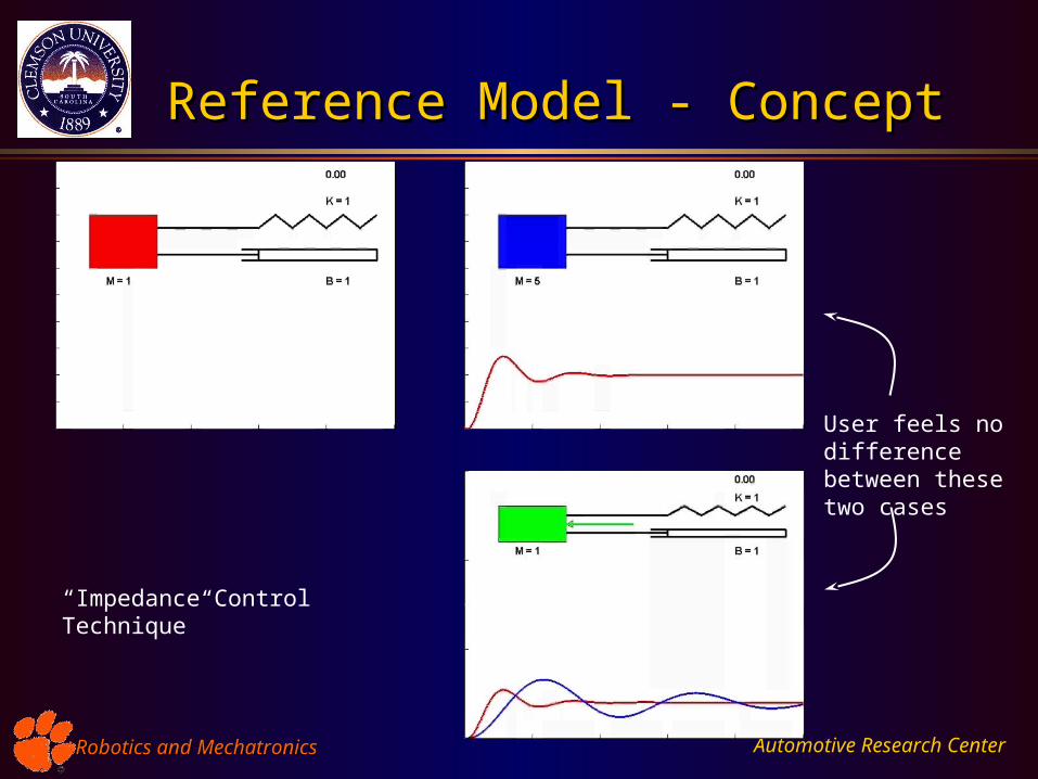
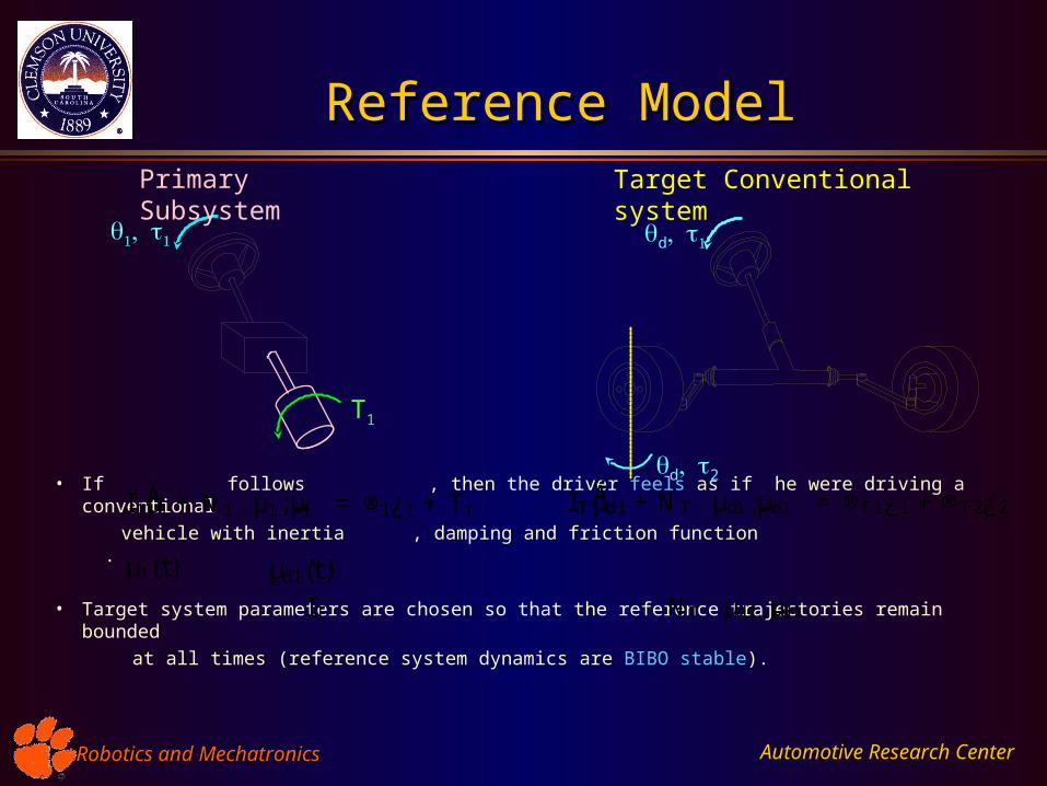
Reference Model - ConceptReference Model - Concept
User feels no difference between these two cases
“Impedance Control Technique”
Automotive Research CenterRobotics and MechatronicsRobotics and Mechatronics
• If follows , then the driver feels as if he were driving a conventional
vehicle with inertia , damping and friction function .
• Target system parameters are chosen so that the reference trajectories remain bounded
at all times (reference system dynamics are BIBO stable).
Reference ModelReference Model
I T ĵd1 +NT
³µd1; _µd1
´= ®T 1¿1 +®T 2¿2
Target Conventional system
d2
d
I 1ĵ1 + N1
³µ1; _µ1
´= ®1¿1 + T1
T1
Primary Subsystem
µ1(t) µd1(t)I T NT
³µd1; _µd1
´
Automotive Research CenterRobotics and MechatronicsRobotics and Mechatronics
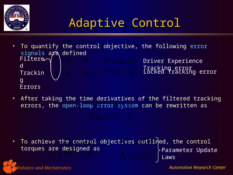
• To quantify the control objective, the following error signals are defined
• After taking the time derivatives of the filtered tracking errors, the open-loop error system can be rewritten as
• To achieve the control objectives outlined, the control torques are designed as
r1 = _e1 +¹ 1e1
r2 = _e2 +¹ 2e2
e1 = µd1 ¡ µ1
e2 = µ1 ¡ µ2:
Filtered Tracking Errors
I 1 _r1 = Y1Á1 ¡ T1
I 2 _r2 = Y2Á2 ¡ T2
Adaptive ControlAdaptive Control
Driver Experience Tracking error
Locked Tracking error
T1 = k1r1 + Y1Á̂1
T2 = k2r2 + Y2Á̂2
¢
Á̂1= ¡ 1Y T1 r1
¢
Á̂2= ¡ 2Y T2 r2
Parameter Update Laws
Automotive Research CenterRobotics and MechatronicsRobotics and Mechatronics
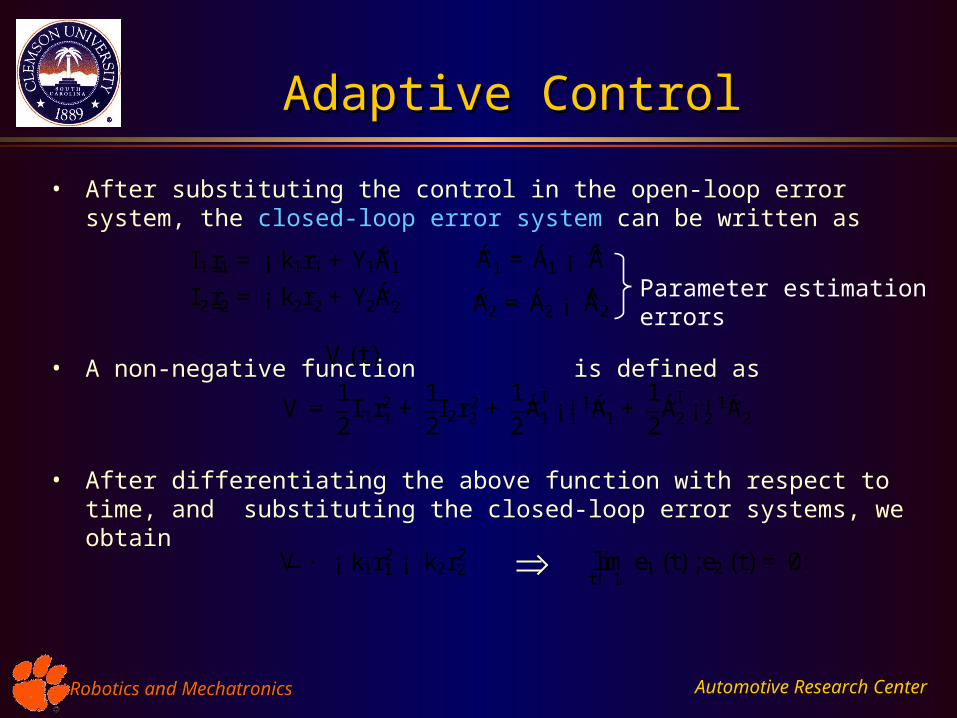
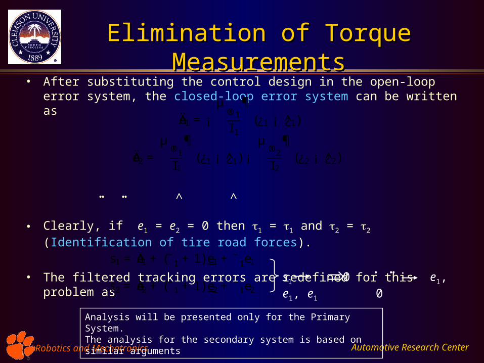
• After substituting the control in the open-loop error system, the closed-loop error system can be written as
• A non-negative function is defined as
• After differentiating the above function with respect to time, and substituting the closed-loop error systems, we obtain
limt! 1
e1 (t) ;e2 (t) = 0:
Adaptive ControlAdaptive Control
I 1 _r1 = ¡ k1r1 + Y1~Á1
I 2 _r2 = ¡ k2r2 + Y2~Á2
V (t)
V =12
I 1r21 +
12I 2r2
2 +12
~ÁT1 ¡ ¡ 1
1~Á1 +
12
~ÁT2 ¡ ¡ 1
2~Á2
~Á1 = Á1 ¡ Á̂
~Á2 = Á2 ¡ Á̂2Parameter estimation errors
_V · ¡ k1r21 ¡ k2r2
2
Automotive Research CenterRobotics and MechatronicsRobotics and Mechatronics
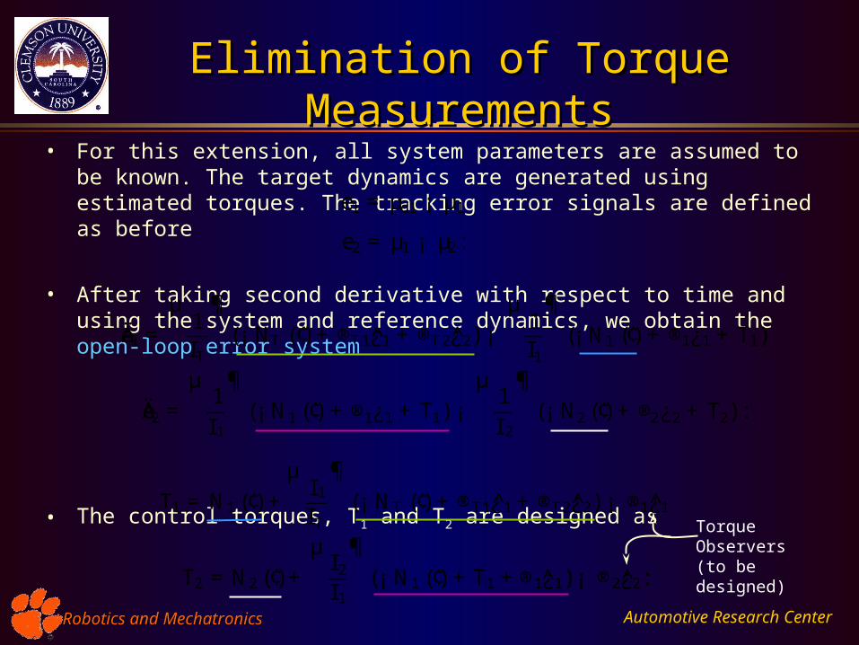
• For this extension, all system parameters are assumed to be known. The target dynamics are generated using estimated torques. The tracking error signals are defined as before
• After taking second derivative with respect to time and using the system and reference dynamics, we obtain the open-loop error system
• The control torques, T1 and T2 are designed as
Elimination of Torque MeasurementsElimination of Torque Measurements
e1 = µd1 ¡ µ1
e2 = µ1 ¡ µ2:
Äe1 =µ
1IT
¶(¡ NT (¢) + ®T 1¿̂1 + ®T 2¿̂2) ¡
µ1I1
¶(¡ N1 (¢) + ®1¿1 + T1)
Äe2 =µ
1I 1
¶(¡ N1 (¢) + ®1¿1 + T1) ¡
µ1I 2
¶(¡ N2 (¢) + ®2¿2 + T2) :
T1 = N1 (¢) +µ
I 1
I T
¶(¡ NT (¢) + ®T1¿̂1 + ®T 2¿̂2) ¡ ®1¿̂1
T2 = N2 (¢) +µ
I 2
I 1
¶(¡ N1 (¢) +T1 +®1¿̂1) ¡ ®2¿̂2:
Torque Observers(to be designed)
Automotive Research CenterRobotics and MechatronicsRobotics and Mechatronics
Elimination of Torque MeasurementsElimination of Torque Measurements• After substituting the control design in the open-loop error system, the closed-loop
error system can be written as
• Clearly, if e1 = e2 = 0 then 1 = 1 and 2 = 2 (Identification of tire road forces).
• The filtered tracking errors are redefined for this problem as
Äe1 =¡µ
®1
I 1
¶(¿1 ¡ ¿̂1)
Äe2 =µ
®1
I1
¶(¿1 ¡ ¿̂1) ¡
µ®2
I 2
¶(¿2 ¡ ¿̂2)
^ ^
s1 = Äe1 + (̄ 1 + 1) _e1 +¯1e1
s2 = Äe2 + (̄ 1 + 1) _e2 +¯1e2s1 0 e1, e1, e1 0
. ..
Analysis will be presented only for the Primary System. The analysis for the secondary system is based on similar arguments
.. ..
Automotive Research CenterRobotics and MechatronicsRobotics and Mechatronics
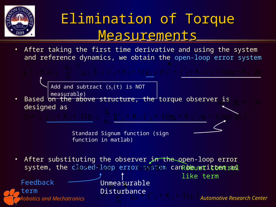
Elimination of Torque MeasurementsElimination of Torque Measurements
• After taking the first time derivative and using the system and reference dynamics, we obtain the open-loop error system
• Based on the above structure, the torque observer is designed as
• After substituting the observer in the open-loop error system, the closed-loop error system can be written as
_s1 = ¡ K ss1 ¡®1
I 1
µ_¿1¡
¢¿̂1 ¡ (¯1 + K s + 1)(¿1 ¡ ¿̂1)
¶+ (¯1 + K s (¯1 +1)) _e2 + K s¯ 1e2
¢¿̂1= ¡ (¯1 + K s + 1) ¿̂1 ¡
I 1
®1[(¯1 + K s (¯1 + 1)) _e1 +K s¯1e1 + ½1sgn(p1)]
_s1 = ¡ K ss1 ¡ ´1 ¡ ½1sgn (p1)
Standard Signum function (sign function in matlab)
Feedback term
´1 =µ
®1
I 1
¶(_¿1 +(¯1 + K s + 1) ¿1)
Unmeasurable Disturbance
Robust control like term
p1 = _e1 + ¯1e1
Add and subtract (s1(t) is NOT measurable)
Automotive Research CenterRobotics and MechatronicsRobotics and Mechatronics
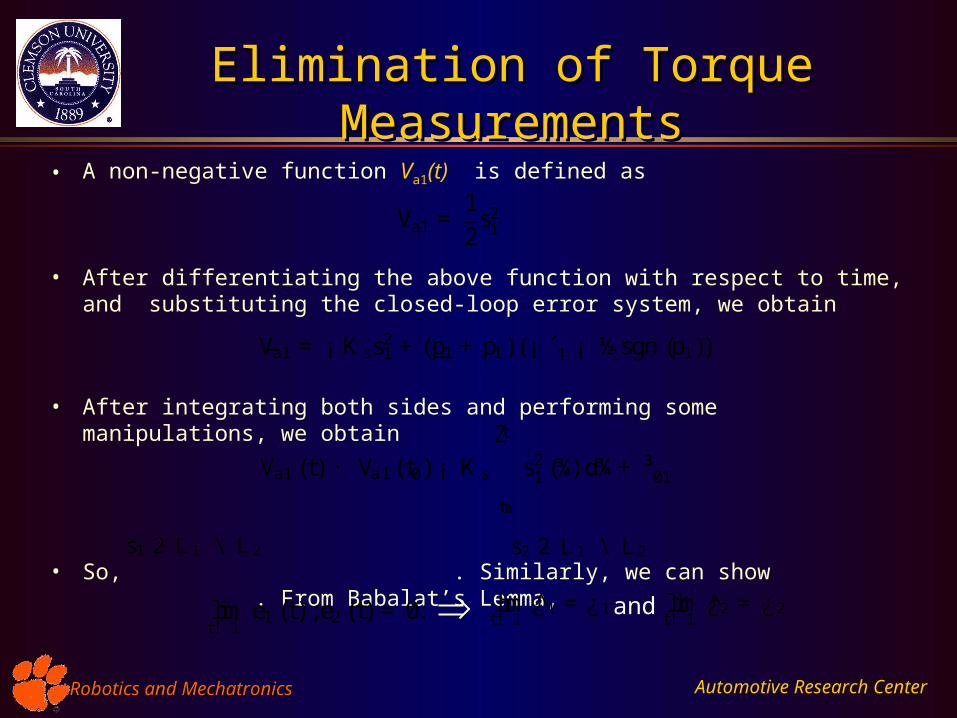
Elimination of Torque MeasurementsElimination of Torque Measurements
• A non-negative function Va1(t) is defined as
• After differentiating the above function with respect to time, and substituting the closed-loop error system, we obtain
• After integrating both sides and performing some manipulations, we obtain
• So, . Similarly, we can show . From Babalat’s Lemma,
Va1 =12
s21
_Va1 = ¡ K ss21 +( _p1 + p1)(¡ ´1 ¡ ½1sgn (p1))
Va1 (t) · Va1(t0) ¡ K s
tZ
t0
s21 (¾) d¾+ ³01
s1 2 L 1 \ L 2 s2 2 L 1 \ L 2
limt! 1
e1 (t) ;e2 (t) = 0: limt! 1
¿̂1 =¿1 and limt! 1
¿̂2 = ¿2
Automotive Research CenterRobotics and MechatronicsRobotics and Mechatronics
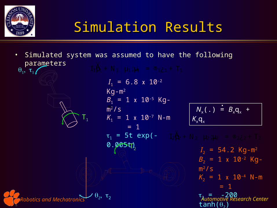
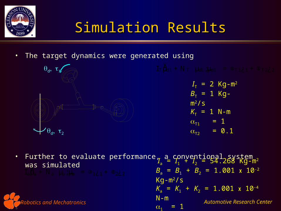
Simulation ResultsSimulation Results
• Simulated system was assumed to have the following parameters
I 1ĵ1 + N1
³µ1; _µ1
´= ®1¿1 + T1
I 2ĵ2 + N2
³µ2; _µ2
´= ®2¿2 +T2
I1 = 6.8 X 10⁻² Kg-m2
B1 = 1 X 10⁻⁵ Kg-m2/sK1 = 1 X 10⁻⁷ N-m = 11 = 5t exp(-0.005t)
®1
T1
2
T2
®2
I2 = 54.2 Kg-m2
B2 = 1 X 10⁻² Kg-m2/sK2 = 1 X 10⁻⁴ N-m = 12 = -200 tanh(2)
Nx(.) = Bxqx + Kxqx .
Automotive Research CenterRobotics and MechatronicsRobotics and Mechatronics
• The target dynamics were generated using
• Further to evaluate performance, a conventional system was simulated
Simulation ResultsSimulation Results
IT = 2 Kg-m2
BT = 1 Kg-m2/sKT = 1 N-mT1 = 1T2 = 0.1
I T ĵd1 +NT
³µd1; _µd1
´= ®T 1¿1 +®T 2¿2
d2
d
I aĵa + Na
³µa; _µa
´= ®1¿1 + ®2¿2
Ia = I1 + I2 = 54.268 Kg-m2
Ba = B1 + B2 = 1.001 X 10⁻² Kg-m2/sKa = K1 + K2 = 1.001 X 10⁻⁴ N-m1 = 12 = 1
Automotive Research CenterRobotics and MechatronicsRobotics and Mechatronics
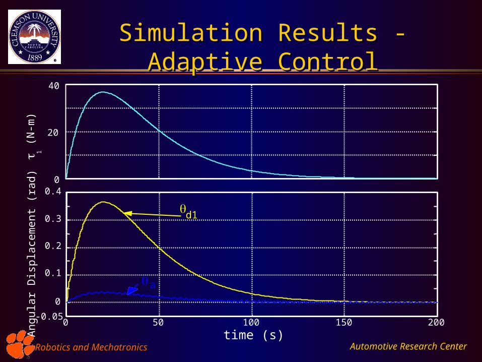
Simulation Results - Adaptive ControlSimulation Results - Adaptive Control
0 50 100 150 200
0
20
40
time (s)
1 (
N-m
)
-0.05
0
0.1
0.2
0.3
0.4
Ang
ular
Dis
plac
emen
t (ra
d)
d1
a
Automotive Research CenterRobotics and MechatronicsRobotics and Mechatronics
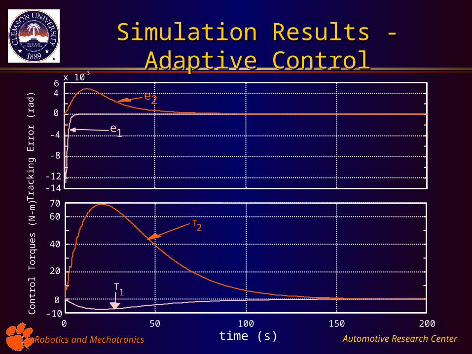
-14-12
-8
-4
0
46
x 10-3
Tra
ckin
g E
rror
(ra
d)
e1
e2
-10
0
20
40
60
70
Con
trol
Tor
ques
(N
-m)
T2
T1
0 50 100 150 200
time (s)
Simulation Results - Adaptive ControlSimulation Results - Adaptive Control
Automotive Research CenterRobotics and MechatronicsRobotics and Mechatronics
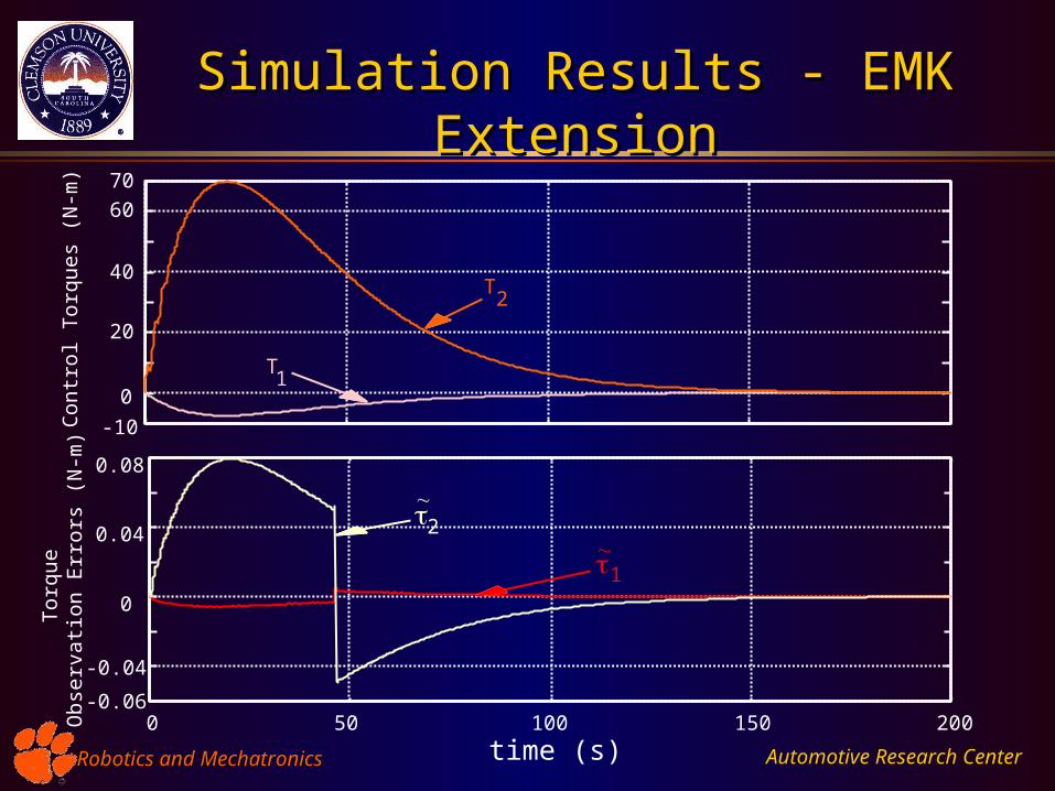
-10
0
20
40
60
70
Con
trol
Tor
ques
(N
-m)
0 50 100 150 200
time (s)
T1
T2
-0.06
-0.04
0
0.04
0.08
Tor
que
Obs
erva
tion
Err
ors
(N-m
)
2
1
Simulation Results - EMK ExtensionSimulation Results - EMK Extension
Automotive Research CenterRobotics and MechatronicsRobotics and Mechatronics
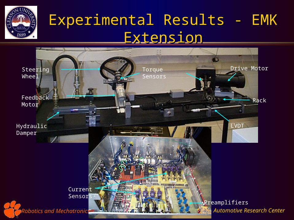
Experimental Results - EMK ExtensionExperimental Results - EMK Extension
Steering Wheel
Hydraulic Damper LVDT
Drive Motor
Feedback Motor Rack
Torque Sensors
Preamplifiers
Current Sensors
Automotive Research CenterRobotics and MechatronicsRobotics and Mechatronics
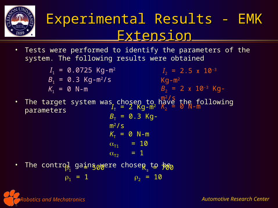
Experimental Results - EMK ExtensionExperimental Results - EMK Extension
• Tests were performed to identify the parameters of the system. The following results were obtained
• The target system was chosen to have the following parameters
• The control gains were chosen to be
I1 = 0.0725 Kg-m2
B1 = 0.3 Kg-m2/sK1 = 0 N-m
I2 = 2.5 X 10⁻³ Kg-m2
B2 = 2 X 10⁻³ Kg-m2/sK2 = 0 N-m
IT = 2 Kg-m2
BT = 0.3 Kg-m2/sKT = 0 N-mT1 = 10T2 = 1
1 = 500 Ks = 700 1 = 1 2 = 10
Automotive Research CenterRobotics and MechatronicsRobotics and Mechatronics
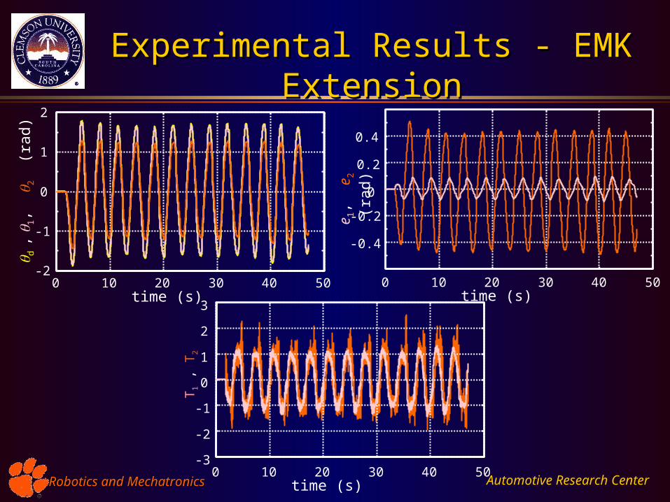
Experimental Results - EMK ExtensionExperimental Results - EMK Extension
-0.4
-0.2
0
0.2
0.4
e 1, e
2 (r
ad)
0 10 20 30 40 50time (s)
0 10 20 30 40 50-2
-1
0
1
2
time (s)
d , 1
, 2
(ra
d)
-3
-2
-1
0
1
2
3
T1 ,
T2
0 10 20 30 40 50time (s)
Automotive Research CenterRobotics and MechatronicsRobotics and Mechatronics
-4
-3
-2
-1
0
1
2
3
4
1 ,
1 (N
-m)
^
0 10 20 30 40 50time (s)
-3
-2
-1
0
1
2
3
4
5
2 ,
2 (N
-m)
^
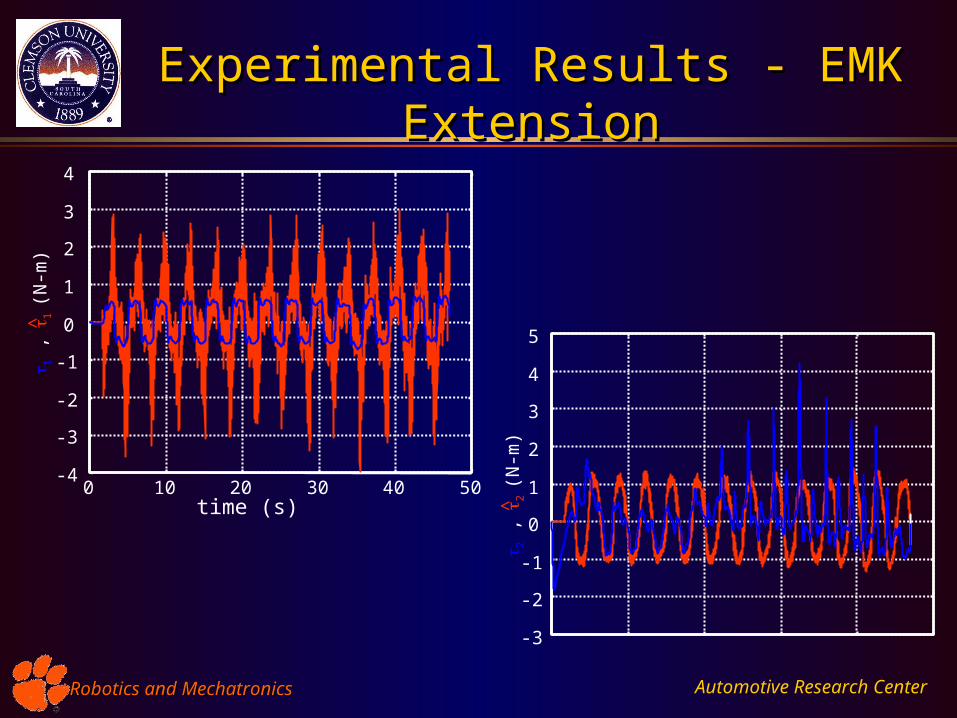
Experimental Results - EMK ExtensionExperimental Results - EMK Extension
Automotive Research CenterRobotics and MechatronicsRobotics and Mechatronics
Experimental Results - EMK ExtensionExperimental Results - EMK Extension
• Torque sensor measurements
– Noisy
– Drift
– Low resolution
• Target system dynamics involves twice integrating the torque signals for Adaptive control
• Gearing factor 1 and 2
• Torque capacity of the Feedback motor
• Repeatability of driver input - Choice of – larger value control torques have to change quickly (motors are
inductive systems)
Automotive Research CenterRobotics and MechatronicsRobotics and Mechatronics
Concluding RemarksConcluding Remarks
• Presented Vehicle Steering System Model for the Steer-by-wire configuration.
• Presented the Adaptive tracking control algorithm to ensure that
– vehicle follows driver commands
– driver is provided a haptic feedback
• Proposed an EMK extension that eliminates the need for torque sensor measurements
– identified tire/road interface forces
• Simulation Results verify the efficacy of the proposed control laws
• Preliminary Experimental Results were presented to discuss practical issues
• Future work would involve
– Control algorithm to compensation of parametric uncertainties without measurement of torque
– Incorporation of visual feedback for driver-in-loop tests