automotive capabilities - produktinfo.conrad.com · 2 automotive capabilities accelerating...
TRANSCRIPT
www.microchip.com/automotive
Automotive Capabilities
Automotive
2 Automotive Capabilities
Accelerating Distributed Intelligence in Tomorrow’s Vehicle
The evolution of electronics in the automotive market continues as the automotive system suppliers race to address the rigorous requirements of the automotive OEMs. The demands of our global automotive customers create new challenges and opportunities for innovation.
With many years of experience in delivering embedded solutions to automotive customers globally, the broad portfolio of products, development tools and design support from Microchip Technology enable creative solutions from the automotive system suppliers that are helping the automotive OEM deliver vehicles that have reduced fuel consumption with lower emissions and deliver a safer, more comfortable driving experience for the driver.
Our commitment to the automotive electronics market is demonstrated over the years by providing timely, quality solutions that lower total system cost. It doesn’t stop with just innovative products. Our leadership in manufacturing enables dependable delivery so that our customers have product when they need it. Plus Microchip’s Aggregate System supports our relentless quest for perfection.
The sustained success in automotive electronics for Microchip can be attributed to its focus on, both emerging and well established applications, where solutions from Microchip add value. Our customers can count on solutions which enable the customer’s ability to develop electronic modules that reduce the environmental impact in their quest to enhance fuel efficiency, reduce emissions and support sustainability.
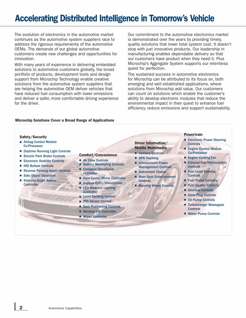
Microchip Solutions Cover a Broad Range of Applications
Safety/Security
■ Airbag Control Module Co-Processor
■ Daytime Running Light Controls
■ Electric Park Brake Controls
■ Electronic Stability Controls
■ HID Ballast Controls
■ Reverse Parking Assist Controls
■ Side Object Detection
■ Steering Angle Sensor Controller
Comfort/Convenience
■ Air Flow Controls■ Battery Monitoring Controls
■ Compass Directional Controller
■ Door Locks/Mirror Controller
■ Keyless Entry/Immobilizer
■ LED Ambient Lighting Controller
■ Level Sensing Control
■ PTC Heater Control
■ Seat Positioning Controls
■ Window Lift Controller
■ Wiper Controller
Driver Information/
Mobile Multimedia
■ Camera Controls
■ GPS Tracking
■ Infotainment Power Management Controls
■ Instrument Cluster
■ Rear Seat Entertainment Controls
■ Steering Wheel Controls
Powertrain
■ Electronic Power Steering Controls
■ Engine Control Module Co-Processor
■ Engine Cooling Fan
■ Exhaust Gas Recirculation Controls
■ Fuel Level Sensing Controls
■ Fuel Pump Controls
■ Fuel Quality Controls
■ Gearbox Controls
■ Glow Plug Controls
■ Oil Pump Controls
■ Turbocharger Wastegate Controls
■ Water Pump Controls
3
www.microchip.com/automotive
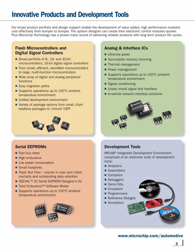
Flash Microcontrollers andDigital Signal Controllers
■ Broad portfolio of 8-, 16- and 32-bit microcontrollers, 16-bit digital signal controllers
■ From small, effi cient, nanoWatt microcontrollers to large, multi-function microcontrollers
■ Wide array of digital and analog peripheral functions
■ Easy migration paths
■ Supports operations up to 150ºC ambient temperature environment
■ Unifi ed development environment
■ Variety of package options from small, 6-pin leadless packages to 144-pin TQFP
Serial EEPROMs
■ Fast bus rates
■ High endurance
■ Low power consumption
■ Small footprints
■ Triple Test Flow – results in near zero infant mortality and outstanding data retention
■ SEEVAL™ 32 Serial EEPROM Designer’s Kit
■ Total Endurance™ Software Model
■ Supports operations up to 150ºC ambient temperature environment
Analog & Interface ICs
■ Ultra-low power
■ Non-volatile memory trimming
■ Thermal management
■ Power management
■ Supports operations up to 150ºC ambient temperature environment
■ Signal conditioning
■ Linear, mixed signal and interface
■ In-vehicle network interface solutions
Development Tools
MPLAB® Integrated Development Environment comprised of an extensive suite of development tools:
■ Analyzers
■ Assemblers
■ Compilers
■ Debuggers
■ Demo Kits
■ Emulators
■ Programmers
■ Reference Designs
■ Simulators
rs
Designs
Innovative Products and Development Tools
Our broad product portfolio and design support enable the development of value added, high performance modules cost effectively from bumper to bumper. The system designer can create their electronic control modules quicker. Plus Microchip Technology has a proven track record of delivering reliable products with long term product life cycles.
4 Automotive Capabilities
8-, 16- and 32-bit PIC®Microcontrollersand Digital Signal Controllers
Number one in market share since 2003, our 8-bit MCUs are the heart of Microchip’s business with over 6 billion MCUs integrated into consumer, industrial and automotive electronics*. From low cost, low power and small package
requirements to leading edge and feature rich performers, our devices are based on a powerful RISC core with industry-leading, self-programmable Flash. Our proven architecture and easy migration strategy is expanded into our 16- and 32-bit families to provide the same robust features with the added benefi ts of powerful peripherals to drive today’s high speed and low power electronics.
Microchip's broad product portfolio coupled with applications support and reference designs enable the automotive system designer to deliver cost effective solutions in an environment where fast time to market is essential. Microchip's continuous investments toward advancing semiconductor solutions enable a range of cost effective solutions. For example, LED lighting, motor control, mTouch sensing and battery monitoring are poised for further expansion.
Innovative Technologies Advancing Embedded Solutions in Vehicles
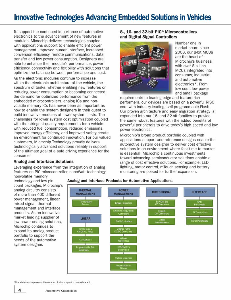
Analog and Interface Products for Automotive Applications
CAN
Peripherals
LIN Transceivers
Serial Peripherals
TemperatureSensors
Single-SupplyCMOS Op Amps
Comparators
Programmable GainAmplifiers
Linear Regulators
Switching Regulators/
Controllers
Voltage
References
CPU/SystemSupervisors
Charge PumpDC/DC Converters
Voltage Detectors
Power MOSFETDrivers
PWM Controllers
SAR/Del-SigA/D Converters
SystemD/A Converters
DigitalPotentiometers
INTERFACETHERMAL MANAGEMENT
POWERMANAGEMENT MIXED SIGNAL
LINEAR
*This statement represents the number of Microchip microcontrollers sold.
To support the continued importance of automotive electronics to the advancement of new features in modules, Microchip delivers technologies coupled with applications support to enable effi cient power management, improved human interface, increased conversion effi ciency, remote communications, data transfer and low power consumption. Designers are able to enhance their module’s performance, power effi ciency, connectivity and fl exibility with solutions that optimize the balance between performance and cost.
As the electronic modules continue to increase within the electronic architecture of the vehicle, the spectrum of tasks, whether enabling new features or reducing power consumption or becoming connected, the demand for optimized performance from the embedded microcontrollers, analog ICs and non-volatile memory ICs has never been as important as now to enable the system designers in their quest to build innovative modules at lower system costs. The challenges for lower system cost optimization coupled with the stringent quality requirements for a vehicle with reduced fuel consumption, reduced emissions, improved energy effi ciency, and improved safety create an environment for continued innovation. For our valued customers, Microchip Technology proudly delivers technologically advanced solutions reliably in support of the ultimate goal of a safe driving experience for the consumer.
Analog and Interface Solutions
Leveraging experience from the integration of analog features on PIC microcontroller, nanoWatt technology, nonvolatile memory technology and low pin count packages, Microchip’s analog circuitry consists of more than 400 different power management, linear, mixed signal, thermal management and interface products. As an innovative market leading supplier of low power analog solutions, Microchip continues to expand its analog product portfolio to support the needs of the automotive system designer.
5
Driving nanoWatt XLP into Tomorrow’s Vehicles
With increased electronics penetration across the broad spectrum of applications within the vehicle, the number of ECMs continues to expand – taxing the vehicle's power budget. Some higher end vehicles can have over 80 ECMs, which means that current loads are increasing. An increase in battery size to support the growing power requirements is an alternative to overcoming this challenge. However, larger batteries do not always provide a good tradeoff in an environment where space is limited and weight is critical, due to the negative impact on fuel consumption.
A better alternative is to use nanoWatt XLP, Microchip's innovative solution to address the operational power consumption of the ECMs. Through a unique blend of design techniques, fl exible power management features and process technology, nanoWatt XLP technology allows engineers to manage static, active and average power consumption.
In those ECMs which consume power when the ignition is off, using nanoWatt XLP-based PIC microcontrollers, with industry leading low sleep currents, gives the system designer the abilty to tackle the power budget challenges.
www.microchip.com/XLP
PIC MCUs with nanoWatt Technology also support up to nine oscillator modes, which include:
■Ultra Low Power Wake-up (ULPW) mode – Reduces current draw during wake-up.
■Confi gurable Idle, Sleep and Deep Sleep modes – Let designers tailor current consumption levels
and clocking options to fi t any power budget.
■Advantageous two-speed start-up feature – Allows seamless transition by running from either
of the internal oscillators while an external clock source stabilizes on start-up. After the external source has stabilized, the MCU automatically makes a clock switch, saving precious “up” time.
■Clock frequency can be switched on the fl y – Allowing no delay in code execution on transitions
between external clocks and the internal oscillators.
Low Power Safety
In addition to peripherals, products with nanoWatt XLP have system supervisory circuits specially designed for battery powered products.
■ The Deep Sleep Brown-out Reset protects applications when batteries are depleted and changed, yet consumes a tiny 45 nA of current
■ The Real-time Clock Calendar module on products with Deep Sleep can continue to run provide precise time for less than 500 nA
■ Using a dedicated on-chip oscillator, the standard WDT and Deep Sleep WDT provide protection against system failure for less than 500 nA.
Benefi ts of nanoWatt XLP Technology:■ Sleep currents down to 20 nA■ Brown-out Reset down to 45 nA■ Watch-dog Timer down to 400 nA■Real-time Clock/Calendar down to 500 nA
6 Automotive Capabilities
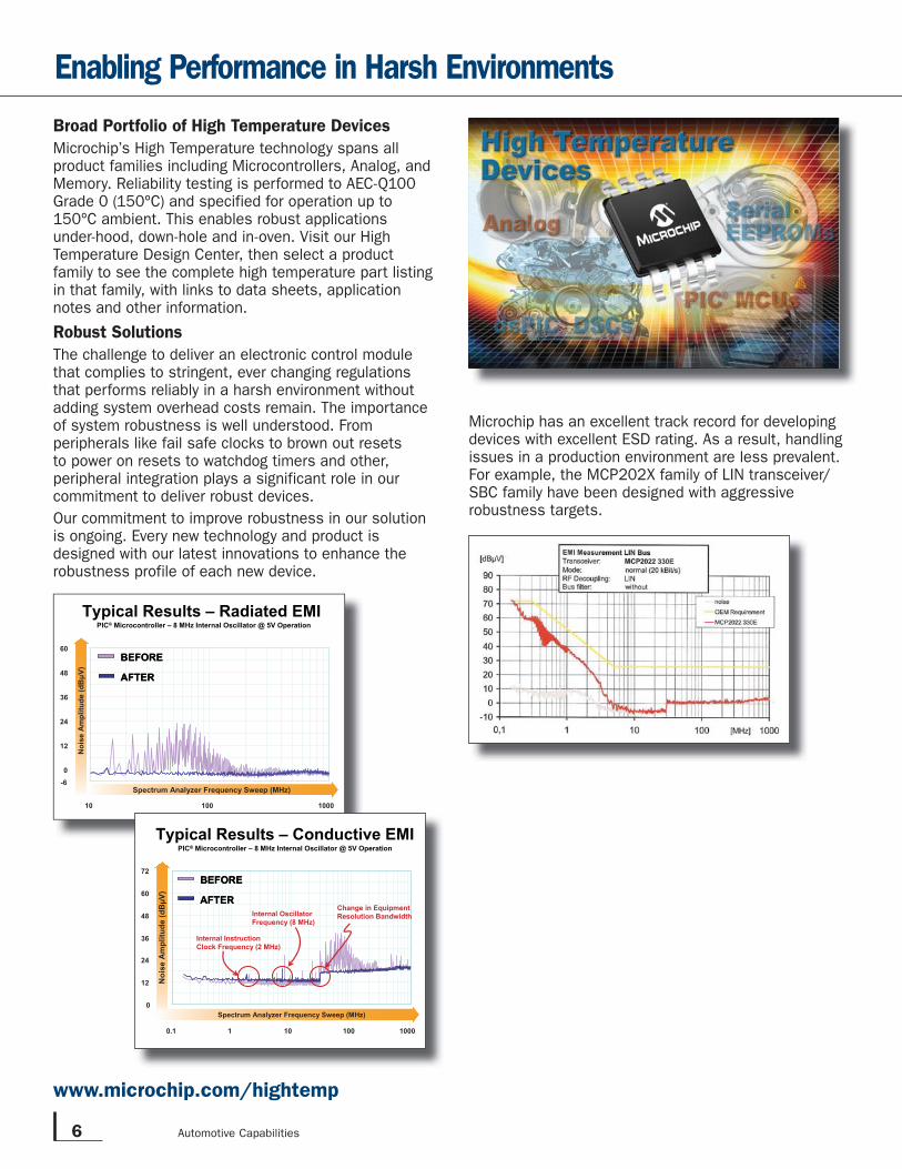
Microchip has an excellent track record for developing devices with excellent ESD rating. As a result, handling issues in a production environment are less prevalent. For example, the MCP202X family of LIN transceiver/SBC family have been designed with aggressive robustness targets.
Enabling Performance in Harsh Environments
-60
12
24
36
48
60
10 100 1000
Noi
se A
mpl
itude
(dB
µV)
Spectrum Analyzer Frequency Sweep (MHz)
BEFORE
AFTER
BEFORE
AFTER
Typical Results – Radiated EMI PIC® Microcontroller – 8 MHz Internal Oscillator @ 5V Operation
µN
oise
Am
plitu
de (d
BV)
Spectrum Analyzer Frequency Sweep (MHz)0
12
24
36
48
60
72
0.1 1 10 100 1000
Internal Oscillator Frequency (8 MHz)
Internal InstructionClock Frequency (2 MHz)
Change in EquipmentResolution Bandwidth
Typical Results – Conductive EMI
BEFORE
AFTER
BEFORE
AFTER
PIC®® Microcontroller – 8 MHz Internal Oscillator @ 5V Operation
Broad Portfolio of High Temperature Devices
Microchip’s High Temperature technology spans all product families including Microcontrollers, Analog, and Memory. Reliability testing is performed to AEC-Q100 Grade 0 (150ºC) and specified for operation up to 150ºC ambient. This enables robust applications under-hood, down-hole and in-oven. Visit our High Temperature Design Center, then select a product family to see the complete high temperature part listing in that family, with links to data sheets, application notes and other information.
Robust Solutions
The challenge to deliver an electronic control module that complies to stringent, ever changing regulations that performs reliably in a harsh environment without adding system overhead costs remain. The importance of system robustness is well understood. From peripherals like fail safe clocks to brown out resets to power on resets to watchdog timers and other, peripheral integration plays a significant role in our commitment to deliver robust devices.
Our commitment to improve robustness in our solution is ongoing. Every new technology and product is designed with our latest innovations to enhance the robustness profile of each new device.
www.microchip.com/hightemp
7
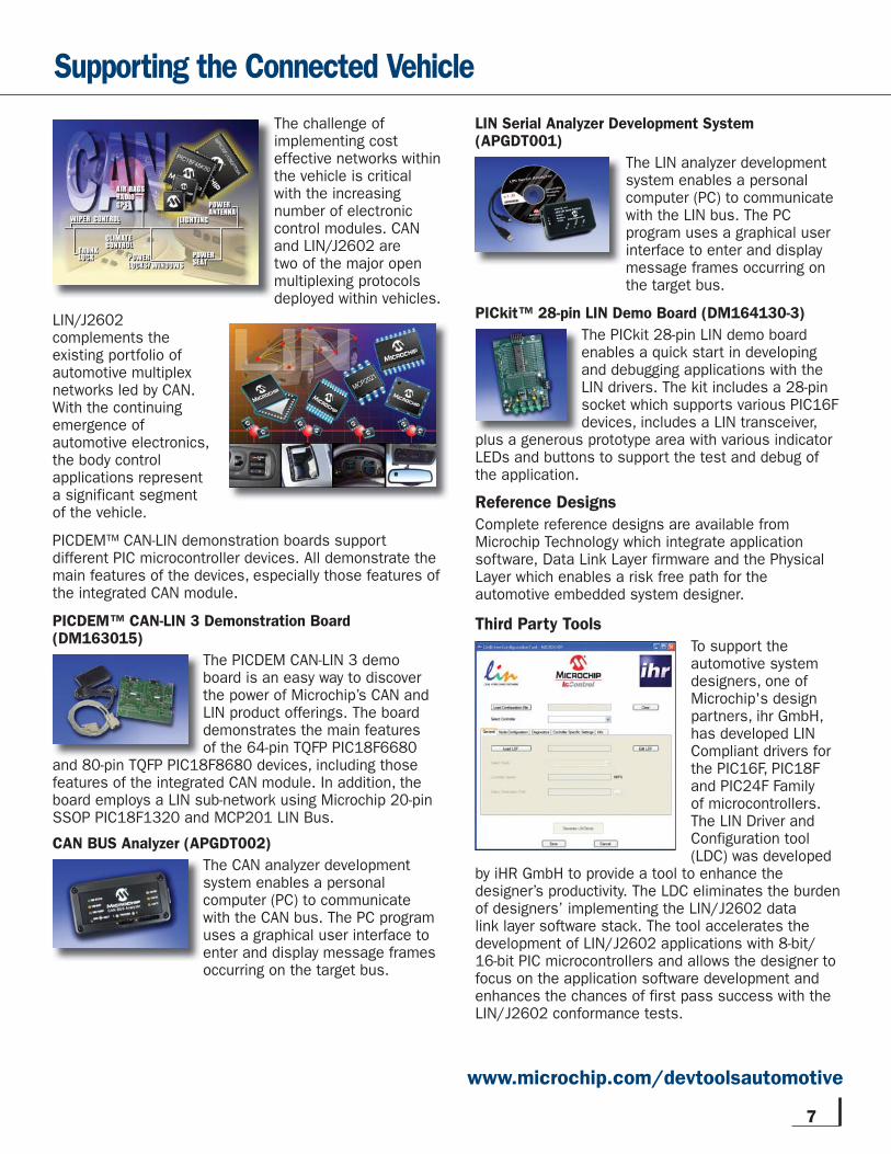
The challenge of implementing cost effective networks within the vehicle is critical with the increasing number of electronic control modules. CAN and LIN/J2602 are two of the major open multiplexing protocols deployed within vehicles.
LIN/J2602 complements the existing portfolio of automotive multiplex networks led by CAN. With the continuing emergence of automotive electronics, the body control applications represent a significant segment of the vehicle.
PICDEM™ CAN-LIN demonstration boards support different PIC microcontroller devices. All demonstrate the main features of the devices, especially those features of the integrated CAN module.
PICDEM™ CAN-LIN 3 Demonstration Board(DM163015)
The PICDEM CAN-LIN 3 demo board is an easy way to discover the power of Microchip’s CAN and LIN product offerings. The board demonstrates the main features of the 64-pin TQFP PIC18F6680
and 80-pin TQFP PIC18F8680 devices, including those features of the integrated CAN module. In addition, the board employs a LIN sub-network using Microchip 20-pin SSOP PIC18F1320 and MCP201 LIN Bus.
CAN BUS Analyzer (APGDT002)
The CAN analyzer development system enables a personal computer (PC) to communicate with the CAN bus. The PC program uses a graphical user interface to enter and display message frames occurring on the target bus.
LIN Serial Analyzer Development System (APGDT001)
The LIN analyzer development system enables a personal computer (PC) to communicate with the LIN bus. The PC program uses a graphical user interface to enter and display message frames occurring on the target bus.
PICkit™ 28-pin LIN Demo Board (DM164130-3)
The PICkit 28-pin LIN demo board enables a quick start in developing and debugging applications with the LIN drivers. The kit includes a 28-pin socket which supports various PIC16F devices, includes a LIN transceiver,
plus a generous prototype area with various indicator LEDs and buttons to support the test and debug of the application.
Reference Designs
Complete reference designs are available from Microchip Technology which integrate application software, Data Link Layer firmware and the Physical Layer which enables a risk free path for the automotive embedded system designer.
Third Party Tools
To support the automotive system designers, one of Microchip's design partners, ihr GmbH, has developed LIN Compliant drivers for the PIC16F, PIC18F and PIC24F Family of microcontrollers. The LIN Driver and Configuration tool (LDC) was developed
by iHR GmbH to provide a tool to enhance the designer’s productivity. The LDC eliminates the burden of designers’ implementing the LIN/J2602 data link layer software stack. The tool accelerates the development of LIN/J2602 applications with 8-bit/16-bit PIC microcontrollers and allows the designer to focus on the application software development and enhances the chances of first pass success with the LIN/J2602 conformance tests.
Supporting the Connected Vehicle
l
www.microchip.com/devtoolsautomotive
8 Automotive Capabilities
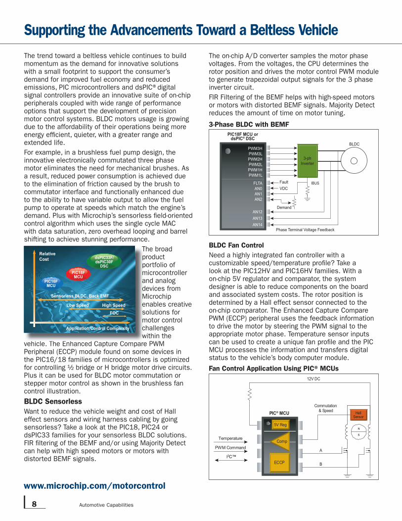
The on-chip A/D converter samples the motor phase voltages. From the voltages, the CPU determines the rotor position and drives the motor control PWM module to generate trapezoidal output signals for the 3 phase inverter circuit.
FIR Filtering of the BEMF helps with high-speed motors or motors with distorted BEMF signals. Majority Detect reduces the amount of time on motor tuning.
BLDC Fan Control
Need a highly integrated fan controller with a customizable speed/temperature profi le? Take a look at the PIC12HV and PIC16HV families. With a on-chip 5V regulator and comparator, the system designer is able to reduce components on the board and associated system costs. The rotor position is determined by a Hall effect sensor connected to the on-chip comparator. The Enhanced Capture Compare PWM (ECCP) peripheral uses the feedback information to drive the motor by steering the PWM signal to the appropriate motor phase. Temperature sensor inputs can be used to create a unique fan profi le and the PIC MCU processes the information and transfers digital status to the vehicle’s body computer module.
The trend toward a beltless vehicle continues to build momentum as the demand for innovative solutions with a small footprint to support the consumer’s demand for improved fuel economy and reduced emissions, PIC microcontrollers and dsPIC® digital signal controllers provide an innovative suite of on-chip peripherals coupled with wide range of performance options that support the development of precision motor control systems. BLDC motors usage is growing due to the affordability of their operations being more energy effi cient, quieter, with a greater range and extended life.
For example, in a brushless fuel pump design, the innovative electronically commutated three phase motor eliminates the need for mechanical brushes. As a result, reduced power consumption is achieved due to the elimination of friction caused by the brush to commutator interface and functionally enhanced due to the ability to have variable output to allow the fuel pump to operate at speeds which match the engine’s demand. Plus with Microchip’s sensorless fi eld-oriented control algorithm which uses the single cycle MAC with data saturation, zero overhead looping and barrel shifting to achieve stunning performance.
The broad product portfolio of microcontroller and analog devices from Microchip enables creative solutions for motor control challenges within the
vehicle. The Enhanced Capture Compare PWM Peripheral (ECCP) module found on some devices in the PIC16/18 families of microcontrollers is optimized for controlling ½ bridge or H bridge motor drive circuits. Plus it can be used for BLDC motor commutation or stepper motor control as shown in the brushless fan control illustration.
BLDC Sensorless
Want to reduce the vehicle weight and cost of Hall effect sensors and wiring harness cabling by going sensorless? Take a look at the PIC18, PIC24 or dsPIC33 families for your sensorless BLDC solutions. FIR fi ltering of the BEMF and/or using Majority Detect can help with high speed motors or motors with distorted BEMF signals.
Supporting the Advancements Toward a Beltless Vehicle
N
S
HallSensor
PIC® MCU
12V DC
A
B
Temperature
PWM Command
I2C™
Commutation& Speed
5V Reg
ECCP
Comp
Fan Control Application Using PIC® MCUs
www.microchip.com/motorcontrol
3-ph
Inverter
IBUS
BLDC
Demand
Fault
VDC
PIC18F MCU ordsPIC® DSC
Phase Terminal Voltage Feedback
PWM3H
PWM3L
PWM2H
PWM2L
PWM1H
PWM1L
FLTA
AN0
AN1
AN2
AN12
AN13
AN14
3-Phase BLDC with BEMF
TppmadMesmcw
dsPIC33F/dsPIC30F
DSC
PIC16FMCU
PIC18FMCU
RelativeCost
Sensorless BLDC, Back EMF
Application/Control Complexity
Low Speed High SpeedFOC
9
Capacitive Touch Sensing
Microchip’s Capacitive mTouch Sensing Solution can be implemented with a number of PIC microcontrollers to satisfy the demands of a broad range of application requirements from the most basic single-button design using an incredibly small, cost effective 6-pin PIC10F to a multi button design using the appropriate peripheral rich 8-bit or 16-bit PIC microcontroller.
Inductive Touch Sensing
Microchip’s Inductive mTouch Sensing Solution can be implemented with existing application code in a single 8-, 16- or 32-bit PIC microcontroller or 16-bit dsPIC digital signal controller, thus reducing total system systems. The only peripherals required are a PWM and an analog to digital converter.
How to Choose the Right Capacitive Touch Solution for Your Application
The application ultimately dictates which solution best suits your design. For example:
ApplicationRequirement
DeviceFamily
One key or proximity sensor PIC10F Family
Up to four keys PIC16F Family
More than eight keys with communication; Low power < 10 μA
PIC16F Family
More than 8 keys with MCU performance, memory features
PIC24F Family
www.microchip.com/touch
Touch Sensing Technologies In Automotive
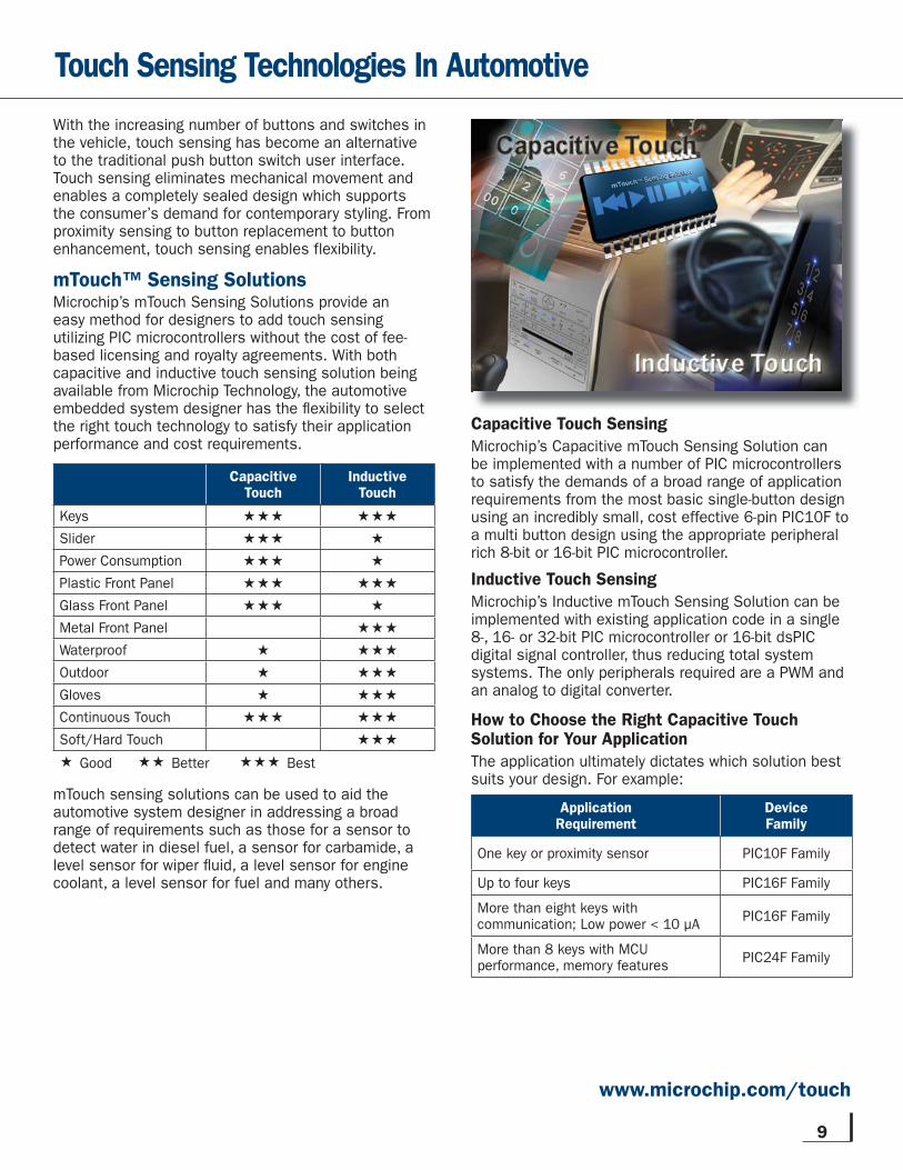
With the increasing number of buttons and switches in the vehicle, touch sensing has become an alternative to the traditional push button switch user interface. Touch sensing eliminates mechanical movement and enables a completely sealed design which supports the consumer’s demand for contemporary styling. From proximity sensing to button replacement to button enhancement, touch sensing enables flexibility.
mTouch™ Sensing SolutionsMicrochip’s mTouch Sensing Solutions provide an easy method for designers to add touch sensing utilizing PIC microcontrollers without the cost of fee-based licensing and royalty agreements. With both capacitive and inductive touch sensing solution being available from Microchip Technology, the automotive embedded system designer has the fl exibility to select the right touch technology to satisfy their application performance and cost requirements.
CapacitiveTouch
InductiveTouch
Keys Slider Power Consumption Plastic Front Panel Glass Front Panel Metal Front Panel Waterproof Outdoor Gloves Continuous Touch Soft/Hard Touch Good Better Best
mTouch sensing solutions can be used to aid the automotive system designer in addressing a broad range of requirements such as those for a sensor to detect water in diesel fuel, a sensor for carbamide, a level sensor for wiper fl uid, a level sensor for engine coolant, a level sensor for fuel and many others.
10 Automotive Capabilities
Automotive Ambient Lighting ModuleReference Design (APGRD004)
The Automotive Ambient Interior Lighting Module Reference Design demonstrates microcontroller-based control of RGB LED devices. This module can be controlled remotely
by a master body controller via a LIN bus. These modules are offered in a very compact form-factor board and are comprised of a PIC12F615 MCU, an MCP2021 LIN transceiver/voltage regulator, and RGB LED. LIN commands are interpreted by the module to control color mixing (16,383 colors) and intensity (1023 levels). The kit ships with 4 modules to assign as lighting zones in a LIN or J2602 network. These modules can also be used in conjunction with the APGDT001 LIN Serial Analyzer to quickly create a working LIN network straight out of the box.
Enabling LED Lighting Applications
With the advances in technology, LED lighting is being used in both interior and exterior applications within the vehicle. LEDs deliver long life, durability and efficiency. For example
in a practical exterlor lighting application such as daytime running lights, LED based daytime running lights improve road safety and reduce fuel consumption by approximately 0.2 liter/100 km when compared to using the head lamp operating in low beam mode. Plus LED daytime running lamps offer the vehicles a touch of individual styling.
Effi cient LED Control
LEDs must be driven with a source of constant current. Most LEDs have a specifi ed current level that will achieve the maximum brightness for that LED without premature failures. An LED could be driven with a linear voltage regulator confi gured as a constant current source. However, this approach is not practical for higher power LEDs due to power dissipation in the regulator circuit. A switch-mode power supply (SMPS) provides a much more effi cient solution to drive the LED. SMPS implementation with Microchip products can be analog, digital or mixed signal based solutions.
An LED will have a forward voltage drop across its terminals for a given current drive level. The power supply voltage and the LED forward voltage characteristics determine the SMPS topology that is required. Multiple LEDs can be connected in series to increase the forward voltage drop at the chosen drive current level.
The SMPS circuit topologies adopted to regulate current in LED lighting applications are the same used to control voltage in a power supply application. Each type of SMPS topology offers the system designer trade-offs as shown in the table below.
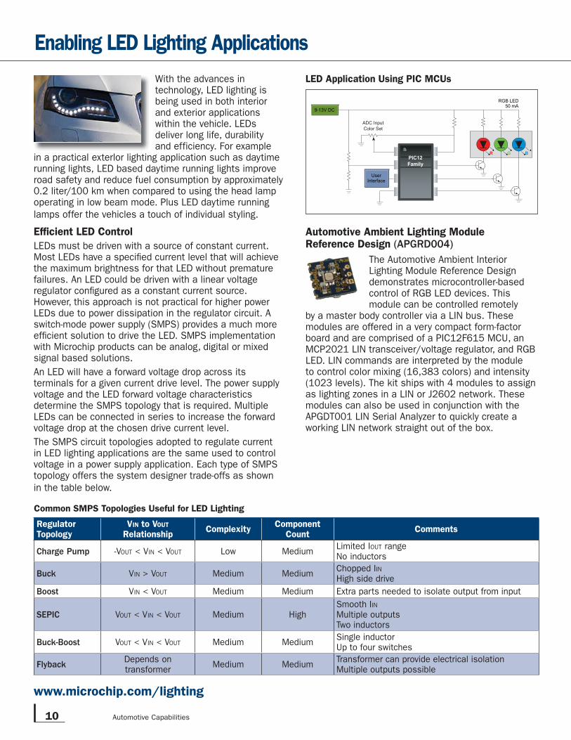
R BGPIC12Family
ADC Input
Color Set
RGB LED50 mA
9-13V DC
UserInterface
LED Application Using PIC MCUs
Common SMPS Topologies Useful for LED Lighting
RegulatorTopology
VIN to VOUT
RelationshipComplexity
ComponentCount
Comments
Charge Pump -VOUT < VIN < VOUT Low MediumLimited IOUT rangeNo inductors
Buck VIN > VOUT Medium MediumChopped IINHigh side drive
Boost VIN < VOUT Medium Medium Extra parts needed to isolate output from input
SEPIC VOUT < VIN < VOUT Medium HighSmooth IINMultiple outputsTwo inductors
Buck-Boost VOUT < VIN < VOUT Medium MediumSingle inductorUp to four switches
FlybackDepends ontransformer
Medium MediumTransformer can provide electrical isolationMultiple outputs possible
www.microchip.com/lighting
11
Commitment to the Relentless Quest for Perfection
Quality and Reliability
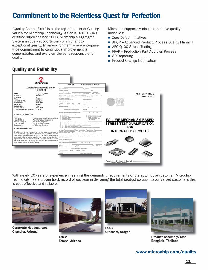
AUTOMOTIVE PRODUCTS GROUP 8-D REPORT
DATE: August 28, 2007 SUBJECT: defect VIA REVISION: A FA #: C070816 MICROCHIP P/N: 24LC16B Trace Code: 06443WV MASK NO.: C5AR3 CUSTOMER: TRW Customer Part #: 59141550 Customer Tracking Number: 204115
1. USE TEAM APPROACH:
Andy Birrell - Yield Enhancement Engineering Manager Roger Melcher - Wafer Manufacturing Engineer Anupam Menghal - APG Quality Engineer Craig Comeaux - Failure Analysis Engineer Steve Vernier - APG Product Engineer
2. DESCRIBE PROBLEM:
One 24LC16B device was returned when the customer reported that device is failed in end user applications. The device failure has been confirmed during bench testing as well as ATE testing. All the pins appeared normal during initial curve tracing. Bench testing revealed that the device was drawing abnormally high current. It is also confirmed that the multiple addresses in array are flipping with each read. The ATE testing also revealed that the returned unit may have failed the parametric or functional tests.
Part Submission WarrantPart Name Cust. Part Number
Shown on Drawing Number Orig. Part Number
Engineering Change Level Dated
Additional Engineering Changes N/A Dated
Safety and/or Government Regulation Purchase Order No. N/A
Checking Aid Number Checking Aid Eng. Change Level Dated
ORGANIZATION MANUFACTURING INFORMATION CUSTOMER SUBMITTAL INFORMATION
Organization Name & Supplier/Vendor Code Customer Name/Division
Street Address Buyer/Buyer Code
USACity Region Postal Code Country Application
MATERIALS REPORTING
Has customer-required Substances of Concern information been reported?
Submitted by IMDS or other customer format:
Are polymeric parts identified with appropriate ISO marking codes?
REASON FOR SUBMISSION (Check at least one)Initial submission Change to Optional Construction or MaterialEngineering Change(s) Sub-Supplier or Material Source ChangeTooling: Transfer, Replacement, Refurbishment, or additional Change in Part ProcessingCorrection of Discrepancy Parts produced at Additional LocationTooling Inactive > than 1 year Other - please specify
REQUESTED SUBMISSION LEVEL (Check one)Level 1 - Warrant only (and for designated appearance items, an Appearance Approval Report) submitted to customer.Level 2 - Warrant with product samples and limited supporting data submitted to customer.Level 3 - Warrant with product samples and complete supporting data submitted to customer.Level 4 - Warrant and other requirements as defined by customer.Level 5 - Warrant with product samples and complete supporting data reviewed at organization's manufacturing location.
SUBMISSION RESULTSThe results forThese results meet all design record requirements: (If "NO" - Explanation Required)Mold / Cavity / Production Process N/A
DECLARATION
EXPLANATION/COMMENTS:
Is each Customer Tool properly tagged and numbered?
Organization Authorized Signature Date
Print NameTitle Corporate Quality E-mail
FOR CUSTOMER USE ONLY (IF APPLICABLE)
PPAP Warrant Disposition:
Customer Signature Date
Print Name Customer Tracking Number (optional)
N/A
N/A Weight (kg)
Pb-Free N/A N/A
I affirm that the samples represented by this warrant are representative of our parts, which were made by a process that meets all ProductionPart Approval Process Manual 4th Edition Requirements. I further affirm that these samples were produced at the production rate of_N/A___/_N/A___ hours. I also certify that documented evidence of such compliance is on file and available for your review. I have noted anydeviation from this declaration below.
Chandler Arizona 85224
2355 W Chandler Blvd.
Microchip Technology Inc.
Phone No. Fax No.
Node ID#
PPAP#
480-792-4317
Yes NO
dimensional measurements material and functional tests appearance criteria statistical process package
Yes No
Yes No
Yes No
Approved Rejected Other
n/a
n/a
Yes No n/a
N/A
ductionrate ofted any
age
AEC - Q100 - Rev-GMay 14, 2007
FAILURE MECHANISM BASEDSTRESS TEST QUALIFICATION
FORINTEGRATED CIRCUITS
Component Technical CommitteeAutomotive Electronics Council
“Quality Comes First” is at the top of the list of Guiding Values for Microchip Technology. As an ISO/TS-16949 certified supplier since 2003, Microchip’s Aggregate System uniquely supports our commitment to exceptional quality. In an environment where enterprise wide commitment to continuous improvement is demonstrated and every employee is responsible for quality.
With nearly 20 years of experience in serving the demanding requirements of the automotive customer, Microchip Technology has a proven track record of success in delivering the total product solution to our valued customers that is cost effective and reliable.
Corporate HeadquartersChandler, ArizonaC t H d t
Fab 2Tempe, Arizona
Fab 4Gresham, Oregon
Product Assembly/TestBangkok, Thailand
www.microchip.com/quality
Microchip supports various automotive quality initiatives:
Zero Defect Initiatives
APQP – Advanced Product/Process Quality Planning
AEC-Q100 Stress Testing
PPAP – Production Part Approval Process
8D Reporting
Product Change Notification
AMERICAS
AtlantaTel: 678-957-9614
BostonTel: 774-760-0087
ChicagoTel: 630-285-0071
ClevelandTel: 216-447-0464
DallasTel: 972-818-7423
DetroitTel: 248-538-2250
KokomoTel: 765-864-8360
Los AngelesTel: 949-462-9523
Santa ClaraTel: 408-961-6444
TorontoMississauga, OntarioTel: 905-673-0699
EUROPE
Austria - WelsTel: 43-7242-2244-39
Denmark - CopenhagenTel: 45-4450-2828
France - ParisTel: 33-1-69-53-63-20
Germany - MunichTel: 49-89-627-144-0
Italy - MilanTel: 39-0331-742611
Netherlands - DrunenTel: 31-416-690399
Spain - MadridTel: 34-91-708-08-90
UK - WokinghamTel: 44-118-921-5869
ASIA/PACIFIC
Australia - SydneyTel: 61-2-9868-6733
China - BeijingTel: 86-10-8528-2100
China - ChengduTel: 86-28-8665-5511
China - Hong Kong SARTel: 852-2401-1200
China - NanjingTel: 86-25-8473-2460
China - QingdaoTel: 86-532-8502-7355
China - ShanghaiTel: 86-21-5407-5533
China - ShenyangTel: 86-24-2334-2829
China - ShenzhenTel: 86-755-8203-2660
China - WuhanTel: 86-27-5980-5300
China - XiamenTel: 86-592-2388138
China - XianTel: 86-29-8833-7252
China - ZhuhaiTel: 86-756-3210040
Sales Offi ce ListingASIA/PACIFIC
India - BangaloreTel: 91-80-3090-4444
India - New DelhiTel: 91-11-4160-8631
India - PuneTel: 91-20-2566-1512
Japan - YokohamaTel: 81-45-471- 6166
Korea - DaeguTel: 82-53-744-4301
Korea - SeoulTel: 82-2-554-7200
Malaysia - Kuala LumpurTel: 60-3-6201-9857
Malaysia - PenangTel: 60-4-227-8870
Philippines - ManilaTel: 63-2-634-9065
SingaporeTel: 65-6334-8870
Taiwan - Hsin ChuTel: 886-3-6578-300
Taiwan - KaohsiungTel: 886-7-536-4818
Taiwan - TaipeiTel: 886-2-2500-6610
Thailand - BangkokTel: 66-2-694-1351
7/21/09
Microchip Technology Inc.2355 W. Chandler Blvd.
Chandler, AZ 85224-6199
www.microchip.com
SupportMicrochip is committed to supporting its customers in developing products faster and more efficiently. We maintain a worldwide network of field applications engineers and technical support ready to provide product and system assistance. In addition, the following service areas are available at www.microchip.com:
■ Support link provides a way to get questions answered fast: http://support.microchip.com
■ Sample link offers evaluation samples of any Microchip device: http://sample.microchip.com
■ Forum link provides access to knowledge base and peer help: http://forum.microchip.com
■ Buy link provides locations of Microchip Sales Channel Partners: www.microchip.com/sales
TrainingIf additional training interests you, then Microchip can help. We continue to expand our technical training options, offering a growing list of courses and in-depth curriculum locally, as well as significant online resources – whenever you want to use them.
■ Regional Training Centers: www.microchip.com/rtc
■ MASTERs Conferences: www.microchip.com/masters
■ Worldwide Seminars: www.microchip.com/seminars
■ eLearning: www.microchip.com/webseminars
■ Resources from our Distribution and Third Party Partners www.microchip.com/training
Information subject to change. The Microchip name and logo, the Microchip logo, dsPIC, MPLAB and PIC are registered trademarks of Microchip Technology Incorporated in the U.S.A. and other countries. SEEVAL is a registered trademark of Microchip Technology Incorporated in the U.S.A. mTouch, PICDEM, PICkit and Total Endurance is a trademark of Microchip Technology Incorporated in the U.S.A. and other countries. All other trademarks mentioned herein are property of their respective companies. © 2009, Microchip Technology Incorporated. All Rights Reserved. Printed in the U.S.A. 12/09
DS00163C
*DS00163C*