automaton rover for extreme environments - nasa · automaton rover for extreme environments nasa...
TRANSCRIPT
AUTOMATON ROVER FOR EXTREME ENVIRONMENTS
NASA Innovative Advanced Concepts (NIAC) Phase I
Final Report
Principle Investigator: Jonathan Sauder
Co-Investigators: Evan Hilgemann, Michael Johnson, Aaron Parness, Bernie Bienstock, Jeffery Hall
Additional Authors: Jessie Kawata, Kathryn Stack
Jet Propulsion Laboratory, California Institute of Technology

TABLE OF CONTENTS
1.0 INTRODUCTION 1-4
1.1 THE CHALLENGE OF EXTREME ENVIRONMENTS 1-4 1.2 HISTORY OF AUTOMATA 1-4
2.0 PHASE ONE STUDY OVERVIEW 2-5
2.1 APPROACH TO STUDY 2-5 2.2 ASSESSMENT AGAINST PHASE ONE GOALS 2-6 2.3 KEY FINDINGS 2-6
3.0 SCIENCE AND MISSION ARCHITECTURE 3-7
3.1 MISSION CONTEXT 3-8
4.0 CONCEPTUAL DESIGN 4-9
4.1 SYSTEM LEVEL OVERVIEW 4-9 4.2 EDL AND CONSTRAINTS 4-10 4.1 LOCOMOTION SYSTEM 4-11 4.2 ENERGY COLLECTION AND STORAGE 4-12 4.3 CONTROL SYSTEM 4-16 4.3.1 ROBOTIC INTELLIGENCE MODELS 4-16 4.3.2 COMPUTING TYPES AND ELEMENTS 4-19 4.3.3 DATA STORAGE 4-22 4.3.4 A CASE STUDY: AUTOMATON NAVIGATION ON VENUS 4-22 4.4 TIMEKEEPING 4-28 4.4.1 MECHANICAL TIMEKEEPING OPERATING PRINCIPLES 4-29 4.5 COMMUNICATIONS 4-29 4.5.1 RECORDS AND BALLOONS 4-29 4.5.2 VACUUM TUBE RADIO 4-29 4.5.3 RADAR TARGET 4-30 4.5.4 HIGH TEMPERATURE ELECTRONICS TRANSCEIVER 4-30 4.5.5 RESULTS OF THE TRADE 4-31 4.6 INSTRUMENTATION 4-31 4.7 MATERIALS 4-32 4.8 SUPPORTING ARCHITECTURE 4-33
5.0 COMPARISON TO STATE OF THE ART 5-34
1-2
© 2017 California Institute of Technology. Government sponsorship acknowledged.

6.0 OTHER ARCHITECTURES AND TARGETS 6-35
6.1 ALTERNATIVE IMPLEMENTATION ARCHITECTURES 6-35 6.2 OTHER TARGETS IN THE SOLAR SYSTEM 6-36
7.0 NEXT STEPS 7-36
7.1 END TO END ROVER DESIGN 7-36 7.2 LOCOMOTION DESIGN 7-37 7.3 RF SIMULATIONS AND TESTING OF SIGNALING 7-37 7.4 ENVIRONMENTAL DEMONSTRATION 7-37 7.5 LONG TERM IMPLEMENTATION PATH 7-37
8.0 REFERENCES 8-38
9.0 APPENDIX A: CALCULATIONS AND BASIS OF ESTIMATIONS 9-42
9.1 POWER GENERATION 9-42 9.2 POWER ESTIMATION LIST (PEL) 9-43 9.3 POWER STORAGE 9-44
10.0 APPENDIX B: ADDITIONAL CONTRIBUTORS 10-44
1-3
© 2017 California Institute of Technology. Government sponsorship acknowledged.

1.0 INTRODUCTION Almost 2,300 years ago the ancient Greeks built the Antikythera automaton. This purely mechanical computer accurately predicted past and future astronomical events long before electronics existed1 . Automata have been credibly used for hundreds of years as computers, art pieces, and clocks. However, in the past several decades automata have become less popular as the capabilities of electronics increased, leaving them an unexplored solution for robotic spacecraft. The Automaton Rover for Extreme Environments (AREE) proposes an exciting paradigm shift from electronics to a fully mechanical system, enabling longitudinal exploration of the most extreme environments within the solar system.
1.1 The Challenge of Extreme Environments There are many extreme environments throughout the solar system; the radiation belts around Jupiter, hot thermal temperatures on Mercury and Venus, and hot high pressure environments occurring deep beneath any planet’s surface. Generally, the most environmentally sensitive components of any rover or spacecraft are the electronics, which will fail in heat, stop operating in extreme cold, or experience upsets when bombarded with radiation. As an example, only 9 of 14 Soviet Venera/Vega landers have reached the surface of Venus. Even these robust probes survived for only 23 to 127 minutes before the electronics succumbed to the extreme environment3 . Adding protection systems is the general approach to improve the survival of electronics, but these increase costs and only delay inevitable failures. An analysis of a modern flagship Venus mission costing $2-3 billion found a liquid gas cooling system to be the most practical approach, but could only ensure survivability on the surface for less than one day before system failure2 .
Only a couple of alternatives, primarily RTG powered cooling systems and high temperature electronics, have been studied seriously. The former is highly complex and requires billions in R&D to cool a small chamber of electronics, while the latter is not close to the integration level required for a rover3 . This means it is currently impossible to collect direct longitudinal data from the most extreme environments in the solar system; data which is critical for informing models of dynamic planetary systems. We turn to mechanical automata as inspiration for a viable alternative.
1.2 History of Automata Automata have been used to perform complex calculations, draw intricate pictures, play music, shoot an arrow at a target and much more4,5 . In general automata can be put into two categories: mechanical computers, which process human and environmental inputs, and semi-autonomous machines, which perform a detailed series of pre-decided actions using stored energy.
Mechanical computers, like the aforementioned Antikythera automaton, are designed to provide a specific output from a series of inputs1 . Development of mechanical computers greatly expanded in the early 1900’s and were at their zenith by the 1940s. During this period mechanical computers advanced from solving simple arithmetic problems to guiding bomb trajectories and aiming battleship guns, all while accounting weather and atmospheric conditions. Even more fascinating
1-4
© 2017 California Institute of Technology. Government sponsorship acknowledged.

was the Globus mechanical computer, an automaton which provided spacecraft trajectory data used on every Soviet launch until 20026 . Reactive mechanisms were used on one of the most complex science instruments if its time, the 200” mirror of the Palomar Observatory. The mirror is so massive, that is sags at optical tolerances as telescope slews. To counteract the issue clever mechanical devices were installed on the back of the mirror that use gravity to apply the exact amount of pressure in the correct spots to hold the mirror true7 . Today, large observatories use adaptive optics, small electro-mechanical devices controlled by a computer, to achieve a similar result. However, mechanical computers are more commonplace than these extremely complex mechanisms. Perhaps the simplest, but most widely used automata are mechanical watches and clocks. The oldest mechanical clock has operated for 700 years8 and mechanical watches have operated for decades without maintenance. Amazingly, many of these devices were built decades to centuries ago without advanced manufacturing technology. With modern advances, projects like the 10,000 year clock are possible, which is designed to run for 10 centuries with minimal maintenance9 .
A number of the most famous and intricate automata were semi-autonomous and designed to replicate human or animal traits. While the most basic draw a picture, play a musical instrument, or appear to digest food, others take on a much more detailed humanoid form by simulating intricate motions like breathing, or following the actions of their hands with their eyes. Some of the most complex automata even had the ability to be re-programmed. While the construction of semi-autonomous automata declined in the 1900’s, the Dutch artist Theo Jansen has recently revived the automata. His massive “Strandbeest” creatures are constructed of wood and canvas, powered by wind, and walk across the beaches of the Netherlands. They have the ability to respond to the environment, staking themselves to the ground if wind speeds get to high, or reversing directions when they walk into the water, with an ultimate goal of existing entirely autonomously10 . These sophisticated modern automata provided the inspiration for AREE.
2.0 PHASE ONE STUDY OVERVIEW 2.1 Approach to Study Mechanical automata and computers have not been considered a serious avenue of scientific research since before early work on computers in the 1950s. Even then, much of the prior research into mechanical computers did not make it into the literature as it was related to the war effort and considered classified.
The first phase of the project was to create a point design and exhaustively research the literature on the varied topics requiring greater refinement. At every opportunity, subject matter experts were engaged to provide input on the feasibility of various ideas and brainstorm for creative solutions to novel problems. The Jet Propulsion Laboratory employs many individuals who specialize in varied topics ranging from materials science, mechanism design, extreme environments, radar, science, spacecraft systems, and mission architectures, and the names of those consulted are listed in the end of this report. The concept was showcased at forums within JPL, such as the Mechanical
1-5
© 2017 California Institute of Technology. Government sponsorship acknowledged.

Systems Division Seminar, and external, including the Venus Exploration Analysis Group (VEXAG), IEEE Aerospace Conference (paper submission), and AIAA SciTech (featured presentation). This exposure allowed for the generation of additional ideas and knowledge of what has been done before and where there are holes in current capabilities.
Midway through the project an A-team Study (an early formulation team in the JPL Innovation Foundry) was used help to leverage the breadth and depth of experience at JPL and collate ideas and concerns from various disciplines. The study incorporated a presentation of the point design and shorts talks from relevant experts in various relevant fields. Through discussion, the workshop narrowed down the primary science objectives (seismic and geologic), provided insight on the most robust architecture, and provided guidance on next steps.
The final phase of the project involved comparing what we think could be done with an automaton to the current state of the art in fields like high temperature electronics
2.2 Assessment Against Phase One Goals The goal of the Phase One study was to generally determine the feasibility and value of using an automaton to explore Venus. Three main questions were brought forth in the original proposal and are repeated below along with an assessment of the Phase One finding.
1) Can an automaton explore and record data from the surface of a hostile world? A viable systems architecture was developed for the automaton rover, however, it is not practical to make a purely mechanical rover. High temperature electronics are incorporated where they have sufficient maturity and application, such as instrumentation. A system by system breakdown is provided in Section 4.0.
2) Can information gathered be communicated to Earth? An in depth trade was performed to determine the feasibility of getting information back to Earth and understand how to communicate science data using the limited resources. See Section 4.5.
3) What science questions can most effectively be answered with low bit rate communication?
Radar scientists and engineers at JPL were brought on to determine the value of low bit rate longitudinal science on Venus and the question was addressed as part of the workshop held on the automaton concept. Science return is discussed in Section 3.0.
2.3 Key Findings The Phase 1 study showed that there are no technological or physical barriers preventing an automaton rover within the Venus context. The key areas investigated were computing elements, mass and volume constraints from the EDL system, power generation, power storage, communication link to Earth, science instruments, materials, and control, which are all discussed later in this document.
1-6
© 2017 California Institute of Technology. Government sponsorship acknowledged.

The study also revealed that a fully mechanical rover, while feasible, is not practical. This conclusion resulted from an A-team Study held to explore AREE in more detail combined with a review of high temperature electronic technologies. Fundamentally, building a mechanical computer with 1,000+ transistors would require a technology investment similar to if not greater than high temperature electronics already in development without significant increase in performance. With input from MEMS experts at Sandia National Laboratories, it was determined that mechanical computing elements would not be lower mass, lower power, or smaller than high temperature electronics under development. However, mechanisms are still an enabling technology in a Venus mission context.
Clever mechanisms can be combined with high temperature electronics to enable a platform that is more capable than either technology by itself. For example, one may consider simple addition. An electronic adder requires 576 transistors to combine two 16-bit numbers11 . To add numbers larger than 16 bits, multiple iterations through software would be required. However, a mechanical analog differential adder can solve the same problem using only 5 gears. By finding these areas where mechanical solutions are relatively simple, the load on the computer can be reduced, thereby enabling a mission. Of course, a differential adder can only perform the adding operation, whereas a processor made up of many transistors can perform many other functions. But for an automaton, where the system is designed to carry out a specialized series of actions, this flexibility is not required.
3.0 SCIENCE AND MISSION ARCHITECTURE According to the most recent NASA Decadal Survey for planetary science, “The overarching concept that drives the study and exploration of [the inner planets] is comparative planetology— the idea that learning about the processes and history of one planet (including Earth) is enabled by an understanding of, and comparison to, other planets.” By embarking upon comparative planetology, humanity will be able to address a number of questions12 :
• What is the origin and diversity of Earth-like planets, and how common are they around other stars? • How does the evolution of terrestrial planets constrain limits on the origin and evolution of life? • What factors are important to better understand and predict changes in Earth’s climate over time?
Despite these motivations, little is known about the surface characteristics of Venus, the planet that is often called Earth’s twin. Important measurements are impossible to make with current state-of-the-art technology that can’t survive more than 24hrs on the surface and lacks sufficient mobility to explore multiple features. Clearly there is a need for a long duration lander to explore the surface of Venus.
1-7
© 2017 California Institute of Technology. Government sponsorship acknowledged.

3.1 Mission Context Due to the challenges and uncertainties associated with safe landing on Venus, previous landers focused on the easily navigable, relatively smooth, and expansive regional plains on Venus. Naturally, more geologically compelling targets exist, but it is extremely challenging, if not impossible, to guarantee safe landing on terrain whose roughness and local slope cannot be well-quantified with the limited remote sensing data available for Venus’ surface. Therefore, creating a robust rover capable of overcoming a diversity of challenging terrain types is both exciting and critical, given the uncertainties of Venus surface characteristics, and the desire to visit the most geologically diverse areas. The intended target for this mission context is near Sekmet Mons, a landing site identified to be of high science priority by Basilevsky et al13 . This target has the advantage of being outside any parabolas of airfall debris originating from Venus impact craters, which are hypothesized to cover large portions of the Venus surface, ensuring that this mission would sample primary volcanic materials at the Venus surface13 . Further, this landing site provides the opportunity to explore multiple geologic units of diverse ages, including relatively young lobate and smooth plains units in contact with older plains units containing wrinkle ridges. During the rover’s path across these plains units, it would sample lava flows of different age and eruptive style, enabling a characterization of the evolution of volcanic processes through time. The target landing area is also near tessera, suggesting that the rover's extended mission could end in the tessera, allowing an investigation of a high risk (from a traversability perspective), but high scientific reward geologic unit. Figure 1 illustrates a potential landing site and rover traverse for such a mission.
Figure 1: An exciting potential Venus landing site where the rover would have the opportunity to cross multiple geologic features. Background Maps Credit: Basilevsky et al., “Landing on Venus.”
During its trek across the Venus surface, AREE would investigate other weather patterns such as the 116 day diurnal sulfur cycles. This complex cycling is somewhat analogous to the water cycle on earth and could have similar importance. One sulfur cycle occurs where H2SO4 is formed when SO2 is oxidized to SO3 in the upper atmosphere and SO3 reacts with CO over a long period of time to reestablish SO3 and SO2 in the lower atmosphere. Another sulfur cycle occurs when OCS is carried to the middle of the troposphere, where it converts into Sx and CO. As it drop to the surface, the Sx and CO is combined back into OC. The equilibrium chemistry occurring on the surface of
1-8
© 2017 California Institute of Technology. Government sponsorship acknowledged.
Venus is not well known 14 , and observing the cycle over multiple days would be inform theories of the planet’s evolution.
The importance of these measurements are directly discussed in the Planetary Science Decadal Survey15 . In-situ sampling of the Venus crust is noted as a key measurement to understand the bulk composition, and thereby the origin and evolution of terrestrial planets. Also, investigating the exchange of volatiles between the Venus surface and atmosphere and the role water might have played in weathering the Venusian surface will enhance our understanding of the atmospheric evolution and potential habitability of terrestrial planets. The decadal survey lists three reference mission concepts: Venus Intrepid Tessera Lander (VITAL), Venus Climate Mission (VCM), and Venus Mobile Explorer (VME). All of them would take in-situ measurements from the surface of Venus but only survive for a short duration of time. The VME is the singular mobile concept and is only capable of visiting two locations16 . These reference missions indicate the ground-breaking impact that in-situ measurements would have for our understanding of Venus, and the value of in-situ measurements at multiple locations. An Automaton Rover for Extreme Environments would accomplish the basic science objectives of the Venus Mobile Explorer mission, but would also result in an exponential increase in our understanding of the nature and evolution of the Venus surface through time with each new acquired measurement. The decadal survey was written with the assumption that long duration mobility on the surface of Venus is not technologically feasible, an assumption AREE has the opportunity to change.
In contrast to the missions proposed in the decadal survey, AREE can take a significant number of samples over a long period of time and on diverse terrain. AREE is the only concept which is able to acquire multiple in-situ samples from different geologic units and monitor the Venus weather over the diurnal cycle using technologies which are available today.
4.0 CONCEPTUAL DESIGN 4.1 System Level Overview An overall systems level flowchart is shown in Figure 2. The diagram indicates roughly how power would be transmitted throughout the system as well as how different parts of the vehicle will need to communicate or signal. Power is generated by a wind turbine built for the dense atmosphere on Venus and a clock spring that can store and release power concurrently. Power is then distributed throughout the rest of the vehicle as needed.
1-9
© 2017 California Institute of Technology. Government sponsorship acknowledged.

Figure 2: System level flow-chart
The remainder of this section will discuss major constraints and each subsystem including locomotion, energy collection and storage, controls, timekeeping, communication, instrument, materials and supporting architectures.
4.2 EDL and Constraints The Entry-Descent-Landing (EDL) system defines the size and scope of the rover itself. Existing EDL technology including an aeroshell, a drogue chute, and a drag plate is suitable for AREE. We performed a trade between the Pioneer probe aeroshells, the Venera/Vega entry spheres, and the reference mission aeroshells from the decadal survey. The aeroshells used in the decadal surface missions were selected as they provided the largest internal volume (3.4 meters in diameter) and could support a mass of up to1780 kg when launched on an Atlas V 551. The estimated mass of AREE is 700kg and similar to a Venera mission17 . The estimate was generated from a CAD model and is broken down by subsystem in Table 1. The available internal volume is critical to fit as large of a wind turbine as possible.

Item Mass CBE (kg)
Contin-gency
Mass Estimate Value (MEV) (kg)
Power Generation 30.03 30% 42.90 Power Storage
Locomotion 25.52
326.69 30% 30%
36.46 466.70
Communication/Signalling Control/Sensing Mechansims
78.62
45.50
30%
30%
112.32
65.00
Structure 147.32 30% 210.46 Science Payload
Total Mass 150.00 803.69
195.00 1128.84
Table 1: Mass Equipment List (MEL)
30%
4.1 Locomotion System The mobility system is responsible for the physical movement of the automaton. The locomotion system has evolved extensively throughout Phase 1. Legged motion was originally targeted because 1) the walking motion can be accomplished entirely using compliant joints, reducing the risk of contamination by dust and 2) it was thought the legs could better step over and climb objects. The concept was discussed with Theo Jansen, the inventor of the Strandbeests. Backed by his decades of experiences building legged mechanisms, he expressed concerns about the instability of legs on rough and rocky of lobate plains as compared to the smooth beaches his creations traverse. Therefore, to ensure a robust rover, wheels or tracks are being pursued. While wheels are more traditional on rovers and likely lower mass, tracks stowing in the same EDL volume could climb larger obstacles and are more energy efficient in rough environments.
By making the wheels/tracks large enough, a vertically symmetric rover concept that can operate “upside down” or “right side up” is realized. The operational mode is realized by the Savonius wind turbine (described in Section 4.2). The diameter of the wheels needs to be greater than the height of the body in addition to desired ground clearance. The wheels would be placed near the four corner of the chassis. Treads would be sized similarly and take on a rhomboidal design, inspired by the early World War 1 tanks which were designed to drive over trenches and through shell craters. A schematic of each concept is shown in Figure 4 and a comparison of all mobility concepts is given in Table 2.
Figure 3: The Jansen mechanism performs a “walking” motion
1-11
© 2017 California Institute of Technology. Government sponsorship acknowledged.

Figure 4: Schematic representations of wheel and track concepts with a Savonious wind turbine.
Table 2: Comparison of mobility concepts
Jansen Linkage Leg Klan Linkage Leg Wheel Track Max Obstacle Height (m) 0.2 0.55 0.8125 1.11
Ability To Overturn No No Yes Yes Technology Risk High Moderate Low Moderate
Initial exploration of the two different designs in Phase 1 has led to several interesting observations. Wheels would be lower mass and have less moving parts, but require power to be transferred a distance from the rover body and add the complexity of a steering mechanism susceptible to misalignment. The tracks could climb over larger obstacles, are more energy efficient over rough terrain, turn easily via skid steering, but have many more moving parts than a wheel. While treads can fall off and jam, their advantages in performance over rough terrain may outweigh the risks, especially considering the limited navigational capacities of AREE. Further, using tracks on the AREE concept will likely create less blockage of the Savonius wind turbine at the center of the rover. Lastly, the tracks provide better grounding against the Venus wind, which while low in speed produces considerable force due to the high density.
4.2 Energy Collection and Storage A number of trades were explored for power generation including wind turbines, RTG’s, and solar cells. Each have their own advantages and disadvantages. RTG’s can provide a lot of power per kg of mass and are small, but launching a spacecraft with nuclear material could increase costs, and requires additional environmental reviews and approval processes. To operate an RTG in the high temperature Venus atmosphere also requires technology development with the associated time and money. Solar cells are mass efficient, and have been tested at Venus temperatures18 , but only work for half of the day on the surface of Venus. Considering night is over 50 Earth days long, this means there would be extended periods of time where the solar cells would not operate. Wind turbines can collect power from the Venusian winds, so could generate electricity day and night, and could be implemented with current high temperature technologies. However, they are
1-12
© 2017 California Institute of Technology. Government sponsorship acknowledged.

Deployable Turbine 6.4m
Deployable Turbine 3.2m Savonius Turbine RTG
Solar (averaged over
58 Earth days) Average Power (W) 114.85 28.71 3.18 25.70 10.27
Mass (kg) 104.00 31.40 16.00 19.00 7.03 Power Gen. Density (W/kg) 1.10 0.91 0.20 1.35 1.46
Technology Availability 2-3 years 2-3 years 1-3 years 10+ years 1-3 years Technology Investment High Moderate Low/Moderate Very High Low
Development Type Engineering Engineering Engineering Research Engineering Risk (Technology and
Programmatic) High Moderate/High Moderate High Low
less mass efficient than other methods, given the average 0.6 m/sec wind speed and the size required to generate a reasonable amount of power. Three types of wind turbines investigated in this study: a large wind turbine with multiple axis of deployment, a mid-sized wind turbine only requiring one axis of deployment, and a Savonius wind turbine which does not require deployment. The power generation concepts are described in Table 3.
Table 3: Comparison of power generation methods (see Appendix A 9.1 for calculations)
For reference, all subsequent tables in this paper will provide both quantitative metrics and qualitative estimates. Technology Availability provides the expected until flight maturity. Technology Investment indicates the relative dollars of R&D that must go into the technology. Development Type denotes if the technology still requires basic research (i.e. approximately TRL 2) or if it is further along and is at the engineering development and demonstration level (i.e. approximately TRL 3-4). Finally, risk of utilizing the technology is assessed both from the aspect of the technology working after research was completed and from a programmatic acceptance perspective.
After comparing the various architectures, wind power was selected as the primary power option for AREE as RTG’s have programmatic implications and solar cells only provide power over half the mission life. The non-deployable Savonius style turbine was the most compelling because it is simple, could be centered in the rover (allowing a rover symmetric about a horizontal plane), operates consistently regardless of rover orientation and produces higher torques than other turbines despite being less efficient (Savonius wind turbines are up to 21%19 efficient whereas 3 bladed are up to 49% efficient20 ).
A further advantage of using a wind turbine system is the ability to drive the wheels directly from the turbine, thus reducing power lost from storage. A direct drive system would result in approximately 65% transmission efficiency whereas losses are much greater if energy from the turbine is stored in a battery. The electric generator would have approximately a 90% efficiency, the battery 80% charge and reuse efficiency21 , and the motor a 70% efficiency converting electrical energy back into mechanical energy (and the transmission losses still apply). In addition, wires running between systems will have a much high resistance at 460 °C. This means storing energy in batteries would result in losing approximately 50% more energy than a direct drive system.
1-13
© 2017 California Institute of Technology. Government sponsorship acknowledged.

The Savonius would produce 3.18 W of power with average wind speeds, and have a peak power of 32.3 W, which was found to be adequate for basic rover operations over the mission lifetime, as illustrated in the PEL (Table 4) which shows time required to run the wind turbine to perform mission operations. This assumes an average of 3.2 W generated, with 35% transmission losses, and that 0.31 W are used to continuously operate the communications system. While the power for signaling and moving were calculated, power required to collect and analyze samples were pulled from the Venus Flagship Mission study2 . As this was a short duration Venus mission, healthy power margins of 50% were added to account for inefficiencies of the system running at high temperatures. To enable more substantial science, it is beneficial to have solar panels as an energy source in combination with the wind turbine. The wind turbine would be primarily used to drive the rover, run communications systems, and other aspects that are required for day to day operations, whereas the solar panels could be used to increase opportunities to collect science data. The PEL illustrates how using a combination of a Savonius wind turbine and solar panels provides the most compelling case. (Note, in this case, the wind turbine is considered the only option for directly driving the locomotion system, due to the increased efficiency from direct drive.)
Table 4: Power Estimation List (PEL) (see Appendix A 9.1 for calculations)
Item Energy CBE (W-h)
Contin-gency
Energy w/ Margin (W-h)
Charge Time from Wind
Turbine (Hours)
Charge Time from Solar
Panels (Hours)
Move 100 Meters 10.68 30% 13.88 7.9 N/A Signaling 0.31 30% 0.41 Continuous N/A
Collect Sample (1) 77.50 30% 100.75 57.5 9.9
Analyze Sample (1) 252.50 50% 378.75 216.1 37.1
Weather Data (1 hr) 1.40 50% 2.10 1.2 0.2
Other Science (5 hr) 52.90 50% 79.35 57.5 7.8
The PEL, which highlights power consumed directly leads into the concept of operations. The rover recharges on wind energy for a little over 7 hours and then drives 100 meters. This results in a cycle time of approximately 8 hours, and the rover covers about 300 meters per Earth day. During one of three recharging sessions each day, the rover will also collect one hour of basic weather data. The more advanced science (geology and atmospheric chemistry) the rover is performing will be powered by solar panels, and conducted during the day, due to power requirements. The science could be performed at night if needed, but this would decrease the rover’s range. Every 2.2 Earth days during the Venus daylight periods, the rover will stop to make geologic at atmospheric science measurements. The concept of operations, starting with EDL, initial measurement, and then repeated series of science measurements and traverses are shown in Figure 5. During the primary mission of 116 Earth days (one Venus diurnal cycle), the rover will traverse 35 km. An extended mission will traverse up to 100 km over the course 3 years.
1-14
© 2017 California Institute of Technology. Government sponsorship acknowledged.

Sodium Sulphur Battery
Sodium Metal
Chloride Battery
Metal Spring
Composite Spring
Gravity (3m tower)
Flywheel (in vacuum)
Compressed Atmosphere
Energy Density (W-h/kg) 220 143 0.09 0.75 0.01 10 15 Technology Availability 5+ years 5+ years 1-2 years 1-2 years 1-2 years 3-5 years 3-5 years Technology Investment High High Low Low Low High Moderate
Development Type Research Research Engineering Engineering Engineering Research Research Risk (Technology and
Programmatic) High Low Low Moderate Low High Moderate
Figure 5: The concept of operations for traversing across Venus plains and to the tessarae
As the instruments require more power than can be directly provided at any one time it will be necessary to collect and store the energy in order to charge. A number of power storage solutions were explored, including gravitational potential energy, springs, flywheels, and batteries. A breakdown of the energy density of each, current state of the technology development, and risk is provided in Table 5.
Table 5: Comparison of power storage methods
Theoretical maximums are greater for some methods but the numbers given are from practical applications. While Sodium Sulfur batteries have the highest power density and most heritage, they can be dangerous to work with22 . Sodium Nickel Chloride while it has a lower energy density, it is more promising to work, but has not yet been demonstrated at temperature21 . Per the PEL, mobility requires some amount of stored energy, but the instruments require much more. A greater efficiency is also obtained if energy for mobility can be stored mechanically instead of electrically. On the converse, most of the instruments (except for the drill) must run on electrical power, and therefore it makes sense to store the energy for instruments in batteries. This is especially effective if solar panels are used in parallel with a wind turbine to generate electricity.
Of the mechanical storage options, a composite spring is the preferred design, as it out performs a metallic Inconel spring. While a gravity based system (like clock weights) would be simple, its power density is too low. Flywheels are effective energy storage devices in a vacuum, but in the
1-15
© 2017 California Institute of Technology. Government sponsorship acknowledged.

high density Venus atmosphere air drag would be too great to allow them to achieve the high rotation rates to maximize energy density. While a system could be designed to create a vacuum on Venus, this is a significant challenge (discussed later in 4.5). The final potential mechanical solution was compressed atmosphere. While this has a high energy density relative to other mechanical energy storage methods, it is high risk of one leak in the system rendering it ineffective and would require a compressor or piston to store and retrieve energy, which would add some inefficiency to the system. However, one advantage of a compressed atmosphere system is that it could be routed to provide power to the rover wherever it was required.
Therefore, the trade resulted in selecting a hybrid of springs and Sodium Metal Chloride Batteries, for the advantages that both bring. If Sodium Metal Chloride Batteries do not develop in a timeline required by the rover, an alternative solution would be to run the instruments off the energy the solar panels could immediately provide.
4.3 Control System The control system is responsible for determining the actions of the automaton from a high level planning to precise movement. This section outlines some history behind robotic intelligence, describes an appropriate architecture for an automaton rover, and discusses some possible computing elements.
4.3.1 Robotic Intelligence Models Traditional models of robotic intelligence rely on a centralized processor to manage high level decision making. This basic architecture dates back to the ideas of Alan Turing and John von Neumann who provided the models for computational framework and led to the idea of symbolic representation23 . In the world of robotics, a model of intelligence now known as GOFAI (Good Old Fashioned Artificial Intelligence) was developed. This type of model relies on the robot’s ability to build a model of its environment and interact within it. Early on, the limits of this methodology began to be known and it has been the topic of much criticism, most famously from Dreyfus 24 , who argues that proper intelligence depends on instinct and conditioning rather than symbolic manipulation. His concepts were much more widely adopted in 1980s after AI continued to fail to deliver on its promises. A myriad of alternative models of artificial intelligence have since developed, sometimes known collectively as New AI. These models have names like connectionism, dynamicism, cybernetics, artificial life, and behavior based robotics. Significant differences exist between these models, but the share a common thread as alternatives to GOFAI and attempt to replace the “mind as machine” model with concepts based more closely on actual neural networks and how intelligent agents behave within and interact with their environment25 .
Behavior based robotics (BBR) are particularly relevant to the development of an autonomous mechanical automaton. Any mechanical computer will be severely limited in computing power and memory compared to even low end modern processors. Therefore, it is infeasible to build a computing system around a GOFAI construct where sufficient internal representation of the
1-16
© 2017 California Institute of Technology. Government sponsorship acknowledged.

environment is necessary. BBR constructs oftentimes focus on simple rules governing the interactions between the robotic agent and the environment to result in a system with intelligent/complex behavior. As Brooks concludes in a well-known anti-representation paper, “It turns out to be better to use the world as its own model”26 .
What Brooks means by this is that it is unnecessary to model the world to intelligently interact with it. To this end he presents the “subsumption” architecture, best describe by Brooks himself,
“The three key aspects of the subsumption architecture are that (1) it imposes a layering methodology in building intelligent control programmes, (2) within each network, the finite state machines give the layer some structure and also provide a repository for state, and (3) with this organisation, very small amounts of computation are needed to generate intelligent behaviours.”
To demonstrate the efficacy of the concept, he presents a series of mobile robots capable of interacting with a dynamic environment. The lowest layer of control would simple ensure the robot avoids obstacles, the second layer made the robot randomly wander, and the third layer causes the robot to “explore” by seeking out distant regions using sonar. Simple behaviors are created by first connecting sensing to actuation, with higher level task behaviors layered on top. The higher levels have the ability “subsume” lower layers, thus the name of subsumption architecture 27 . A schematic representation of a subsumption architecture is given in Figure 6
Figure 6: Schematic representation of a subsumption architecture28
The subsumption architecture is ideally suited for implementation on an automaton rover. The architecture requires no central processor, no model of the world, and is not reliant on any path planning algorithms. It reacts to its environment intuitively to ensure the safety of the payload and promote mission success. For these reasons, it is also portable to a purely mechanical solution because it allows for the compartmentalization of various tasks. Instead of designing a complex mechanical computer to make decisions, reactive mechanisms can be used as individual state machines. Each state machine in and of itself can be simple, but when intelligently stacked with additional layers of computation, themselves simple, complex behavior can evolve.
1-17
© 2017 California Institute of Technology. Government sponsorship acknowledged.

In summary, the automaton will not depend on traditional computing elements and the complexity of a fully mechanical computer. The decision making and control processes will be built using concepts from Behavior Based Robotics, where direct interaction with the environment is more important than building a model from it. The control system will be made of simple computing elements, oftentimes reactive mechanisms, layered in such a way to evolve desired behaviors.
4.3.1.1 Examples of Emergent Behavior The general idea of using simple rules to describe complex behavior is a powerful tool. Historically, the simulation of problems like the flocking of birds was difficult to achieve. However, in 1986 Craig Reynolds proposed an emergent model of the flock where each bird (simulated as a particle) followed three rules based on separation, alignment, and cohesion. With this emergent model, Boid was able to uniquely and accurately simulate flocks and swarms29 .
Braitenberg vehicles are another example of how simple rules can govern a complex system. The thought experiment, closely aligned with ideas inherent in Behavior Based Robotics, imagines autonomous agents that react directly to sensor inputs. With two actuators and sensors an observer might ascribe complex emotions like, fear, hate, and love to the behavior of the robots. Examples of how a couple Braitenberg vehicles might behave is given in Figure 7 30 .
Figure 7: Trajectories of various Braitenberg vehicles
4.3.1.2 Merkwelt: On Thinking like an Automaton
MIT roboticist Rodney Brooks made the observation that each animal species or robot experiences unique “Merkwelt”, a term developed by the German biologist Jakob von Uexküll to mean how an entity experiences the world 31 . Brooks’s point is that typical symbolic representation reduces input data to the Merkwelt perceived by humans. A robot perceives a particular Merkwelt distinct from humans, and there are disadvantages in trying to interpret the robot intelligence in the same way that humans perceive the world26 . In analogy, the way humans and octopuses perceive their environments is enormously different. It would be incorrect to try to “think” like an octopus while
1-18
© 2017 California Institute of Technology. Government sponsorship acknowledged.

assuming a human Merkwelt. In a similar manner, in would be inappropriate to design an automaton on Venus that interacts with its environments in the same way that a human would work on Earth
4.3.2 Computing Types and Elements There are a number of different elements that could be used to create a robotic control system outside the traditional paradigm electronic components. Explored here are various mechanical components and arrangements, pneumatics/fluidics, and non-traditional electrical components such as vacuum tubes.
4.3.2.1 Mechanical The first way to approach the computing problem is to go about re-creating traditional electronic logic gates with mechanical components. A couple of examples are given in Figure 8. One could go about replicating electronic computer circuits this way, however, this method would result in an exceptionally complex system. In theory, the components could be shrunk down to the MEMS level so enough of them could be included to make a feasible system, but this line of thinking has multiple issues including friction and manufacturability. Fundamentally, a mechanical computer would not be able to outperform a high temperature electronic equivalent, and would likely require a greater investment to reach a similar level of maturity and environmental tolerance. In the final implementation of the system, larger scale computing mechanisms would be combined with performance limited high temperature electronics to increase the capability of the entire system.
Figure 8: Schematic of mechanical OR (left) and NOT (right) logic gates
A more general approach to binary logic is digital computing. This refers to any computing system that uses discrete points as inputs as opposed to continuous variability. Excellent examples include early attempts to mechanize calculations, such as the Babbage Engine 32 . Digital computers are generally large, mechanically complex, and unwieldy, but are more exact and can solve more generalized problems than alternatives.
Analog computers, on the other hand, can be made more compact, have fewer parts, and operate more quickly than digital counterparts. They were also a subject of significant study during World War II, and were implemented on a large scale as fire control computers for ships and airplanes 33 . Therefore, there is a large body of technical work relating to analog computing. A unique bar linkage computer is design to solve a simple ballistics problem with what is effectively three four bar linkages in series is shown in Figure 9. Such micro-computers would be valuable to take some of the load off of high temperature electronic systems.
1-19
© 2017 California Institute of Technology. Government sponsorship acknowledged.

Figure 9: A simple example of an analog mechanical computer with multiple inputs.
Clever reactive mechanisms can also be utilized to automatically compensate for tasks like navigating terrain and obstacles. An example of a reactive mechanism is the rocker-bogie system already employed on the Mars rovers. This system maintains vehicle stability over a wide range of terrain without any computer input. A similar mentality of using clever mechanism design to avoid computational complexity could be expanded to other mobility subsystems such as obstacle or steep slope avoidance.
4.3.2.2 Pneumatics/fluidics
Pneumatic controls have been used in industrial applications for decades and more recently, small micro-fluidic devices have been built with impressive capabilities, such as the 12 bit processor shown in Figure 1034 . These devices are compelling as they are compact and well understood, but would naturally require the added complexity of implementing a fluidics system on AREE. An area where fluidics would be very valuable is data communication. For example, information may have to get communicated from the end of an arm to the body of the vehicle. This is difficult to do in a mechanical sense but is quite feasible using some form of hydraulics.
1-20
© 2017 California Institute of Technology. Government sponsorship acknowledged.

Figure 10: Example design for an 8-bit pneumatic processor34
4.3.2.3 Vacuum Tubes and Other Electronics
A thorough examination of electronic systems is outside the scope of this study. However, there are still options that fit within the project paradigm of using antiquated technologies to solve modern space exploration problems. Of primary interest is the humble vacuum tube which has no fundamental sensitivity to hot environments assuming the correct materials are chosen for the cathode and anode.
Vacuum tubes conduct electrical current by transmitting electrons from a cathode to an anode. Electrons are released simple by heating up the material to the point that the electrons have enough energy to escape the material. Heating can be done directly with an electric current or with an auxiliary heater. After release, the electrons are drawn to the positively charged anode, thus completing the electronic circuit. To control the current through this circuit, a grid can be placed between the anode and cathode, as shown in Figure 11. The advantage of this configuration is that a large current between the anode and cathode can be controlled with a very small voltage on the grid. Thus the fundamental definition of vacuum tube: a three terminal device with gain. Such devices are fundamental in modern computing circuits as operation amplifiers (op-amp) and similar components. There is not a direct corollary in mechanical components.
Figure 11: Diagram of a typical vacuum tube 35
1-21
© 2017 California Institute of Technology. Government sponsorship acknowledged.

The most difficult challenge in using vacuum tube on Venus is the problem of holding a vacuum. At the temperature and pressures on Venus gas can actually diffuse through the wall of a vacuum tube and destroy the functionality of the component. The solution is to either develop better vacuum tube or put computing components in a titanium vacuum sphere with glass bead feed throughs, within which the pressure is tolerable. However, this adds complexity and mass.
Finally, it is important to note that although electronics typically fail in extreme temperature environments, metal components can still conduct electricity. For example, binary data could potentially be transmitted by closing a switch. A check to see if the switch is closed or not could be performed using a piezoelectric material.
4.3.3 Data Storage In a number of ways, the problems relating to data storage are similar to that of mechanical computing. A brute force binary approach is feasible but would require significant complexity and would be difficult to read. However, a digital rotational incrementor might be useful for counting the number of various important events that occur over a period of time. A number of analog solutions also exist, such a lever that increases in height based on temperature, or the rotation of a shaft to measure and store the total distance driven. A concept for non-volatile analog data storage wouls be to use a roll of pins. The design is a cross between a pin profile gauge and a belt. It is essentially a flexible provide gauge to allow it to be rolled. A series of 1/32nd inch pins could store 2 hours of seismic activity at 10 Hz, on a roll just 19 inches in diameter.
Novel memory techniques have been studied in depth in the literature mainly in relation to radiation hardened non-volatile memory. Some concepts include making physical depressions in a material to record information36 , phase change materials that produce a different electrical resistance based on phase 37 , and thermally actuated beam buckling to indicate 0’s and 1’s 38 .
4.3.4 A Case Study: Automaton Navigation on Venus This case study will present a mechanical system architecture for a rover whose sole purpose is to drive in a direction of interest and avoid obstacles. The purpose of this exercise is to show that basic terrain traversal is possible using a fully mechanical control system. Furthermore, the goal of terrain traversal fits in well with the proposed mission architecture of investigating lava flows on Venus.
The task can be broken down into three main problems: power engagement and control, obstacle avoidance, and path following. In the paradigm of modern electronics the problem is conceptually easy to solve. Battery charge would be checked to ensure there is enough power to use. The robot would be able to use cameras and other sensors to avoid obstacles, and typical sensors could be
1-22
© 2017 California Institute of Technology. Government sponsorship acknowledged.

used to maintain a path. In the fully mechanical paradigm, the problem is more nuanced and requires clever solutions, as will be described in the remainder of this section.
4.3.4.1 Engagement and Control
The first task for the rover is to ensure that enough power is available to start and maintain a drive for some period of time. A proposed system to accomplish this is shown in Figure 12. It is assumed that a wind turbine is used to collect energy for the drive. The power from the turbine will likely need to be passed through a transmission, and then stored by winding up a large clock spring or another energy storage device. In practice, multiple springs could be aligned in series to store a greater amount of power. The power can then be drawn from the opposite side of the spring. To allow power to be drawn and the spring to be wound at the same time, the input shaft could be connected at the hub of the spring, and the output shaft connected to the outside of the spring.
Figure 12: Schematic of computing systems components relevant to power draw and metering
In addition to gathering power, some knowledge of how much is available must be stored. A differential adder is employed to accomplish this task. An example of such a computing mechanism is given in Figure 13. The mechanism takes two rotary inputs (X1 and X2) and sums them to generate a rotary output (X3). The power in the spring is simply proportional to the difference between the revolutions on the input and output shafts to the clock spring. Therefore, the number of revolutions on the input minus revolutions on the output gives an estimate of available power. Subtracting is achieved simply by gearing an input to the adder to spin in the opposite direction. As an example, if three revolutions are put on the input shaft while the output remains stationary, the differential adder will show that the spring has 3 turns worth of power. If the output shaft then spins three times, the adder will report the total sum of 0, thereby indicating that the power in the spring has been depleted. The adder functions continuously, so even for the case where both power is being put into the system and drawn at the same time it will report the correct values.
1-23
© 2017 California Institute of Technology. Government sponsorship acknowledged.

Figure 13: Schematic of a bevel gear differential adder39
If the only parameter one cares about is if there is enough power in the system to drive the vehicle, the rotary motion of the adder output can linearly actuate a slotted mechanism. When the spring is fully wound the slot would be fully extended in the top dead center position. At this point the end of the slot is reached and pushes an actuation device to free the escapement and initiate motion. Throughout motion, the slot would move to its opposite extreme and re-engage the lock.
Lastly, this model supposes that the only important parameter for driving is the amount of energy in the spring. However, one may desire for other conditions to be fulfilled, such as a sufficient amount of time to have passed since the last movement. This can be accomplished by inserting a simple mechanical AND gate, depicted in Figure 14. The power meter would be one input, and the other parameter the other input. As such, the escapement couldn’t engage until both inputs are ON. If more than two inputs are needed binary AND gates can be arranged in series until the necessary number of inputs is reached.
Figure 14: AND gate in OFF, OFF, and ON configurations
4.3.4.2 Escapements and Power Metering An escapement similar to that used in a mechanical clock could be used to meter power coming out of the spring. This ensures that the spring does not unwind in a rapid and uncontrolled manner. Furthermore, the escapement could lock the shaft and keep the system from drawing power when not desired. A simple example of a clock escapement is shown in Figure 15. In a clock, the wheel is driven forward by a source of constant torque, such as weight or spring. The rocker is rotates back and forth with the help of a pendulum or spring. Energy is transferred from the wheel to the rocker on each motion, thereby putting energy into the rocker. The escapement would work in the
1-24
© 2017 California Institute of Technology. Government sponsorship acknowledged.

exact same manner on the robot, ensuring that power is not released too quickly. Furthermore, by freezing the motion of the escapement, the shaft would be locked and hence stop the motion of the vehicle.
Figure 15: Simple example of a clock escapement
4.3.4.3 Obstacle Avoidance
A typical drive with obstacle avoidance is depicted in Figure 16 and a proposed mechanically based obstacle avoidance system is shown in Figure 17.
A. Drive is initiated B. Bumper contacts an obstacle. Reverse gear is engaged. C. Wheels are turned. Rover resumes forward motion. D. As the turn is performed, the control system self corrects to point forward again. E. A path roughly parallel to the initial path is resumed.
Figure 16:Diagram of potential drive sequence with obstacle interference
1-25
© 2017 California Institute of Technology. Government sponsorship acknowledged.

Figure 17: Schematic representation of the obstacle avoidance system
The gears depicted on the output shaft are rigidly attached to the shaft. However, the remaining gears float on their shafts, and only engage via a synchronizer. Synchronizers are commonly used in automobile transmissions and a schematic is given in Figure 18. During normal forward motion, power is transferred from the input shaft through the gears on the right hand side of the diagram and onto the output shaft. The remaining gears will spin but not transmit power. When the rover contacts an obstacle, the reverse gearing is engaged by the synchronizer, thus having the opposite effect. Power is transmitted through R1, I1, and R2 thus driving the output shaft in the opposite direction.
Figure 18: Example of a synchronizer employed in manual vehicular transmissions
A secondary synchronizer is employed on the idler gear. When engaged, the idler shaft will drive a cam, similar to that pictured in Figure 19. After the cam makes a full revolution it will push the bumper back to its forward position. A similar cam can be used to turn the wheels of the rover at the end of the reverse portion of the drive. The problem of resuming the initial direction of travel is left to the final section.
1-26
© 2017 California Institute of Technology. Government sponsorship acknowledged.

Figure 19: Cam and follower mechanism used to re-engage forward motion
4.3.4.4 Track Following The goal of the track following system is to keep the rover going in a direction parallel to its original path. This is would be a useful feature in the proposed mission concept of traversing lava flows on Venus in that it is more important to ensure that a wide variety of terrain is traversed.
A potential mechanical solution is depicted in Figure 20. For simplicity, it is assumed that the rover uses a typical Ackermann steering linkage, as is found in most vehicles. However, the general idea could be expanded to other steering schemes. The track following system relies on the fact that during a turn, the outer wheel will go through more revolutions than the inner wheel. Therefore, the difference in revolutions between an inner and outer wheel can be used as a control point. If the number of revolutions on each wheel is different, then the rover has deviated from its original path. If they are identical, then to rover is on a path parallel to the original orientation. This fact is exploited in the track following mechanism.
Figure 20: Schematic of a potential steering control system
1-27
© 2017 California Institute of Technology. Government sponsorship acknowledged.

The system utilize a differential adder in the same way as was described in Section 4.3.4.1 to determine the difference in revolutions between the two wheels. The adder is then mechanically coupled to the steering system, such that as the number of rotations becomes more disparate, more input is given to the steering mechanism to right the course.
Specifically, the system becomes active at point C in Figure 16, after the rover has contacted an obstacle and moved in reverse to provide clearance between it and the obstacle. An input from the idler gear cam (Figure 17) pivots the wheel so that they no longer point in a straight line path. At the same time, a clutch on between the crank mechanism and output of the adder must be actuated to ensure that the forced turning of the wheels does not affect the output of the adder. After the wheels have been turned, forward driving is restarted. As the wheels turn, now at different speeds, a difference is built up on the adder such that the wheels begin to turn back towards the original course. After enough corrective control, the rover will be pointed in its original heading. At this point, the difference in revolutions will be zero and the rover will proceed in a straight line.
Lastly, a slip clutch on the output of the adder has been incorporated. Therefore, if the adder commands the steering linkage to go past operation limits, it will slip the clutch instead of trying to force the rover to steer outside its operational envelope. After the slip clutch is engaged the rover will not be able to regain a path parallel to its original. However, this is useful feature in the case where a cliff face is encountered, and the rover will never be able to regain its original heading.
4.4 Timekeeping Clocks are one of the oldest and best understood forms of mechanical computing. Only within the last one hundred years have digital clocks taken over the market for timekeeping. They even have a history of both miniaturization and enabling new exploration. In the early 1700s the British government issued the Longitude Prize for anyone who could demonstrate a practical way to determine a ship’s longitude at sea, a serious problem at the time. Most research efforts focused on using precise celestial measurements. However, it was known that an accurate enough clock would allow a mariner to determine his longitude base off the time of the solar noon. This avenue was pursued by John Harrison, a relative outsider. After spending a lifetime building more and more accurate clocks, he designed and built what is now known as the H5. This timepiece is a marvel of engineering for its time. It resembles a large pocketwatch, yet only lost a few seconds of time on its first trans-oceanic journey of 81 days. It is designed to be nearly frictionless and account for any thermal or atmospheric changes that might occur during the course of its journey40 . Similar exceptional engineering will be needed to keep time on the surface of Venus.
Keeping time on Venus is important for a number of reasons. Knowledge of the time may inform the rover of when the orbiter is overhead so information can be signaled. Measurements typically require knowledge of time.
1-28
© 2017 California Institute of Technology. Government sponsorship acknowledged.
4.4.1 Mechanical Timekeeping Operating Principles All clocks require some source of energy to draw from. Potential energy is typically stored as either gravitational potential (i.e. a weight falling) or spring energy. In terrestrial clocks, the energy source must be recharged periodically, typically by human involvement. The energy source is connected to a toothed wheel which engages with an escapement, described in Section 4.3.4.2. Simple escapements operate by rocking back in forth in such a manner that the wheel is allowed to move only in small discrete movements, thus preventing uncontrolled flow of energy. The motion of an escapement itself relies on a periodic oscillator, either a pendulum or spring, to actually keep time. The motion of the wheel can then be geared to match the seconds and minutes that we are used to.
4.5 Communications One of the biggest credibility risks and most challenging problems addressed in the Phase 1 study was determining how to get data off the rover and to an orbiting spacecraft. Concepts explored included: phonograph style records launched by balloons, vacuum tube radio, Radar target, and high temperature electronics.
4.5.1 Records and Balloons The first concept for communication was to inscribe data onto metal phonograph style records. After a record was full of data (about 1 Mbit per record), it would be launched via hydrogen balloon into the upper atmosphere of Venus where temperature and pressure is similar to that on earth. The balloon and record would then be recovered by a high altitude drone, similar to Helios by NASA 41 or Aquila by Facebook 42 . This concept was initially thought to be feasible as concepts for continuous flight by solar powered drones has been investigated and published 43 , and Venus balloons have been studied extensively in the past2,44,45 , and were used on two Vega missions 46 .
However, further investigation revealed several key issues. First, studies investigating a solar powered drone on Venus found it challenging to keep a flight path that would keep the drone in sunlight at all times43 . Adding the requirement to rendezvous with a balloon makes the logistics nearly impossible. This means there would likely be a number of launched balloons which could not be recovered, resulting in lost data. Secondly, the rover would be limited with how long it could communicate, based on the number of balloons and amount of hydrogen it could carry. Finally, while balloons have been proposed for both the lower atmosphere of Venus, and the upper atmosphere of Venus, designing a balloon that would operate in both the lower atmosphere and upper atmosphere is a challenge.
4.5.2 Vacuum Tube Radio Another potential option initially investigated was a vacuum tube transceiver, much like early radios, where vacuum tubes are used for amplification of the signal. While vacuum tubes operate well at high temperatures, a key challenge is maintaining a vacuum within the tube (as discussed in 4.3.2.3) in the high pressure Venus environment. As such, while vacuum tubes received some
1-29
© 2017 California Institute of Technology. Government sponsorship acknowledged.

initial interest, the complexity of the system and mass required to keep them at a vacuum was prohibitive.
4.5.3 Radar Target A radar target is a specifically shaped object designed to reflect a radar signal brightly, and essentially operates the opposite of stealth technology. While a radar target by itself would only create a bright spot on the surface of Venus, if a shutter was added over the target to modulate the signal, data can now be transmitted to a radar orbiter.
Initial Matlab simulations found that a Veritas style orbiter (7.9 GHz, 1.8m antenna, 260W power, 20MHz bandwidth) could easily resolve a 0.38 m corner cube retroreflector on AREE with a signal strength of 59 dB, which means it could easily be recognized from the Venus background. (10-20 dB is all that is required to produce a discernable signal) However, data rate would be limited to the number of shutter cycles that could occur in the 0.7 seconds, which was the time the radar footprint would cover the rover.
Investigating options for a lower powered radar at 26W and optimizing the antenna design to a 1.8m by 0.1 m reflector array to increase footprint increased communication time to 12 seconds, and only decreased gain to 27 dB, which could still be resolved above the background. This would enable ~1000 bits per pass, which with proper data compression could transmit even more information.
One compression concept to improve data transmission is to place 4 radar targets on top of the rover. The orbiter could distinguish how many shutters were opened or closed by how bright the radar reflection is. The shutters would consist of spinning disks, which have a RF transparent window. The orbiting radar, with a pulse repeated frequency of 5600 Hz, could easily detect differences in spin rates varying by as little as 0.002 seconds/cycle (10x the resolution of the pulse rate). If different disks were spinning at different rates, the radar could resolve the spin rates. The spin rate can be varied between as slow as 12 seconds per cycle (5 RPM), to as fast as 0.85 seconds per cycle (70 RPM). Higher spin rates than 70 RPM leads to high atmospheric drag, increasing power consumption. If binary coding was used with this method, data transfer would be limited to approximately 60 bits per pass. However, data transfer could be improved if the speed of the shutter was used as an input, thus creating a non-binary digital output. The rotation rate of the first two disks would indicate a specific measurements being transferred, and the rotation rate of the other two disks would indicate a specific number. Such a method could report up to two different variables per pass, to a resolution of 10E+6 digits, with the option of coding 1680 variables. This means values for up 32 variables could be transmitted per day, and even more may be possible.
4.5.4 High Temperature Electronics Transceiver The final option for communications for the surface of Venus is to use a transceiver built of high temperature electronics. Individual elements required to build a gallium nitride and silicon carbide transceivers have been demonstrated at 460°C, however, a full transceiver operating at high
1-30
© 2017 California Institute of Technology. Government sponsorship acknowledged.

Data Rate (bits/day)
Records and Balloons
Vacuum Tube Radio
Radar Target
High Temperature Transceiver
10E6 bits 10E4 bits 10E6 bit 10E3 bits Technology Availability 10+years 5+ years 2-3 years 5+ years Technology Investment High Moderate Low Moderate
Development Type Research Research Research Research Risk (Technology and
Programmatic) High Moderate Low Low
frequency has not been demonstrated at temperature. Part of the challenge is that test equipment probes used to make the high frequency performance measurements cannot survive the elevated temperatures47 . Therefore, it is hard to verify operation. From existing research, it appears gallium nitride transceivers are a bit further in their development than their silicon carbide counterparts, however neither is operational for the Venus environment yet.
Figure 21: Signal to Noise vs. Time on Target (by altering antenna)
4.5.5 Results of the Trade High temperature transceivers would be the preferred approach to implement on AREE, as it would enable data rates up to several Mbits per day, compared to the radar target which could send ~1000 bits per day. However, as the technology of high temperature transceivers has not yet been fully demonstrated, so it is important to explore a radar target in parallel to ensure the concept can be executed regardless of high temperature electronic development. Also the radar target concept is useful in other extreme environments, where temperatures may exceed 460 °C. The trade is illustrated in Table 6.
Table 6: Comparison data transmission methods
4.6 Instrumentation The initial approach to this study was to explore how AREE can make mechanical
measurements of anything that manifests itself by a change in displacement which can be read or
1-31
© 2017 California Institute of Technology. Government sponsorship acknowledged.

recorded mechanically. The most obvious data to record is basic weather data such as wind speed, temperature and temperature. Wind speed data can be collected by measuring the speed of the rotating wind turbine. Temperature can be measured by the displacement of material due to thermal expansion. Pressure can be measured by measuring the expansion and contraction of a control volume as the pressure outside varies. In addition to these simple measurements, there are a few additional complex science measurements which could be made mechanically. Chemical composition measurements could occur by having rods the react to certain desired chemicals. If the rods had a load applied, chemical concentration could be measured by observing how long it takes the rod to break. Higher chemical concentrations would cause the rods to lose strength more quickly. Another potential science target is measuring seismic activity. A cantilevered mass would be displaced by a seismic event. The larger the seismic event, the greater the displacement.
While there are many concepts for making mechanical measurements, realistically, one of the greatest weaknesses of a purely mechanical system is its ability to make science measurements. Beyond communications, one of the key areas that could effectively use high temperature electronics is the instrument. More complex measurements, especially those related to geologic measurements, require electronic solutions. Further, the resolution of mechanical instruments would be rather crude for seismic events and there are already high temperature electronic sensors capable of collecting higher fidelity data47 . Additional study is necessary to leverage the existing suite of high temperature electronics to make critical science measurements targeted towards the mission context. Furthermore, in the coming months it is expected several specific high temperature electronic technologies will be announced for further development through the Hot Tech program. The selection will define what scientific measurements will become the most relevant with soon to be released technology. Therefore, instead of focusing on instrument development, this study focuses on developing a mobile platform for Venus and other extreme environments which could host various instrument payloads.
4.7 Materials Material selection is an important aspect of any long duration lander on Venus due to the extreme environmental conditions, however, no significant hurdles were encountered in Phase I. The high temperature of 460°C precludes the use of some common engineering materials such as aluminum which lose significant strength at that temperature. Regardless, many others maintain material properties well above 500°C as is demonstrated in Figure 22. Of these are high temperature steels and other alloys (Inconel, Renel), members of the platinum group of metals, as well as refractory metals such as niobium and tungsten. Many of these metals have been practically demonstrated for continuous use in applications such as turbines and drilling equipment48 . Naturally, all materials exhibit some level of thermal expansion which must be designed into the rover.
Corrosion resistance is a more nuanced problem considering the high pressure (90 bar) of the environment where CO2 is near its supercritical state. Research has shown that dry CO2 is almost entirely benign, however, contamination with water, even on the PPM level, can lead to accelerated
1-32
© 2017 California Institute of Technology. Government sponsorship acknowledged.

corrosion in some alloys. Also, few long term studies of corrosion and Venus atmospheric conditions have been completed 49 .
It can be concluded that care needs to be exercised in selecting materials for a long duration mission to Venus, however, viable solutions that combine high temperature resilience and corrosion resistance do exist.49 An in-depth materials study, along with a comprehensive study of lubricants, is outside the scope of the Phase I work.
Figure 22: Materials performance and Venus temperature
Inconel 718
Ti 6246
21/4Cr-1Mo Steel
450 Stainless
Al 6061
4.8 Supporting Architecture The supporting architecture components for an automaton rover would be similar to previously
proposed systems. A satellite similar to, but slightly less sophisticated than Veritas would be required for telecommunications relay. The satellite only requires a power of 26 W and an antenna 1.8 m by 0.1 m, optimized to provide the maximum time on target. Given the lower power and smaller antenna requirements, there is potential the support orbiter could be a 6U or 12U CubeSat (or several CubeSats). The required specifications of this orbiter and Veritas are compared in below.
Table 7: Parameters Required for the Orbiting Communications RADAR
Parameter Veritas Design AREE Support Orbiter
Power 260 W 26 W Wavelength 3.8 cm 3.8 cm Antenna Size 1.8 m Diameter Rectangle: 1.8m crosstrack, 0.1m
alongtrack Bandwidth 20 MHz 20 MHz Pulse Rep Frequency 5600 Hz 5600 Hz Height 240 km 240 km Surface Beam Velocity 6.9 km/s 6.9 km/s
1-33
© 2017 California Institute of Technology. Government sponsorship acknowledged.

EDL is another required supporting architecture, and has been discussed in detail in 4.2.
5.0 COMPARISON TO STATE OF THE ART Ideas for a long duration Venus rover began in the 1980s with the Russian DzhVS and the wind powered Venerokhod rovers50 . Unfortunately, little information is available on these rovers outside of a few images, videos51 , and references in books, as development ended with the fall of the Soviet Union. Two modern concepts have been proposed for long duration Venus missions.
RTG powered Stirling engines has been proposed to enable landers3,52 and rovers43,53 . However, the concept still requires large amounts of R&D investment and has not yet been proven in the Venus environment, and is only capable of cooling to a level well above operational temperature of many common components. Such a system is an example of complexity leading to greater complexity, which increases cost and potential risk of failure.
A second approach is to build a mission around gallium nitride and silicon carbide circuits which have been demonstrated to operate for thousands of cycles at temperatures above 460 °C. However, current levels of integration are in the range of a several hundred to just a few thousand transistors. It is estimated in the next five to ten years, the level of integration will increase to tens of thousands of transistors. But this is orders of magnitude less than the processors on modern rovers, like Mars Curiosity, which has a CPU with over ten million transistors. Additionally, while small individual circuits have been demonstrated, basic components like analog to digital converters and transmitters are still in development 47 . It is telling that only a handful serious papers discussing long duration in-situ mission based on high temperature electronics exist. Several of these are landers and use current (or near current) technology 47,54,55 while the two rover concepts discussed rely on future developments56,57 .
AREE also addresses the lack of high temperature vision systems and the long nights on Venus. Traditional rovers require the ability to see and interpret the environment, send data back to Earth, and wait for humans to respond. Existing rover mission concepts rely on the ability to see 53,56,57
and are therefore limited in duration to ~60 Earth days or the daylight segment of a Venus day. Further, camera concepts for high temperature operation utilize high temperature photodiodes which would slowly scan to build composite images, similar to what was flown on the Viking Mars Lander 55 and thus not practical for day to day rover navigation. An automaton rover utilizes 1) mechanical feedback to avoid obstacles when possible 2) is robust against obstacles it cannot avoid. These features are not dependent on sunlight so a mission duration of a full diurnal cycle can be realized.
We propose a novel approach that enables a long duration Venus rover mission by pairing clever, robust mechanisms with high temperature electronics that exist today. Electronic complexity is reduced by implementing mechanical analog systems in areas where electronics fall short. The final system is one in which the best of both high temperature electronics and mechanical systems
1-34
© 2017 California Institute of Technology. Government sponsorship acknowledged.

are combined to make a system more capable than either technology on its own. Although the concept does not require significant advances in high temperature electronics, any developments in that area enhance the proposed concept.
AREE is a radical departure from traditional planetary rover models in terms of terrain accessed and cost, due to heavy use of distributed, reactive controls and the implementation of novel mechanical solutions. Table 8 illustrates the difference between AREE and other concepts in terms of mission life, terrain accessed (meters of terrain and terrain variability), human interaction, cost, and time until the concept would be ready for launch. Additionally, it fundamentally shifts the conversation about a long duration Venus rover mission, as previous concepts have relied on yet to be proven RTG/Stirling engine technology or integration of high temperature electronics beyond the state-of-the-art.
Table 8: AREE has a unique a pproach compared to other r over c oncepts Past Current Short RTG RTG High Proposed
Venus Landers50
Mars Rover58
Duration Landers2
Powered Lander47,59
Powered Rover53,60
Temperature Elec. Rover56,57
AREE
Mission Life 2 hours
3 mo (p) 10 yr (e) 24 hours
3-4 mo (p) 3-4 mo (p) 2-4 mo (p) 2 mo (p)
4 mo (p) mo/yr (e)
Terrain 1-2m 1000s m 1-2m 1-2m 100s m 100s m 1000s m Accessed Flat/Rocky Flat/Rocky Flat/Tessera Flat/Rocky Flat/Rocky Flat Flat/Tessera
Human Interaction None Constant None Some Constant Constant Little
Cost Millions $1B $100s M $10s B $10s B $10s B $100s M Time to
Maturity Mature Mature Mature 10+ years 10+years 20+years 6-10 years
Notes: Costs and time to maturity includes research investments. (p) = primary (e) = extended
6.0 OTHER ARCHITECTURES AND TARGETS 6.1 Alternative Implementation Architectures The rover discussed thus far is an example of a “flagship rover” where one fully mechanical rover is the primary focus of the mission. However, multiple other architectures are being considered. The complexity of the rover could be decreased if it was allowed to drift in the wind in a similar manner to previously proposed “tumbleweed” rovers61 .
To make the automaton even simpler, mobility could be dropped altogether. This would result in a fixed weather station that could still accomplish the major science goals like weather and seismic activity. More computational power required for mobility control could instead be put towards storing, processing, and transmitting science data. Further, a series of weather stations would be even more effective.
Instead of being an independent mission, the automaton could also work in coordination with an existing mission. For example, it could augment a traditional short lived lander mission by continuing to operate for months after the primary mission had died.
1-35
© 2017 California Institute of Technology. Government sponsorship acknowledged.
A particularly attractive architecture to fly as a secondary payload on a traditional lander would be to reduce the system to a simple weather station by combining the signaling system and instrument into one part. Examples of such a system could be a retro-reflector which is covered with a wind turbine. As the wind turbine would blow, the retro-reflector would flash with regards to the wind speed. Another variant measuring temperature could consist of two retro-reflectors, joined by a material that expands significantly with the coefficient of thermal expansion. The distance between these two retroreflectors could then be measured to obtain temperature.
6.2 Other Targets in the Solar System Beyond Venus, there are many other extreme environment targets suitable for an automaton rover. The most obvious would be Mercury, which has similar temperature extremes to Venus. Jupiter and the Jovian moons (like Europa and Io) would also be good targets due to the high radiation doses in the system which quickly upset traditional electronic systems. Also, another potential application would be gas giant probes, for Jupiter, Saturn, Venus, and Neptune. Such a probe could potentially descend to a point where it was buoyant, and then carry out a mission at that altitude.
An automaton rover could be subjected to much higher contamination control procedures than traditional rovers. It could be baked at extremely high temperatures, irradiated, and subjected to multiple chemical baths to kill any bacteria. Thus, automatons would be valuable in highly contamination control sensitive environments, like collecting samples from the dark, water streaks on Mars. In this type of situation, the automaton would likely be working in tandem with a traditional Mars rover.
Closer to home, automatons could be used in observations of lava flows and volcanos, or in radioactive environments. Such a device would not be sensitive to electro-magnetic pulses or nuclear detonations.
7.0 NEXT STEPS While Phase 1 demonstrated feasibility, a number of areas remain that require further refinement and demonstration to establish concept credibility. Continued work on a Venus rover concept that does not require yet to be developed technologies with unknown costs and timescales significantly changes the conversation with regards to Venus missions and achievable science. A sample of potential future work follows:
7.1 End to End Rover Design The Phase 1 study focused on illustrating the feasibility and technology readiness of each subsystem. However, it was out of scope to investigate engineering details necessary to reduce risk and ensure cohesive architecture. Key areas requiring a more detailed investigation are locomotion, simulations and testing with regards to the RF target signaling system, tracing the science goals to high temperature instruments, and the mechanical implementation challenges of a hot high pressure environment. Importantly interfaces between components needs to be better
1-36
© 2017 California Institute of Technology. Government sponsorship acknowledged.

defined to build credibility. This information will also lead to developing a much higher fidelity mass estimation list (MEL) and power estimation list (PEL). In addition, detailed costing needs to be completed to understand how AREE compares to other concepts.
7.2 Locomotion Design The locomotion trade remains open between wheels and tracks at the close of this study. More work needs to be done to determine which of these compelling options is most viable for a Venus rover.
7.3 RF Simulations and Testing of Signaling Simulations have demonstrated initial feasibility of a radar target, albeit at a low data rate. However, a rich set of data could be sent back by a rover using intelligent compression methods. The gain is much higher than initially expected implying that a less powerful radar than the one on Veritas could be used. Further simulations need to be performed at higher fidelity to ensure there are not any issues being ignored, such as background clutter confusing the returned signal. Also, the requirements on orbiter need to be better defined, and the RF target link budget verified in standard antenna simulation software, like GRASP or CHAMP62 . Simulations will need to be verified by performing RF testing on a representative system. Radio-frequency results can then be correlated with the analysis.
7.4 Environmental Demonstration An environmental demonstration of a representative mechanism needs to be completed to verify CTE analysis and material selection techniques by testing the mechanism at Venus temperature and pressure, and possibly with Venus atmosphere. Furthermore, testing hardware is the most effective way to reveal deficiencies that had not been considered. The test would ideally be performed in the Glenn Extreme Environments Rig (GEER) at Glenn Research Center which can accurately reproduce Venus temperature, pressure, and atmospheric composition. An alternative is to test in the relatively common Hot Isostatic Pressing chambers which operate at Venus temperature and pressures to cure composites.
7.5 Long Term Implementation Path There are multiple anticipated paths after Phase II. Many mission architectures analyzed by the Decadal Survey and the Venus Reference Design Mission (DRM) point towards Flagship missions. The costs for mobile system platforms in this trade analysis are the highest out of all the platforms due to a low TRL. AREE has the potential to be considered for New Frontiers class mission as the robust mechanical design reduces overall complexity, thereby reducing cost.
Other paths of consideration include proposing a portion of the AREE concept as a payload for a small lander technology demonstration or a tech demo on its own that can gather Venus weather data.
1-37
© 2017 California Institute of Technology. Government sponsorship acknowledged.

8.0 REFERENCES
1 Freeth, T., Bitsakis, Y., Moussas, X., Seiradakis, J. H., Tselikas, A., Mangou, H., Zafeiropoulou, M., Hadland, R., Bate, D., Ramsey, A., Allen, M., Crawley, A., Hockley, P., Malzbender, T., Gelb, D., Ambrisco, W., and Edmunds, M. G., “Decoding the ancient Greek astronomical calculator known as the Antikythera Mechanism,” Nature, vol. 444, Nov. 2006, pp. 587–591.
2 Hall, J. L., Bullock, M., Senske, D. A., Cutts, J. A., and Grammie, R., “Venus flagship mission study: Report of the Venus science and technology definition team,” National Aeronautics and Space Administration, Jet Propulsion Laboratory, California Institute of Technology, Task Order NM0710851, 2009.
3 Dyson, R., Penswick, B., Schmitz, P., and Bruder, G., “Long-Lived Venus Lander Conceptual Design: How to Keep It Cool,” 7th International Energy Conversion Engineering Conference, American Institute of Aeronautics and Astronautics, .
4 Lammle, R., “8 Amazing Automatons & the Minds Behind Them” Available: http://mentalfloss.com/article/28800/8-amazing-automatons-minds-behind-them.
5 Price, D. J. de S., “Automata and the Origins of Mechanism and Mechanistic Philosophy,” Technology and Culture, vol. 5, Jan. 1964, pp. 9–23.
6 “Tiapchenko, Information Display Systems for Russian Spacecraft: An Overview” Available: http://web.mit.edu/slava/space/essays/essay-tiapchenko1.htm.
7 Florence, R., The Perfect Machine: Building the Palomar Telescope, Harper Perennial, 1995. 8 Olson, P., “The World’s Oldest Working Clock,” Forbes Available:
http://www.forbes.com/2008/02/28/oldest-work-clock-oped-time08-cx_po_0229salisbury.html.
9 “Principles - 10,000 Year Clock - The Long Now” Available: http://longnow.org/clock/principles/.
10 Theo, J., “My creations, a new form of life.” 11 Harris, D., and Harris, S., Digital Design and Computer Architecture, Second Edition,
Amsterdam: Morgan Kaufmann, 2012. 12 Vision and Voyages for Planetary Science in the Decade 2013-2022, Washington, D.C.:
National Academies Press, 2011. 13 Basilevsky, A. T., Ivanov, M. A., Head, J. W., Aittola, M., and Raitala, J., “Landing on Venus:
Past and future,” Planetary and Space Science, vol. 55, Nov. 2007, pp. 2097–2112. 14 Yung, Y., Yang, D., Lee, C., Liang, M. C., and Chen, P., “The Sulfur Cycle on Venus: New
Insights from Venus Express,” Woodlands, TX: 2009. 15 Vision and Voyages for Planetary Science in the Decade 2013-2022.
1-38
© 2017 California Institute of Technology. Government sponsorship acknowledged.

16 Glaze, L., Baker, C., Adams, M., Amato, M., Balint, T., Jones, A., Karpati, G., Marr, G., Tompkins, S., Venkatapathy, E., and White, T., “Venus Mobile Explorer (VME): a mission concept study for the national research council planetary decacal survey,” 2010.
17 “Venera Missions to Venus” Available: http://nssdc.gsfc.nasa.gov/planetary/venera.html. 18 Grandidier, J., Gogna, P. K., Errico, M., Nesmith, B., and Lee, D. E., “Solar cell measurements
at high temperature,” 2015 IEEE 42nd Photovoltaic Specialist Conference (PVSC), 2015, pp. 1–3.
19 Ali, M. H., “Experimental Comparison Study for Savonius Wind Turbine of Two & Three Blades At Low Wind Speed.”
20 Arol Ayala Palacios, Aerogenerador, 19:12:47 UTC. 21 Landis, G. A., and Harrison, R., “Batteries for Venus Surface Operation,” Journal of propulsion
and power, vol. 26, 2010, pp. 649–654. 22 Lu, X., Xia, G., Lemmon, J. P., and Yang, Z., “Advanced materials for sodium-beta alumina
batteries: Status, challenges and perspectives,” Journal of Power Sources, vol. 195, May 2010, pp. 2431–2442.
23 Haugeland, J., Artificial Intelligence: The Very Idea, A Bradford Book, 1989. 24 Dreyfus, H. L., What computers can’t do; a critique of artificial reason, New York, Harper &
Row [c1972], 1972. 25 Rohde, M., ENACTION, EMBODIMENT, EVOLUTIONARY ROBOTICS: Simulation Models
for a Post-Cognitivist Science of Mind, Springer Science & Business Media, 2010. 26 Brooks, R. A., “Intelligence without representation,” Artificial Intelligence, vol. 47, Jan. 1991,
pp. 139–159. 27 Brooks, R. A., and Flynn, A. M., Fast, Cheap and Out of Control, 1989. 28 Brooks, R., Cambrian Intelligence: The Early History of the New AI, The MIT Press, 1999. 29 Reynolds, C. W., “Flocks, Herds and Schools: A Distributed Behavioral Model,” Proceedings
of the 14th Annual Conference on Computer Graphics and Interactive Techniques, New York, NY, USA: ACM, 1987, pp. 25–34.
30 Braitenberg, V., Vehicles: Experiments in Synthetic Psychology, The MIT Press, 1986. 31 Uexküll, J. von, Umwelt und Innenwelt der Tiere, Berlin : J. Springer, 1909. 32 Lindgren, M., “Glory and failure : The difference engines of Johann Müller, Charles Babbage
and Georg and Edvard Scheutz,” 1987. 33 Bromley, A. G., and University of Sydney. Basser Department of Computer Science, The
Vickers anti-aircraft gun predictor no. 1 mk. III / Allan G. Bromley, [Sydney]: Basser Dept. of Computer Science, University of Sydney, 1982.
34 Rhee, M., and Burns, M. A., “Microfluidic pneumatic logic circuits and digital pneumatic microprocessors for integrated microfluidic systems,” Lab on a Chip, vol. 9, 2009, p. 3131.
35 Geppert, D. V., Basic Electron Tubes, McGraw-Hill, 1951.
1-39
© 2017 California Institute of Technology. Government sponsorship acknowledged.

36 Vettiger, P., Cross, G., Despont, M., Drechsler, U., Durig, U., Gotsmann, B., Haberle, W., Lantz, M. A., Rothuizen, H. E., Stutz, R., and Binnig, G. K., “The ‘millipede’ - nanotechnology entering data storage,” IEEE Transactions on Nanotechnology, vol. 1, Mar. 2002, pp. 39–55.
37 Lacaita, A. L., and Wouters, D. J., “Phase-change memories,” physica status solidi (a), vol. 205, Oct. 2008, pp. 2281–2297.
38 Halg, B., “On a micro-electro-mechanical nonvolatile memory cell,” IEEE Transactions on Electron Devices, vol. 37, Oct. 1990, pp. 2230–2236.
39 Antonin Svoboda, Computing Mechanisms & Linkages. 40 Sobel, D., Longitude: The True Story of a Lone Genius Who Solved the Greatest Scientific
Problem of His Time, Walker Books, 2007. 41 “NASA - Helios” Available:
http://www.nasa.gov/centers/dryden/news/ResearchUpdate/Helios/. 42 Hern, A., and agencies, “Facebook launches Aquila solar-powered drone for internet access,”
The Guardian, Jul. 2015. 43 Landis, G. A., “Robotic exploration of the surface and atmosphere of Venus,” Acta
Astronautica, vol. 59, Oct. 2006, pp. 570–579. 44 Bachelder, A., Nock, K., Heun, M., Kerzhanovich, V., Balaram, J., McGee, D., Stofan, E., Hall,
J., Jones, J., Wu, J., and e, al, “Venus Geoscience Aerobot Study (VEGAS),” International Balloon Technology Conference, American Institute of Aeronautics and Astronautics, .
45 Kerzhanovich, V. V., Yavrouian, A. H., Hall, J. L., and Cutts, J. A., “Dual Balloon Concept for Lifting Payloads from the Surface of Venus,” 2005, p. 1223.
46 Kremnev, R. S., Linkin, V. M., Lipatov, A. N., Pichkadze, K. M., Shurupov, A. A., Terterashvili, A. V., Bakitko, R. V., Blamont, J. E., Malique, C., Ragent, B., Preston, R. A., Elson, L. S., and Crisp, D., “VEGA Balloon System and Instrumentation,” Science, vol. 231, Mar. 1986, pp. 1408–1411.
47 Wilson, C. F., Zetterling, C.-M., and Pike, W. T., “Venus Long-life Surface Package,” arXiv:1611.03365 [astro-ph], Nov. 2016.
48 Bar-Cohen, Y., ed., High Temperature Materials and Mechanisms, Boca Raton: CRC Press, 2014.
49 Robert Moore, and Thomas Conboy, “Metal Corrosion in a Supercritical Carbon Dioxide -Liquid Sodium Power Cycle,” Feb. 2012.
50 Harvey, B., Russian Planetary Exploration: History, Development, Legacy and Prospects, Springer Science & Business Media, 2007.
51 Alexander J, Venusrover HM-VD-2 (1986). Венероход ХМ-ВД-2. Part 1 of 2., 2010. 52 Mellott, K., “Power Conversion with a Stirling Cycle for Venus Surface Mission,” Jan. 2004. 53 Landis, G., Dyson, R., Oleson, S., and Schmitz, P., “Venus Rover Design Study,” Long Beach,
California: 2011.
1-40
© 2017 California Institute of Technology. Government sponsorship acknowledged.

54 Kremic, T., “LONG-LIVED IN-SITU SOLAR SYSTEM EXPLORER (LLISSE),” Nov. 2016. 55 Boll, N. J., Salazar, D., Stelter, C. J., Landis, G. A., and Colozza, A. J., “Venus high temperature
atmospheric dropsonde and extreme-environment seismometer (HADES),” Acta Astronautica, vol. 111, Jun. 2015, pp. 146–159.
56 Landis, G., “A Landsailing Rover for Venus Mobility,” Journal of the British Interplanetary Society, vol. 65, 2012, pp. 373–377.
57 Benigno, G., Hoza, K., Motiwala, S., Landis, G. A., and Colozza, A. J., “A Wind-powered Rover for a Low-Cost Venus Mission,” Grapevine, TX, United States: 2013.
58 “Mars Exploration Rover Mission: The Mission” Available: http://mars.nasa.gov/mer/mission/spacecraft_rover_energy.html.
59 Lorenz, R., Mehoke, D., and Hill, S., “VENUS PATHFINDER: A STAND-ALONE LONG-LIVED VENUS LANDER MISSION CONCEPT.”
60 Landis, G. A., and Mellott, K. C., “Venus surface power and cooling systems,” Acta Astronautica, vol. 61, Dec. 2007, pp. 995–1001.
61 Basic, G. J., “Power-scavenging Tumbleweed Rover,” Thesis, 2010. 62 “Software | TICRA” Available: http://www.ticra.com/products/software. 63 Titov, D. V., Bullock, M. A., Crisp, D., Renno, N. O., Taylor, F. W., and Zasova, L. V.,
“Radiation in the Atmosphere of Venus,” Exploring Venus as a Terrestrial Planet, L.W. Esposito, E.R. Stofan, and T.E. Cravens, eds., American Geophysical Union, 2007, pp. 121– 138.
64 “Power From The Sun :: Chapter 2” Available: http://www.powerfromthesun.net/Book/chapter02/chapter02.html.
65 Baylot, E. A., Gates, B. Q., Green, J. G., Richmond, P. W., Goerger, N. C., Mason, G. L., Cummins, C. L., and Bunch, L. S., Standard for Ground Vehicle Mobility, 2005.
66 “Flywheel energy storage,” Wikipedia, Jan. 2017. 67 Keeney, J., “INVESTIGATION OF COMPRESSED AIR ENERGY STORAGE
EFFICIENCY,” Master’s Theses and Project Reports, Dec. 2013. 68 Frs, D. M., “Everything is Connected: Energy density of a spring,” Everything is Connected,
May 2014. 69 “301 Full Hard Tempered Stainless Steel Sheet & Coil - AMS 5519,” United Performance
Metals Available: https://www.upmet.com/products/stainless-steel/301-full-hard. 70 “Mechanical Properties of Carbon Fibre Composite Materials” Available:
http://www.performance-composites.com/carbonfibre/mechanicalproperties_2.asp.
1-41
© 2017 California Institute of Technology. Government sponsorship acknowledged.
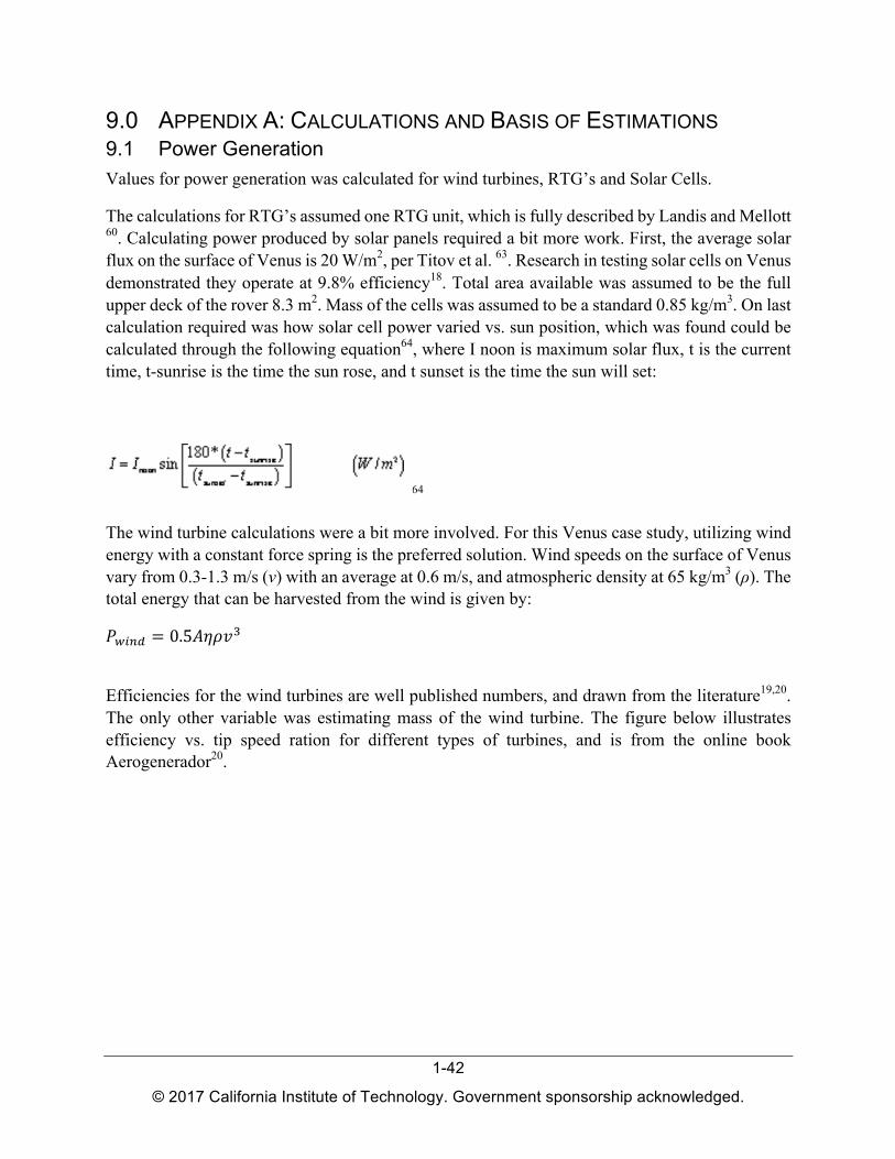
9.0 APPENDIX A: CALCULATIONS AND BASIS OF ESTIMATIONS 9.1 Power Generation Values for power generation was calculated for wind turbines, RTG’s and Solar Cells.
The calculations for RTG’s assumed one RTG unit, which is fully described by Landis and Mellott 60 . Calculating power produced by solar panels required a bit more work. First, the average solar flux on the surface of Venus is 20 W/m2 , per Titov et al. 63 . Research in testing solar cells on Venus demonstrated they operate at 9.8% efficiency18 . Total area available was assumed to be the full upper deck of the rover 8.3 m2 . Mass of the cells was assumed to be a standard 0.85 kg/m3 . On last calculation required was how solar cell power varied vs. sun position, which was found could be calculated through the following equation64 , where I noon is maximum solar flux, t is the current time, t-sunrise is the time the sun rose, and t sunset is the time the sun will set:
64
The wind turbine calculations were a bit more involved. For this Venus case study, utilizing wind energy with a constant force spring is the preferred solution. Wind speeds on the surface of Venus vary from 0.3-1.3 m/s (v) with an average at 0.6 m/s, and atmospheric density at 65 kg/m3 (ρ). The total energy that can be harvested from the wind is given by:
Pwind = 0.5Aηρv3
Efficiencies for the wind turbines are well published numbers, and drawn from the literature19,20 . The only other variable was estimating mass of the wind turbine. The figure below illustrates efficiency vs. tip speed ration for different types of turbines, and is from the online book Aerogenerador20 .
1-42
© 2017 California Institute of Technology. Government sponsorship acknowledged.

One of the more challenging aspects was computing mass for the wind turbine. For the Savonius, a grass roots CAD estimate was used. For the multi-blade turbines, equations to calculate wind turbine mass from diameter have already been established57 .
9.2 Power Estimation List (PEL) The power estimation to understand power consumption of the rover was divided into three different areas, instruments, locomotion, and signaling.
To compute power consumption for instruments, the data from the Venus Flagship Mission2
instruments was used, as it included sample collection to study geology.
For power required to drive the rover, the following, will known equation for drag on a moving vehicle was used.
1-43
© 2017 California Institute of Technology. Government sponsorship acknowledged.

It was assumed the rover would be driving into a 0.6 m/s head wind, at 0.1 m/s. CR was estimated to be 0.045 for tracks driving on hard soil65 (it would increase just slightly to 0.06 for wheels on hard soil). CD for a blunt body is 0.8 and frontal area of the rover was 5 m2 .
For the spinning disks for the signaling system, the second part of the equation above FD = 0.5*roe*cDAV2 was used, but converted into a rotation coordinate system and then integrated over radius to account for the spinning disk (which has a high velocity on the outside, and low velocity at the center). CD for a flat plate is 0.005. It was assumed atmospheric drag would by the primary power consumption of the spinning disks for signaling.
9.3 Power Storage The power density of various storage systems were found through existing publications. Energy densities for batteries compatible with Venus are noted by Landis and Harrison21 . Flywheels66 and compressed air systems67 have been documented. The articles referenced especially compare theoretical maximums to actual maximums. Energy stored in a gravity tower is just the potential energy of gravitation acceleration multiplied by height.
Maximum power in a spring is determined by the following equation68 :
0.5 (τmax)2 /(Yρ)
Where τmax is the yield strength and Y is the Young’s Modulus. All calculated values were discounted by 80% to ensure there was some margin of safety between the springs yield strength at working load. Data sheets were used for both steel (metal)69 and composite springs70 .
10.0 APPENDIX B: ADDITIONAL CONTRIBUTORS The authors give a special thanks to the following individuals, who provided advices or participated in the A-team study:
At JPL: Jeff Hall, Scott Hensley, Simone Tanelli, Jan Martin, Mike Pauken, Bruce Banerdt, Rosaly Lopes, Laura Kerber, James Cutts, Brian Wilcox, Arbi Karepetian, Brett Kennedy, Kim Aaron, Douglas Hofmann, Kevin Baines, Sue Schmekar, Yuki Maruyama, Mohammad Mojarradi
Other: Theo Jansen (Strandbeest), Kyle Colton (Planet Labs), Nathanael Miller (LaRC), Charlie Manion (Oregon State), Ofir Atia (Art Center), Lori Nishikawa (Art Cener)
1-44
© 2017 California Institute of Technology. Government sponsorship acknowledged.