automation in forming processes
TRANSCRIPT
State- of- the-A rt
Automation in Forming Processes
Dr. W. R o d d e c k * Ruhr-Universitdt Bochum, Lehrstuhl ffir Produktionssysteme, 4630 Bochum, Federal Republic of Germany
Whereas the extent of automation in plants relative cut- ting machine tools is rather large, automation with respect to forming machines is still rather limited. Due to the large number of varying parameters for formed materials, an automation tool of high flexibility is required. The variety of currently available microcomputers offers powerful such automation tools. The present paper surveys some of the forming processes that have become automated in the past few years, and others that are to be automated in the future.
Keywords: Forming processes, automation, plate bend- ing, open-loop controller, NC, forming machines, spinning
1. Introduction
The initial step in automating forming processes
today is the attachment of an open-loop controller
to the forming machine, without provisions for any
feedback of actual process parameters. So, if the
attributes of the formed material are varying, the
forming process cannot be adjusted to the new con- ditions. Examples of such varying attributes are:
spring rate of metals in cold forming processes, and
temperature in hot forming processes.
The quality of the product is highly dependent on
the know-how of the operator of the forming machine. Different approaches have been made to facilitate controlling the forming process in order to
reduce the responsibility of the operator, as well as to enhance the quality and the dimensional accuracy of
the product. Examples of different automation con- cepts are discussed in the following sections.
Dr. W. Roddeck received his M.S. degree in Mechanical Engineering in 1974 from Ruhr University at Bochum. He earned his Ph.D. at the same university in 1977, at the Insti- tute of Automation Technology with a work in Switching Theory. While at the Institute, Dr. Roddeck was engaged with several automation problems in the area of forming pro- cesses.
* Current Mailing Address: Fa. Lorenz Maschinenfabrik AG, Lorenzstrasse 2-4, D-7505 Ettlingen, F.R. Germany.
© North-Holland Publishing Company Computer in Industry 1 (1979) 111-116
2. NC-Strategies
Well-known NC-strategies for cutting machine
tools are often adapted to forming processes. For
example, in a coM forming process, cup-profiled parts are spun out of round sheets [1]. This technology works with a spinning roll which chases the round
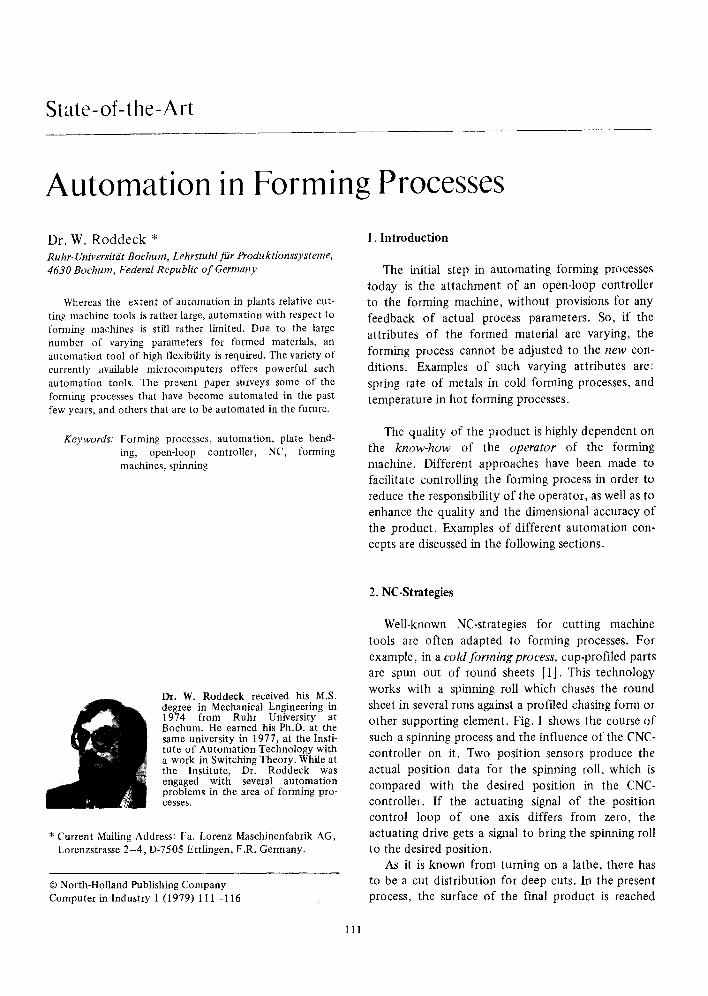
sheet in several runs against a profiled chasing form or other supporting element. Fig. 1 shows the course of
such a spinning process and the influence of the CNC- controller on it. Two position sensors produce the
actual position data for the spinning roll, which is
compared with the desired position in the CNC- controller. | f the actuating signal of the position control loop of one axis differs from zero, the actuating drive gets a signal to bring the spinning roll to the desired position.
As it is known from turning on a lathe, there has to be a cut distribution for deep cuts. In the present process, the surface of the final product is reached
111
112 State-of-the-Art
r---- 3 clipping \y /~" ,/
J ~ toot path z
, ~'~ ~ ; k ~ s p i n n i n g X
, ~, _ f i r II I
I * I
II~round sheet I
I
I j I I
J I
paper tape reader
c o n t r o l l e r i
I instantaneous values
I
I [[ p o s i t i o n I t
c p o
[switchin~ infor- mation
~ set values
c o n t r o l l e r
adapter and functional controller I 1
adjusting signals i
switching signals . . . . . . _j
Fig. 1. A spinning machine and controller.
from the base sizes by several passages of the spinning roll. The CNC gets the information about the tool path numerically either from a keyboard or from a paper tape reader. The CNC-controller consists of several microprocessors which intercommunicate onto the same storage. They all have specific jobs like creating position data, interpolation of the tool path, adaption between CNC-controller and forming machine, etc. So one gets a modular concept in soft- ware and hardware, and by this, it is quite easy to adapt such a CNC-controller to other forming machines.
Other problems in the forming processes can even
be solved by adding additional microprocessors for special operations. The latest developement in this area is to install an algorithm in the CNC which generates the position data for the tool path auto- matically if a cut distribution in the spinning process is necessary.
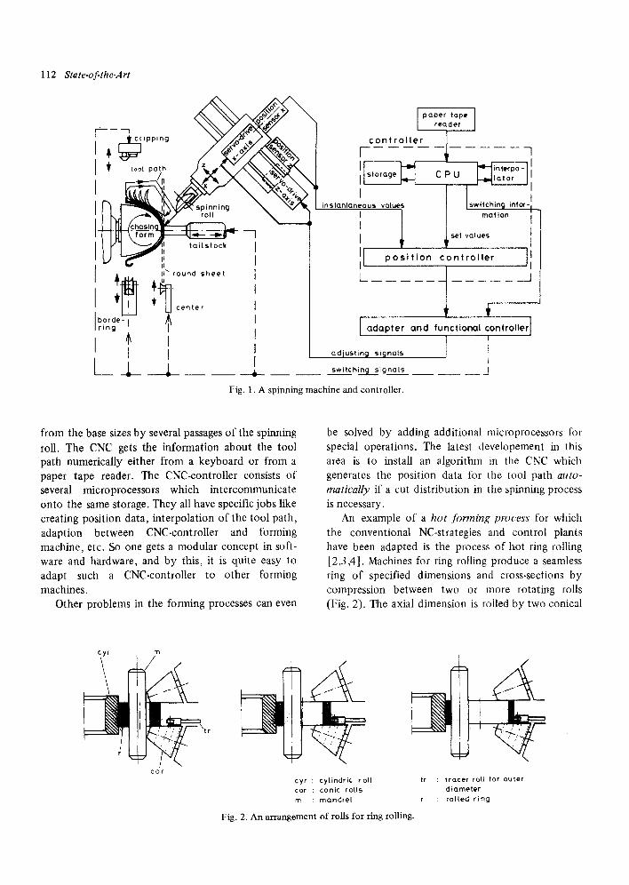
An example of a hot forming process for which the conventional NC-strategies and control plants have been adapted is the process of hot ring rolling [2,3,4]. Machines for ring rolling produce a seamless ring of specified dimensions and cross-sections by compression between two or more rotating rolls (Fig. 2). The axial dimension is rolled by two conical
cyr
I
m
~ \ t r
c o r
tr
r
c y r : c y l i n d r i c r o l l : t r a c e r r o t l f o r o u t e r
c a r : c o n i c r o l l s d i a m e t e r
m : m a n d r e l : r o l l e d r i n g
Fig. 2. An arrangement of rolls for ring rolling.
rolls and the radial dimension by a cylindric or pro- filed roll.
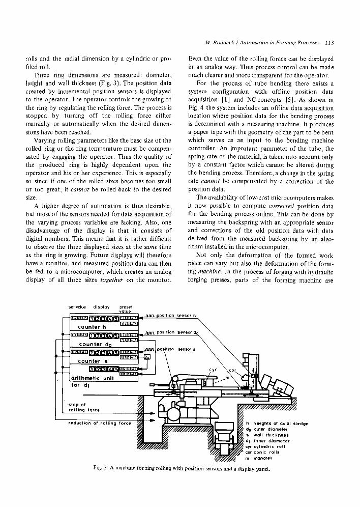
Three ring dimensions are measured: diameter, height and wall thickness (Fig. 3). The position data created by incremental position sensors is displayed to the operator. The operator controls the growing of the ring by regulating the rolling force. The process is stopped by turning off the rolling force either manually or automatically when the desired dimen- sions have been reached.
Varying rolling parameters like the base size of the rolled ring or the ring temperature must be compen- sated by engaging the operator. Thus the quality of the produced ring is highly dependent upon the operator and his or her experience. This is especially so since if one of the rolled sizes becomes too small or too great, it cannot be rolled back to the desired size.
A higher degree of automation is thus desirable, but most of the sensors needed for data acquisition of the varying process variables are lacking. Also, one disadvantage of the display is that it consists of digital numbers. This means that it is rather difficult to observe the three displayed sizes at the same time as the ring is growing. Future displays will therefore have a monitor, and measured position data can then be fed to a microcomputer, which creates an analog display of all three sizes together on the monitor.
14/. Roddeck / Autornation in bbrming Processes 113
Even the value of the rolling forces can be displayed in an analog way. Thus process control can be made much clearer and more transparent for the operator.
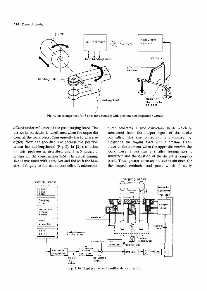
For the process of tube bending there exists a system configuration with offline position data acquisition [1] and NC-concepts [5]. As shown in Fig. 4 the system includes an offline data acquisition location where position data for the bending process is determined with a measuring machine. It produces a paper tape with the geometry of the part to be bent which serves as an input to the bending machine controller. An important parameter of the tube, the spring rate of the material, is taken into account only by a constant factor which cannot be altered during the bending process. Therefore, a change in the spring rate cannot be compensated by a correction of the position data.
The availability of low-cost microcomputers makes it now possible to compute corrected position data for the bending process online. This can be done by measuring the backspring with an appropriate sensor and corrections of the old position data with data derived from the measured backspring by an algo- rithm installed in the microcomputer.
Not only the deformation of the formed work piece can vary but also the deformation of the form- ing machine. In the process of forging with hydraulic forging presses, parts of the forming machine are
set value d isplay preset value
I " 1 " ~ t " 1 " ~ I ' ~ ' 1 P ' 4 ' ~ ~ JIJU1. position sensor h
counter Jl, J J~.A~L~ '-~-'~-'~ ~ h ~ L 9 ~ T l ~ - n l ~ ' l ~ l ~ J ~ J ~ J . . . . . -- J1J1J'L position Sensor d ~ ~
c o u n t e r dg ~ ~ o ~ n sensor s
counter s
(arithmetiCfor di unit . J ~ _ ~
stop of rolling force
N2 2t! N ro|Jing force heights axial ~ Jed(~ reduction o, ~/~ v ~ . of
7 / / / ~ L ~ J ~ ' ~ d i inner diameter ~ ~ cyr cylindric rol l
~ " m mandre I
Fig. 3. A machine for ring rolling with position sensors and a display panel.
114 State-of-the-Art
clamp
~ Neasur,ng I / J" ~ NC-Controler r'°~ ([" S stem
( \ . " -_ -k~" ~ ] !
. \ 1; 0o,,*,on,o,o' i ,o,,,oo,o0ox ,
/ Fig. 4. An arrangement for 3-axes tube bending with position data acquisition offline,
dilated under influence of the great forging force. The die set in particular is lengthened when the upper die touches the work piece. Consequently the forging size differs from the specified size because the position sensor has not lengthened (Fig. 5). In [3] a solution of this problem is described and Fig. 5 shows a scheme of the construction used. The actual forging size is measured with a resolver and fed with the base size of forging to the stroke controller. A microcom-
puter generates a size correction signal which is subtracted from the output signal of the stroke controller. The size correction is computed b y measuring the forging force with a pressure trans- ducer at the moment when the upper die touches the work piece. From this a smaller forging size is simulated and the dilation of the die set is compen- sated. Thus, greater accuracy to size is obtained for the forged products, and parts which formerly
control panel 7 I upper I cusp I point
I[ forging I s i ze
I reduct ion II s t roke I L.speed
,I,°°, I I correction
zero 1 instantaneous p o i n t stroke value
i set value acquisition J / Icontr
stroke set value
forging press
r e s o t v e r / I I I ~ IT-- l l ~---n---" I t
~ I contro,.k II ~ ~ ! \ ~ ~ f ° r ~ T II
_______: .~..pr.sure 11 II correctio.__lmicro- L,___ ~ ,ransOmer IJ JJ
~ _ I computer forging force
actuating signal
Fig. 5. NC forging press with position data correction.
couldn't be forged on a press, can now be formed with this technology.
3. Open-Loop Concepts
Examples of other forming processes in which the backspring of the formed material must be taken into account in order to obtain good results are edging and bending of plates. Plate bending machines with three rolls for bending of heavy plates are of especially great interest today [6]. These machines are primarily used in the manufacture of boilers and reactor vessels. Heavy-plate forming (in the past, the exclusive preserve of forging pressess) can now be carried out more efficiently, more accurately, and more rapidly on plate bending machines. A great disadvantage of this free forming process is that the actual diameter of the bent plate cannot be measured during the bending process. The quality of the product depends on the bending know-how of the operator. Measure- ment must be made with the bending rolls stopped, by placing a templet against the bent plate.
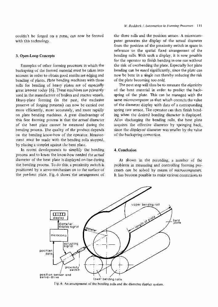
In recent developments to simplify the bending process and to lower the know-how needed the actual diameter of the bent plate is displayed on-line during the bending process. To do this, a proximity switch is positioned by a servo-mechanism on to the surface of the pre-bent plate. Fig. 6 shows the arrangement of
14/. Roddeck / Automation in Forming Processes 115
the three rolls and the position sensor. A microcom- puter generates the display of the actual diameter from the position of the proximity switch in space in reference to the spatial fixed arrangement of the bending rolls. With such a display, it is now possible for the operator to finish bending in one run without the risk of overbending the plate. Especially hot plate bending can be eased significantly, since the plate can now be bent in a single run thereby reducing the risk of the plate becoming too cold.
The next step will thus be to measure the elasticity of the bent material in order to predict the back- spring of the plate. This can be managed with the same microcomputer as that which corrects the value of the diameter display with data of a corresponding spring rate sensor. The operator can then finish bend- ing when the desired bending diameter is displayed. After discharging the bending rolls, the bent plate acquires the effective diameter by springing back, since the displayed diameter was smaller by the value of the backspring correction.
4. Conclusion
As shown in the preceding, a number of the problems in measuring and controlling forming pro- cesses can be solved by means of microcomputers. It has become possible to make various corrections to
bent plate
positi~ da
posihc servoL~, , ,~
lower bending rol ls
Fig. 6. An arrangement of the bending rolls and the diameter display system.
116 State-of-the.Art
numerical position data using data from sensors for the varying system parameters. This is due to the high flexibility of the microcomputer when used as a controller and to its arithmetic qualities. Naturally, the different NC-strategies well known from the field of cutting machine tools, can be realized for forming processes as well. Parts which could only be shaped by cutting processes in the past can now be shaped by forming processes, since the accuracy of these processes has increased significantly. This evolution is highly desirable because material consumption in forming processes is much less than that with cutting processes. Increasing the accuracy of forming processes can even make fashioning formed parts with cutting processes unnecessary.
References
[1] AutorenkoUektiv, Neuere Steuerungskonzepte zur Pro- duktivit~/tssteigerung, Industrie Anzeiger Bd. 100, Nr. 68, August 1978, pp. 86-109.
[2] W. Massberg, Steuern und Regeln beim Walzen ring- f6rmiger Werkstiicke, wt-Z. Ind. Fert. 61 (1971) pp. 346- 351.
[3] Herold, Massberg, Stute, Die numerische Steuerung in der Fertigungstechnik, VDI-Veflag Dtisseldorf 1971.
[4] J.T. Winship, Fundamentals of Forging, American Machinist, Vol. 122, No. 7, July 1978, 99-122.
[5] P. R6ssel and W. VoUrath, Numerische Steuerungen for Rohrbiegemaschinen, Siemens-Z. (1970) Nr. 44, Beiheft Numerisehe Steuerungen, S. 100.
[6]W. Klein, Entwicklung bei Blechrundbiegemaschinen Industrie-Anzeiger Bd. 100 (1978) Nr. 32, p. 836-39.