automation - wegecatalog.weg.net/files/wegnet/weg-cwm-contactors-50070163-brochur… · automation...
TRANSCRIPT

Motors | Automation | Energy | Transmission & Distribution | Coatings
Automation
Contactors - CWM Line

www.weg.net
Contactores Compactos CWC02

Sumary
Presentation 4
Reversing Starters
Spare Parts
16
18
Star-Delta Starters
Technical Data
17
19
Dimensions (mm) 39
5
9
10
11
12
13
Contactors - CWM Line
Accessories Overview
Three-Pole Contactors from 9 up to 250 A (AC-3) - AC Coil
Three-Pole Contactors from 40 up to 105 A (AC-3) - DC Coil
Three-Pole Contactors from 112 up to 800 A (AC-3) - Coil with Electronic Module AC/DC
Four-Pole Contactors - AC Coil or Coil with Electronic Module AC/DC
Accessories

CWM Contactors - Presentation
The CWM general-purpose contactor line has been designed taking into consideration industrial duty and reliability.
Rated for inductive loads up to 800 A or 440 kW @ 380/400 V, WEG can offer the most suitable contactor for your application.
CWM contactors allow total panel space optimization, with only a few compact frame sizes from 4 to 440 kW @ 400/415 V. Reducing inventory is simple with CWM common accessories. For example, side-mounted auxiliary contact blocks are the same from 9 to 300 A (AC-3) @ 440 V.
Designed for extended mechanical and electrical life, dependable switching in even the most heavy-duty applications can be achieved. No matter how demanding the application, all WEG contactors are tested and approved to be used under Type 1 and Type 2 short-circuit coordination.Ensuring global acceptance, all components conform to UL 508 (USA and Canada), IEC 60947 and CE.
All WEG contactors are manufactured to assure the highest quality manufacturing processes and component materials.
This way, WEG offers reliable solutions for low-voltage applications in electric panel assemblers, OEMs, distributors and end users.
www.weg.net
4 Contactors - CWM Line
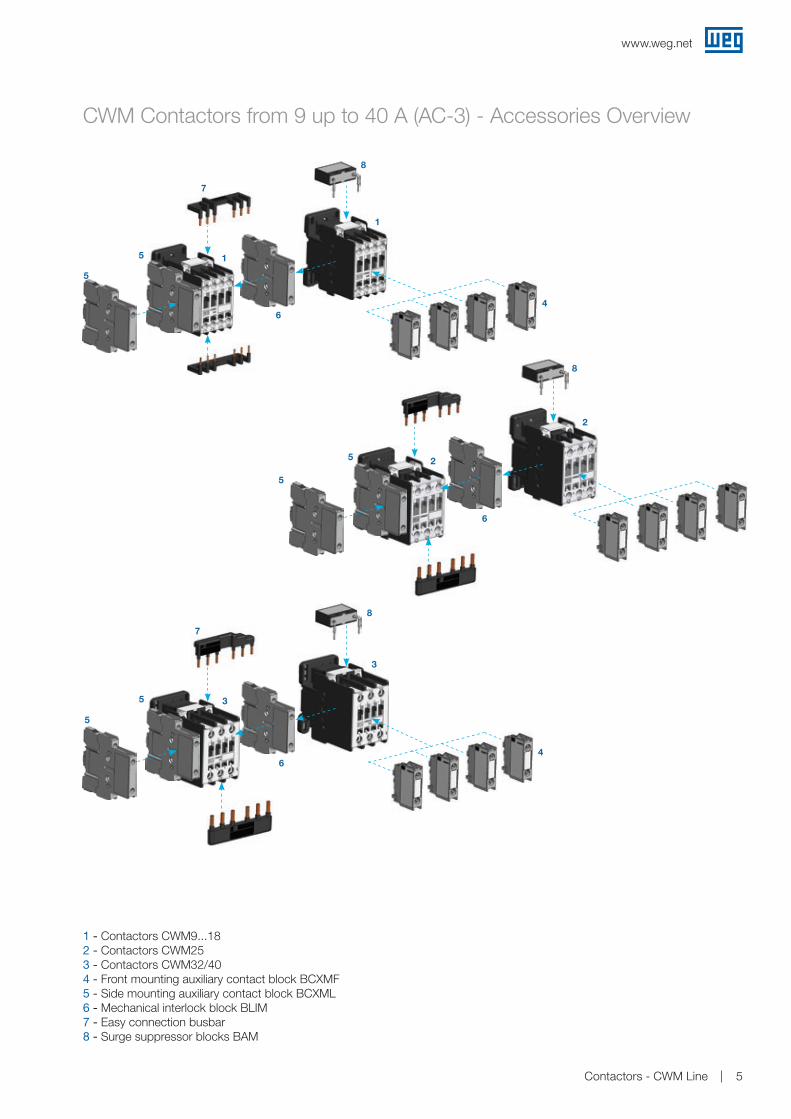
CWM Contactors from 9 up to 40 A (AC-3) - Accessories Overview
5
5
5
5
5
5
7
7
6
6
6
1
1
2
2
3
3
4
4
8
8
8
1 - Contactors CWM9...182 - Contactors CWM253 - Contactors CWM32/404 - Front mounting auxiliary contact block BCXMF5 - Side mounting auxiliary contact block BCXML6 - Mechanical interlock block BLIM7 - Easy connection busbar 8 - Surge suppressor blocks BAM
7
www.weg.net
5Contactors - CWM Line

CWM Contactors from 50 up to 105 A (AC-3) - Accessories Overview
1
1
2
2
3
3
7
7
6
6
5
5
4
4
4
4
1 - Contactors CWM50...802 - Contactors CWM95/1053 - Front mounting auxiliary contact block BCXMF4 - Side mounting auxiliary contact block BCXML5 - Mechanical interlock block BLIM6 - Easy connection busbar 7 - Surge suppressor blocks BAM
www.weg.net
6 Contactors - CWM Line

CWM Contactors from 112 up to 300 A (AC-3) - Accessories Overview
1 - Contactors CWM112/1502 - Contactors CWM1803 - Contactors CWM250/3004 - Side mounting auxiliary contact block BCXML5 - Mechanical interlock BLIM112-3006 - Surge suppressor block BAMV
7 - Terminal cover BMP CWM1508 - Terminal cover BMP CWM1809 - Terminal cover BMP CWM30010 - TB150 terminal block for CWM112-15011 - TB180 terminal block for CWM18012 - TB300 terminal block for CWM250-300
3
5
3
8
8
2
5
4
2
6
4
5
7
7
1
1
11
11
10
10
9
9
12
12
4
4
4
4
6
www.weg.net
7Contactors - CWM Line

CWM Contactors from 400 up to 800 A (AC-3) - Accessories Overview
5
3
4
6
1
1
8
1 - Contactor CWM4002 - Contactors CWM500...8003 - Auxiliary contacts block BCXMRL CWM8004 - Mechanical interlock BLIM CWM4005 - Mechanical interlock BLIM CWM8006 - Terminal cover BMP CWM4007 - Terminal cover BMP CWM8008 - Lugs BMJ CWM4009 - Lugs BMJ CWM800
3
2
2 7
9
www.weg.net
8 Contactors - CWM Line
Replace “♦” with the Appropriate Coil Voltage Code2)
Ratedoperational
currentIe AC-3
(Ue ≤ 440 V)
A
Conv.thermalcurrentIth = Ie AC-1
A
Max. rated operational power of three-phase motors 50/60 Hz1)
Auxiliary contactsper contactor
Auxiliary contact blocksseparately delivered
Reference code to complete with
voltage code
Weight
kg
220 V230 V
kW / HP
380 V
kW / HP
400 V415 V
kW / HP
440 V
kW / HP
500 V
kW / HP
660 V690 V
kW / HP4
3
2
1
BCXMF10
NO
BCXMF01
NCNO NC
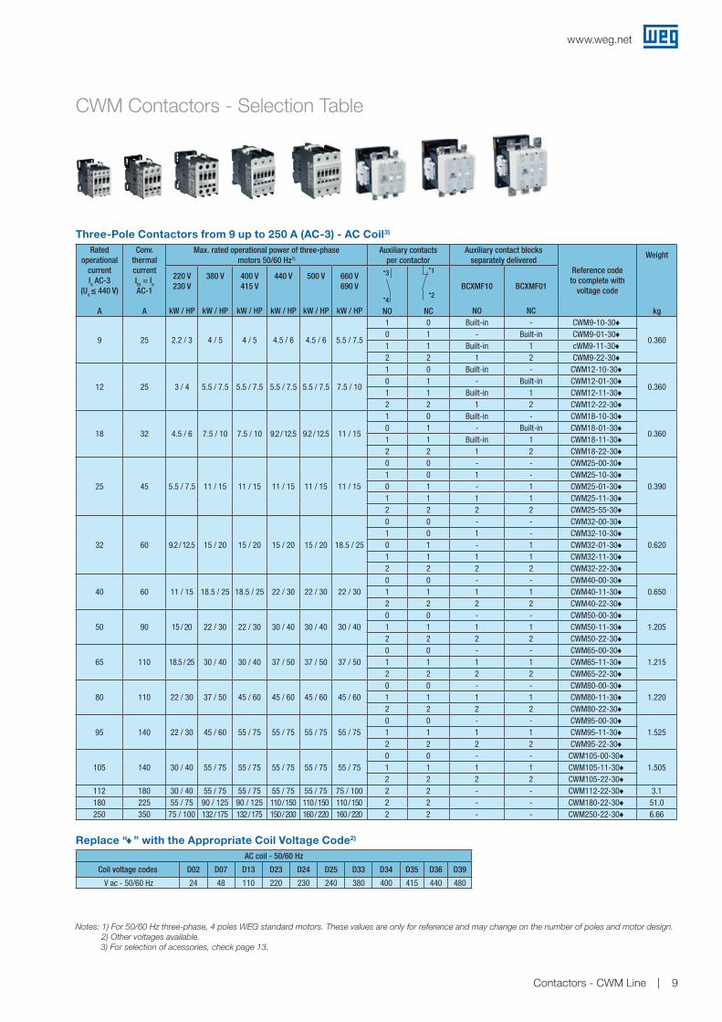
9 25 2.2 / 3 4 / 5 4 / 5 4.5 / 6 4.5 / 6 5.5 / 7.5
1 0 Built-in - CWM9-10-30♦
0.3600 1 - Built-in CWM9-01-30♦1 1 Built-in 1 cWM9-11-30♦2 2 1 2 CWM9-22-30♦
12 25 3 / 4 5.5 / 7.5 5.5 / 7.5 5.5 / 7.5 5.5 / 7.5 7.5 / 10
1 0 Built-in - CWM12-10-30♦
0.3600 1 - Built-in CWM12-01-30♦1 1 Built-in 1 CWM12-11-30♦2 2 1 2 CWM12-22-30♦
18 32 4.5 / 6 7.5 / 10 7.5 / 10 9.2 / 12.5 9.2 / 12.5 11 / 15
1 0 Built-in - CWM18-10-30♦
0.3600 1 - Built-in CWM18-01-30♦1 1 Built-in 1 CWM18-11-30♦2 2 1 2 CWM18-22-30♦
25 45 5.5 / 7.5 11 / 15 11 / 15 11 / 15 11 / 15 11 / 15
0 0 - - CWM25-00-30♦
0.3901 0 1 - CWM25-10-30♦0 1 - 1 CWM25-01-30♦1 1 1 1 CWM25-11-30♦2 2 2 2 CWM25-55-30♦
32 60 9.2 / 12.5 15 / 20 15 / 20 15 / 20 15 / 20 18.5 / 25
0 0 - - CWM32-00-30♦
0.6201 0 1 - CWM32-10-30♦0 1 - 1 CWM32-01-30♦1 1 1 1 CWM32-11-30♦2 2 2 2 CWM32-22-30♦
40 60 11 / 15 18.5 / 25 18.5 / 25 22 / 30 22 / 30 22 / 300 0 - - CWM40-00-30♦
0.6501 1 1 1 CWM40-11-30♦2 2 2 2 CWM40-22-30♦
50 90 15 / 20 22 / 30 22 / 30 30 / 40 30 / 40 30 / 400 0 - - CWM50-00-30♦
1.2051 1 1 1 CWM50-11-30♦2 2 2 2 CWM50-22-30♦
65 110 18.5 / 25 30 / 40 30 / 40 37 / 50 37 / 50 37 / 500 0 - - CWM65-00-30♦
1.2151 1 1 1 CWM65-11-30♦2 2 2 2 CWM65-22-30♦
80 110 22 / 30 37 / 50 45 / 60 45 / 60 45 / 60 45 / 600 0 - - CWM80-00-30♦
1.2201 1 1 1 CWM80-11-30♦2 2 2 2 CWM80-22-30♦
95 140 22 / 30 45 / 60 55 / 75 55 / 75 55 / 75 55 / 750 0 - - CWM95-00-30♦
1.5251 1 1 1 CWM95-11-30♦2 2 2 2 CWM95-22-30♦
105 140 30 / 40 55 / 75 55 / 75 55 / 75 55 / 75 55 / 750 0 - - CWM105-00-30♦
1.5051 1 1 1 CWM105-11-30♦2 2 2 2 CWM105-22-30♦
112 180 30 / 40 55 / 75 55 / 75 55 / 75 55 / 75 75 / 100 2 2 - - CWM112-22-30♦ 3.1180 225 55 / 75 90 / 125 90 / 125 110 / 150 110 / 150 110 / 150 2 2 - - CWM180-22-30♦ 51.0250 350 75 / 100 132 / 175 132 / 175 150 / 200 160 / 220 160 / 220 2 2 - - CWM250-22-30♦ 6.66
Notes: 1) For 50/60 Hz three-phase, 4 poles WEG standard motors. These values are only for reference and may change on the number of poles and motor design. 2) Other voltages available. 3) For selection of acessories, check page 13.
Three-Pole Contactors from 9 up to 250 A (AC-3) - AC Coil3)
AC coil - 50/60 Hz
Coil voltage codes D02 D07 D13 D23 D24 D25 D33 D34 D35 D36 D39
V ac - 50/60 Hz 24 48 110 220 230 240 380 400 415 440 480
CWM Contactors - Selection Table
www.weg.net
9Contactors - CWM Line
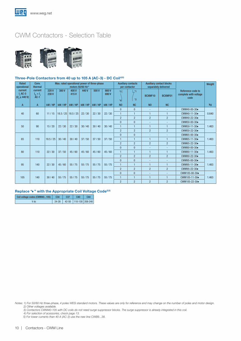
Notes: 1) For 50/60 Hz three-phase, 4 poles WEG standard motors. These values are only for reference and may change on the number of poles and motor design. 2) Other voltages available. 3) Contactors CWM40-105 with DC coils do not need surge suppressor blocks. The surge suppressor is already integrated in this coil. 4) For selection of acessories, check page 13. 5) For lower currents than 40 A (AC-3) use the new line CWB9...38.
Replace “♦” with the Appropriate Coil Voltage Code2)3) Coil voltage codes (CWM40...105) C34 C37 C40 C44
V dc 24-28 42-50 110-130 208-240
Ratedoperational
currentIe AC-3
(Ue ≤ 440 V)
Conv.thermalcurrentIth = Ie AC-1
Max. rated operational power of three-phase motors 50/60 Hz1)
Auxiliary contactsper contactor
Auxiliary contact blocksseparately delivered
Reference code to complete with voltage
code
Weight
kg
220 V230 V
380 V 400 V415 V
440 V 500 V 660 V690 V
4
3
2
1
BCXMF10 BCXMF01
A A kW / HP kW / HP kW / HP kW / HP kW / HP kW / HP NO NC NO NC
40 60 11 / 15 18.5 / 25 18.5 / 25 22 / 30 22 / 30 22 / 30
0 0 - - CWM40-00-30♦0.6401 1 1 1 CWM40-11-30♦
2 2 2 2 CWM40-22-30♦
50 90 15 / 20 22 / 30 22 / 30 30 / 40 30 / 40 30 / 40
0 0 - - CWM50-00-30♦1.4631 1 1 1 CWM50-11-30♦
2 2 2 2 CWM50-22-30♦
65 110 18.5 / 25 30 / 40 30 / 40 37 / 50 37 / 50 37 / 50
0 0 - - CWM65-00-30♦1.4631 1 1 1 CWM65-11-30♦
2 2 2 2 CWM65-22-30♦
80 110 22 / 30 37 / 50 45 / 60 45 / 60 45 / 60 45 / 60
0 0 - - CWM80-00-30♦1.4631 1 1 1 CWM80-11-30♦
2 2 2 2 CWM80-22-30♦
95 140 22 / 30 45 / 60 55 / 75 55 / 75 55 / 75 55 / 75
0 0 - - CWM95-00-30♦1.4631 1 1 1 CWM95-11-30♦
2 2 2 2 CWM95-22-30♦
105 140 30 / 40 55 / 75 55 / 75 55 / 75 55 / 75 55 / 75
0 0 - - CWM105-00-30♦1.4631 1 1 1 CWM105-11-30♦
2 2 2 2 CWM105-22-30♦
Three-Pole Contactors from 40 up to 105 A (AC-3) - DC Coil4)5)
CWM Contactors - Selection Table
www.weg.net
10 Contactors - CWM Line
Rated operational current Ie AC-3
(Ue ≤ 440 V)
A
Conv. thermal currentIth = Ie AC-1
A
Max. rated operational power of three-phase motors 50/60 Hz1)
Auxiliary contactsper contactor (BCXML)
Reference code to complete with
voltage code
Weight
kg
220 V230 V
kW / HP
380 V
kW / HP
400 V415 V
kW / HP
440 V
kW / HP
500 V
kW / HP
690 V
kW / HP
4
3
2
1
NO NC
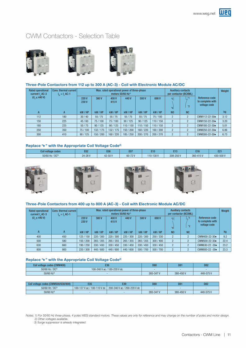
112 180 30 / 40 55 / 75 55 / 75 55 / 75 55 / 75 75 / 100 2 2 CWM112-22-30♦ 3.12
150 225 45 / 60 75 / 100 75 / 100 90 / 125 90 / 125 110 / 150 2 2 CWM150-22-30♦ 3.20
180 225 50 / 75 90 / 125 90 / 125 110 / 150 110 / 150 110 / 150 2 2 CWM180-22-30♦ 5.01
250 350 75 / 100 132 / 175 132 / 175 150 / 200 160 / 220 160 / 200 2 2 CWM250-22-30♦ 6.86
300 410 90 / 125 150 / 200 160 / 220 185 / 250 200 / 270 200 / 270 2 2 CWM300-22-30♦ 6.73
Coil voltage codes E02 E06 E07 E10 E13 E16 E21
50/60 Hz / DC3) 24-28 V 42-50 V 60-72 V 110-130 V 208-250 V 360-415 V 430-500 V
Replace “♦” with the Appropriate Coil Voltage Code2)
Rated operational current Ie AC-3
(Ue ≤ 440 V)
A
Conv. thermal current Ith = Ie AC-1
A
Max. rated operational power of three-phase motors 50/60 Hz1)
Auxiliary contactsper contactor (BCXML)
Reference code to complete with
voltage code
Weight
kg
220 V230 V
380 V 400 V415 V
440 V 500 V 690 V
4
3
2
1
kW / HP kW / HP kW / HP kW / HP kW / HP kW / HP NO NC
400 450 125 / 150 220 / 300 220 / 300 220 / 300 220 / 300 250 / 330 2 2 CWM400-22-30♦ 9.2
500 580 150 / 200 265 / 355 265 / 355 265 / 355 265 / 355 300 / 400 2 2 CWM500-22-30♦ 22.4
630 660 190 / 250 330 / 450 330 / 450 330 / 450 330 / 450 330 / 450 2 2 CWM630-22 -30♦ 23.2
800 900 220 / 300 440 / 600 440 / 600 440 / 600 500 / 700 500 / 700 2 2 CWM800-22 -30♦ 23.3
Three-Pole Contactors from 112 up to 300 A (AC-3) - Coil with Electronic Module AC/DC
Three-Pole Contactors from 400 up to 800 A (AC-3) - Coil with Electronic Module AC/DC
Replace “♦” with the Appropriate Coil Voltage Code2) Coil voltage codes (CWM400) E36 D80 D81 D82
50/60 Hz / DC3) 100-240 V ac / 100-220 V dc - - -50/60 Hz3) - 265-347 V 380-450 V 440-575 V
Coil voltage codes (CWM500/630/800) E35 E39 D80 D81 D8250/60 Hz / DC3) 100-127 V ac / 100-110 V dc 200-240 V ac / 200-220 V dc - - -
50/60 Hz3) - - 265-347 V 380-450 V 440-575 V
Notes: 1) For 50/60 Hz three-phase, 4 poles WEG standard motors. These values are only for reference and may change on the number of poles and motor design. 2) Other voltages available.
3) Surge suppressor is already integrated.
CWM Contactors - Selection Table
www.weg.net
11Contactors - CWM Line

CWM Contactors - Selection Table
Replace “♦” with the Appropriate Coil Voltage Code1)
Four-Pole Contactors from 420 up to 800 A AC-1 - Coil with Electronic Module AC/DC
AC coil - 50/60 Hz
Applicable for CWC07…CWC025 models
Coil voltage codes D02 D07 D13 D23 D24 D25 D33 D34 D35 D36 D39 V ac - 50/60 Hz 24 48 110 220 230 240 380 400 415 440 480
Four-Pole Contactors from 25 to 32 A (AC-1)
Conv. thermal current Ith (55ºC)
A
AC-1 current
A
AC-1 powerAuxiliary contacts per
contactor (BCXML)Reference code to complete with
voltage code
Weight
kg
220 V240 V
380 V400 V
500 V550 V
690 V4
3
2
1
kW kW kW kW NO NC
500 420 160 300 375 470 2 2 CWM400-22-40♦ 9.9
630 630 245 450 560 710 2 2 CWM500-22-40♦ 26.3
750 660 255 470 590 740 2 2 CWM630-22 -40♦ 26.3
900 800 310 570 710 900 2 2 CWM800-22 -40♦ 26.3
Ie = Ith(Ue ≤ 690 V)θ ≤ 55 °C
AC-1
A
Number of poles
Reference code to complete with
voltage code
Weight
kg4
3
NO2
1
NC
252 2 CWM9-00-22♦
0.3604 - CWM9-00-40♦
252 2 CWM12-00-22♦
0.3604 - CWM12-00-40♦
322 2 CWM18-00-22♦
0.3604 - CWM18-00-40♦
Replace “♦” with the Appropriate Coil Voltage Code2) Coil voltage codes (CWM400) E36 D80 D81 D82
50/60 Hz / DC3) 100-240 V ac / 100-220 V dc - - -50/60 Hz3) - 265-347 V 380-450 V 440-575 V
Coil voltage codes (CWM500/630/800) E35 E39 D80 D81 D8250/60 Hz / DC3) 100-127 V ac / 100-110 V dc 200-240 V ac / 200-220 V dc - - -
50/60 Hz3) - - 265-347 V 380-450 V 440-575 V
www.weg.net
12 Contactors - CWM Line
CWM Contactors - Accessories
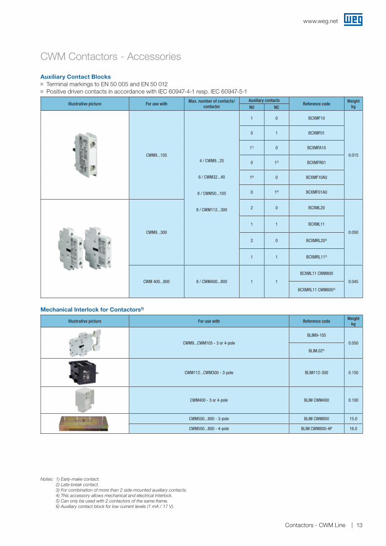
Auxiliary Contact Blocksg Terminal markings to EN 50 005 and EN 50 012g Positive driven contacts in accordance with IEC 60947-4-1 resp. IEC 60947-5-1
Mechanical Interlock for Contactors5)
Illustrative picture For use with Reference codeWeight
kg
CWM9...CWM105 - 3 or 4-pole
BLIM9-105
0.050
BLIM.024)
CWM112...CWM300 - 3-pole BLIM112-300 0.150
CWM400 - 3 or 4-pole BLIM CWM400 0.100
CWM500...800 - 3-pole BLIM CWM800 15.0
CWM500...800 - 4-pole BLIM CWM800-4P 16.0
Illustrative picture For use withMax. number of contacts/
contactorAuxiliary contacts
Reference codeWeight
kgNO NC
CWM9...1054 / CWM9...25
6 / CWM32...40
8 / CWM50...105
8 / CWM112...300
1 0 BCXMF10
0.015
0 1 BCXMF01
11) 0 BCXMFA10
0 12) BCXMFR01
16) 0 BCXMF10AU
0 16) BCXMF01AU
CWM9...300
2 0 BCXML20
0.050
1 1 BCXML11
2 0 BCXMRL203)
1 1 BCXMRL113)
CWM 400...800 8 / CWM400...800 1 1
BCXML11 CWM800
0.045
BCXMRL11 CWM8003)
Notes: 1) Early-make contact. 2) Late-break contact. 3) For combination of more than 2 side-mounted auxiliary contacts. 4) This accessory allows mechanical and electrical interlock. 5) Can only be used with 2 contactors of the same frame. 6) Auxiliary contact block for low current levels (1 mA / 17 V).
www.weg.net
13Contactors - CWM Line
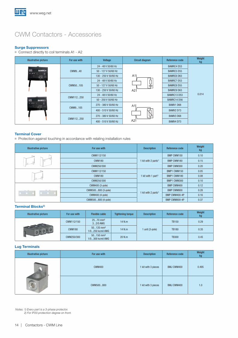
Illustrative picture For use with Flexible cable Tightening torque Description Reference codeWeight
kg
CWM112/15025...70 mm² 3...2/0 AWG
14 N.m
1 unit (3-pole)
TB150 0.29
CWM18050...120 mm²
1/0...250 kcmil AWG14 N.m TB180 0.35
CWM250/30050...150 mm²
1/0...300 kcmil AWG20 N.m TB300 0.45
Surge Suppressorsg Connect directly to coil terminals A1 - A2
Illustrative picture For use with Voltage Circuit diagram Reference codeWeight
kg
CWM9...40
24 - 48 V 50/60 Hz BAMRC4 D53
0.014
50 - 127 V 50/60 Hz BAMRC5 D55
130 - 250 V 50/60 Hz BAMRC6 D63
CWM50...105
24 - 48 V 50/60 Hz BAMRC7 D53
50 - 127 V 50/60 Hz BAMRC8 D55
130 - 250 V 50/60 Hz BAMRC9 D63
CWM112...25024 - 48 V 50/60 Hz BAMRC13 D53
50 - 250 V 50/60 Hz BAMRC14 D56
CWM9...105270 - 380 V 50/60 Hz BAMV1 D68
400 - 510 V 50/60 Hz BAMV2 D73
CWM112...250270 - 380 V 50/60 Hz BAMV3 D68
400 - 510 V 50/60 Hz BAMV4 D73
Terminal Coverg Protection against touching in accordance with relating installation rules
Illustrative picture For use with Description Reference codeWeight
kg
CWM400 1 kit with 3 pieces BMJ CWM400 0.495
CWM500...800 1 kit with 3 pieces BMJ CWM400 1.0
Lug Terminals
Illustrative picture For use with Description Reference codeWeight
kg
CWM112/150
1 kit with 2 parts1)
BMP CWM150 0.10
CWM180 BMP CWM180 0.15
CWM250/300 BMP CWM300 0.20
CWM112/150
1 kit with 1 part1)
BMP1 CWM150 0.05
CWM180 BMP1 CWM180 0.08
CWM250/300 BMP1 CWM300 0.10
CWM400 (3-pole)
1 kit with 2 parts1)
BMP CWM400 0.12
CWM500...800 (3-pole) BMP CWM800 0.28
CWM400 (4-pole) BMP CWM400-4P 0.16
CWM500...800 (4-pole) BMP CWM800-4P 0.37
Terminal Blocks2)
Notes: 1) Every part is a 3-phase protector. 2) For IP20 protection degree on front.
CWM Contactors - Accessories
www.weg.net
14 Contactors - CWM Line
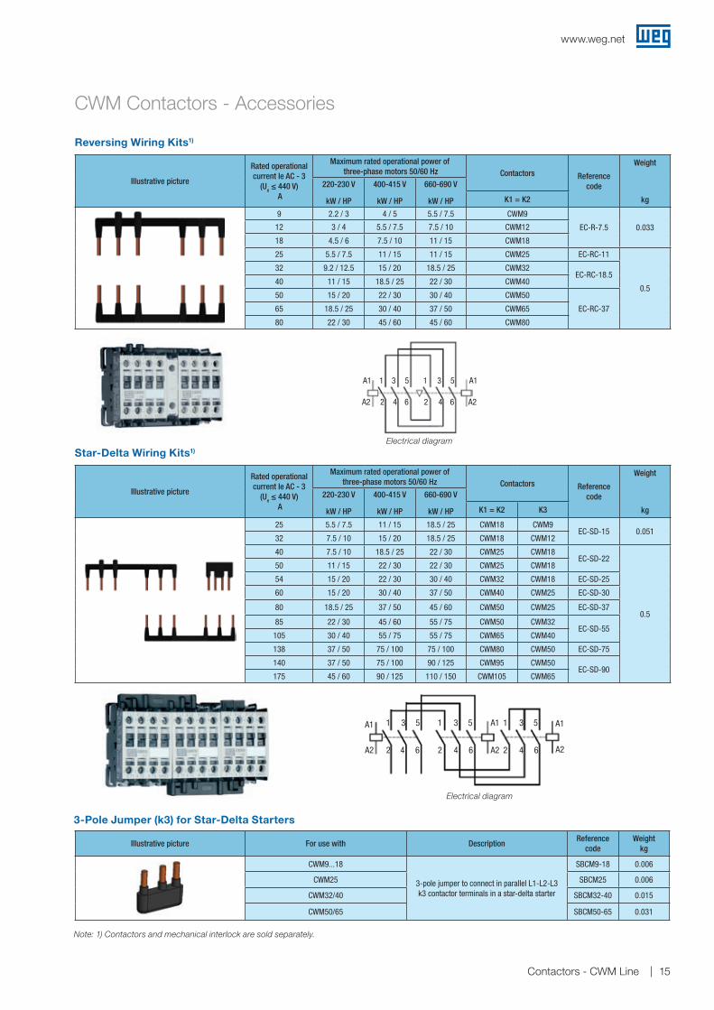
Reversing Wiring Kits1)
Illustrative picture
Rated operationalcurrent Ie AC - 3
(Ue ≤ 440 V) A
Maximum rated operational power of three-phase motors 50/60 Hz Contactors Reference
code
Weight
kg
220-230 V
kW / HP
400-415 V
kW / HP
660-690 V
kW / HP K1 = K2
9 2.2 / 3 4 / 5 5.5 / 7.5 CWM9
EC-R-7.5 0.03312 3 / 4 5.5 / 7.5 7.5 / 10 CWM12
18 4.5 / 6 7.5 / 10 11 / 15 CWM18
25 5.5 / 7.5 11 / 15 11 / 15 CWM25 EC-RC-11
0.5
32 9.2 / 12.5 15 / 20 18.5 / 25 CWM32EC-RC-18.5
40 11 / 15 18.5 / 25 22 / 30 CWM40
50 15 / 20 22 / 30 30 / 40 CWM50
EC-RC-3765 18.5 / 25 30 / 40 37 / 50 CWM65
80 22 / 30 45 / 60 45 / 60 CWM80
Star-Delta Wiring Kits1)
Illustrative picture
Rated operationalcurrent Ie AC - 3
(Ue ≤ 440 V) A
Maximum rated operational power of three-phase motors 50/60 Hz Contactors Reference
code
Weight
kg
220-230 V
kW / HP
400-415 V
kW / HP
660-690 V
kW / HP K1 = K2 K3
25 5.5 / 7.5 11 / 15 18.5 / 25 CWM18 CWM9EC-SD-15 0.051
32 7.5 / 10 15 / 20 18.5 / 25 CWM18 CWM12
40 7.5 / 10 18.5 / 25 22 / 30 CWM25 CWM18EC-SD-22
0.5
50 11 / 15 22 / 30 22 / 30 CWM25 CWM18
54 15 / 20 22 / 30 30 / 40 CWM32 CWM18 EC-SD-25
60 15 / 20 30 / 40 37 / 50 CWM40 CWM25 EC-SD-30
80 18.5 / 25 37 / 50 45 / 60 CWM50 CWM25 EC-SD-37
85 22 / 30 45 / 60 55 / 75 CWM50 CWM32EC-SD-55
105 30 / 40 55 / 75 55 / 75 CWM65 CWM40
138 37 / 50 75 / 100 75 / 100 CWM80 CWM50 EC-SD-75
140 37 / 50 75 / 100 90 / 125 CWM95 CWM50EC-SD-90
175 45 / 60 90 / 125 110 / 150 CWM105 CWM65
CWM Contactors - Accessories
2 2 24 4 4
5 5 5
6 6 6
1 1 13 3 3A1 A1 A1
A2 A2 A2
Note: 1) Contactors and mechanical interlock are sold separately.
Electrical diagram
A1A1 A1
A2 A22 24 4
5 5
6 6
1 13 3
Electrical diagram
3-Pole Jumper (k3) for Star-Delta Starters
Illustrative picture For use with DescriptionReference
codeWeight
kg
CWM9...18
3-pole jumper to connect in parallel L1-L2-L3 k3 contactor terminals in a star-delta starter
SBCM9-18 0.006
CWM25 SBCM25 0.006
CWM32/40 SBCM32-40 0.015
CWM50/65 SBCM50-65 0.031
www.weg.net
15Contactors - CWM Line

Individual Components for Reversing Starters
CWM Contactors - Reversing Starters
Reversing starters
Maximum rated operational power ofthree-phase motors 50/60 Hz
Individual components for reversing starters
ContactorK1
ContactorK2
Spare auxiliary contacts Mechanicalinterlock
Wiring kit220-230 VkW / HP
400 -415 VkW / HP
500 VkW / HP
660-690 VkW / HP Type Type K1 K2
2.2 / 3 4 / 5 4.5 / 6 5.5 / 7.5 CWM9-11 CWM9-11 - -
BLIM
9-10
5
EC-S
D...
3 / 4 5.5 / 7.5 5.5 / 7.5 7.5 / 10 CWM12-11 CWM12-11 - -
4.5 / 6 7.5 / 10 9.2 / 12.5 11 / 15 CWM18-11 CWM18-11 - -
5.5 / 7.5 11 / 15 11 / 15 11 / 15 CWM25-11 CWM25-11 - -
9.2 / 12.5 15 / 20 15 / 20 18.5 / 25 CWM32-11 CWM32-11 - -
11 / 15 18.5 / 25 22 / 30 22 / 30 CWM40-11 CWM40-11 - -
15 / 20 22 / 30 30 / 40 30 / 40 CWM50-11 CWM50-11 - -
18.5 / 25 30 / 40 37 / 50 37 / 50 CWM65-11 CWM65-11 - -
22 / 30 45 / 60 45 / 60 45 / 60 CWM80-11 CWM80-11 - -
22 / 30 55 / 75 55 / 75 55 / 75 CWM95-11 CWM95-11 - -
-
30 / 40 55 / 75 55 / 75 55 / 75 CWM105-11 CWM105-11 - -
30 / 40 55 / 75 55 / 75 75 / 100 CWM112-22 CWM112-22 1NO/1NC 1NO/1NC
BLIM
112-
300
45 / 60 75 / 100 90 / 125 110 / 150 CWM150-22 CWM150-22 1NO/1NC 1NO/1NC
55 / 75 90 / 125 110 / 150 110 / 150 CWM180-22 CWM180-22 1NO/1NC 1NO/1NC
75 / 100 132 / 175 160 / 220 160 / 220 CWM250-22 CWM250-22 1NO/1NC 1NO/1NC
90 / 125 160 / 220 200 / 270 200 / 270 CWM300-22 CWM300-22 1NO/1NC 1NO/1NC
www.weg.net
16 Contactors - CWM Line

Star-Delta Starters
Individual Components for Star-Delta Starters
Maximum rated operational power ofthree-phase motors 50/60 Hz
Individual components for star-delta starters
Main contactorK1
Delta contactorK2
Star contactorK3 Timer
Spare auxiliary contacts Wiring kit220-230 V
kW / HP400-415 VkW / HP
500 VkW / HP
660-690 VkW / HP Type Type Type K1 K2 K3
5.5 / 7.5 11 / 15 15 / 20 18.5 / 25 CWM18-10 + BCXMF10 CWM18-11 CWM9-11
RTW
-ET.
..
- - -
EC-S
D...
7.5 / 10 15 / 20 15 / 20 18.5 / 25 CWM18-10 + BCXMF10 CWM18-11 CWM12-11 - - -
7.5 / 10 18.5 / 25 22 / 30 22 / 30 CWM25-00 + 2 x BCXMF10 CWM25-11 CWM18-11 - - -
11 / 15 22 / 30 22 / 30 22 / 30 CWM25-00 + 2 x BCXMF10 CWM25-11 CWM18-11 - - -
15 / 20 30 / 40 37 / 50 37 / 50 CWM40-00 + 2 x BCXMF10 CWM40-11 CWM25-11 - - -
18.5 / 25 37 / 50 37 / 50 45 / 60 CWM50-00 + 2 x BCXMF10 CWM50-11 CWM25-11 - - -
22 / 30 45 / 60 45 / 60 55 / 75 CWM50-00 + 2 x BCXMF10 CWM50-11 CWM32-11 - - -
30 / 40 55 / 75 55 / 75 55 / 75 CWM65-00 + 2 x BCXMF10 CWM65-11 CWM40-11 - - -
37 / 50 75 / 100 75 / 100 90 / 125 CWM95-00 + 2 x BCXMF10 CWM95-11 CWM50-11 - - -
45 / 60 90 / 125 110 / 150 110 / 150 CWM105-00 + 2 x BCXMF10 CWM105-11 CWM65-11 - - -
55 / 75 110 / 150 110 / 150 132 / 175 CWM150-22 CWM150-22 CWM65-11 2NC 1NO/NC -
75 / 100 132 / 175 132 / 175 132 / 175 CWM180-22 CWM180-22 CWM80-11 2NC 1NO/NC -
90 / 125 160 / 220 160 / 220 200 / 300 CWM250-22 CWM250-22 CWM105-11 2NC 1NO/NC -
110 / 150 200 / 270 250 / 330 - CWM300-22 CWM300-22 CWM150-22 2NC 1NO/NC 1NO/NC
CWM Contactors - Star-Delta Starters
A: 0.58 x Ir, motor protection at star and delta positionB: 1 x Ir, only partial motor protecton at star positionC: 0.58 x Ir, motor not protected at star position
Star-Delta Starter
V2
U2
W2W1
V1
U1
K1
K1 K3
K3 K2
K2
www.weg.net
17Contactors - CWM Line
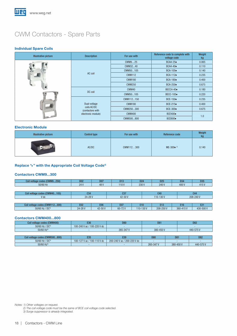
Illustrative picture Description For use withReference code to complete with
voltage codeWeight
kg
AC coil
CWM9....25 BCA4-25♦ 0.065
CWM32...40 BCA4-40♦ 0.110
CWM50...105 BCA-105♦ 0.140
CWM112 BCA-112♦ 0.235
CWM180 BCA-180♦ 0.400
CWM250 BCA-250♦ 0.675
DC coilCWM40 BECC4-40♦ 0.180
CWM50...105 BECC-105♦ 0.220
Dual-voltagecoils AC/DC
(contactors with electronic module)
CWM112...150 BCE-150♦ 0.235
CWM180 BCE-215♦ 0.400
CWM250...300 BCE-300♦ 0.675
CWM400 BCE400♦1.0
CWM500...800 BCE800♦
Individual Spare Coils
Coil voltage codes (CWM40...105) C34 C37 C40 C44 V dc 24-28 V 42-50 V 110-130 V 208-240 V
Replace “♦” with the Appropriate Coil Voltage Code1)
Coil voltage codes (CWM9...250) D02 D07 D13 D24 D25 D34 D3550/60 Hz 24 V 48 V 110 V 230 V 240 V 400 V 415 V
Contactors CWM9...300
Illustrative picture Control type For use with Reference codeWeight
kg
AC/DC CWM112…300 ME-300♦2) 0.140
Electronic Module
Coil voltage codes (CWM112...300) E02 E06 E07 E10 E13 E16 E2150/60 Hz / DC3) 24-28 V 42-50 V 60-72 V 110-130 V 208-250 V 360-415 V 430-500 V
Notes: 1) Other voltages on request.2) The coil voltage code must be the same of BCE coil voltage code selected.3) Surge suppressor is already integrated.
CWM Contactors - Spare Parts
Coil voltage codes (CWM400) E36 D80 D81 D8250/60 Hz / DC3) 100-240 V ac / 100-220 V dc - - -
50/60 Hz3) - 265-347 V 380-450 V 440-575 V
Coil voltage codes (CWM500...800) E35 E39 D80 D81 D8250/60 Hz / DC3) 100-127 V ac / 100-110 V dc 200-240 V ac / 200-220 V dc - - -
50/60 Hz3) - - 265-347 V 380-450 V 440-575 V
Contactors CWM400...800
www.weg.net
18 Contactors - CWM Line
CWM Contactors - Technical Data
Reference code
CWM
9
CWM
12
CWM
18
CWM
25
CWM
32
CWM
40
CWM
50
CWM
65
CWM
80
CWM
95
CWM
105
CWM
112
CWM
150
CWM
180
CWM
250
CWM
300
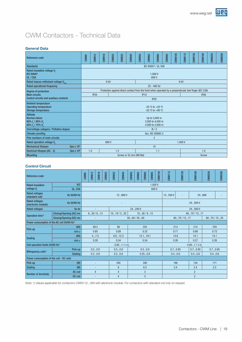
Standards IEC 60947 / UL 508
Rated insulation voltage Ui
IEC 60947 UL / CSA
1,000 V600 V
Rated impuse withstand voltage Uimp 6 kV 8 kV
Rated operational frequency 25 - 400 Hz
Degree of protectionMain circuitsControl circuits and auxiliary contacts
Protection against direct contact from the front when operated by a perpendicular test finger (IEC 536)
IP20 IP10 IP00
IP20
Ambient temperatureOperating temperatureStorage temperature
-25 oC to +55 oC-55 oC to +80 oC
Altitude Normal values 90% Ie / 80% Ue 80% Ie / 75% Ue
Up to 3,000 m 3,000 to 4,000 m 4,000 to 5,000 m
Overvoltage category / Pollution degree III / 3
Climatic proofing Acc. IEC 60680-2
Pole numbers of main circuits 3
Rated operation voltage Ue 690 V 1,000 V
Mechanical lifespan Ops x 106 10
Electrical lifespan (AC - 3) Ops x 106 1.5 1.2 1.1 1.0
Mounting Screw or 35 mm DIN Rail Screw
Control Circuit
General Data
Reference code
CWM
9
CWM
12
CWM
18
CWM
25
CWM
32
CWM
40
CWM
50
CWM
65
CWM
80
CWM
95
CWM
105
CWM
112
CWM
150
CWM
180
CWM
250
CWM
300
Rated insulation voltage Ui
IEC 1,000 V
UL, CSA 600 V
Rated voltages (standard coil)
Us 50/60 Hz 12...660 V 12...550 V - 24...690 -
Rated voltages (electronic module)
Us 50/60 Hz - 24...500 V
Rated voltages Us dc - 24...240 V 24...500 V
Operation time1)Closing/Opening (AC) ms 8...20 / 6...13 10...19 / 5...25 15...30 / 9...15 60...70 / 13...17
Closing/Opening (DC) ms - 50...60 / 55...60 60...70 / 13...17 60...70 / 15...25
Power consumption of the AC coil 50/60 Hz1)
Pick-up (VA) 69.5 98 255 213 214 229
cos ϕ 0.85 0.69 0.32 0.71 0.68 0.73
Sealing(VA) 4...7.2 6.6...12.3 13.1...19.1 14.8 14.1 14.1
cos ϕ 0.28 0.34 0.54 0.26 0.27 0.26
Coil operation limits 50/60 Hz1) 0.85...1.1 x Us 0.65...1.1 x Us
Bifrequency coils1)Pick-up 0.5...0.8 0.5...0.8 0.5...0.8 0.7...0.85 0.7...0.85 0.7...0.85
Sealing 0.2...0.6 0.2...0.6 0.25...0.6 0.4...0.6 0.4...0.6 0.4...0.6
Power consumption of the coil - DC coils
Pick-up (W) - 240 340 166 154 171
Sealing (W) - 6 6.5 2.4 2.4 2.5
Number of terminalsAC coil 4 4 3 2
DC coil - 4 3 2
Note: 1) Values applicable for contactors CWM112...300 with electronic module. For contactors with standard coil only on request.
www.weg.net
19Contactors - CWM Line

Main Contacts
Reference code
CWM
9
CWM
12
CWM
18
CWM
25
CWM
32
CWM
40
CWM
50
CWM
65
CWM
80
CWM
95
CWM
105
CWM
112
CWM
150
CWM
180
CWM
250
CWM
300
Rated operational current Ie
AC-3 (Ue ≤ 440 V) (A) 9 12 18 25 32 40 50 65 80 95 105 112 150 180 250 300
AC-4 (Ue ≤ 440 V) (A) 5 7 8 12 16 18.5 23 30 37 44 50 63 69 73 110 145
AC-1 (θ ≤ 55 °C, Ue ≤ 690 V) (A) 25 25 32 45 60 60 90 110 110 140 140 180 225 225 350 410
Rated operational voltage Ue
IEC/EN 60947-4-1, VDE 0660 (V) 690 1,000
UL, CSA (V) 600
Rated thermal current Ith (θ ≤ 55 °C) (A) 25 25 32 45 60 60 90 110 110 140 140 180 225 225 350 410
Making capacity - IEC/EN 60947 (A) 300 300 300 450 550 550 1,000 1,000 1,000 1,280 1,280 1,430 1,820 2,100 2,600 3,000
Breaking capacity IEC/EN 60947
(Ue≤400 V) (A) 250 250 250 350 450 450 920 920 920 1,050 1,050 1,290 1,350 1,400 2,000 -
(Ue=500 V) (A) 250 250 250 320 450 450 920 920 920 1,050 1,050 1,290 1,350 1,400 2,000 -
(Ue=690 V) (A) 130 130 130 170 205 205 780 780 780 950 950 - - - - -
Short-time currentNo current flowing during recovery time 10 min. and θ ≤ 40 °C)
1 sec (A) 455 455 570 630 1,010 1,265 1,580 2,530 2,530 3,300 3,300 3,165 3,763 4,649 4,427 -
5 sec (A) 205 205 254 280 450 450 710 1,130 1,130 1,485 1,485 1,820 2,164 2,673 2,546 -
10 sec (A) 144 144 180 200 320 400 500 800 800 1,050 1,050 1,430 1,700 2,100 2,000 -
30 sec (A) 85 85 104 115 185 230 290 460 460 600 600 826 980 1,212 1,155
1 min (A) 60 60 74 80 130 165 205 325 325 430 430 584 694 857 816 -
3 min (A) 35 35 46 50 90 100 120 185 185 250 250 337 401 495 471 -
Protection against short-circuits with fuses(gL/gG)
@600 V - UL/CSA (kA) 5 10 18
Coordination type 1 (A) 50 50 63 63 100 125 200 200 200 250 250 - 355 355 500 630
Coordination type 2 (A) 25 35 35 50 63 80 100 125 125 160 200 224 250 250 400 500
Impedance per pole (mΩ) 2.4 2.4 2.4 1.7 1.3 1.0 0.9 0.9 0.9 0.8 0.8 0.5 0.5 0.45 0.3 0.3
Power dissipation per pole
AC-1 (W) 1.5 1.5 2.5 3.3 4.6 3.4 6.7 10.4 10.4 14.9 14.9 16 25 21.6 35 45.7
AC-3 (W) 0.2 0.3 0.8 1.0 1.3 1.5 2.1 3.6 5.5 6.9 8.4 6.2 11.1 13.8 17.9 25.7
Utilization category AC-3
Rated operational current Ie (θ ≤ 55 °C)
Ue ≤ 440 V (A) 9 12 18 25 32 40 50 65 80 95 105 112 150 180 250 300
Ue ≤ 500 V (A) 7.5 10.5 14 19 24 32 38 55 63 79 85 95 130 155 220 265
Ue ≤ 690 V (A) 7 9 13 15 22 25 34 44 48 60 67 82 110 135 185 220
Ue ≤ 1,000 V (A) Not available 19 25 30 37 40 42 48 68 103 126
Rated operational power
220 / 230 V (kW) 2.2 3 4.5 5.5 9.2 11 15 18.5 22 22 30 30 45 55 75 90
(HP) 3 4 6 7.5 12.5 15 20 25 30 30 40 40 60 75 100 125
380 / V (kW) 3.7 5.5 7.5 11 15 18.5 22 30 37 45 55 55 75 90 132 150
(HP) 5 7.5 10 15 20 25 30 40 50 60 75 75 100 125 175 200
400 / 415 V (kW) 3.7 5.5 7.5 11 15 18.5 22 30 37 45 55 55 75 110 132 150
(HP) 5 7.5 10 15 20 25 30 40 50 60 75 75 100 150 175 200
440 V (kW) 4.5 5.5 9.2 11 15 22 30 37 45 55 55 55 90 110 150 185
(HP) 6 7.5 12.5 15 20 30 40 50 60 75 75 75 125 150 200 250
500 V (kW) 4.5 5.5 9.2 11 15 22 30 37 45 55 55 55 90 110 150 185
(HP) 6 7.5 12.5 15 20 30 40 50 60 75 75 75 125 150 200 250
660 / 690 V (kW) 5.5 7.5 11 11 18.5 22 30 37 45 55 55 75 110 110 150 185
(HP) 7.5 10 15 15 25 30 40 50 60 75 75 100 150 150 200 250
Percentage of the maximum operational current at
600 ops./h (%) 100 100 100 100 100 100 100 100 100 100 100 100 100 100 100 100
1,200 ops./h (%) 100 100 100 100 100 100 100 100 100 75 75 75 75 75 75 75
3,000 ops./h (%) 35 35 35 35 35 35 35 35 35 25 25 25 25 25 25 25
Utilization category AC-4
Rated operational current Ie AC-4 (Ue ≤ 690 V) (A) 5 7 8 12 16 18.5 23 30 37 44 50 50 55 58 88 116
Rated operational power
220 / 230 V (kW) 1.1 1.5 1.5 3 3.7 4.5 55 7.5 9.2 11 11 18.5 18.5 22 37 45
(HP) 1.5 2 2 4 5 6 7.5 10 12.5 15 15 25 25 30 50 60
380 / 400 V (kW) 2.2 3 3.7 5.5 7.5 9.2 11 15 18.5 22 22 30 30 37 55 75
(HP) 3 4 5 7.5 10 12.5 15 20 25 30 30 40 40 50 75 100
415 V (kW) 2.2 3.7 4.5 5.5 9.2 11 11 15 22 22 30 37 37 45 55 75
(HP) 3 5 6 7.5 12.5 15 15 20 30 30 40 50 50 60 75 100
440 V (kW) 2.2 3.7 4.5 5.5 9.2 11 11 15 22 22 30 37 37 45 55 75
(HP) 3 5 6 7.5 125 15 15 20 30 30 40 50 50 60 75 100
500 V (kW) 3 3.7 5.5 7.5 9.2 11 15 18.5 22 22 30 37 45 45 75 90
(cv) 4 5 7.5 10 12.5 15 20 25 30 30 40 50 60 60 100 125
660 / 690 V (kW) 3 4.5 5.5 7.5 11 11 15 18.5 22 30 30 45 45 55 90 90
(cv) 4 6 7.5 10 15 15 20 25 30 40 40 60 60 75 125 125
CWM Contactors - Technical Data
www.weg.net
20 Contactors - CWM Line

Main Contacts
UL Power
Reference code
CWM
9
CWM
12
CWM
18
CWM
25
CWM
32
CWM
40
CWM
50
CWM
65
CWM
80
CWM
95
CWM
105
CWM
112
CWM
150
CWM
180
CWM
300
Utilization category AC-1
3P (NO) or 4P (4NO) 3P (NO) 3P (NO)
Rated thermal current Ith (θ ≤ 55 °C) (A) 25 25 32 45 60 60 90 110 110 140 140 180 225 225 410
Max. operational current at ambient temperature of (up to 690 V)
θ ≤ 55 °C (A) 25 25 32 45 60 60 90 110 110 140 140 160 190 200 350
θ ≤ 70 °C (A) 20 20 25 32 48 48 72 88 88 110 110 120 145 145 250
θ ≤ 75 °C (A) 17 17 22 26 42 42 63 77 77 95 95 101 124 120 206
Max. operational powerθ ≤ 55 °C (Three-phase resistors)
220 / 230 V (kW) 9.5 9.5 12 17 22.5 22.5 34 42 42 53 53 68 85 85 156
380 / 400 V (kW) 16.5 16.5 21 29.5 39.5 39.5 59 72.5 72.5 92 92 118 145 145 270
415 / 440 V (kW) 19 19 24 34 45.5 45.5 68.5 84 84 106.5 106.5 130 160 160 295
500 V (kW) 21.5 21.5 27.5 39 52 52 77 95 95 121 121 155 190 190 355
575 / 600 V (kW) 24.1 24.1 30.9 43.4 57.9 57.9 86.8 106.1 106.1 135.1 135.1 180 225 225 400
660 / 690 V (kW) 28.5 28.5 38 51 68.5 68.5 100 125 125 160 160 205 255 255 470
Cable size (mm²) 4 4 6 10 16 16 35 35 35 50 50 120 120 1202 x 150
Current values for connection of
2 poles in parallel Ie x 1.7
3 poles in parallel Ie x 2.4
4 poles in parallel Ie x 3.2
Percentage of the maximum operational current at
600 ops./h (%) 100 100 100 100 100 100 100 100 100 100 100 100 100 100 100
1,200 ops./h (%) 100 100 100 100 100 100 100 100 100 80 80 80 80 80 80
3,000 ops./h (%) 50 50 50 50 50 50 50 50 50 40 40 40 40 40 40
2P (NO/NC) 4P (2NO+2NC)
2P (NO/NC)
Max. operational powerθ ≤ 55 °C (Resistive loads)
220 / 230 V (kW) 5.5 5.5 7.04 9.9 13.2 14.9 22.2 27.5 27.5 34.1 34.1 - - - -
380 / 400 V (kW) 9.5 9.5 12.1 17.1 22.8 25.8 38.6 47.5 47.5 58.9 58.9 - - - -
415 / 440 V (kW) 10.3 10.3 13.2 18.6 24.9 28.2 42.3 51.8 51.8 64.3 64.3 - - - -
500 V (kW) 12.5 12.5 16 22.5 30 34 50.6 62.5 62.5 77.5 77.5 - - - -
660 / 690 V (kW) 16.5 16.5 21.1 29.7 39.6 44.8 66 82.5 82.5 102.3 102.3 - - - -
CWM Contactors - Technical Data
Reference code
CWM
9
CWM
12
CWM
18
CWM
25
CWM
32
CWM
40
CWM
50
CWM
65
CWM
80
CWM
95
CWM
105
CWM
112
CWM
150
CWM
180
CWM
250
CWM
300
General purpose current (600 V) (A) 25 25 32 32 60 60 90 110 110 140 140 170 200 200 300 400
1-phase110 / 120 V (HP) 0.75 0.75 1 2 3 3 5 5 7.5 7.5 10 - - - - -
220 / 240 V (HP) 1.5 2 3 5 5 5 7.5 10 15 15 20 - - - - -
3-phase
200 V (HP) 3 3 5 7.5 10 10 15 20 20 25 30 40 50 60 75 100
220 / 240 V (HP) 3 3 5 7.5 10 15 15 20 25 30 40 50 60 75 100 125
440 / 480 V (HP) 5 7.5 10 15 20 30 40 50 50 60 75 100 125 150 200 250
550 / 600 V (HP) 7.5 10 15 15 25 25 40 50 60 75 75 100 150 200 250 350
www.weg.net
21Contactors - CWM Line
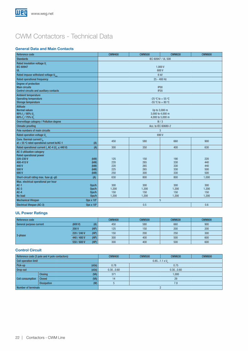
Reference code CWM400 CWM500 CWM630 CWM800
Standards IEC 60947 / UL 508
Rated insulation voltage Ui
IEC 60947 UL
1,000 V600 V
Rated impuse withstand voltage Uimp 6 kV
Rated operational frequency 25 - 400 Hz
Degree of protection Main circuitsControl circuits and auxiliary contacts
IP00IP20
Ambient temperatureOperating temperatureStorage temperature
-25 oC to + 55 oC-55 oC to + 80 oC
AltitudeNormal values 90% Ie / 80% Ue
80% Ie / 75% Ue
Up to 3,000 m 3,000 to 4,000 m 4,000 to 5,000 m
Overvoltage category / Pollution degree III / 3
Climatic proofing Acc. to IEC 60680-2
Pole numbers of main circuits 3
Rated operation voltage Ue 690 V
Conv. thermal current Ith at < 55 oC rated operational current Ie/AC-1 (A)
450 580 660 900
Rated operational current Ie AC-4 (Ue ≤ 440 V) (A) 300 350 400 630
AC-3 utilization categoryRated operational power220-230 V (kW)400-415 V (kW)440 V (kW)500 V (kW)690 V (kW)
125220220225250
150265265265300
190330330330330
220440440500500
Short-circuit rating max. fuse gL-gG (A) 630 800 800 1,000
Max. electrical operational per hourAC-1 Ops/hAC-3 Ops/hAC-4 Ops/hNo load Ops/h
3001,200150
1,200
3001,200150
1,200
3001,200150
1,200
3001,200150
1,200
Mechanical lifespan Ops x 106 5
Electrical lifespan (AC-3) Ops x 106 0.5 0.6
Control Circuit
UL Power Ratings
General Data and Main Contacts
Reference code (3 pole and 4 pole contactors) CWM400 CWM500 CWM630 CWM800
Coil operation limit 0.85...1.1 x Us
Pick-up (xUs) 0.78 0.75
Drop-out (xUs) 0.30...0.60 0.30...0.60
Coil consumption
Closing (VA) 571 1,000
Closed (VA) 14 29
Dissipation (W) 5 7.8
Number of terminals 2
CWM Contactors - Technical Data
Reference code CWM400 CWM500 CWM630 CWM800
General purpose current (600 V) (A) 450 580 660 900
3-phase
200 V (HP) 125 150 200 200
220 / 240 V (HP) 150 200 250 300
440 / 480 V (HP) 300 400 500 600
550 / 600 V (HP) 300 400 500 600
www.weg.net
22 Contactors - CWM Line

CWM Contactors - Technical Data
Terminal Capacity and Tightening Torque - Power TerminalsReference code CWM9 / CWM12 / CWM18 CWM25
Screw typeM3.5x 9
Flat / PhillipsM4x 12
Flat / Phillips
Power terminal capacity1) Finely stranded with end sleeve
Stranded and finely stranded without
end sleeveSolid
Finely stranded with end sleeve
Stranded and finely stranded without
end sleeveSolid
mm²1x 0.5...4
2x 0.5...2.5
1x 1...6 2x 1...2.5 2x 2.5...6
1x 0.5...6 2x 0.5...2.5 2x 2.5...6
1x 1...10 2x 1...2.5 2x 2.5...6
1x 2.5...10 2x 2.5...10
1x 1...10 2x 1...2.5 2x 2.5...10
AWG (UL)
14...10 14...8
Tightening torque (N.m) 1...1.5 1.6...2.5
Tightening torque (lb.in) (UL)
15 16
Reference code CWM32 / CWM40 CWM50 / CWM65 / CWM80 CWM95 / CWM105
Screw typeM4x 16.5
Flat / PhillipsM8
Allen 4mmM10
Allen 4mm
Power terminal capacity
Finely stranded with end sleeve
Stranded and finely stranded
without end sleeve
Solid
Finely stranded with end sleeve
Stranded and finely stranded
without end sleeve
Solid
Finely stranded with end sleeve
Stranded and finely stranded
without end sleeve
Solid
One conductor on bottom
mm² 1...16 1.5...16 1...16 2.5...35 6...35 2.5...35 4...35 6...35 4...35
AWG (UL)
14...8 14...1/0 10...1/0
One conductor on top
mm² 0.75...16 1...16 0.75...16 1...35 1.5...35 1...35 1.5...50 2.5...50 1.5...50
AWG (UL)
14...8 14...1/0 10...1/0
Two conductors at the same time - bottom conductor
mm² 1...16 1.5...16 1...16 2.5...25 6...35 2.5...35 4...35 6...35 4...35
AWG (UL)
14...8 14...1/0 10...1/0
Two conductors at the same time - top conductor
mm² 0.75...16 1...16 0.75...16 1...25 1.5...35 1...35 1.5...50 2.5...50 1.5...50
AWG (UL)
14...8 14...1/0 10...1/0
Tightening torque (N.m) 2...2.5 4...6 5...6.5
Tightening torque (lb.in) (UL)
22 40 60
Note: this information is also valid for built-in auxiliary terminals for CWM9 to CWM18.
Reference codeCWM112 / CWM150
CWM180CWM250 / CWM300
CWM400CWM500 / CWM630
CWM800
Screw typeM6
Hexagon headM8
Hexagon headM10
Hexagon headM12
Hexagon headM16
Hexagon headM16
Hexagon head
Main terminal capacity
Solid and
stranded with end sleeve
Busbars
Solid and
stranded with end sleeve
Busbars
Solid and
stranded with end sleeve
Busbars
Solid and
stranded with end sleeve
Busbars
Solid and
stranded with end sleeve
Busbars
Solid and
stranded with end sleeve
Busbars
mm²2x
25...702 x
(15 x 3)2x
50...1202 x
(20 x 3)2x
50...1502 x
(30 x 5)2x
120...1852x
(30x5)2x
185...3002x
(50x5)2x
185...3002x
(60x5)
AWG (UL)
2x 2...3/0
-2x
1/0...250-
2x 1/0...300
-2x
250...400-
2x 400...600
-2x
400...600-
Tightening torque (N.m) 5.4...6 14...16 23...26 23...26 54...60
www.weg.net
23Contactors - CWM Line

CWM Contactors - Technical Data
Reference code CWM9...105 CWM112...300
Screw typeM3.5x 10
Flat / PhillipsM3.5x 10
Flat / Phillips
Coil terminalFinely stranded with
end sleeveStranded and finely stranded
without end sleeveSolid
Finely stranded with end sleeve
Stranded and finely stranded without end sleeve
Solid
mm²1x 0.5...4
2x 0.5...1.5 2x 1...2.5
1x 1...4 2x 1...2.5
1x 0.5...4 2x 0.5...1.5 2x 1...2.5
1x 0.5...4 2x 0.5...1.5 2x 1...2.5
1x 1...4 2x 1...2.5
1x 0.5...4 2x 0.5...1.5 2x 1...2.5
AWG (UL)
1x 20...10 2x 20...14 2x 16...12
1x 16...10 2x 16...12
1x 20...10 2x 20...14 2x 16...12
1x 20...10 2x 20...14 2x 16...12
1x 16...10 2x 16...12
1x 20...10 2x 20...14 2x 16...12
Tightening torque (N.m) 0.8...1.1 0.8...1.1
Tightening torque (lb.in) (UL)
10 10
Reference code CWM400...CWM800
Screw typeM4
Flat / Phillips
Coil terminal Finely stranded with end sleeve Stranded and finely stranded without end sleeve Solid
mm²1x 1.25...5.5 or
2x 1.25...5.5
AWG (UL)
16...10
Tightening torque (N.m) 2...2.3
Tightening torque (lb.in) (UL)
17.7...20.3
Reference codeBCXMF BCXML
Screw typeM3.5x9
Fenda / Philips
Auxiliary contact block Finely stranded with end sleeve Stranded and finely stranded without end sleeve Solid
mm²1x 0.5...4
2x 0.5...2.51x 0.75...2.5 2x 0.75...2.5
1x 0.5...4 2x 0.5...2.5
AWG (UL)
22...12
Tightening torque (N.m) 0.8...1.1
Tightening torque (lb.in) (UL)
10
Terminal Capacity and Tightening Torque - Coil Terminals
Terminal Capacity and Tightening Torque - Auxiliary Contact Blocks
www.weg.net
24 Contactors - CWM Line
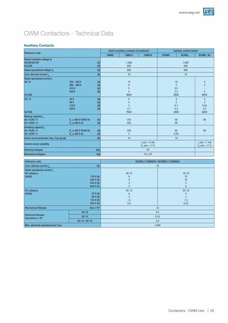
Reference code BCXML11 CWM800 / BCXMRL11 CWM800
Conv. thermal current Ith (A) 16
Rated operational current Ie AC category (A600) 110 V (A)
220 V (A)440 V (A)600 V (A)
AC-15
6533
AC-12
101055
DC category (P600)
24 V (A)48 V (A)
110 V (A)220 V (A)
DC-1363
1.20.2
DC-12 53
1.30.25
Mechanical lifespan Ops x 106 10
Electrical lifespan Operations x 106
AC-15 0.5
AC-12 0.25
DC-13 / DC-12 0.5
Max. electrical operational per hour 1,800
CWM Contactors - Technical Data
Reference code Built-in auxiliary contacts of contactors Auxiliary contact blocks
CWM9 CWM12 CWM18 BCXMF... BCXML... BCXMF_AU
Rated insulation voltage Ui
IEC/EN 60 947UL/CSA
(V)(V)
1,000600
1,000 600
Rated operational voltage Ue (V) 690 690
Conv. thermal current Ith (A) 16 10
Rated operational current IeAC-15
UL/CSA
220 - 240 V 380 - 400 V 415 V 500 V
(A)(A)(A)(A)
106 54
A600
10 4
3.5 2.5
A600
4 3- 2
A600
DC-13
UL/CSA
24 V 48 V110 V 220 V
(A)(A)(A)(A)
6 4 2
0.7P600
42
0.70.3
Q600
42
0.550.3
Q600
Making capacity ImAC-15/AC-11 AC-13/DC-11
Ue ≤ 400 V 50/60 HzUe ≤ 220 V dc
(A)(A)
250250
90 90
90 -
Breaking capacity Ic AC-15/AC-11 AC-13/DC-11
Ue ≤ 400 V 50/60 HzUe ≤ 220 V dc
(A)(A)
2502
60 0.95
60 -
Short-circuit protection max. fuse gL/gG (A) 10 10
Control circuit reliability le
min = 5 mA Ue min = 17 V
le min = 1 mA
Ue min = 17 V
Electrical lifespan Ops 106
Mechanical lifespan Ops 10 x 106
Auxiliary Contacts
www.weg.net
25Contactors - CWM Line

CWM Contactors - Technical Data
Contactors for Lighting CircuitsMaximum number of lamps per phase at 220 V
Lamp type W A µF CWM9 CWM12 CWM18 CWM25 CWM32 CWM40 CWM50 CWM65 CWM80 CWM95 CWM105
Incandescent
60 0.27 - 62 62 70 77 85 122 156 191 222 264 284
100 0.45 - 40 40 50 60 66 73 95 116 133 160 170
200 0.91 - 20 20 25 30 33 36 47 58 66 79 84
300 1.36 - 13 13 17 20 22 24 31 38 44 53 56
500 2.27 - 8 8 10 12 12 14 19 23 26 31 33
1,000 4.50 - 4 4 5 6 6 7 9 11 13 16 16
2,000 9.1 - 1 1 2 3 3 3 4 5 6 8 8
AC-5b¹) (A) 18 18 23 27 30 33 43 52 60 73 77
FluorescentSingle arrangementWithout compensation
15 0.23 - 88 98 126 155 224 237 355 390 434 496 553
20 0.37 - 57 61 78 110 139 147 221 243 270 309 344
40 0.44 - 48 51 66 93 118 124 186 204 227 260 289
65 0.7 - 30 32 41 58 74 78 116 127 142 163 181
100 1.5 - 14 16 19 27 34 36 54 59 66 76 85
FluorescentSingle arrangementWith compensation
15 0.23 3.5 61 77 94 111 134 149 191 232 273 312 347
20 0.25 4.5 48 61 74 87 103 115 148 180 212 243 270
40 0.3 4.5 48 61 74 87 103 115 148 180 212 243 270
65 0.45 7 31 39 47 56 66 74 95 115 136 155 173
100 0.7 18 11 14 17 21 23 29 37 45 53 60 67
High pressureMercury vapourWithout compensation
250 2.13 - 6 8 10 12 15 18 27 30 33 36 42
400 3.25 - 4 5 6 8 10 12 18 20 22 24 28
700 5.4 - 2 3 4 5 6 7 11 12 13 14 17
1,000 7.5 - 2 2 3 3 4 5 8 9 9 10 12
High pressureMercury vapourWith compensation
250 1.3 20 11 14 18 22 27 33 49 55 60 66 77
400 2.1 25 7 9 11 14 17 20 31 34 37 41 48
700 3.6 40 4 5 6 8 10 12 18 20 22 24 28
1,000 5.3 60 3 3 4 5 7 8 12 13 15 16 19
High pressureSodium vapourWithout compensation
250 3 - 4 5 7 9 11 13 19 21 24 26 30
400 4.4 - 3 4 5 6 7 9 13 15 16 18 20
1,000 10.3 - 1 2 2 2 3 4 6 6 7 7 9
High pressureSodium vapourWith compensation
250 1.45 40 10 12 16 20 25 30 44 49 54 59 69
400 2.5 45 6 7 9 11 14 17 26 29 31 34 40
1,000 5.5 100 3 3 4 5 6 8 12 13 14 16 18
Metal iodide Without compensation
250 2.17 - 4 5 7 9 12 12 19 21 23 25 29
400 3.48 - 3 3 4 6 8 8 12 13 14 16 18
700 6.09 - 1 2 2 3 4 4 7 7 8 9 10
1,000 8.7 - 1 1 2 2 3 3 5 5 6 6 7
2,000 17.39 - 1 1 1 1 2 2 2 3 3 3 4
Metal iodideWith compensation
250 1.4 32 7 9 11 16 21 21 32 36 39 43 50
400 2 45 5 6 8 11 15 15 23 25 28 30 35
700 3.6 65 3 3 4 6 8 8 13 14 15 17 19
1,000 5.3 85 2 2 3 4 6 6 8 9 10 11 13
2,000 10.6 100 1 1 2 2 3 3 4 5 5 6 7
Note: indicative values - It’s highly recommended to take into consideration the values of making capacity and rated AC-1 current when dimensioning the contactor for AC-5b utilization category (AC-5b - Switching of incandescent lamps).
www.weg.net
26 Contactors - CWM Line

Contactors for Lighting CircuitsMaximum number of lamps per phase at 220 V
Lamp type W A µF CWM112 CWM150 CWM180 CWM250 CWM300
Incandescent
60 0.27 - 318 404 467 578 667
100 0.45 - 193 245 283 350 404
200 0.91 - 95 121 140 173 200
300 1.36 - 64 81 93 116 133
500 2.27 - 38 49 56 69 80
1,000 4.50 - 19 24 28 35 40
2,000 9.1 - 10 12 14 17 20
AC-5b¹) (A) 87 110 127 158 182
FluorescentSingle arrangementWithout compensation
15 0.23 - 652 815 978 1,522 1,783
20 0.37 - 405 507 608 946 1,108
40 0.44 - 341 426 511 795 932
65 0.7 - 214 268 321 500 586
100 1.5 - 100 125 150 233 273
FluorescentSingle arrangementWith compensation
15 0.23 3.5 409 520 600 743 857
20 0.25 4.5 318 404 467 578 667
40 0.3 4.5 318 404 467 578 667
65 0.45 7 204 260 300 371 429
100 0.7 18 79 101 117 144 167
High pressureMercury vapourWithout compensation
250 2.13 - 54 62 68 106 124
400 3.25 - 36 40 45 69 81
700 5.4 - 21 24 27 42 49
1,000 7.5 - 15 18 19 30 35
High pressureMercury vapourWith compensation
250 1.3 20 79 100 116 143 165
400 2.1 25 63 80 92 114 132
700 3.6 40 39 50 58 72 83
1,000 5.30 60 26 33 39 48 55
High pressureSodium vapourWithout compensation
250 3.0 - 39 44 48 75 88
400 4.4 - 26 30 33 51 60
1,000 10.3 - 11 13 14 22 26
High pressureSodium vapourWith compensation
250 1.45 40 45 57 66 81 94
400 2.5 45 40 51 58 72 83
1,000 5.5 100 18 23 26 33 38
Metal iodide Without compensation
250 2.17 - 37 42 47 73 85
400 3.48 - 23 26 29 45 53
700 6.09 - 13 15 17 26 30
1,000 8.7 - 9 11 12 18 21
2,000 17.39 - 5 5 6 9 11
Metal iodideWith compensation
250 1.4 32 56 71 82 102 117
400 2 45 40 51 58 72 83
700 3.6 65 28 35 40 50 58
1,000 5.3 85 21 27 31 38 44
2,000 10.6 100 18 23 26 33 38
Note: indicative values - It’s highly recommended to take into consideration the values of making capacity and rated AC-1 current when dimensioning the contactor for AC-5b utilization category (AC-5b - Switching of incandescent lamps).
CWM Contactors - Technical Data
www.weg.net
27Contactors - CWM Line
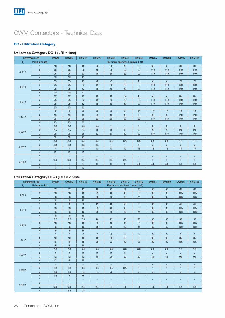
DC - Utilization Category
Utilization Category DC-1 (L/R ≤ 1ms)Reference code CWM9 CWM12 CWM18 CWM25 CWM32 CWM40 CWM50 CWM65 CWM80 CWM95 CWM105
Ue Poles in series Maximum operational current Ie (A)
≤ 24 V
1 18 18 18 25 32 40 50 65 65 80 80
2 25 25 32 45 60 60 90 110 110 140 1403 25 25 32 45 60 60 90 110 110 140 1404 25 25 32 -
≤ 48 V
1 15 15 15 20 25 35 45 55 55 70 702 25 25 32 45 60 60 90 110 110 140 1403 25 25 32 45 60 60 90 110 110 140 1404 25 25 32 -
≤ 60 V
1 12 12 12 18 18 32 40 50 50 65 652 25 25 32 45 60 60 90 110 110 140 1403 25 25 32 45 60 60 90 110 110 140 1404 25 25 32 -
≤ 125 V
1 6 6 6 8 8 8 16 16 16 16 162 18 18 18 25 45 45 80 90 90 110 1103 25 25 25 32 60 60 90 110 110 140 1404 25 25 32 -
≤ 220 V
1 0.8 0.8 0.8 0.8 1 1 2 2 2 2 22 7.5 7.5 7.5 8 8 8 20 20 20 20 203 25 25 25 32 50 50 90 110 110 140 1404 25 25 32 -
≤ 440 V
1 0.4 0.4 0.4 0.4 0.5 0.5 0.8 0.8 0.8 0.8 0.82 0.8 0.8 0.8 0.8 1 1 2 2 2 2 23 8 8 8 10 10 10 15 15 15 15 154 15 15 15 -
≤ 600 V
1 - - - - - - - - - - -2 0.4 0.4 0.4 0.4 0.5 0.5 1 1 1 1 13 4 4 4 5 5 5 7.5 7.5 7.5 7.5 7.5
4 8 8 10 -
Utilization Category DC-3 (L/R ≤ 2.5ms)Reference code CWM9 CWM12 CWM18 CWM25 CWM32 CWM40 CWM50 CWM65 CWM80 CWM95 CWM105
Ue Poles in series Maximum operational current Ie (A)
≤ 24 V
1 12 12 12 18 25 32 40 50 50 65 652 18 18 18 25 40 40 65 80 80 105 1053 18 18 18 25 40 40 65 80 80 105 1054 18 18 18 -
≤ 48 V
1 9 9 9 12 18 20 30 35 35 45 452 18 18 18 25 40 40 65 80 80 105 1053 18 18 18 25 40 40 65 80 80 105 1054 18 18 18 -
≤ 60 V
1 7.5 7.5 7.5 10 15 15 25 30 30 35 352 18 18 18 25 40 40 65 80 80 105 1053 18 18 18 25 40 40 65 80 80 105 1054 18 18 18 -
≤ 125 V
1 2 2 2 2 3 3 3 3 3 3 32 10 10 12 18 25 32 50 60 60 85 853 15 15 18 25 32 40 65 80 80 105 1054 15 15 18 -
≤ 220 V
1 0.6 0.6 0.6 0.6 0.6 0.6 0.8 0.8 0.8 0.8 0.82 2 2 2 2 2 2 7 7 7 7 73 12 12 12 18 25 32 50 65 65 95 954 12 15 18 -
≤ 440 V
1 - - - - - - - - - - -2 0.3 0.3 0.3 0.3 0.5 0.5 1 1 1 1 13 1.5 1.5 1.5 1.5 3 3 3 3 3 3 34 1.5 6 6 -
≤ 600 V
1 - - - - - - - - - - -2 - - - - - - - - - - -3 0.8 0.8 0.8 0.8 1.5 1.5 1.5 1.5 1.5 1.5 1.54 1 2.5 2.5 -
CWM Contactors - Technical Data
www.weg.net
28 Contactors - CWM Line
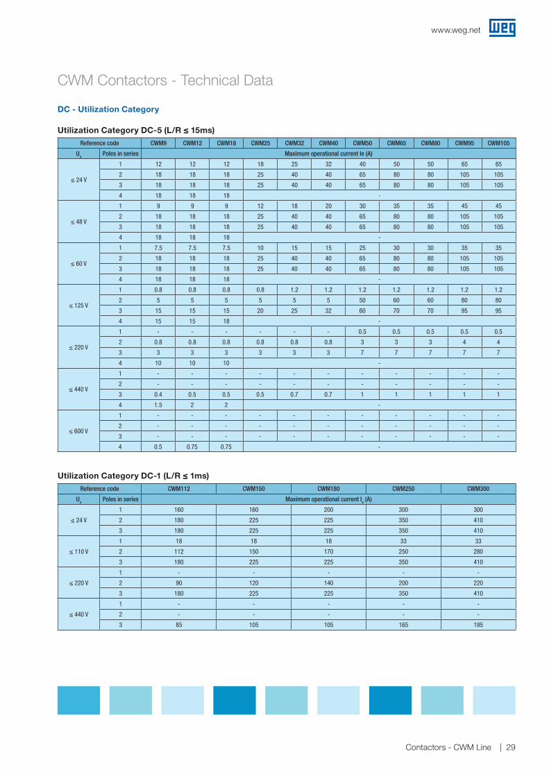
DC - Utilization Category
Utilization Category DC-1 (L/R ≤ 1ms)
Reference code CWM9 CWM12 CWM18 CWM25 CWM32 CWM40 CWM50 CWM65 CWM80 CWM95 CWM105
Ue Poles in series Maximum operational current Ie (A)
≤ 24 V
1 12 12 12 18 25 32 40 50 50 65 65
2 18 18 18 25 40 40 65 80 80 105 105
3 18 18 18 25 40 40 65 80 80 105 105
4 18 18 18 -
≤ 48 V
1 9 9 9 12 18 20 30 35 35 45 45
2 18 18 18 25 40 40 65 80 80 105 105
3 18 18 18 25 40 40 65 80 80 105 105
4 18 18 18 -
≤ 60 V
1 7.5 7.5 7.5 10 15 15 25 30 30 35 35
2 18 18 18 25 40 40 65 80 80 105 105
3 18 18 18 25 40 40 65 80 80 105 105
4 18 18 18 -
≤ 125 V
1 0.8 0.8 0.8 0.8 1.2 1.2 1.2 1.2 1.2 1.2 1.2
2 5 5 5 5 5 5 50 60 60 80 80
3 15 15 15 20 25 32 60 70 70 95 95
4 15 15 18 -
≤ 220 V
1 - - - - - - 0.5 0.5 0.5 0.5 0.5
2 0.8 0.8 0.8 0.8 0.8 0.8 3 3 3 4 4
3 3 3 3 3 3 3 7 7 7 7 7
4 10 10 10 -
≤ 440 V
1 - - - - - - - - - - -
2 - - - - - - - - - - -
3 0.4 0.5 0.5 0.5 0.7 0.7 1 1 1 1 1
4 1.5 2 2 -
≤ 600 V
1 - - - - - - - - - - -
2 - - - - - - - - - - -
3 - - - - - - - - - - -
4 0.5 0.75 0.75 -
Reference code CWM112 CWM150 CWM180 CWM250 CWM300
Ue Poles in series Maximum operational current Ie (A)
≤ 24 V
1 160 160 200 300 300
2 180 225 225 350 410
3 180 225 225 350 410
≤ 110 V
1 18 18 18 33 33
2 112 150 170 250 280
3 180 225 225 350 410
≤ 220 V
1 - - - - -
2 90 120 140 200 220
3 180 225 225 350 410
≤ 440 V
1 - - - - -
2 - - - - -
3 85 105 105 165 195
Utilization Category DC-5 (L/R ≤ 15ms)
CWM Contactors - Technical Data
www.weg.net
29Contactors - CWM Line
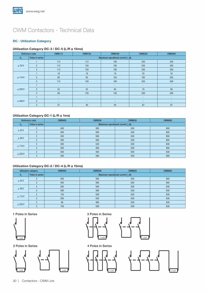
Utilization Category DC-3 / DC-5 (L/R ≤ 15ms)
Utilization Category DC-1 (L/R ≤ 1ms)
Utilization Category DC-2 / DC-4 (L/R ≤ 15ms)
Reference code CWM112 CWM150 CWM180 CWM250 CWM300
Ue Poles in series Maximum operational current Ie (A)
≤ 24 V
1 112 112 180 250 250
2 112 150 180 250 300
3 112 150 180 250 300
≤ 110 V
1 18 18 18 33 33
2 80 95 105 185 205
3 112 150 180 250 300
≤ 220 V
1 - - - - -
2 55 55 65 70 80
3 80 120 150 200 200
≤ 440 V
1 - - - - -
2 - - - - -
3 27 40 50 67 67
Reference code CWM400 CWM500 CWM630 CWM800
Ue Poles in series Maximum operational current Ie (A)
≤ 24 V2 400 580 630 800
3 400 580 630 800
≤ 48 V2 240 580 630 800
3 400 580 630 800
≤ 110 V2 200 520 630 630
3 400 580 630 800
≤ 220 V2 200 450 630 630
3 300 580 630 800
Utilisation category CWM400 CWM500 CWM630 CWM800
Ue Poles in series Maximum operational current Ie (A)
≤ 24 V2 400 580 630 800
3 400 580 630 800
≤ 48 V2 200 580 630 630
3 280 580 630 630
≤ 110 V2 150 500 630 630
3 200 550 630 630
≤ 220 V2 90 480 630 630
3 150 500 630 630
1 Poles in Series
2 Poles in Series
3 Poles in Series
4 Poles in Series
LoadLoadLoadLoad
Load Load Load
CWM Contactors - Technical Data
DC - Utilization Category
www.weg.net
30 Contactors - CWM Line

DiagramDistinctive number
and version ofcombination
NO NC Reference code Additional
auxiliary contactblocks
Without auxiliary contact blocks
10E 1 0CWM9-10CWM12-10CWM18-10
-
01E 0 1
CWM9-01CWM12-01CWM18-01
-
Front mounting auxiliary contact blocks BCXMF10 or BCXMF01
11E 1 1
CWM9-10
CWM12-10
CWM18-10
+ BCXMF01
21E 2 1CWM9-10CWM12-10CWM18-10
+ BXCMF10
+ BCXMF01
12E 1 2
CWM9-10
CWM12-10
CWM18-10
+ 2 BXCMF01
31E 3 1
CWM9-10
CWM12-10
CWM18-10
+ 2 BXCMF10
+ BCXMF01
41E 4 1
CWM9-10
CWM12-10
CWM18-10
+ 3 BXCMF10
+ BCXMF01
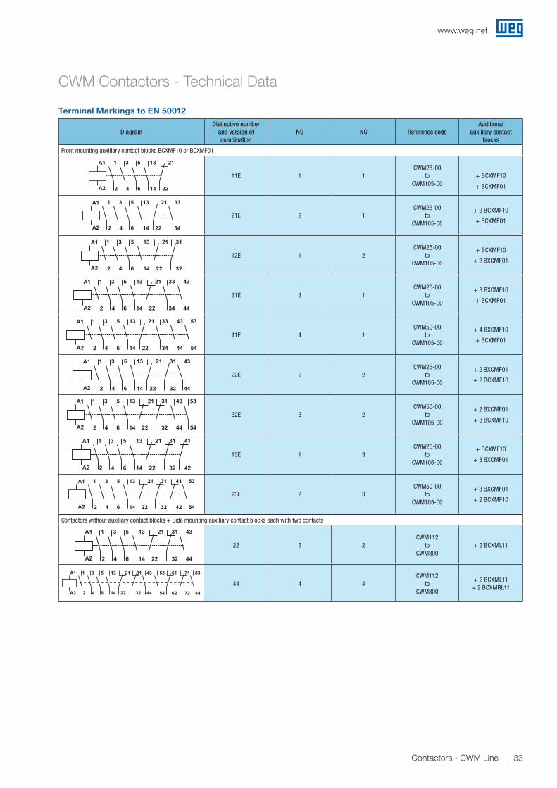
Terminal Markings to EN 50012
CWM Contactors - Technical Data
www.weg.net
31Contactors - CWM Line

DiagramDistinctive number
and version ofcombination
NO NC Reference code Additional
auxiliary contactblocks
Front mounting auxiliary contact blocks BCXMF10 or BCXMF01
22E 2 2
CWM9-10
CWM12-10
CWM18-10
+ 2 BXCMF01
+ BCXMF10
32E 3 2
CWM9-10
CWM12-10
CWM18-10
+ 2 BXCMF01
+ 2 BCXMF10
13E 1 3
CWM9-10
CWM12-10
CWM18-10
+ 3 BXCMF01
23E 2 3
CWM9-10
CWM12-10
CWM18-10
+ 3 BXCMF01
+ BCXMF10
Side mounting auxiliary contact blocks each with two contacts
11E 1 1CWM25-00
toCWM105-00
+ BCXML11
31E 3 1CWM25-00
toCWM105-00
+ BCXML11+ BCXML20
22E 2 2CWM25-00
toCWM105-00
+ 1 BCXML11+ 1 BCXMRL11
Without auxiliary contact blocks
- 0 0CWM25-00
toCWM105-00
-
Front mounting auxiliary contact blocks BCXMF10 or BCXMF01
10E 1 0CWM25-00
toCWM105-00
+ BCXMF10
01E 0 1CWM25-00
toCWM105-00
+ BCXMF01
Terminal Markings to EN 50012
CWM Contactors - Technical Data
www.weg.net
32 Contactors - CWM Line
DiagramDistinctive number
and version ofcombination
NO NC Reference code Additional
auxiliary contactblocks
Front mounting auxiliary contact blocks BCXMF10 or BCXMF01
11E 1 1CWM25-00
toCWM105-00
+ BCXMF10
+ BCXMF01
21E 2 1CWM25-00
toCWM105-00
+ 2 BCXMF10
+ BCXMF01
12E 1 2CWM25-00
toCWM105-00
+ BCXMF10
+ 2 BXCMF01
31E 3 1CWM25-00
toCWM105-00
+ 3 BXCMF10
+ BCXMF01
41E 4 1CWM50-00
toCWM105-00
+ 4 BXCMF10
+ BCXMF01
22E 2 2CWM25-00
toCWM105-00
+ 2 BXCMF01
+ 2 BCXMF10
32E 3 2CWM50-00
toCWM105-00
+ 2 BXCMF01
+ 3 BCXMF10
13E 1 3CWM25-00
toCWM105-00
+ BCXMF10
+ 3 BXCMF01
23E 2 3CWM50-00
toCWM105-00
+ 3 BXCMF01
+ 2 BCXMF10
Terminal Markings to EN 50012
CWM Contactors - Technical Data
Contactors without auxiliary contact blocks + Side mounting auxiliary contact blocks each with two contacts
22 2 2CWM112
toCWM800
+ 2 BCXML11
44 4 4CWM112
toCWM800
+ 2 BCXML11+ 2 BCXMRL11
5343312113531A1
A2 2 4 6 14 22 32 44 54
61
62
71
72
83
84
www.weg.net
33Contactors - CWM Line
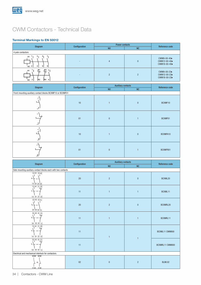
Terminal Markings to EN 50012
Diagram ConfigurationPower contacts
Reference codeNO NC
4 pole contactors
- 4 0CWM9-00-40♦CWM12-00-40♦CWM18-00-40♦
- 2 2CWM9-00-22♦CWM12-00-22♦CWM18-00-22♦
Diagram ConfigurationAuxiliary contacts
Reference codeNO NC
Front mounting auxiliary contact blocks BCXMF10 or BCXMF01
10 1 0 BCXMF10
01 0 1 BCXMF01
10 1 0 BCXMFA10
01 0 1 BCXMFR01
1
2
3
4
5
6
7
8
1
2
R1
R2
R3
R4
3
4
Diagram ConfigurationAuxiliary contacts
Reference codeNO NC
Side mounting auxiliary contact blocks each with two contacts
20 2 0 BCXML20
11 1 1 BCXML11
20 2 0 BCXMRL20
11 1 1 BCXMRL11
11
11
BCXML11 CWM800
11 BCXMRL11 CWM800
Electrical and mechanical interlock for contactors
02 0 2 BLIM.02
CWM Contactors - Technical Data
A1
A1
A2
A2
www.weg.net
34 Contactors - CWM Line

Electrical Lifespan
AC-3 (Ue ≤ 440 V ac)
Num
ber o
f ope
ratio
ns (1
06 )
CWM Contactors - Technical Data
CWM
400
CWM
630
CWM
800
CWM
500
CWM
9
CWM
12
CWM
18
CWM
32
CWM
40
CWM
50
CWM
65CW
M80
CWM
95CW
M10
5CW
M11
2
CWM
150
CWM
180
CWM
250
CWM
300
CWM
25
1 10 18 32 65 100 150 300 1,000
0.1
1
10
Num
ber o
f ope
ratio
ns (1
06 )
Rated operational current Ie (A)
Rated operational current Ie (A)1,000
0.1
www.weg.net
35Contactors - CWM Line

Breaking current Ic (A)
Num
ber o
f ope
ratio
ns (1
06 )
AC-4 (Ue ≤ 440 V ac)
CWM
9
CWM
12
CWM
18
CWM
32
CWM
40
CWM
50
CWM
65CW
M80
CWM
95CW
M10
5
CWM
25
CWM
112
CWM
150
CWM
180
CWM
250
CWM
300
Breaking current Ic (A)
Num
ber o
f ope
ratio
ns (1
06 )
Electrical Lifespan
CWM Contactors - Technical Data
1,000
0.01
0.1
10,000
0.01
0.1
www.weg.net
36 Contactors - CWM Line

Electrical Lifespan
AC-4 (Ue ≤ 440 V ac)
Breaking current Ic (A) - AC-4
Num
ber o
f ope
ratio
ns (1
05 )
Breaking current Ic (A) - AC-4
AC-1 (Ue ≤ 690 V ac)
Num
ber o
f ope
ratio
ns (1
05 )CWM Contactors - Technical Data
,
,
,
CWM
400
CWM
630
CWM
800
CWM
500
1 322510 6045 90 110 140 1.000
CWM
9
CWM
12
CWM
18
CWM
25
CWM
32CW
M40
CWM
50
CWM
65
CWM
80
CWM
95CW
M10
5
0,1
1
10
1,000
1.0
0.1
0.01
0.11,000
www.weg.net
37Contactors - CWM Line
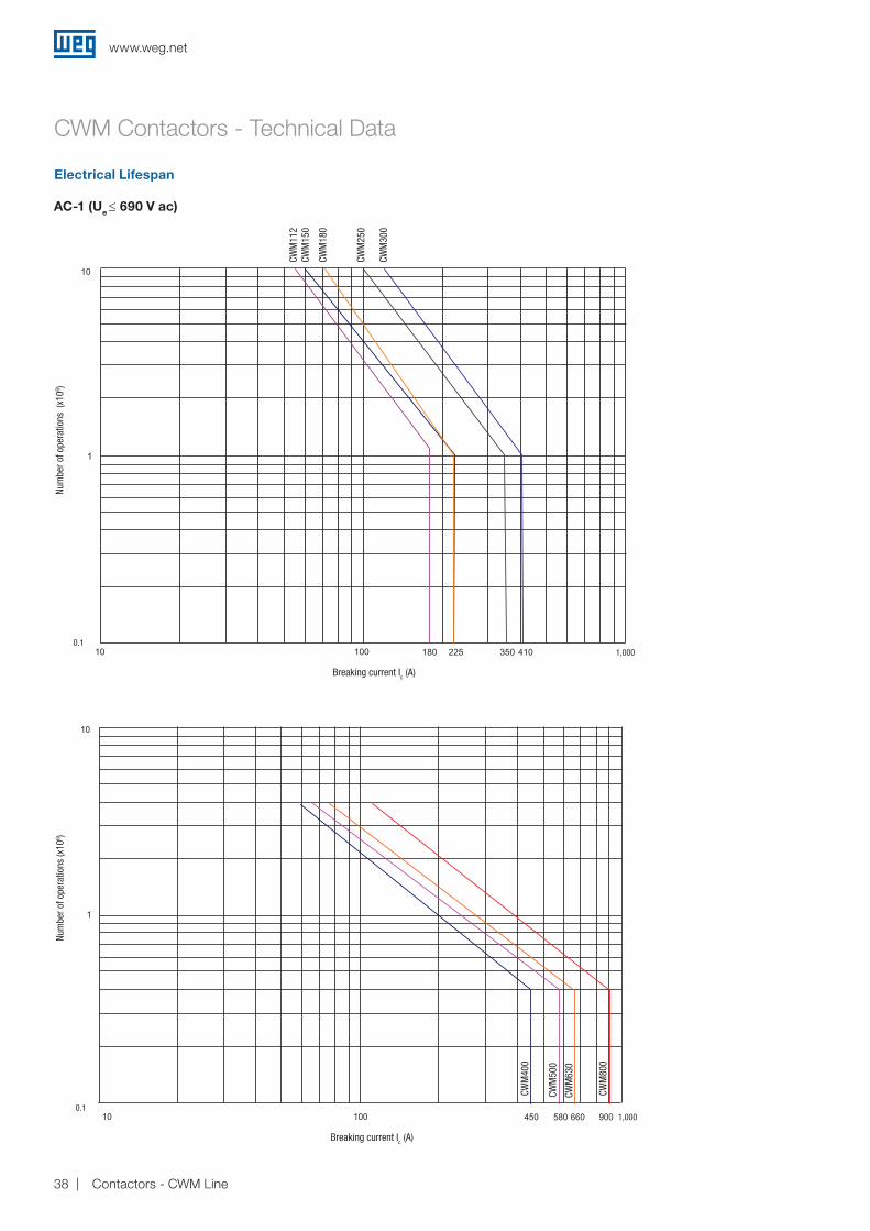
AC-1 (Ue ≤ 690 V ac)
Electrical Lifespan
CWM Contactors - Technical Data
Num
ber o
f ope
ratio
ns (
x106 )
CWM
112
CWM
150
CWM
180
CWM
250
CWM
300
Breaking current Ic (A)
Breaking current Ic (A)
CWM
400
CWM
500
CWM
630
CWM
800
Num
ber o
f ope
ratio
ns (x
106 )
1,0000.1
1,0000.1
www.weg.net
38 Contactors - CWM Line

CWM25
CWM32 and CWM40
CWM Contactors - Dimensions (mm)
CWM50, CWM65 and CWM80
CWM9, CWM12 and CWM18
CoilAC DC
A = 98 A = 118
CoilAC DC
A = 116 A = 116
35
BCXML
BCXML BCXML
BCXML
68
11.5 45 11.5
BCXMF
BCXMF
DIN RAIL35 mm
DIN RAIL35 mm
DIN RAIL35 mm
DIN RAIL35 mm
A 29
BCXMF
77.5 81
4.8
4.8
72,5
4.5
35
44.98
78
11.5 11.555
16.5
16.5
12.5
4.5
70
90
60
56
7.5
5.5 4.5
6
112
BCXML BCXML
77.7
116.
5
100
A 29
BCXMF
11.5 11.5
89
66
BCXML
77.7 89 87
BCXML
79
68
11.5 11.545
77.7 81
A 29
BCXMF
10
4.5
72.5
10
87
87
www.weg.net
39Contactors - CWM Line
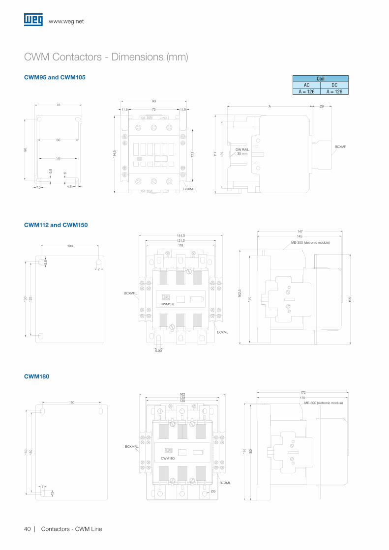
CWM Contactors - Dimensions (mm)
CWM95 and CWM105
CWM180
CoilAC DC
A = 126 A = 126
CWM112 and CWM150
DIN RAIL35 mm
90
70
100
110
BCXMRL
CWM180
162 172
170139135
BCXML
183
180
Ø9
160
150
7
12
144.5147
145
ME-300 (eletronic module)
ME-300 (eletronic module)
CWM150
BCXML
162,
5
150
155
121.5118
BCXMRL
7
9.5
130
125
60
56 114.
511.5 11.575
98
A 29
BCXMF
77.7
117
100
5.5
6
7.5 4.5BCXML
5.90
www.weg.net
40 Contactors - CWM Line

CWM250 and CWM300
B
Models A B C D
CWM9...25 35 72.5 22 102
CWM32...40 45 79 22 122
CWM50...80 57 90 21 144
CWM95...105 57 90 29.8 153
A C A
11.5 84.5
BLIM112-300
Models A B C D
CWM112...150 100 130 51 272.5
CWM180 110 160 58.5 303.5
CWM250...300 120 180 57 325.4
A AC
B 51
64.5
D
CWM Contactors - Dimensions (mm)
ME-300 (electronic module)
120
180
BCXMRL
BCXML
Ø11
171.4
148.4
144
175
10.5
13
200
181
205
BLIM9-105 and BLIM.02
www.weg.net
41Contactors - CWM Line
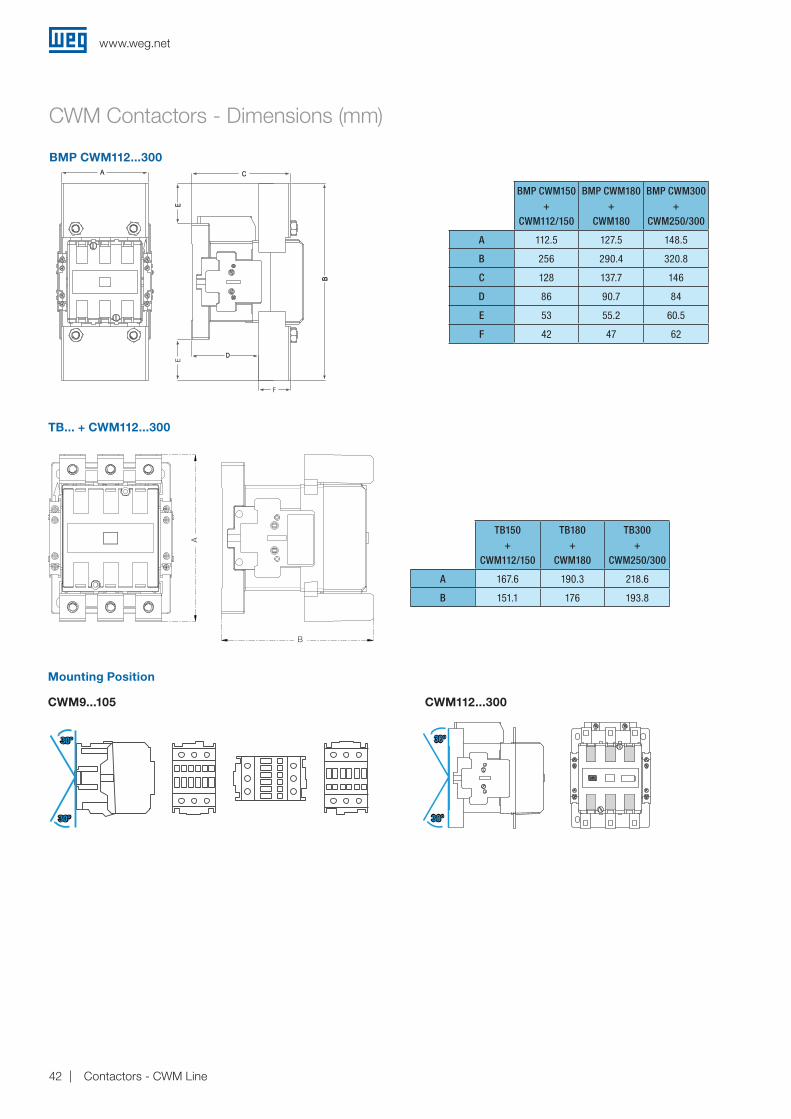
BMP CWM112...300
Mounting Position
CWM9...105 CWM112...300
30°30°
30°30°
30°30°
30°30°
CWM Contactors - Dimensions (mm)
BMP CWM150+
CWM112/150
BMP CWM180+
CWM180
BMP CWM300+
CWM250/300
A 112.5 127.5 148.5
B 256 290.4 320.8
C 128 137.7 146
D 86 90.7 84
E 53 55.2 60.5
F 42 47 62
TB... + CWM112...300
TB150+
CWM112/150
TB180+
CWM180
TB300+
CWM250/300
A 167.6 190.3 218.6
B 151.1 176 193.8
A
B
www.weg.net
42 Contactors - CWM Line
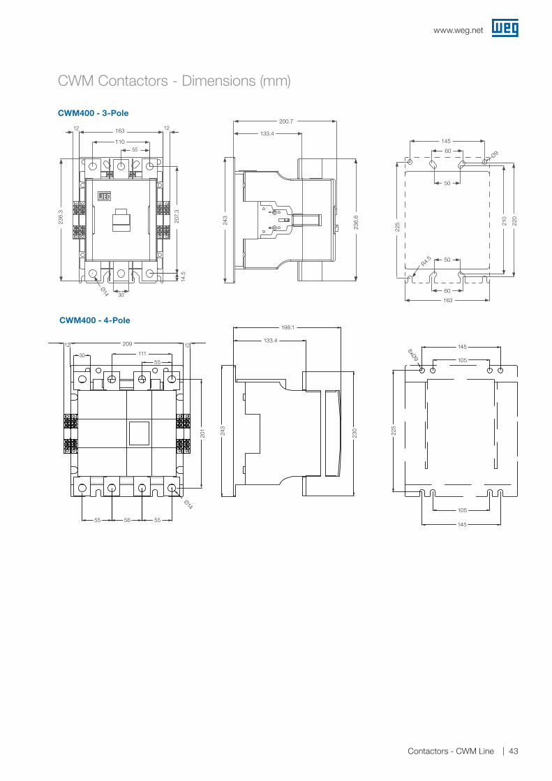
CWM400 - 3-Pole
Ø14
207,3
243
236,6
145
225
50
60
210
220
60
50
30163
55110
163
200,7
133,4
R4,5
Ø9
12 12
236,3
14,5
CWM Contactors - Dimensions (mm)
CWM400 - 4-Pole
201
55 56 55
Ø14
30
243
105
145
8xØ9
225
105
145
55
111
209
230
198,1
133,41212
145
145
105
225
105
8xØ9
Ø14
Ø9
Ø1423
0
201
207.
3
243
236.
6
225 21
0
220
14.5
236.
3
55
56
209
111
55 55
243
133.4
198.1
1212 209
163
145
163
R4.5
60
60
50
50
200.7
110133.4
12
12
30
12
12
55
30
www.weg.net
43Contactors - CWM Line
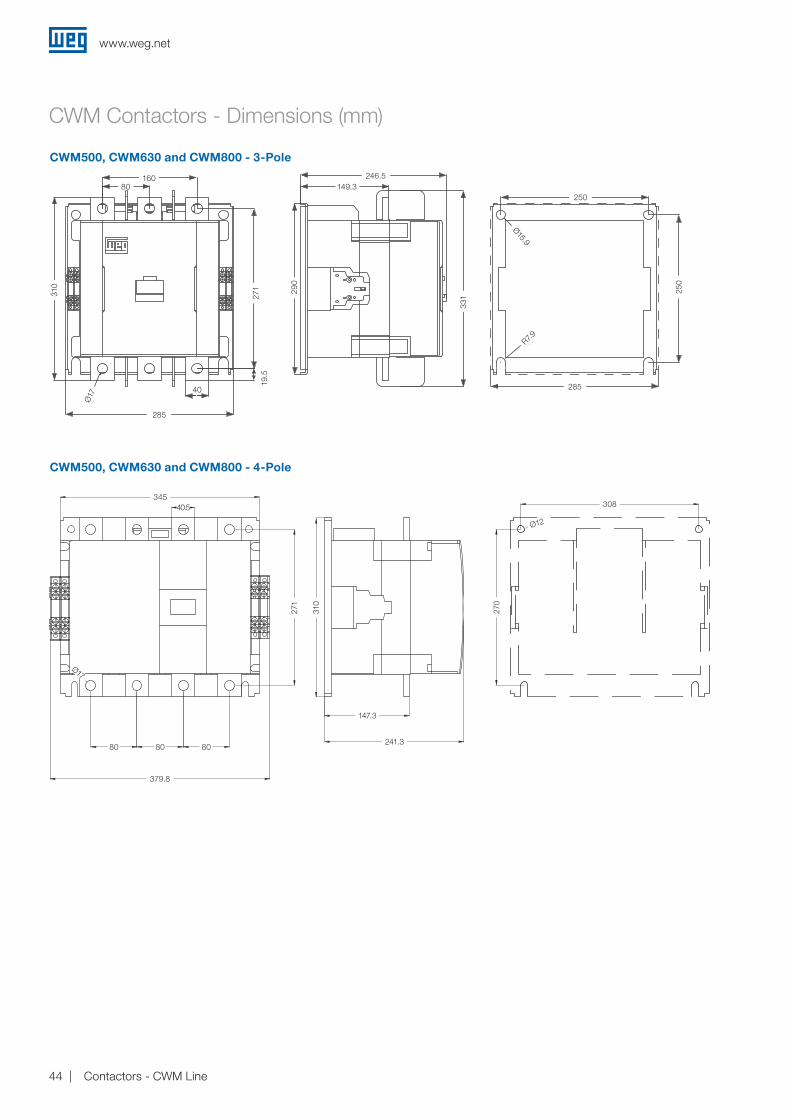
CWM500, CWM630 and CWM800 - 3-Pole
80 80 80
271
310
147,3
241,3
379,8
308
270
12
17
345
40,5
80
379.8
345308
271
310
270
40.5
80 80241.3
147.3
Ø12
Ø17
CWM Contactors - Dimensions (mm)
CWM500, CWM630 and CWM800 - 4-Pole
80160
Ø17 40
271 290
Ø 15,9
250
285
331
149,3
285
246,5
310
R7,9
19,5
285
160 246.5
250
285
250
80 149.3
40
19.5
310
271 29
0
331
Ø17
Ø15.9
R7.9
L
J
I
H
G
F
E
D
C
B
A
1 2 3 4 5 6 7 8 9 10 11 12 13 14 15 16
mm [inches]Escala 1:1 A001/09/2011
2 x CWM500...800 + BLIM CWME800
Sujeit
o a alt
eração
sem a
viso p
révio.
As inf
ormaçõ
es con
tidas
são va
lores
de re
ferênc
ia.
Lo
s valo
res de
mostra
dos p
ueden
ser ca
mbiad
os sin
aviso
previ
o. La in
forma
ción é
s de re
ferenc
ia sola
mente
.Th
e valu
es sho
wn ar
e sub
ject to
chan
ge wi
thout
prior
notic
e. The
inform
ation
is for
refer
ence
only.
A
F
E
B
23.5
D
C
75
www.weg.net
44 Contactors - CWM Line
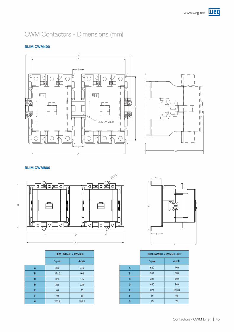
BLIM CWM400
CWM Contactors - Dimensions (mm)
BLIM CWM800
BLIM CWM400 + CWM400
3-pole 4-pole
A 330 375
B 371.2 464
C 330 375
D 225 225
E 40 85
F 40 85
G 203.9 198.2
BLIM CWM800 + CWM500...800
3-pole 4-pole
A 680 740
B 351 370
C 321 340
D 440 440
E 321 316.3
F 86 86
G 75 75
BLIM CWM400
B
C
E
E
BLIN CWM400
AG
D
L
J
I
H
G
F
E
D
C
B
A
1 2 3 4 5 6 7 8 9 10 11 12 13 14 15 16
mm [inches]Escala 1:1 A001/09/2011
2 x CWM500...800 + BLIM CWME800
Sujeit
o a alt
eração
sem a
viso p
révio.
As inf
ormaçõ
es con
tidas
são va
lores
de re
ferênc
ia.
Lo
s valo
res de
mostra
dos p
ueden
ser ca
mbiad
os sin
aviso
previ
o. La in
forma
ción é
s de re
ferenc
ia sola
mente
.Th
e valu
es sho
wn ar
e sub
ject to
chan
ge wi
thout
prior
notic
e. The
inform
ation
is for
refer
ence
only.
A
F
E
B
23.5
D
C
75Ø23.575
E
F
B
A
D
C
www.weg.net
45Contactors - CWM Line

CWM Contactors - Dimensions (mm)
BMP CWM400...800
BMJ CWM400...800
CWM400...800
Mounting Position
BMP CWM400+
CWM400
BMP CWM800+
CWM500...800
3-pole 4-pole 3-pole 4-pole
A 148.8 214 234 314
B 248.2 250.8 320.2 350.5
C 200.7 198.2 246.5 241.3
D 2.6 1.76 111.6 20.25
E 2.6 7.76 15.1 20.25
E
A
EDE
B
A C
50
30°30°30°30°30°30°30°30°
50
BMJ CWM400+
CWM400
BMJ CWM800+
CWM500...800
A 140.2 202
B 55 80
C 30.2 42
D 187.4 199.15
E 53.6 74.65
F 59.5 65.7
G 350.2 439.3
C
B F
D
H
E
A
E
H
G
BD
F
C
www.weg.net
46 Contactors - CWM Line

Global presence is essential, as much as understanding your needs.
Global PresenceWith more than 30.000 employees worldwide, WEG is one of the largest electric motors, electronic equipments and systems manufacturers. We are constantly expanding our portfolio of products and services with expertise and market knowledge. We create integrated and customized solutions ranging from innovative products to complete after-sales service.
WEG’s know-how guarantees our Contactors - CWM Line is the right choice for your application and business, assuring safety, efficiency and reliability.
Partnership is to create solutions that suits your needs
Competitive edge is to unite technology and inovation
Availability is to have a global support network
Excelence is to provide a whole solution in industrial automation that improves our customers productivity.
High performance and reliable products to improve your production process.
Know More
youtube.com/wegvideosVisit: www.weg.net
47Contactors - CWM Line
WEG Worldwide Operations
WEG Group - Automation Business Unit Jaraguá do Sul - SC - Brazil Phone: +55 47 3276 4000 [email protected] www.weg.net C
od: 5
007
0163
| R
ev: 0
0 | D
ate
(m/y
): 11
/201
6Th
e va
lues
sho
wn
are
sub
ject
to c
hang
e w
ithou
t prio
r no
tice.
For those countries where there is not a WEG own operation, find our local distributor at www.weg.net.
ARGENTINASan Francisco - CordobaPhone: +54 3564 [email protected]
Cordoba - CordobaPhone: +54 351 [email protected]
Buenos AiresPhone: +54 11 [email protected]
AUSTRALIAScoresby - Victoria Phone: +61 3 [email protected]
AUSTRIAMarkt Piesting - Wiener Neustadt-LandPhone: +43 2633 [email protected]
BELGIUMNivelles - BelgiumPhone: +32 67 [email protected]
BRAZILJaraguá do Sul - Santa CatarinaPhone: +55 47 [email protected]
CHILELa Reina - SantiagoPhone: +56 2 [email protected]
CHINANantong - JiangsuPhone: +86 513 [email protected]
Changzhou – Jiangsu Phone: +86 519 [email protected]
COLOMBIASan Cayetano - BogotaPhone: +57 1 [email protected]
ECUADOREl Batan - QuitoPhone: +593 2 [email protected]
FRANCESaint-Quentin-Fallavier - IsèrePhone: +33 4 [email protected]
GERMANYTürnich - Kerpen Phone: +49 2237 [email protected]
Balingen - Baden-WürttembergPhone: +49 7433 [email protected]
Homberg (Efze) - HessePhone: +49 5681 [email protected]
GHANAAccraPhone: +233 30 [email protected]
INDIABangalore - KarnatakaPhone: +91 80 [email protected]
Hosur - Tamil NaduPhone: +91 4344 [email protected]
ITALYCinisello Balsamo - MilanoPhone: +39 2 [email protected]
JAPANYokohama - KanagawaPhone: +81 45 [email protected]
MALAYSIAShah Alam - SelangorPhone: +60 3 [email protected]
MEXICOHuehuetoca - MexicoPhone: +52 55 [email protected]
Tizayuca - HidalgoPhone: +52 77 97963790
NETHERLANDSOldenzaal - OverijsselPhone: +31 541 [email protected]
PERULa Victoria - LimaPhone: +51 1 [email protected]
PORTUGALMaia - PortoPhone: +351 22 [email protected]
RUSSIA and CISSaint PetersburgPhone: +7 812 363 [email protected]
SOUTH AFRICAJohannesburgPhone: +27 11 [email protected]
SPAINCoslada - MadridPhone: +34 91 [email protected]
SINGAPORESingaporePhone: +65 [email protected]
SingaporePhone: +65 [email protected]
SCANDINAVIAMölnlycke - SwedenPhone: +46 31 [email protected]
UKRedditch - WorcestershirePhone: +44 1527 [email protected]
UNITED ARAB EMIRATESJebel Ali - DubaiPhone: +971 4 [email protected]
USADuluth - GeorgiaPhone: +1 678 [email protected]
Minneapolis - MinnesotaPhone: +1 612 3788000
VENEZUELAValencia - CaraboboPhone: +58 241 [email protected]