automatic plant irrigation system report
DESCRIPTION
to reduce the manpower using technology.and also to asure that water and electricity should not be wasted.TRANSCRIPT

AUTOMATIC PLANT IRRIGATION SYSTEM
A PROJECT REPORT
SUBMITTED TO-
ELECTRICAL DEPARTMENT OF
GYAN GANGA INSTITUTE OF TECHNOLOGY AND SCIENCES
JABALPUR
Submitted by-
SUMIT KUMAR
ABHISHEK GARG
SHIVENDRA SINGH
KANIKA VISHWAKARMA
SHIVANGI RAJPUT
ABHAY KUMAR BURMAN
CERTIFICATE OF APPROVAL
The foregoing project work report entitled “AUTOMATIC PLANT
IRRIGATION SYSTEM” is a hereby approved as a creditable work
and has been presented in a satisfactory manner to warrant its acceptance
as prerequisite to the degree for which it has been submitted.
It is understood that for this approval, the undersigned do not
necessarily endorse any conclusion drawn or opinion expressed therein,
but approve the project work for the purpose for which it is submitted.
(INTERNAL EXAMINEER) (EXTERNAL EXAMINEER)
(HEAD OF THE DEPARTMENT)

GYAN GANGA INSTITUTE OF TECHNOLOGY AND SCIENCES
JABALPUR
CERTIFICATE
This is to certify that the work presented in the project report entitled
“AUTOMATIC PLANT IRRIGATION SYSTEM” in the partial
fulfillment of the requirement for the award of Degree of Bachelor of
Engineering in Electrical of The Gyan Ganga Institute Of Technology
And Sciences, JABALPUR is an authentic work carried out under my
supervision and guidance.
Date:
Miss. Jasmine Kaur Mr. S.K. Bajpai
(Project Guide) (Head of the Department)
ACKNOWLEDGEMENT
Knowledge is an experience gained in life. It is the choicest possession, which should not be shelved but should be happily shared with others. In this regard We are extremely fortunate in having Miss. Jasmine Kaur as our project guide .It was she, who provided proper direction in the completion of this project work. Her willingness to share her experience and spontaneous suggestion on any problem encourage us tremendously to achieve our goal .We are sure her directive will show us the light in future also. We are very much thankful to Mr. S. K. Bajpai, HOD, EE department for his encouragement, valuable suggestion and moral support provided by him and helped in every way possible during the completion of this project.
Sumit Kumar Abhishek GargShivendra SinghKanika VishwakarmaShivangi RajputAbhay Kumar Burman
TABLE OF CONTENT
1) INTRODUCTION
2) WORKING
- CIRCUIT DIAGRAM
- CIRCUIT DISCRIPTION
- COMPONENT LIST
- COMPONENT DISCRIPTION
3) PROCEDURE ADOPTED
- PCB DESIGNING - COMPONENT MOUNTED ON PCB
- SOFTWARE USED
4) APPLICATIONS
5) REFRENCE
INTRODUCTION

In the fast paced world human beings require everything to be automated. Our life style demands everything to be remote controlled. Apart from few things man has made his life automated .And why not? In the world of advance electronics, life of human beings should be simpler hence to make life simpler and convenient; we have made “AUTOMATIC PLANT IRRIGATION SYSTEM”. A model of controlling irrigation facilities to help millions of people. This model uses sensor technology with NE 555 IC to make a smart switching device.
The model shows the basic switching mechanism of Water motor/pump using sensors from any part of field by sensing the moisture present in the soil. Our basic model can be extended to any level of switching & controlling by using DTMF.
WORKING

CIRCUIT DIAGRAM-
1) BASIC DIAGRAM-
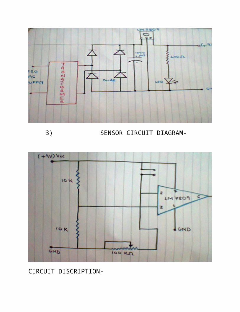
2) POWER SUPPLY CIRCUIT-
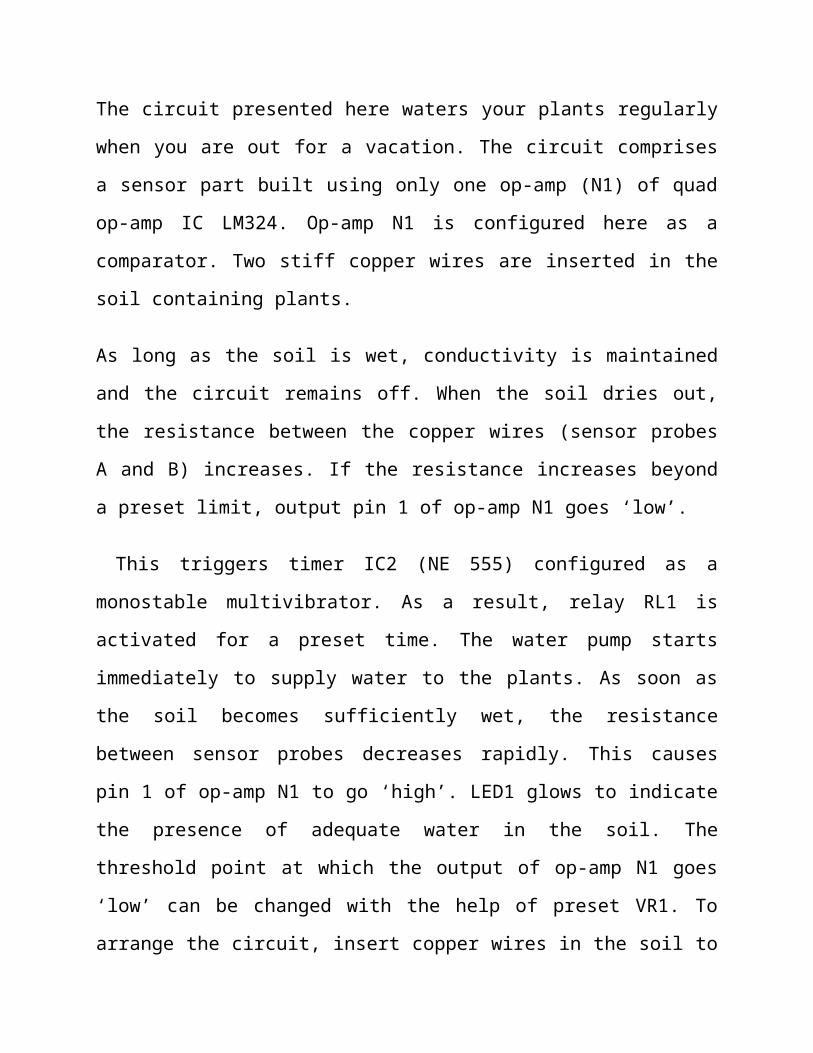
3) SENSOR CIRCUIT DIAGRAM-
CIRCUIT DISCRIPTION-
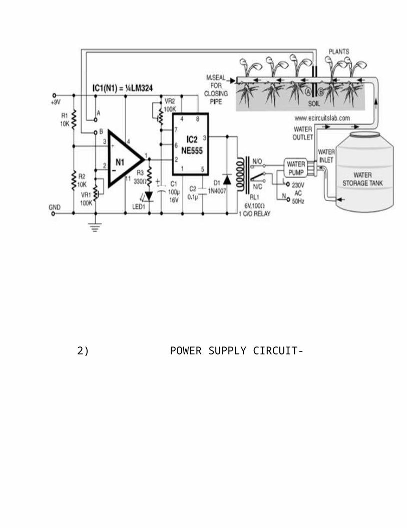
The circuit presented here waters your plants regularly when you are out
for a vacation. The circuit comprises a sensor part built using only one op-
amp (N1) of quad op-amp IC LM324. Op-amp N1 is configured here as a
comparator. Two stiff copper wires are inserted in the soil containing plants.
As long as the soil is wet, conductivity is maintained and the circuit remains
off. When the soil dries out, the resistance between the copper wires
(sensor probes A and B) increases. If the resistance increases beyond a
preset limit, output pin 1 of op-amp N1 goes ‘low’.
This triggers timer IC2 (NE 555) configured as a monostable multivibrator.
As a result, relay RL1 is activated for a preset time. The water pump starts
immediately to supply water to the plants. As soon as the soil becomes
sufficiently wet, the resistance between sensor probes decreases rapidly.
This causes pin 1 of op-amp N1 to go ‘high’. LED1 glows to indicate the
presence of adequate water in the soil. The threshold point at which the
output of op-amp N1 goes ‘low’ can be changed with the help of preset
VR1. To arrange the circuit, insert copper wires in the soil to a depth of
about 2 cm, keeping them 3 cm apart. When the soil the water. LED1 glows
up as the water reaches the probes.
For small areas a small pump such as the one used in air coolers is able to
pump enough water within 5 to 6 seconds. The timing components for IC2
are selected accordingly. The timing can be varied with the help of preset
VR2. The circuit is more effective indoors if one intends to use it for long
periods. This is because the water from reservoir (bucket, etc) evaporates
rapidly if it is kept in the open. For regulating the flow of water either a tap
can be used or one end of a rubber pipe can be blocked using Mseal
compound, with holes gets dried, adjust VR1 towards ground rail until
LED1 turns off and relay RL1 is energized. The motor starts pumping
turned along its length to water several plants.
LIST OF COMPONENT USED-
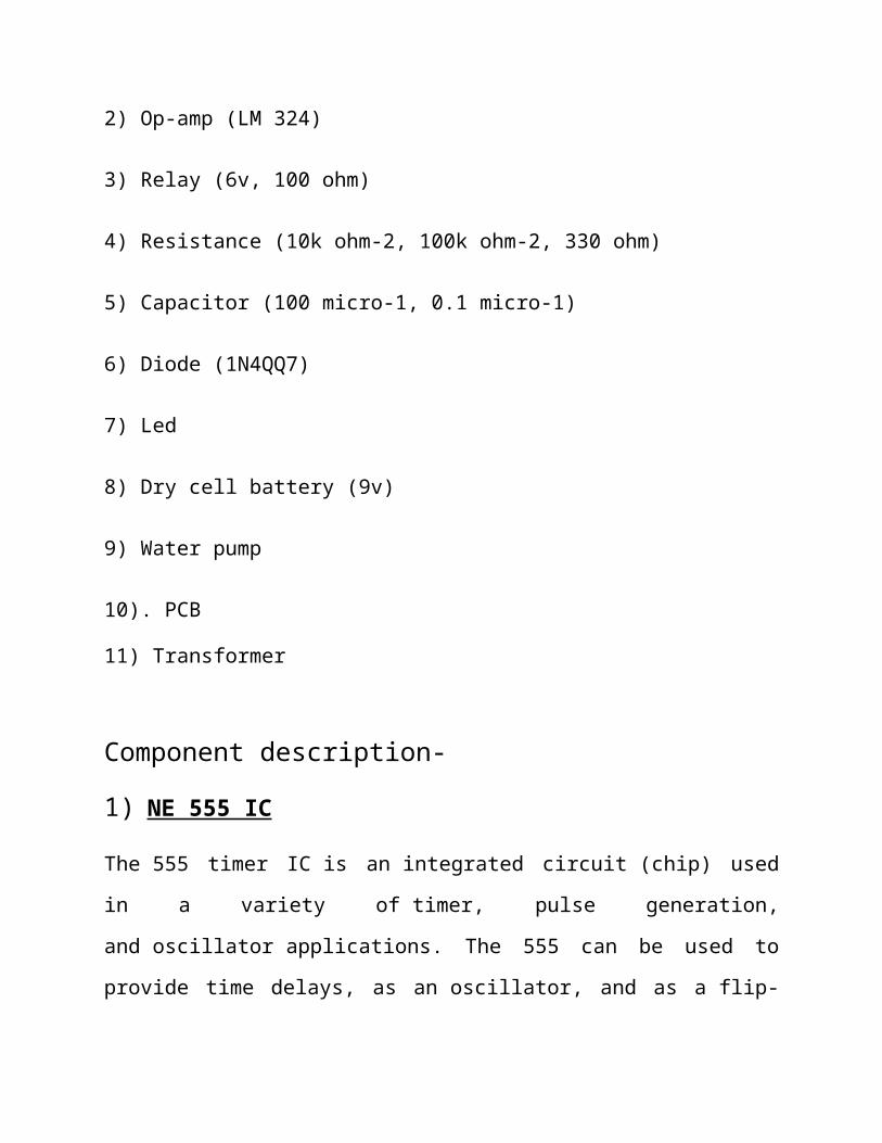
1) IC NE 555
2) Op-amp (LM 324)
3) Relay (6v, 100 ohm)
4) Resistance (10k ohm-2, 100k ohm-2, 330 ohm)
5) Capacitor (100 micro-1, 0.1 micro-1)
6) Diode (1N4QQ7)
7) Led
8) Dry cell battery (9v)
9) Water pump
10). PCB
11) Transformer
Component description-
1) NE 555 IC
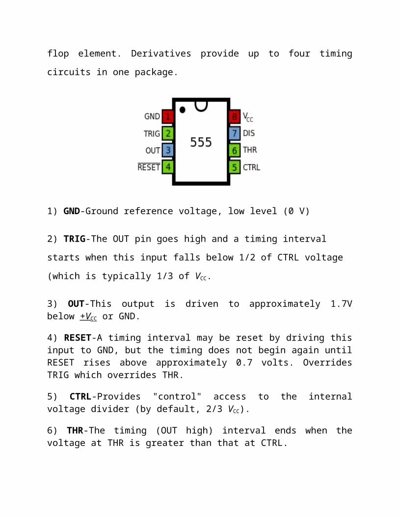
The 555 timer IC is an integrated circuit (chip) used in a variety of timer,
pulse generation, and oscillator applications. The 555 can be used to
provide time delays, as an oscillator, and as a flip-flop element. Derivatives
provide up to four timing circuits in one package.
1) GND-Ground reference voltage, low level (0 V)
2) TRIG-The OUT pin goes high and a timing interval starts when this input
falls below 1/2 of CTRL voltage (which is typically 1/3 of VCC.
3) OUT-This output is driven to approximately 1.7V below + V CC or GND.
4) RESET-A timing interval may be reset by driving this input to GND, but the timing does not begin again until RESET rises above approximately 0.7 volts. Overrides TRIG which overrides THR.
5) CTRL-Provides "control" access to the internal voltage divider (by default, 2/3 VCC).
6) THR-The timing (OUT high) interval ends when the voltage at THR is greater than that at CTRL.
7) DIS-Open collector output which may discharge a capacitor between intervals.
8) VCC-Positive supply voltage, which is usually between 3 and 15 V depending on the variation.

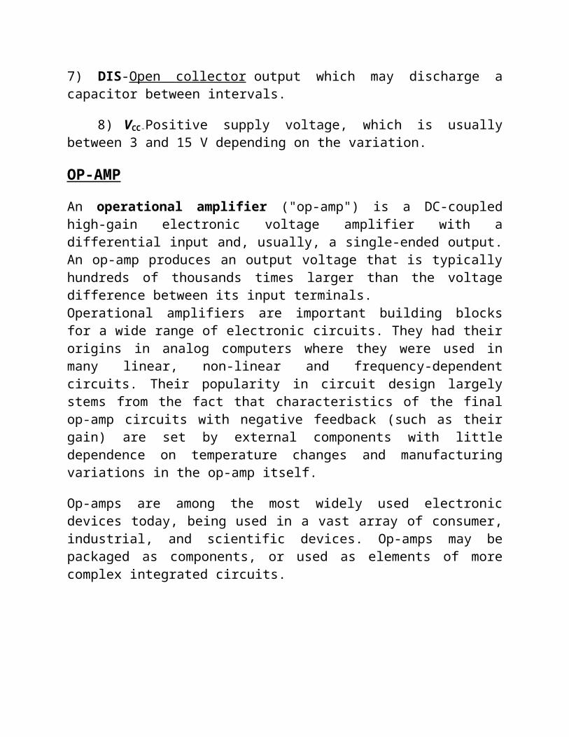
OP-AMP
An operational amplifier ("op-amp") is a DC-coupled high-gain electronic voltage amplifier with a differential input and, usually, a single-ended output. An op-amp produces an output voltage that is typically hundreds of thousands times larger than the voltage difference between its input terminals. Operational amplifiers are important building blocks for a wide range of electronic circuits. They had their origins in analog computers where they were used in many linear, non-linear and frequency-dependent circuits. Their popularity in circuit design largely stems from the fact that characteristics of the final op-amp circuits with negative feedback (such as their gain) are set by external components with little dependence on temperature changes and manufacturing variations in the op-amp itself.
Op-amps are among the most widely used electronic devices today, being used in a vast array of consumer, industrial, and scientific devices. Op-amps may be packaged as components, or used as elements of more complex integrated circuits.
RELAY
The electromagnetic relay consists of a multi-turn coil, wound on an iron core, to form an electromagnet. When the coil is energized, by passing current through it, the core becomes temporarily magnetized. The
magnetized core attracts the iron armature. The armature is pivoted which causes it to operate one or more sets of contacts. When the coil is de-energized the armature and contacts are released. The coil can be energized from a low power source such as a transistor while the contacts can switch high powers such as the mains supply. The relay can also be situated remotely from the control source. Relays can generate a very high voltage across the coil when switched off. This can damage other components in the circuit. To prevent this a diode is connected across the coil.
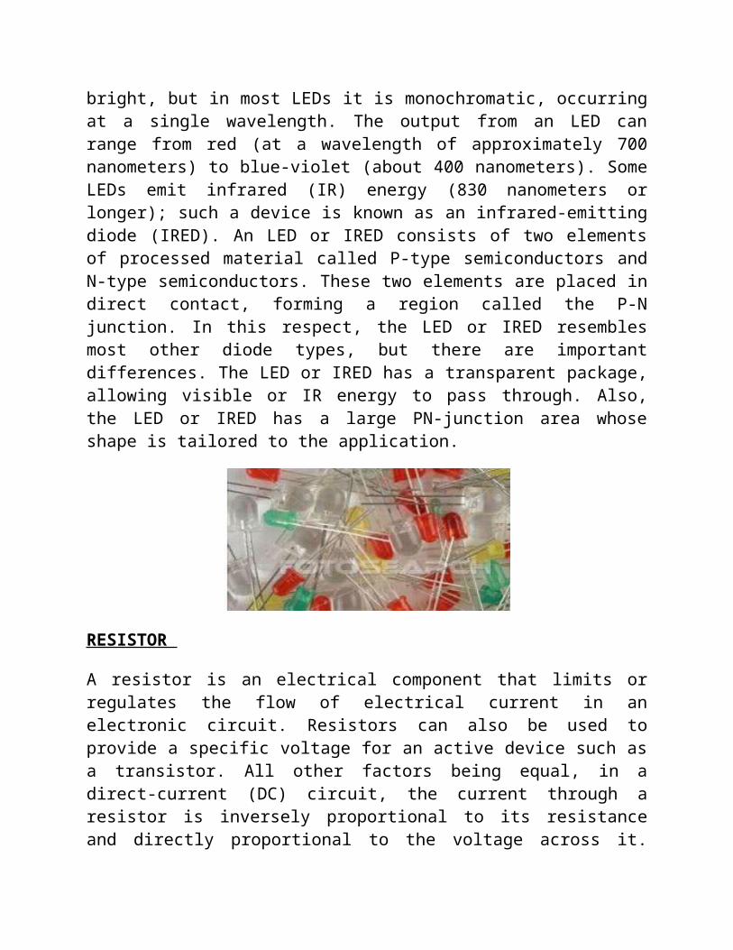
LED
A light-emitting diode (LED) is a semiconductor device that emits visible light when an electric current passes through it. The light is not particularly bright, but in most LEDs it is monochromatic, occurring at a single wavelength. The output from an LED can range from red (at a wavelength of approximately 700 nanometers) to blue-violet (about 400 nanometers). Some LEDs emit infrared (IR) energy (830 nanometers or longer); such a device is known as an infrared-emitting diode (IRED). An LED or IRED consists of two elements of processed material called P-type semiconductors and N-type semiconductors. These two elements are placed in direct contact, forming a region called the P-N junction. In this respect, the LED or IRED resembles most other diode types, but there are important differences. The LED or IRED has a transparent package, allowing visible or IR energy to pass through. Also, the LED or IRED has a large PN-junction area whose shape is tailored to the application.
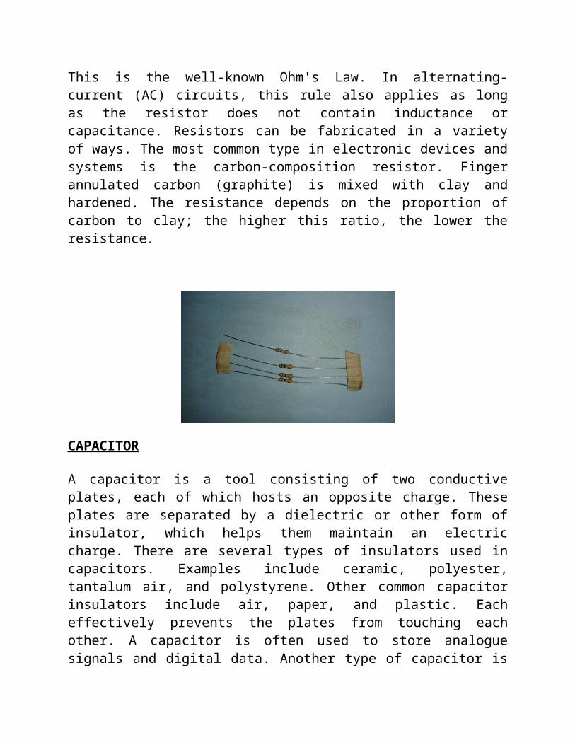
RESISTOR
A resistor is an electrical component that limits or regulates the flow of electrical current in an electronic circuit. Resistors can also be used to provide a specific voltage for an active device such as a transistor. All other
factors being equal, in a direct-current (DC) circuit, the current through a resistor is inversely proportional to its resistance and directly proportional to the voltage across it. This is the well-known Ohm's Law. In alternating-current (AC) circuits, this rule also applies as long as the resistor does not contain inductance or capacitance. Resistors can be fabricated in a variety of ways. The most common type in electronic devices and systems is the carbon-composition resistor. Finger annulated carbon (graphite) is mixed with clay and hardened. The resistance depends on the proportion of carbon to clay; the higher this ratio, the lower the resistance.
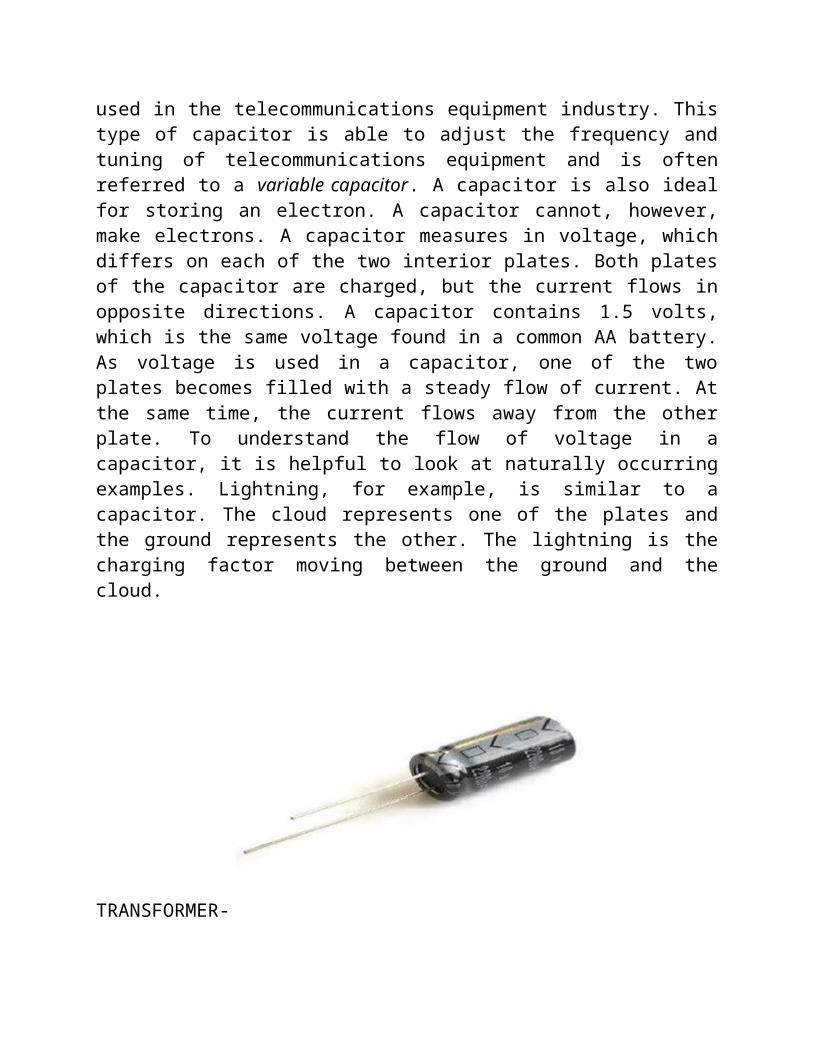
CAPACITOR A capacitor is a tool consisting of two conductive plates, each of which hosts an opposite charge. These plates are separated by a dielectric or other form of insulator, which helps them maintain an electric charge. There are several types of insulators used in capacitors. Examples include ceramic, polyester, tantalum air, and polystyrene. Other common capacitor insulators include air, paper, and plastic. Each effectively prevents the plates from touching each other. A capacitor is often used to store analogue signals and digital data. Another type of capacitor is used in the telecommunications equipment industry. This type of capacitor is able to adjust the frequency and tuning of telecommunications equipment and is often referred to a variable capacitor. A capacitor is also ideal for storing an electron. A capacitor cannot, however, make electrons. A capacitor measures in voltage, which differs on each of the two interior plates. Both plates of the capacitor are charged, but the current flows in opposite directions. A capacitor contains 1.5 volts, which is the same voltage found in a common AA battery. As voltage is used in a capacitor, one of the two plates becomes filled with a steady flow of current. At the same time, the
current flows away from the other plate. To understand the flow of voltage in a capacitor, it is helpful to look at naturally occurring examples. Lightning, for example, is similar to a capacitor. The cloud represents one of the plates and the ground represents the other. The lightning is the charging factor moving between the ground and the cloud.
TRANSFORMER-
Power supply is a reference to a source of electrical power. A device or system that supplies electrical or other types of energy to an output load or group of loads is called a power supply unit or PSU. The term is most commonly applied to electrical energy supplies, less often to mechanical ones, and rarely to others. Here in our application we need a 9v DC power supply for all electronics involved in the project. This requires step down transformer, rectifier, voltage regulator, and filter circuit for generation of 9v of power.
PROCEDURE ADOPTED
PCB DESIGNING-
STEPS TO DESIGN PCB
1. LAYOUT PREPARATION
Prepare the layout of the circuit diagram using the software.
Take the print out of the layout on transparent sheet or butter paper in inverted format.
2. LAYOUT IMPRESSION ON CLAD BORD
Take the impression of layout on clad board using carbon paper or electric iron.
3. ETCHING
Now dip the clad board having printed layout into the etch solution.
The etch solution removes the unwanted copper.
Now we are able to get the required layout printed on PCB in the form of copper.
4. TESTING
Now test the tracks using multimeter.
5. DRILLING/PUNCHING
Now drill the required holes for component mounting
LAYOUT
TOOLS USED TO MOUNT THE COMPONENT ON YHE PCB
Soldering iron
A soldering iron is a hand tool most commonly used in soldering. It supplies heat to melt the solder so that it can flow into the joint between two work pieces. A soldering iron is composed of a heated metal tip and an insulated handle. Heating is often achieved electrically, by passing an electric current (supplied through an electrical cord or battery cables) through the resistive material of a heating element. Another heating method includes combustion of a suitable gas, which can either be delivered through a tank mounted on the iron (flameless), or through an external flame. Less common uses include pyrography (burning designs into wood) and plastic welding. Soldering irons are most often used for installation, repairs, and limited production work. High-volume production lines use other soldering methods.
Wire Stripper
Wire stripper is used to strip off wire insulator from its conductor before it is used to connect to another wire or soldered into the printed circuit board. Some wire stripper or wire cutter has a measurement engraved on it to indicate the length that will be stripped.
Side-Cutting Pliers
A 4-inch side cutting pliers will come in handy as one of the electronic tools when one need to trim off excess component leads on the printed circuit board. It can also be used to cut wires into shorter length before being used. Tweezers Small tweezers is used to hold small components especially when doing soldering and de-soldering of surface mount components.