auto tonometerdoclibrary.com/msc167/prm/16050-101-rev-k-ug3835.pdfno part of this publication may be...
TRANSCRIPT
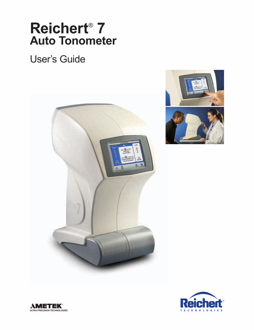
Reichert® 7Auto Tonometer User’s Guide
©2016 AMETEK, Inc.
Reichert and Reichert Technologies are registered trademarks of Reichert, Inc.
AMETEK is a registered trademark of AMETEK, Inc.
All other trademarks are property of their respective owners.
The information contained in this document was accurate at time of publication. Specifications subject to change without notice. Reichert, Inc. reserves the right to make changes in the product described in this manual without notice and without incorporating those changes in any products already sold.
ISO 9001/13485 Certified – Reichert products are designed and manufactured under quality processes meeting ISO 9001/13485 requirements.
No part of this publication may be reproduced, stored in a retrieval system, or transmitted in any form or by any means, electronic, mechanical, recording, or otherwise, without the prior written permission of Reichert, Inc.
Caution: Federal law restricts this device to sale by or on the order of a licensed physician. Rx only.
16050-101 Rev. K 3
Contents
Warnings & Cautions ....................................................................................... 4 Symbols ........................................................................................................... 6 Introduction ...................................................................................................... 7
Indications for Use ..................................................................................... 7 Contraindications ....................................................................................... 7
Instrument Setup ............................................................................................... 8 Unpacking Instructions .............................................................................. 8 Shipping Protector ..................................................................................... 8 Application of Input Power ......................................................................... 9 Disconnection of Input Power .................................................................... 9 PartsIdentification ................................................................................... 10 Accessories ............................................................................................. 10
IconDefinition .......................................................................................... 11 Default Settings ....................................................................................... 12
Customized Options .......................................................................... 13 Tonometer Settings .................................................................................. 14 Printout Settings ...................................................................................... 15 Communication Settings .......................................................................... 16 General Settings ...................................................................................... 17
Instructions for Use ..........................................................................................18 Alignment and Measurement ................................................................... 18 Demo Puff ................................................................................................ 23 LowConfidenceReadings ....................................................................... 24 Too Far Activated ..................................................................................... 26Printing Measurement Data ..................................................................... 27
Cleaning & Maintenance ................................................................................. 28 Fuses ....................................................................................................... 28 External Cleaning .................................................................................... 28Forehead Rest Cleaning .......................................................................... 28 Operator Display Cleaning ...................................................................... 28Printer Paper ............................................................................................ 28 Positioning Windows and Airtube Cleaning ............................................. 29Forehead Rest Pad Replacement ........................................................... 30
Troubleshooting ................................................................................................31 Help Screens ........................................................................................... 31 Chart of Common Errors ........................................................................ 32 Print-Related Errors ................................................................................. 33
Specifications .................................................................................................. 34Classifications ................................................................................................. 35Guidance Tables ............................................................................................ 36Warranty ........................................................................................................ 39
16050-101 Rev. K4
Reichert Technologies® is not responsible for the safety and reliability of this instrument when:
•Assembly,disassembly,repair,ormodificationismadebyunauthorizeddealersorpersons.• Instrument is not used in accordance with this User’s Guide.
WARNING: AN INSTRUCTION THAT DRAWS ATTENTION TO RISK OF INJURY OR DEATH.
WARNING: UNITED STATES FEDERAL LAW AND EUROPEAN REGULATIONS REQUIRE THAT THIS DEVICE BE PURCHASED ONLY BY A PHYSICIAN OR A PERSON ACTING ON BEHALF OF A PHYSICIAN.
WARNING: THIS INSTRUMENT SHOULD BE USED IN STRICT ACCORDANCE WITH THE INSTRUCTIONS OUTLINED IN THIS USER’S GUIDE. THE SAFETY OF THE OPERATOR AND THE PERFORMANCE OF THE INSTRUMENT CANNOT BE GUARANTEED IF USED IN A MANNER NOT SPECIFIED BY REICHERT TECHNOLOGIES.
WARNING: DO NOT REPAIR OR SERVICE THIS INSTRUMENT WITHOUT AUTHORIZATION FROM THE MANUFACTURER. ANY REPAIR OR SERVICE TO THIS INSTRUMENT MUST BE PERFORMED BY EXPERIENCED PERSONNEL OR DEALERS WHO ARE TRAINED BY REICHERT OR SERIOUS INJURY TO THE OPERATOR OR PATIENT MAY OCCUR.
WARNING: MODIFICATIONS TO THIS INSTRUMENT ARE NOT ALLOWED. ANY MODIFICATION TO THIS UNIT MUST BE AUTHORIZED BY REICHERT OR SERIOUS INJURY TO THE OPERATOR OR PATIENT MAY OCCUR.
WARNING: IF THIS INSTRUMENT IS MODIFIED, APPROPRIATE INSPECTION AND TESTING MUST BE CONDUCTED TO ENSURE CONTINUED SAFE USE OF THIS INSTRUMENT.
WARNING: TO AVOID RISK OF ELECTRIC SHOCK, THIS EQUIPMENT MUST ONLY BE CONNECTED TO A SUPPLY MAINS WITH PROTECTIVE EARTH OR DAMAGE TO THIS INSTRUMENT AND/OR INJURY TO THE OPERATOR OR PATIENT MAY OCCUR.
WARNING: ENSURE THAT THE VOLTAGE APPLIED TO THE UNIT IS THE SAME AS THE VOLTAGE THAT IS INDICATED ON THE DATA PLATE OR DAMAGE TO THE INSTRUMENT AND/OR INJURY TO THE OPERATOR OR PATIENT MAY OCCUR.
WARNING: THIS INSTRUMENT MUST BE PLUGGED INTO AN OUTLET WITH AN EARTH GROUND. DO NOT REMOVE OR DEFEAT THE EARTH GROUND CONNECTION ON POWER INPUT CONNECTOR OR THE UNIT’S POWER CORD OF THIS INSTRUMENT OR DAMAGE TO IT AND/OR INJURY TO THE OPERATOR OR PATIENT MAY OCCUR.
WARNING: THE EQUIPMENT OR SYSTEM SHOULD NOT BE USED ADJACENT TO OR STACKED WITH OTHER EQUIPMENT AND THAT IF ADJACENT OR STACKED USE IS NECESSARY, THE EQUIPMENT OR SYSTEM SHOULD BE OBSERVED TO VERIFY NORMAL OPERATION IN THE CONFIGURATION IN WHICH IT WILL BE USED.
WARNING: THIS INSTRUMENT IS NOT SUITABLE FOR USE IN THE PRESENCE OF FLAMMABLE ANESTHETIC MIXTURES, SUCH AS OXYGEN OR NITROUS OXIDE.
WARNING: DO NOT PLACE FINGERS INTO THE OPENING SURROUNDING THE NOSEPIECE.
Warnings & Cautions
16050-101 Rev. K 5
Warnings & Cautions (continued)
CAUTION: AN INSTRUCTION THAT DRAWS ATTENTION TO THE RISK OF DAMAGE TO THE PRODUCT.
CAUTION: THE INTERNAL CIRCUITRY OF THE INSTRUMENT CONTAINS ELECTROSTATIC DISCHARGE SENSITIVE DEVICES (ESDS) THAT MAY BE SENSITIVE TO STATIC CHARGES PRODUCED BY THE HUMAN BODY. DO NOT REMOVE THE COVERS WITHOUT TAKING PROPER PRECAUTIONS.
CAUTION: THIS INSTRUMENT IS NOT INTENDED TO BE CONNECTED TO EQUIPMENT OUTSIDE THE CONTROL OF REICHERT TECHNOLOGIES OR MUST BE TESTED TO AN APPLICABLE IEC OR ISO STANDARDS.
CAUTION: DO NOT USE SOLVENTS OR STRONG CLEANING SOLUTIONS ON ANY PART OF THIS INSTRUMENT AS DAMAGE TO THE UNIT MAY OCCUR. SEE MAINTENANCE SECTION FOR DETAILED CLEANING INSTRUCTION.
CAUTION: USE OF AMMONIA BASED CLEANERS ON THE LIQUID CRYSTAL DISPLAY (LCD) MAY CAUSE DAMAGE TO THE DISPLAY. SEE MAINTENANCE SECTION FOR DETAILED CLEANING INSTRUCTION.
CAUTION: MEDICAL ELECTRONIC EQUIPMENT NEEDS SPECIAL PRECAUTIONS REGARDING EMC AND NEEDS TO BE INSTALLED AND PUT INTO SERVICE ACCORDING TO THE EMC INFORMATION PROVIDED IN THE ACCOMPANYING DOCUMENTS.
CAUTION: PORTABLE AND MOBILE RF COMMUNICATIONS EQUIPMENT CAN AFFECT MEDICAL ELECTRICAL EQUIPMENT.
CAUTION: THIS INSTRUMENT IS NOT TO BE USED NEAR HIGH-FREQUENCY EMITTING SURGICAL EQUIPMENT.
16050-101 Rev. K6
Symbols
Symbol Information
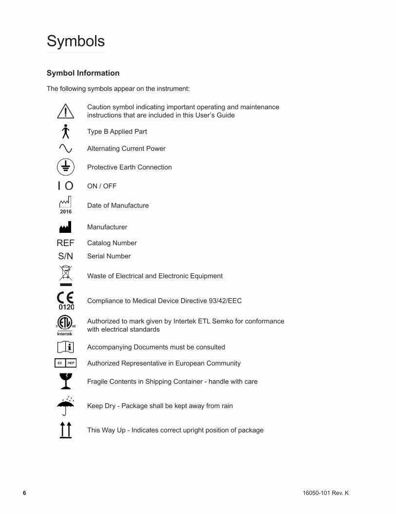
The following symbols appear on the instrument:
Caution symbol indicating important operating and maintenance instructions that are included in this User’s Guide
Type B Applied Part
Alternating Current Power
Protective Earth Connection
ON / OFF
2016Date of Manufacture
Manufacturer
REF Catalog Number
S/N Serial Number
Waste of Electrical and Electronic Equipment
Compliance to Medical Device Directive 93/42/EEC
Authorized to mark given by Intertek ETL Semko for conformance with electrical standards
Accompanying Documents must be consulted
Authorized Representative in European Community
Fragile Contents in Shipping Container - handle with care
Keep Dry - Package shall be kept away from rain
This Way Up - Indicates correct upright position of package
16050-101 Rev. K 7
Introduction
Congratulations on your purchase of the Reichert® 7 Auto Tonometer.
The Reichert 7 is an auto-aligning, non-contact tonometer used to measure the intraocular pressure of the eye by delivering a very soft air puff or puffs to the eye.
This User’s Guide is designed as a training and reference manual for operation, maintenance, and troubleshooting. We recommend that you read it carefully prior to use and follow the instructions in the guide to ensure optimum performance of your new instrument. Properly trained eyecare professionals such as ophthalmologists, optometrists, opticians and eye care technicians should operate this instrument.
Please retain this guide for future reference and to share with other users. Additional copies can be obtained from your authorized Reichert Technologies dealer or contact our Customer Service department directly at:
Tel: 716-686-4500 Fax: 716-686-4555 E-mail: [email protected]
Indications for useA tonometer is indicated for measuring intraocular pressure to aid in the screening and diagnosis of glaucoma.
ContraindicationsUse of the Reichert 7 is contraindicated in instances of:
• Edematous/ulcerated cornea• Following keratoplasty• Following penetrating trauma
16050-101 Rev. K8
Instrument Setup
Great care has been taken to deliver your new Reichert 7 Auto Tonometer to you safely. The container and packaging was specially designed to transport this unit. Please retain the packaging if future transportation is required.
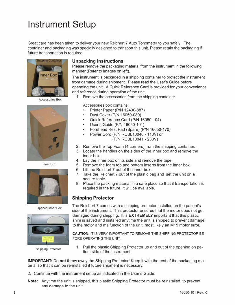
Unpacking InstructionsPlease remove the packaging material from the instrument in the following manner (Refer to images on left).The instrument is packaged in a shipping container to protect the instrument from damage during shipment. Please read the User’s Guide before operating the unit. A Quick Reference Card is provided for your convenience and reference during operation of the unit.
1. Remove the accessories from the shipping container.
Accessories box contains:• Printer Paper (P/N 12430-887)• Dust Cover (P/N 16050-089)• Quick Reference Card (P/N 16050-104)• User’s Guide (P/N 16050-101)• Forehead Rest Pad (Spare) (P/N 16050-170)• Power Cord (P/N RCBL10040 - 110V) or
(P/N RCBL10041 - 230V)
2. Remove the Top Foam (4 corners) from the shipping container.3. Locate the handles on the sides of the inner box and remove the
inner box.4. Lay the inner box on its side and remove the tape.5. Remove the foam top and bottom inserts from the inner box. 6. Lift the Reichert 7 out of the inner box.7. Take the Reichert 7 out of the plastic bag and set the unit on a
secure table.8. Place the packing material in a safe place so that if transportation is
required in the future, it will be available.
Shipping ProtectorThe Reichert 7 comes with a shipping protector installed on the patient’s side of the instrument. This protector ensures that the motor does not get damaged during shipping. It is EXTREMELY important that this plastic shim is saved and installed anytime the unit is shipped to prevent damage to the motor and malfunction of the unit, most likely an M15 motor error.
CAUTION: IT IS VERY IMPORTANT TO REMOVE THE SHIPPING PROTECTOR BE-FORE OPERATING THE UNIT.
1. Pull the plastic Shipping Protector up and out of the opening on pa-tient side of the instrument.
IMPORTANT: Do not throw away the Shipping Protector! Keep it with the rest of the packaging ma-terial so that it can be re-installed if future shipment is necessary.
2. Continue with the instrument setup as indicated in the User’s Guide.
Note: Anytime the unit is shipped, this plastic Shipping Protector must be reinstalled, to prevent any damage to the unit.
Inner Box
Opened Inner Box
Shipping Container
Inner Box
Accessories Box
Shipping Protector
16050-101 Rev. K 9
Instrument Setup (continued)
Application of Input PowerWARNING: CARE MUST BE TAKEN TO ARRANGE THE CABLES FOR THE ACCESSORIES SUCH THAT THEY DO NOT PRESENT A TRIPPING HAZARD TO THE EXAMINER OR A DANGER TO THE PATIENT.
WARNING: POSITION THIS INSTRUMENT SO THAT IT IS NOT DIFFICULT TO OPERATE THE DISCONNECTION DEVICE (PLUG).
1. After the unit is in its secure location, apply the correct input voltage to the instrument using the Power Cord from the Accessory Tray.
2. Press down on the “|” located on the ON/OFF Switch. The power inlet is located on the underside of the unit (Refer to page 10, item 8, for its location).
3. Read the User’s Guide and the Quick Reference Card before operating this instrument.
WARNING: DO NOT REMOVE THE OUTSIDE COVERS OF THE UNIT OR ATTEMPT TO REPAIR ANY INTERNAL PARTS. REPAIR AND SERVICE OF THE UNIT MUST BE PERFORMED BY EXPERIENCED PERSONNEL OR DEALERS THAT ARE TRAINED BY REICHERT.
CAUTION: ENSURE THAT THE VOLTAGE APPLIED TO THE UNIT IS THE SAME AS THE VOLTAGE THAT IS INDICATED ON THE DATA PLATE NEXT TO THE INPUT CORD RECEPTACLE OR DAMAGE TO THE UNIT MAY OCCUR.
CAUTION: FOR CONTINUED PROTECTION AGAINST THE RISK OF FIRE, ANY REPLACEMENT OF DAMAGED FUSES MUST BE IN ACCORDANCE WITH THE RATING AS INDICATED IN THE SPECIFICATIONS SECTION OF THIS MANUAL.
Disconnection of Input Power
1. At any time, the power switch can be set to OFF. The unit does not have a power down sequence. To terminate operation of this instrument, press the ON / OFF switch to the OFF position (O).
2. If this instrument is intended to be OFF for an extended period of time, it can be disconnected from power by detaching the power cord from the its receptacle.
16050-101 Rev. K10
Instrument Setup (continued)
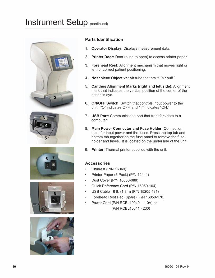
Parts Identification
1. Operator Display: Displays measurement data.
2. Printer Door: Door (push to open) to access printer paper.
3. Forehead Rest: Alignment mechanism that moves right or left for correct patient positioning.
4. Nosepiece Objective: Air tube that emits “air puff.”
5. Canthus Alignment Marks (right and left side): Alignment mark that indicates the vertical position of the center of the patient’s eye.
6. ON/OFF Switch: Switch that controls input power to the unit. “O” indicates OFF, and “ | ” indicates “ON.”
7. USB Port: Communication port that transfers data to a computer.
8. Main Power Connector and Fuse Holder: Connection point for input power and the fuses. Press the top tab and bottom tab together on the fuse panel to remove the fuse holder and fuses. It is located on the underside of the unit.
9. Printer: Thermal printer supplied with the unit.
Accessories• Chinrest (P/N 16049)• Printer Paper (5 Pack) (P/N 12441)• Dust Cover (P/N 16050-089)• Quick Reference Card (P/N 16050-104)• USB Cable - 6 ft. (1.8m) (P/N 15205-431)• Forehead Rest Pad (Spare) (P/N 16050-170)• Power Cord (P/N RCBL10040 - 110V) or
(P/N RCBL10041 - 230)
3
4
1
2
6 7
8
9
5

16050-101 Rev. K 11
Instrument Setup (continued)
Icon Definition
The Reichert 7 incorporates a user-friendly icon/menu-based operating system that will increase the speed of measurements, training and use. Listed below are the icons that are used during the operation of this instrument.
Icon Description
MENU — Accesses secondary level menus such as setup and help.
MEASURE — Initiates a single-puff measurement process.
TRIPLE MEASURE — Initiates a triple-puff measurement process.
QUADRUPLE MEASURE — Initiates a quadruple-puff measurement process.
DEMO — Allows patient to feel a soft demonstration air puff.
CLEAR DATA — Clears both right and left data on the Operator Display and in memory.
PRINT — Sends data to the printer.
SERVICE — Displays service information.
CANCEL — Cancels measurement process.
PROCEED — Proceeds with measurement process.
SELECT — Activates the new parameter or settings in the setup menus.
BACK — Returns to the preceding screen.
RIGHT ARROW — Moves right horizontally in the setup menus.
LEFT ARROW — Moves left horizontally in the setup menus.
DOWN ARROW — Moves down vertically in the setup menus.
16050-101 Rev. K12
Instrument Setup (continued)
Default Settings
The Reichert 7 has default settings that are set at the factory. To view a summary of these settings, refertopage13.Toviewadetaileddefinitionandexplanationofeachsetting,refertopages14through 17. Follow these steps to customize the default settings:1. Touch the screen on the MENU icon.2. Touch the UP/DOWN arrows icon to choose the appropriate setup category (e.g., Printout Setup).3. Touch the SELECT icon to display the parameters and settings of the setup categories.4. Touch the UP/DOWN arrows icon to move the cursor box to the desired parameter.5. Touch the SELECT icon to activate the highlighted parameter.6. Touch the appropriate RIGHT/LEFT arrows icon to move the cursor box to the desired setting for
the parameter.7. Touch the SELECT icon to activate the highlighted setting.8. Touch the BACK icon to step back through the previous menus until the Main Menu is shown.
CAUTION: DO NOT USE A POINTED OBJECT TO TOUCH THE SCREEN OR DAMAGE TO THE DISPLAY MAY RESULT.
16050-101 Rev. K 13
Instrument Setup (continued)
Default Settings (continued)
This instrument is sent from the factory with measurement, printer, communication, and miscellaneous parameters set to default settings. These settings can be changed to suit the needs of the individual operator or clinician. A summary of these settings is given below with the default selections shown in bold type. To customize these settings, follow the steps provided on page 12, Instrument Setup, Default Settings.
Customized Options
This instrument has the following default settings:
Tonometer Setup: (page 14)
Pressure: kPa, mmHgMeasurement: Avg[3], Avg[4]
Printout Setup: (page 15)
Date Format: MDY, DMY, YMDTime Format: AM/PM, 24 HRDate: 12/18/2007Time: 05:00PMPrinter: On, OffPractice: Reichert Communication Port Setup: (page 16)
Baud: 1200, 2400, 4800, 9600, 19200Parity: None, Even, OddData Bits: 7, 8Stop Bits: 1, 1.5, 2
General Setup: (page 17)
Language: Eng, Fra, Deu, Esp, Por, ItaTone: On, OffSleep: 5, 10, 20, 90 Contrast: - | | | | | | | | | +
Note: Default settings are shown in Bold type.
16050-101 Rev. K14
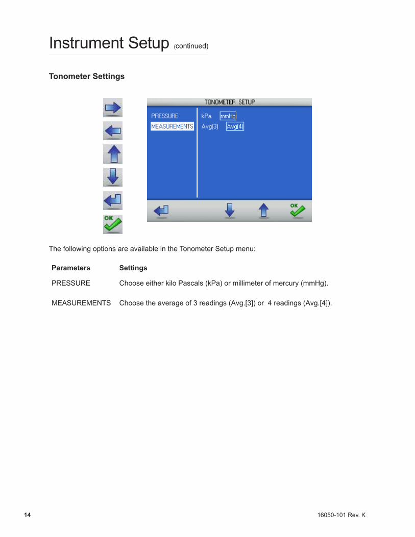
Tonometer Settings
The following options are available in the Tonometer Setup menu:
Parameters Settings
PRESSURE Choose either kilo Pascals (kPa) or millimeter of mercury (mmHg).
MEASUREMENTS Choose the average of 3 readings (Avg.[3]) or 4 readings (Avg.[4]).
Instrument Setup (continued)
16050-101 Rev. K 15
Instrument Setup (continued)
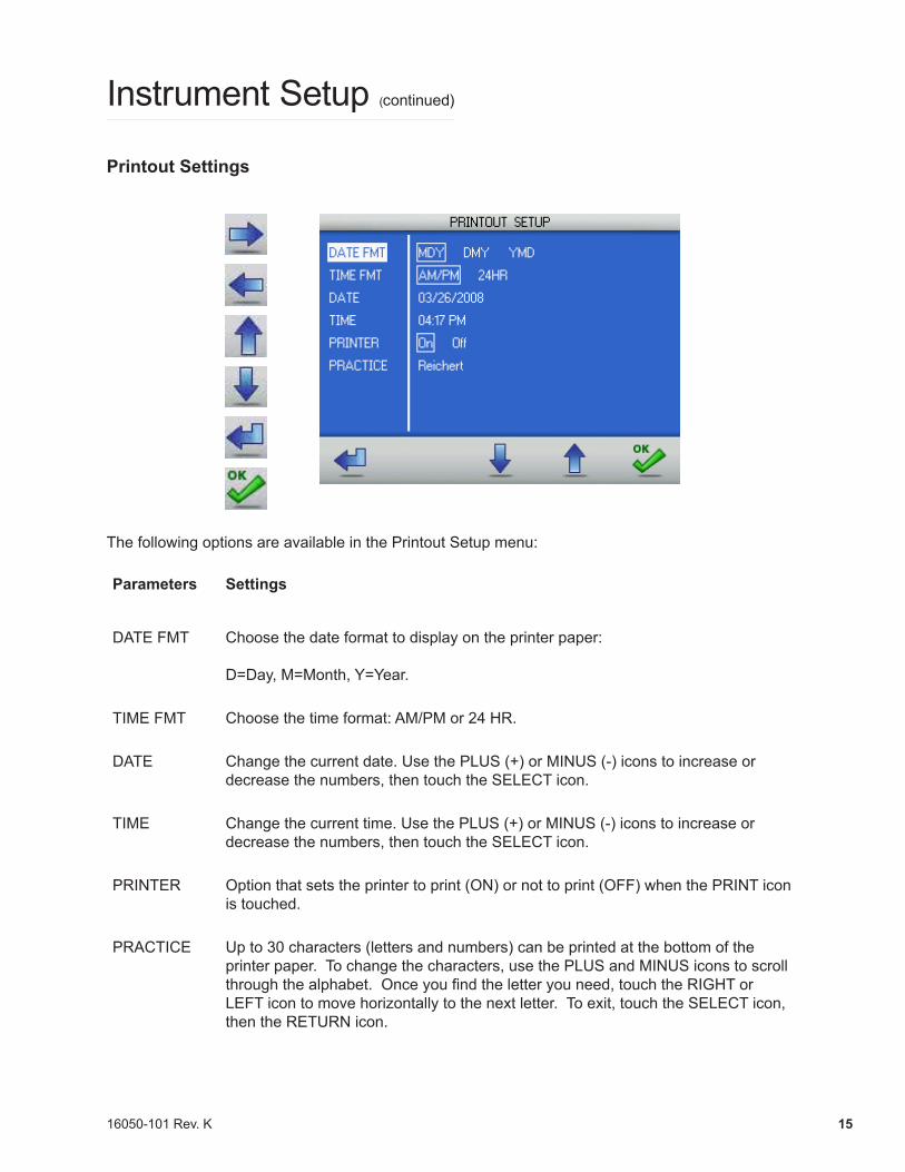
Printout Settings
The following options are available in the Printout Setup menu:
Parameters Settings
DATE FMT Choose the date format to display on the printer paper:
D=Day, M=Month, Y=Year.
TIME FMT Choose the time format: AM/PM or 24 HR.
DATE Change the current date. Use the PLUS (+) or MINUS (-) icons to increase or decrease the numbers, then touch the SELECT icon.
TIME Change the current time. Use the PLUS (+) or MINUS (-) icons to increase or decrease the numbers, then touch the SELECT icon.
PRINTER Option that sets the printer to print (ON) or not to print (OFF) when the PRINT icon is touched.
PRACTICE Up to 30 characters (letters and numbers) can be printed at the bottom of the printer paper. To change the characters, use the PLUS and MINUS icons to scroll through the alphabet. Once you find the letter you need, touch the RIGHT or LEFT icon to move horizontally to the next letter. To exit, touch the SELECT icon, then the RETURN icon.

16050-101 Rev. K16
Instrument Setup (continued)
Communications Settings
The Reichert 7 can transfer data to an external device, such as a computer, through the USB port.
The following options are available in the Communications Setup menu:
Parameters Settings
BAUD Serial transmission data rate, transfers in bits per second (bps).
PARITY Bits added to data transmission used to detect transmission errors. None, Even, or Odd are the available options.
DATA BITS Number of bits that make up data transmission word. Usually 7 or 8 bits in length.
STOP BITS Number of bits added to the end of the data transmission word to signal the end of transmission. Usually 1, 1.5, or 2 bits in length.
PRINTER Option that sets the printer to print (ON) or not to print (OFF) when the print button is pressed. When the printer is set to OFF, the patient data is sent only to the USB port. When the printer is set to ON, the patient data is sent to the printer and the USB port.
16050-101 Rev. K 17
Instrument Setup (continued)
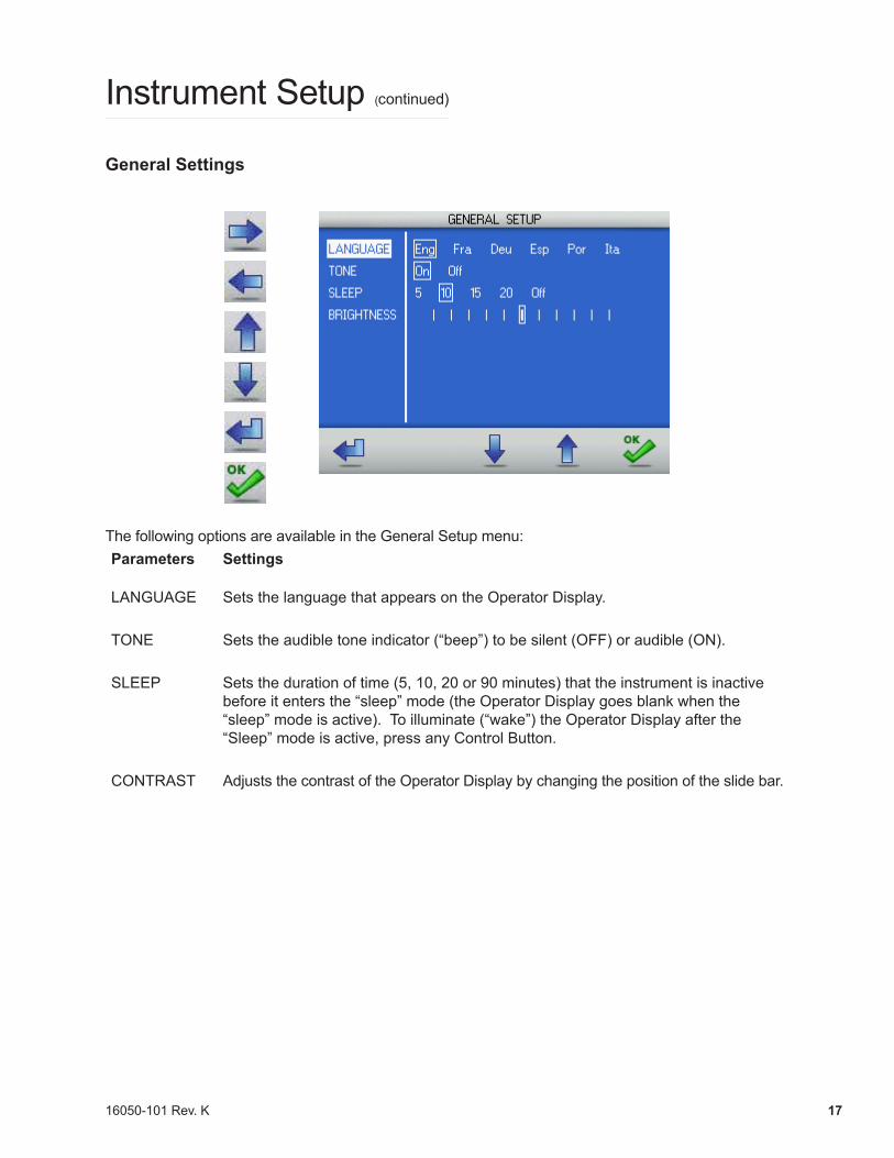
General Settings
The following options are available in the General Setup menu: Parameters Settings
LANGUAGE Sets the language that appears on the Operator Display.
TONE Sets the audible tone indicator (“beep”) to be silent (OFF) or audible (ON).
SLEEP Sets the duration of time (5, 10, 20 or 90 minutes) that the instrument is inactive before it enters the “sleep” mode (the Operator Display goes blank when the “sleep” mode is active). To illuminate (“wake”) the Operator Display after the “Sleep” mode is active, press any Control Button.
CONTRAST Adjusts the contrast of the Operator Display by changing the position of the slide bar.
16050-101 Rev. K18
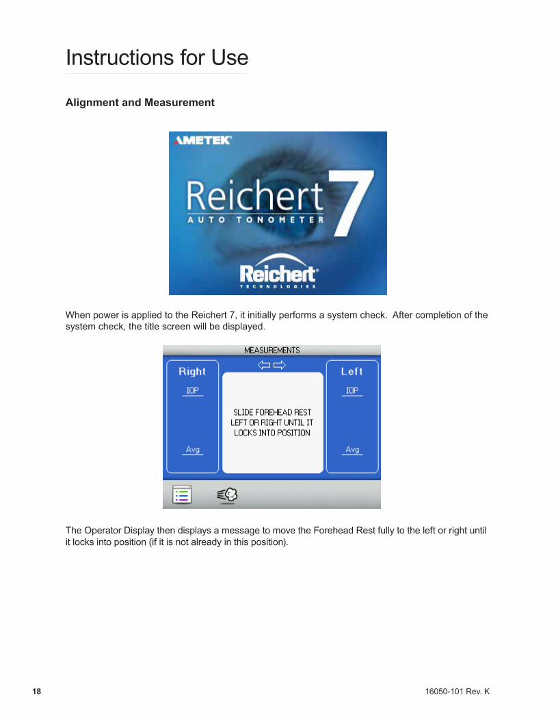
Alignment and Measurement
When power is applied to the Reichert 7, it initially performs a system check. After completion of the system check, the title screen will be displayed.
The Operator Display then displays a message to move the Forehead Rest fully to the left or right until it locks into position (if it is not already in this position).
Instructions for Use
16050-101 Rev. K 19
Instructions for Use (continued)
Alignment and Measurement (continued)
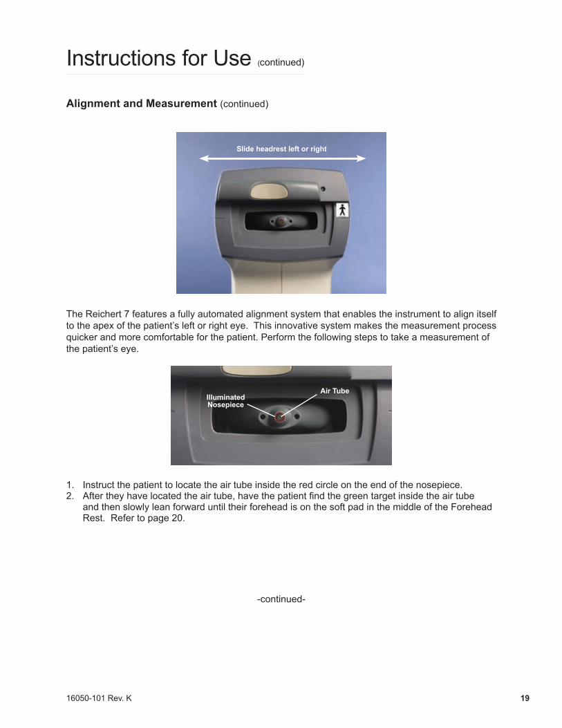
Slide headrest left or right
The Reichert 7 features a fully automated alignment system that enables the instrument to align itself to the apex of the patient’s left or right eye. This innovative system makes the measurement process quicker and more comfortable for the patient. Perform the following steps to take a measurement of the patient’s eye.
IlluminatedNosepiece
Air Tube
1. Instruct the patient to locate the air tube inside the red circle on the end of the nosepiece. 2. After they have located the air tube, have the patient find the green target inside the air tube
and then slowly lean forward until their forehead is on the soft pad in the middle of the Forehead Rest. Refer to page 20.
-continued-
16050-101 Rev. K20
Alignment and Measurement (continued)
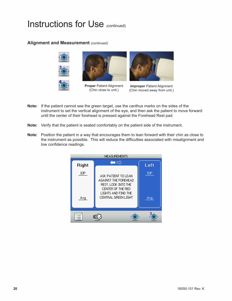
Proper Patient Alignment(Chin close to unit.)
Improper Patient Alignment(Chin moved away from unit.)
Note: If the patient cannot see the green target, use the canthus marks on the sides of the instrument to set the vertical alignment of the eye, and then ask the patient to move forward until the center of their forehead is pressed against the Forehead Rest pad.
Note: Verify that the patient is seated comfortably on the patient side of the instrument.
Note: Position the patient in a way that encourages them to lean forward with their chin as close to theinstrumentaspossible.Thiswillreducethedifficultiesassociatedwithmisalignmentandlowconfidencereadings.
Instructions for Use (continued)
16050-101 Rev. K 21
Alignment and Measurement (continued)
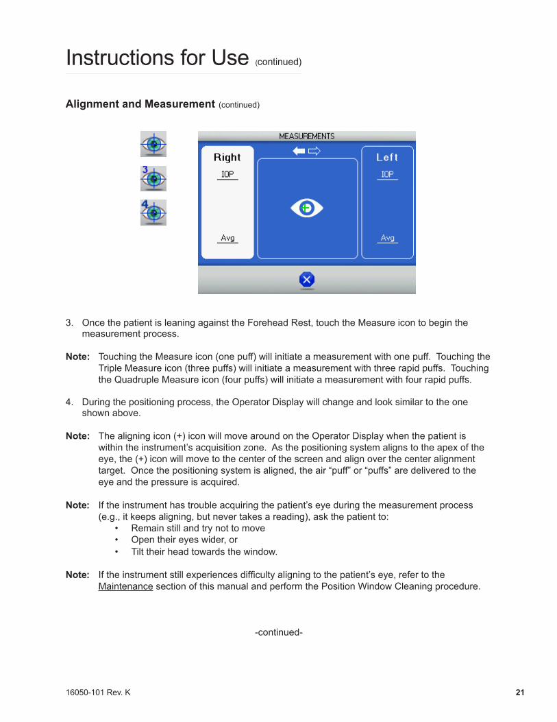
3. Once the patient is leaning against the Forehead Rest, touch the Measure icon to begin the measurement process.
Note: Touching the Measure icon (one puff) will initiate a measurement with one puff. Touching the Triple Measure icon (three puffs) will initiate a measurement with three rapid puffs. Touching the Quadruple Measure icon (four puffs) will initiate a measurement with four rapid puffs.
4. During the positioning process, the Operator Display will change and look similar to the one shown above.
Note: The aligning icon (+) icon will move around on the Operator Display when the patient is within the instrument’s acquisition zone. As the positioning system aligns to the apex of the eye, the (+) icon will move to the center of the screen and align over the center alignment target. Once the positioning system is aligned, the air “puff” or “puffs” are delivered to the eye and the pressure is acquired.
Note: If the instrument has trouble acquiring the patient’s eye during the measurement process (e.g., it keeps aligning, but never takes a reading), ask the patient to:
• Remain still and try not to move• Open their eyes wider, or• Tilt their head towards the window.
Note: Iftheinstrumentstillexperiencesdifficultyaligningtothepatient’seye,refertotheMaintenance section of this manual and perform the Position Window Cleaning procedure.
-continued-
Instructions for Use (continued)
16050-101 Rev. K22
Alignment and Measurement (continued)
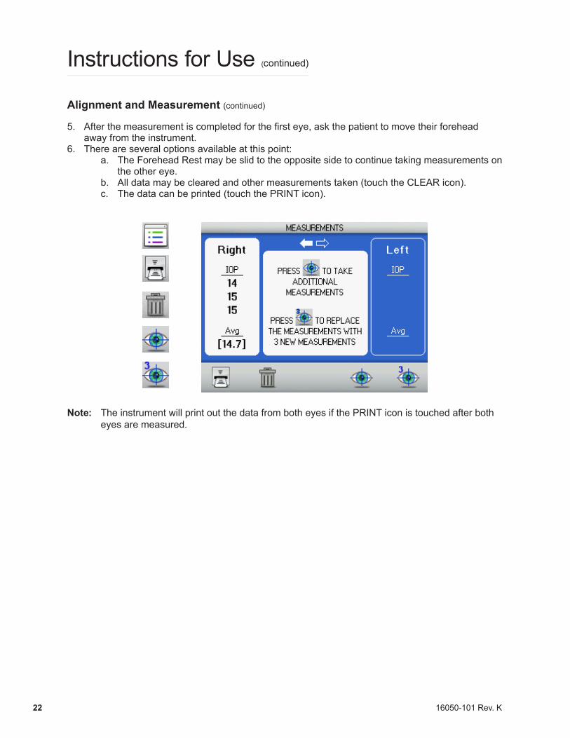
5. After the measurement is completed for the first eye, ask the patient to move their forehead away from the instrument.
6. There are several options available at this point:a. The Forehead Rest may be slid to the opposite side to continue taking measurements on
the other eye.b. All data may be cleared and other measurements taken (touch the CLEAR icon).c. The data can be printed (touch the PRINT icon).
Note: The instrument will print out the data from both eyes if the PRINT icon is touched after both eyes are measured.
Instructions for Use (continued)
16050-101 Rev. K 23
Instructions for Use (continued)
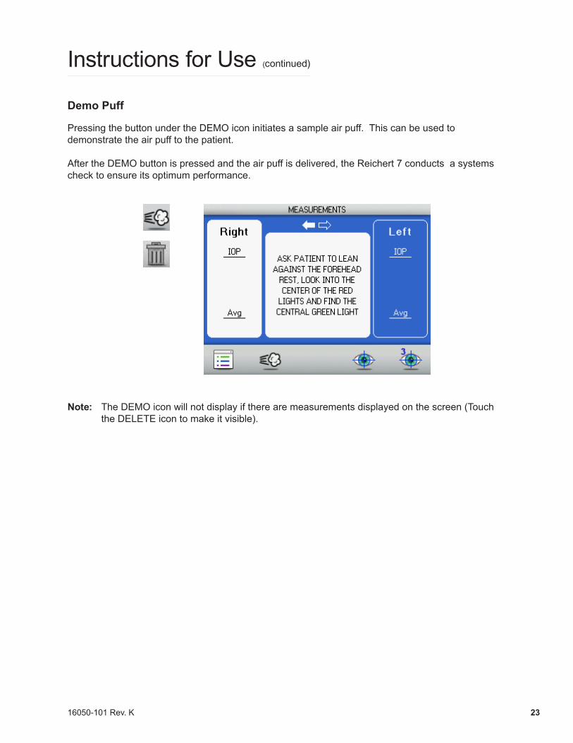
Demo Puff
Pressing the button under the DEMO icon initiates a sample air puff. This can be used to demonstrate the air puff to the patient.
After the DEMO button is pressed and the air puff is delivered, the Reichert 7 conducts a systems check to ensure its optimum performance.
Note: The DEMO icon will not display if there are measurements displayed on the screen (Touch the DELETE icon to make it visible).
16050-101 Rev. K24
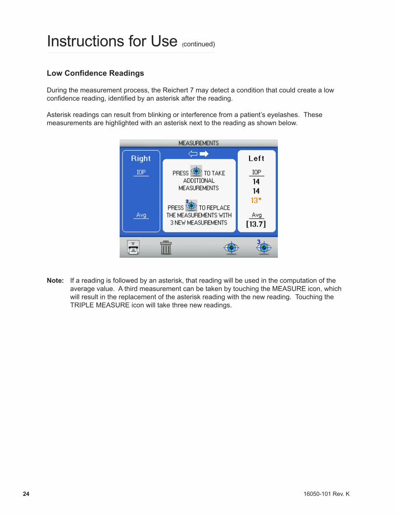
Low Confidence Readings
During the measurement process, the Reichert 7 may detect a condition that could create a low confidence reading, identified by an asterisk after the reading.
Asterisk readings can result from blinking or interference from a patient’s eyelashes. These measurements are highlighted with an asterisk next to the reading as shown below.
Note: If a reading is followed by an asterisk, that reading will be used in the computation of the average value. A third measurement can be taken by touching the MEASURE icon, which will result in the replacement of the asterisk reading with the new reading. Touching the TRIPLE MEASURE icon will take three new readings.
Instructions for Use (continued)
16050-101 Rev. K 25
Low Confidence Readings (continued)
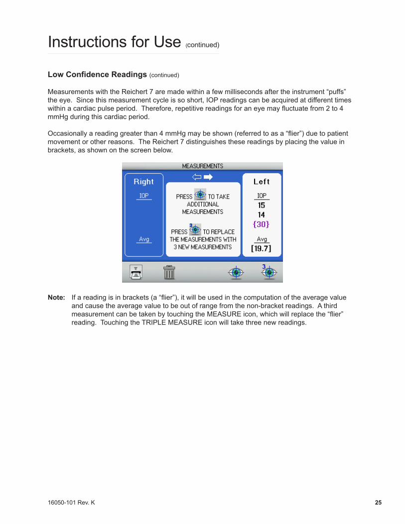
Measurements with the Reichert 7 are made within a few milliseconds after the instrument “puffs” the eye. Since this measurement cycle is so short, IOP readings can be acquired at different times within a cardiac pulse period. Therefore, repetitive readings for an eye may fluctuate from 2 to 4 mmHg during this cardiac period.
Occasionally a reading greater than 4 mmHg may be shown (referred to as a “flier”) due to patient movement or other reasons. The Reichert 7 distinguishes these readings by placing the value in brackets, as shown on the screen below.
Note: Ifareadingisinbrackets(a“flier”),itwillbeusedinthecomputationoftheaveragevalueand cause the average value to be out of range from the non-bracket readings. A third measurement can be taken by touching the MEASUREicon,whichwillreplacethe“flier”reading. Touching the TRIPLE MEASURE icon will take three new readings.
Instructions for Use (continued)
16050-101 Rev. K26
Instructions for Use (continued)
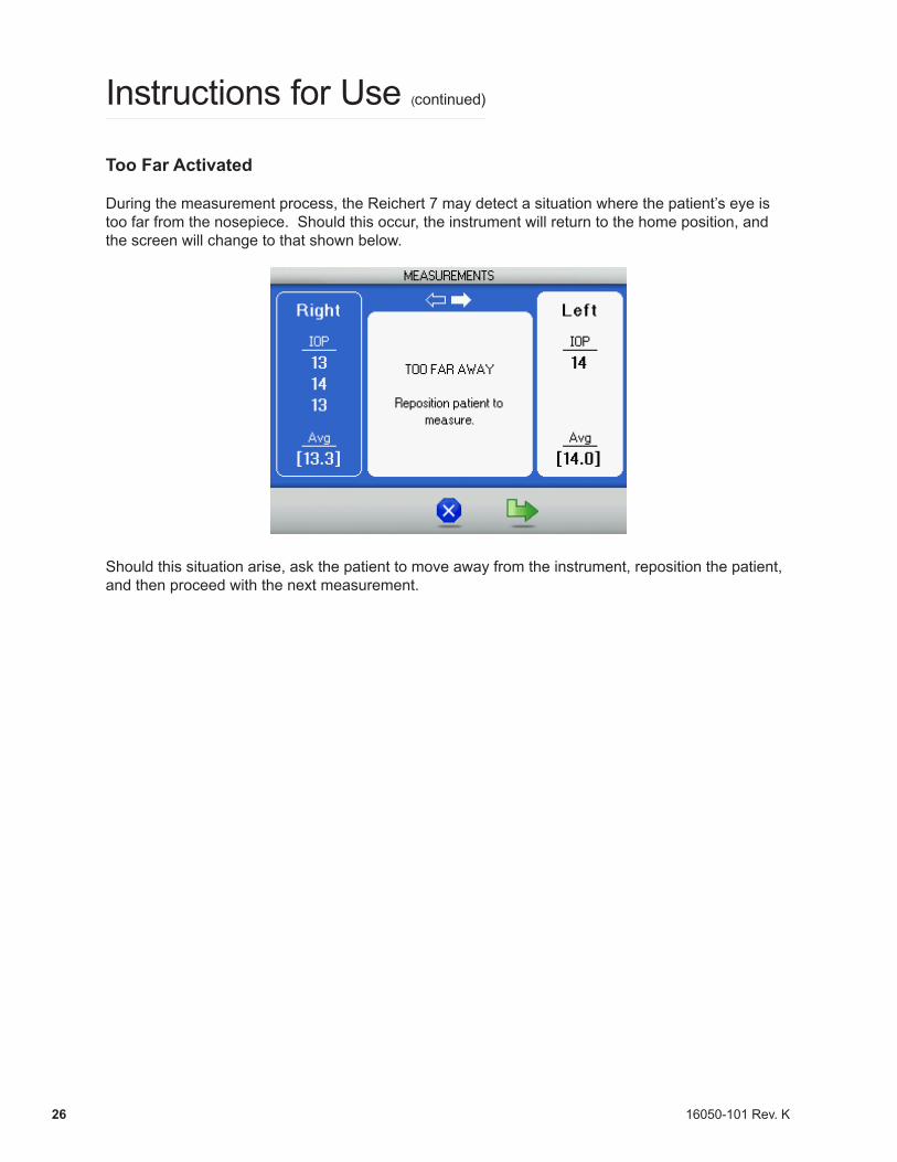
Too Far Activated
During the measurement process, the Reichert 7 may detect a situation where the patient’s eye is too far from the nosepiece. Should this occur, the instrument will return to the home position, and the screen will change to that shown below.
Should this situation arise, ask the patient to move away from the instrument, reposition the patient, and then proceed with the next measurement.
16050-101 Rev. K 27
Instructions for Use (continued)
Printing Measurement Data
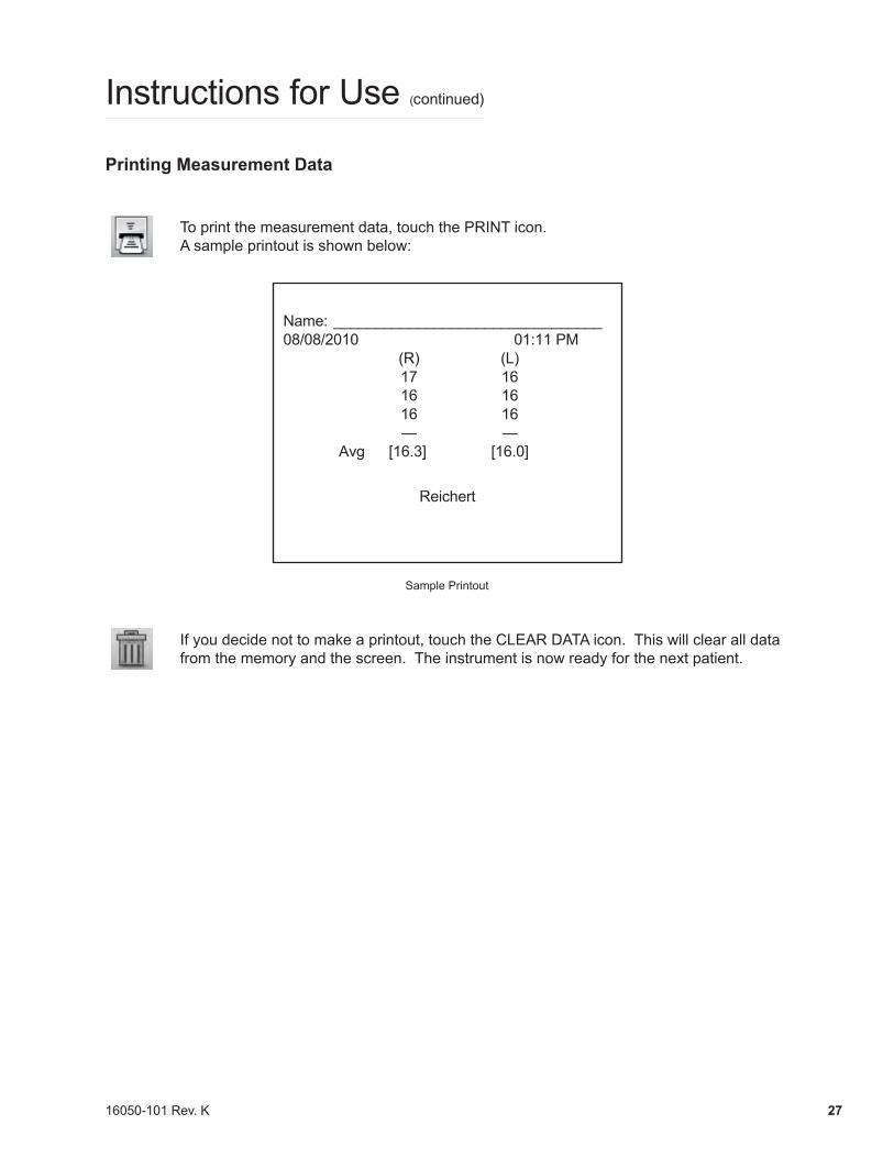
To print the measurement data, touch the PRINT icon. A sample printout is shown below:
Name: ________________________________08/08/2010 01:11 PM (R) (L) 17 16 16 16 16 16 — — Avg [16.3] [16.0]
Reichert
Sample Printout
If you decide not to make a printout, touch the CLEAR DATA icon. This will clear all data from the memory and the screen. The instrument is now ready for the next patient.
16050-101 Rev. K28
Cleaning & Maintenance
Fuses
WARNING: DISCONNECT POWER BEFORE ATTEMPTING TO REMOVE THE FUSES OR SERIOUS INJURY OR DEATH MAY OCCUR.
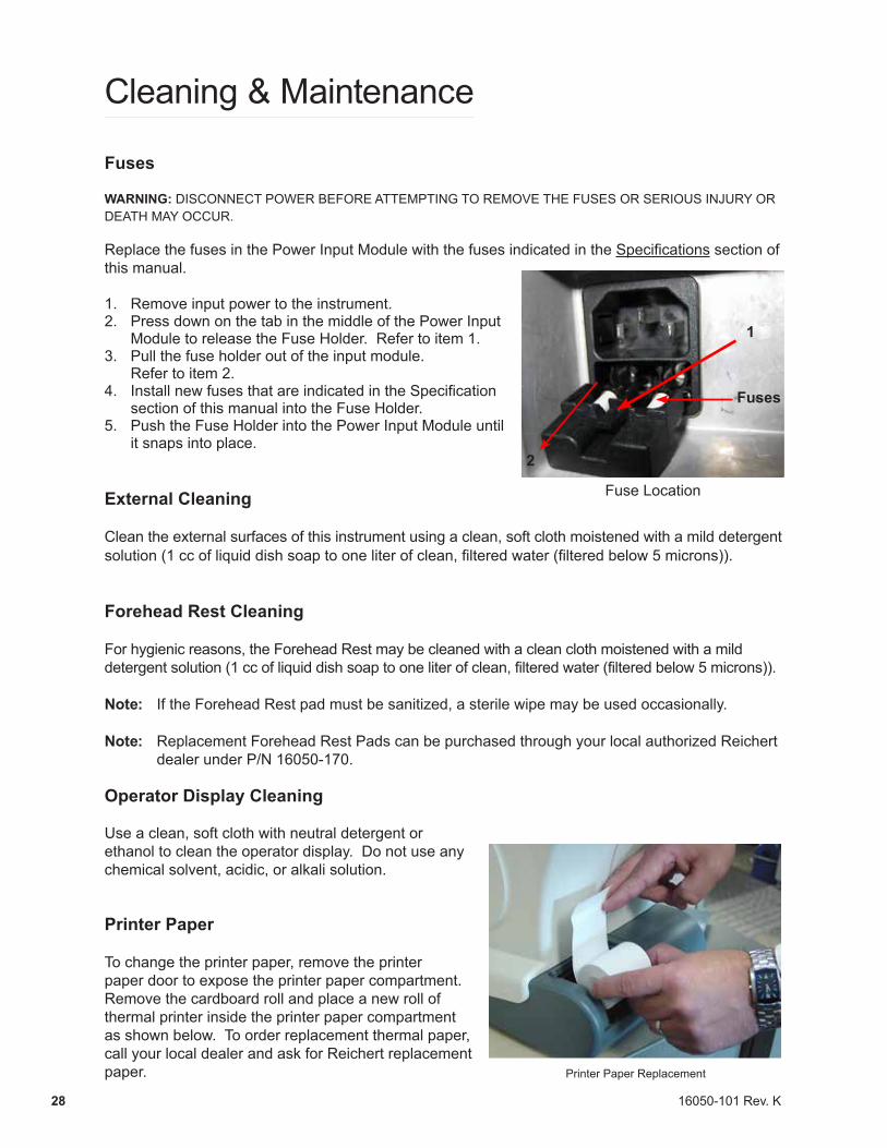
Replace the fuses in the Power Input Module with the fuses indicated in the Specifications section of this manual.
1. Remove input power to the instrument.2. Press down on the tab in the middle of the Power Input
Module to release the Fuse Holder. Refer to item 1.3. Pull the fuse holder out of the input module.
Refer to item 2.4. Install new fuses that are indicated in the Specification
section of this manual into the Fuse Holder.5. Push the Fuse Holder into the Power Input Module until
it snaps into place.
External Cleaning
Clean the external surfaces of this instrument using a clean, soft cloth moistened with a mild detergent solution (1 cc of liquid dish soap to one liter of clean, filtered water (filtered below 5 microns)).
Forehead Rest Cleaning
For hygienic reasons, the Forehead Rest may be cleaned with a clean cloth moistened with a mild detergent solution (1 cc of liquid dish soap to one liter of clean, filtered water (filtered below 5 microns)).
Note: If the Forehead Rest pad must be sanitized, a sterile wipe may be used occasionally.
Note: Replacement Forehead Rest Pads can be purchased through your local authorized Reichert dealer under P/N 16050-170.
Operator Display Cleaning
Use a clean, soft cloth with neutral detergent or ethanol to clean the operator display. Do not use any chemical solvent, acidic, or alkali solution.
Printer Paper
To change the printer paper, remove the printer paper door to expose the printer paper compartment. Remove the cardboard roll and place a new roll of thermal printer inside the printer paper compartment as shown below. To order replacement thermal paper, call your local dealer and ask for Reichert replacement paper.
Fuse Location
1
2
Fuses
Printer Paper Replacement
16050-101 Rev. K 29
Cleaning & Maintenance (continued)
Positioning Windows and Airtube Cleaning
When the Positioning Windows or the Applanation Windows become occluded with contaminants, degradation of the positioning signal occurs. When signal degradation occurs, the system may not recognize or position at the center of the eye. Consequently, the instrument will not find the center of the eye or align off center, which may prevent the unit from taking a measurement or can cause asterisk readings.
CAUTION: DO NOT USE ALCOHOL, SOLVENTS OR STRONG CLEANING SOLUTIONS ON THE ALIGNMENT WINDOWS OR DAMAGE TO THE WINDOWS WILL OCCUR.
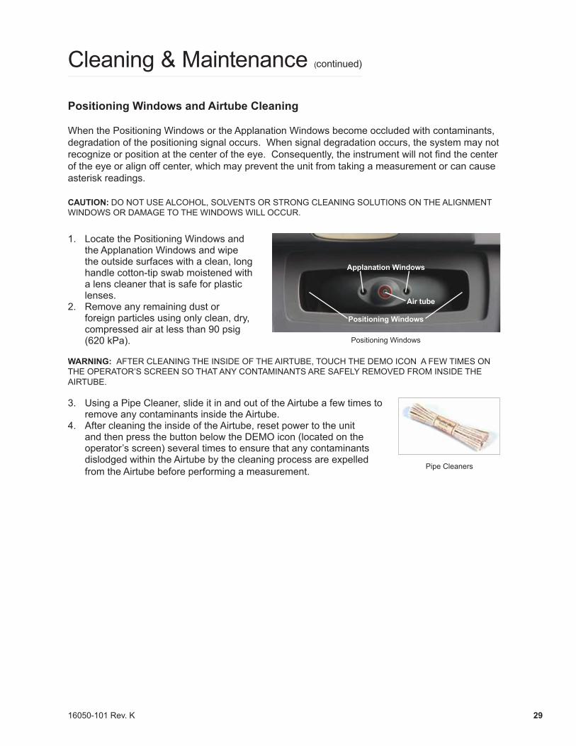
1. Locate the Positioning Windows and the Applanation Windows and wipe the outside surfaces with a clean, long handle cotton-tip swab moistened with a lens cleaner that is safe for plastic lenses.
2. Remove any remaining dust or foreign particles using only clean, dry, compressed air at less than 90 psig (620 kPa).
WARNING: AFTER CLEANING THE INSIDE OF THE AIRTUBE, TOUCH THE DEMO ICON A FEW TIMES ON THE OPERATOR’S SCREEN SO THAT ANY CONTAMINANTS ARE SAFELY REMOVED FROM INSIDE THE AIRTUBE.
3. Using a Pipe Cleaner, slide it in and out of the Airtube a few times to remove any contaminants inside the Airtube.
4. After cleaning the inside of the Airtube, reset power to the unit and then press the button below the DEMO icon (located on the operator’s screen) several times to ensure that any contaminants dislodged within the Airtube by the cleaning process are expelled from the Airtube before performing a measurement.
Applanation Windows
Air tube
Positioning Windows
Positioning Windows
Pipe Cleaners
16050-101 Rev. K30
Forehead Rest Pad Replacement
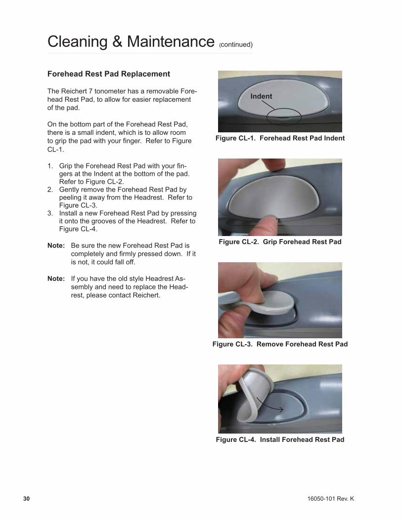
The Reichert 7 tonometer has a removable Fore-head Rest Pad, to allow for easier replacement of the pad.
On the bottom part of the Forehead Rest Pad, there is a small indent, which is to allow room to grip the pad with your finger. Refer to Figure CL-1.
1. Grip the Forehead Rest Pad with your fin-gers at the Indent at the bottom of the pad. Refer to Figure CL-2.
2. Gently remove the Forehead Rest Pad by peeling it away from the Headrest. Refer to Figure CL-3.
3. Install a new Forehead Rest Pad by pressing it onto the grooves of the Headrest. Refer to Figure CL-4.
Note: Be sure the new Forehead Rest Pad is completelyandfirmlypresseddown.Ifitis not, it could fall off.
Note: If you have the old style Headrest As-
sembly and need to replace the Head-rest, please contact Reichert.
Indent
Figure CL-1. Forehead Rest Pad Indent
Figure CL-2. Grip Forehead Rest Pad
Figure CL-3. Remove Forehead Rest Pad
Figure CL-4. Install Forehead Rest Pad
Cleaning & Maintenance (continued)
16050-101 Rev. K 31
Troubleshooting
Help Screens
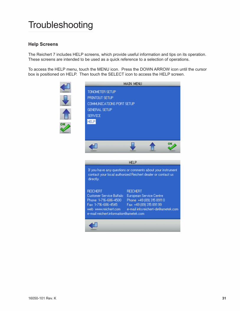
The Reichert 7 includes HELP screens, which provide useful information and tips on its operation. These screens are intended to be used as a quick reference to a selection of operations.
To access the HELP menu, touch the MENU icon. Press the DOWN ARROW icon until the cursor box is positioned on HELP. Then touch the SELECT icon to access the HELP screen.
16050-101 Rev. K32
Troubleshooting (continued)
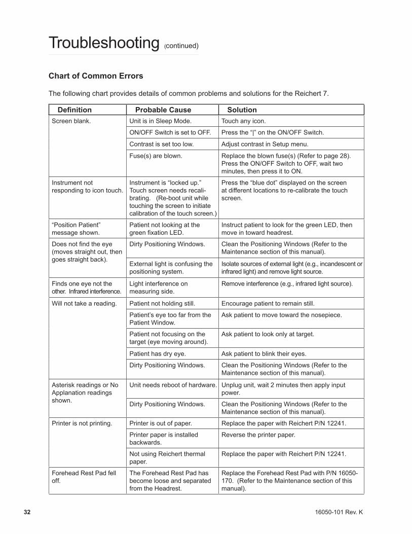
Chart of Common Errors
The following chart provides details of common problems and solutions for the Reichert 7.
Definition Probable Cause SolutionScreen blank. Unit is in Sleep Mode. Touch any icon.
ON/OFF Switch is set to OFF. Press the “|” on the ON/OFF Switch.
Contrast is set too low. Adjust contrast in Setup menu.
Fuse(s) are blown. Replace the blown fuse(s) (Refer to page 28).Press the ON/OFF Switch to OFF, wait two minutes, then press it to ON.
Instrument not responding to icon touch.
Instrument is “locked up.” Touch screen needs recali-brating. (Re-boot unit while touching the screen to initiate calibration of the touch screen.)
Press the “blue dot” displayed on the screen at different locations to re-calibrate the touch screen.
“Position Patient” message shown.
Patient not looking at the green fixation LED.
Instruct patient to look for the green LED, then move in toward headrest.
Does not find the eye (moves straight out, then goes straight back).
Dirty Positioning Windows. Clean the Positioning Windows (Refer to the Maintenance section of this manual).
External light is confusing the positioning system.
Isolate sources of external light (e.g., incandescent or infrared light) and remove light source.
Finds one eye not the other. Infrared interference.
Light interference on measuring side.
Remove interference (e.g., infrared light source).
Will not take a reading. Patient not holding still. Encourage patient to remain still.
Patient’s eye too far from the Patient Window.
Ask patient to move toward the nosepiece.
Patient not focusing on the target (eye moving around).
Ask patient to look only at target.
Patient has dry eye. Ask patient to blink their eyes.
Dirty Positioning Windows. Clean the Positioning Windows (Refer to the Maintenance section of this manual).
Asterisk readings or No Applanation readings shown.
Unit needs reboot of hardware. Unplug unit, wait 2 minutes then apply input power.
Dirty Positioning Windows. Clean the Positioning Windows (Refer to the Maintenance section of this manual).
Printer is not printing. Printer is out of paper. Replace the paper with Reichert P/N 12241.
Printer paper is installed backwards.
Reverse the printer paper.
Not using Reichert thermal paper.
Replace the paper with Reichert P/N 12241.
Forehead Rest Pad fell off.
The Forehead Rest Pad has become loose and separated from the Headrest.
Replace the Forehead Rest Pad with P/N 16050-170. (Refer to the Maintenance section of this manual).
16050-101 Rev. K 33
Troubleshooting (continued)
Print-Related Errors
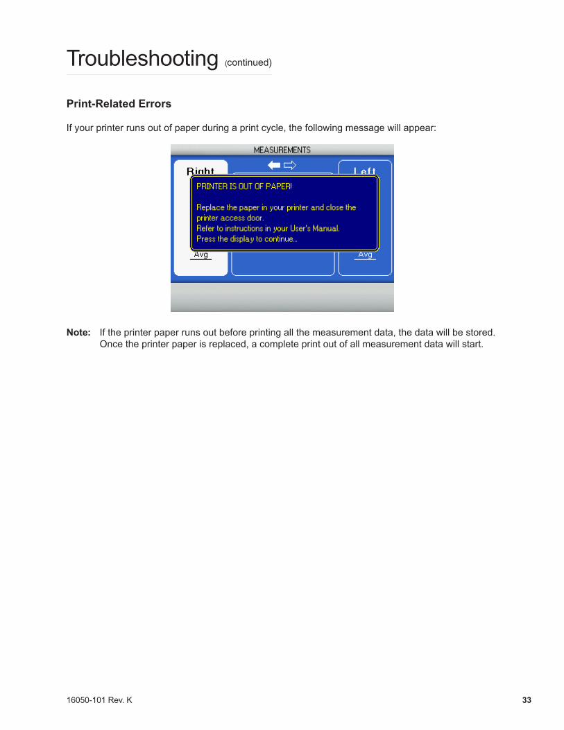
If your printer runs out of paper during a print cycle, the following message will appear:
Note: If the printer paper runs out before printing all the measurement data, the data will be stored. Once the printer paper is replaced, a complete print out of all measurement data will start.
16050-101 Rev. K34
Specifications
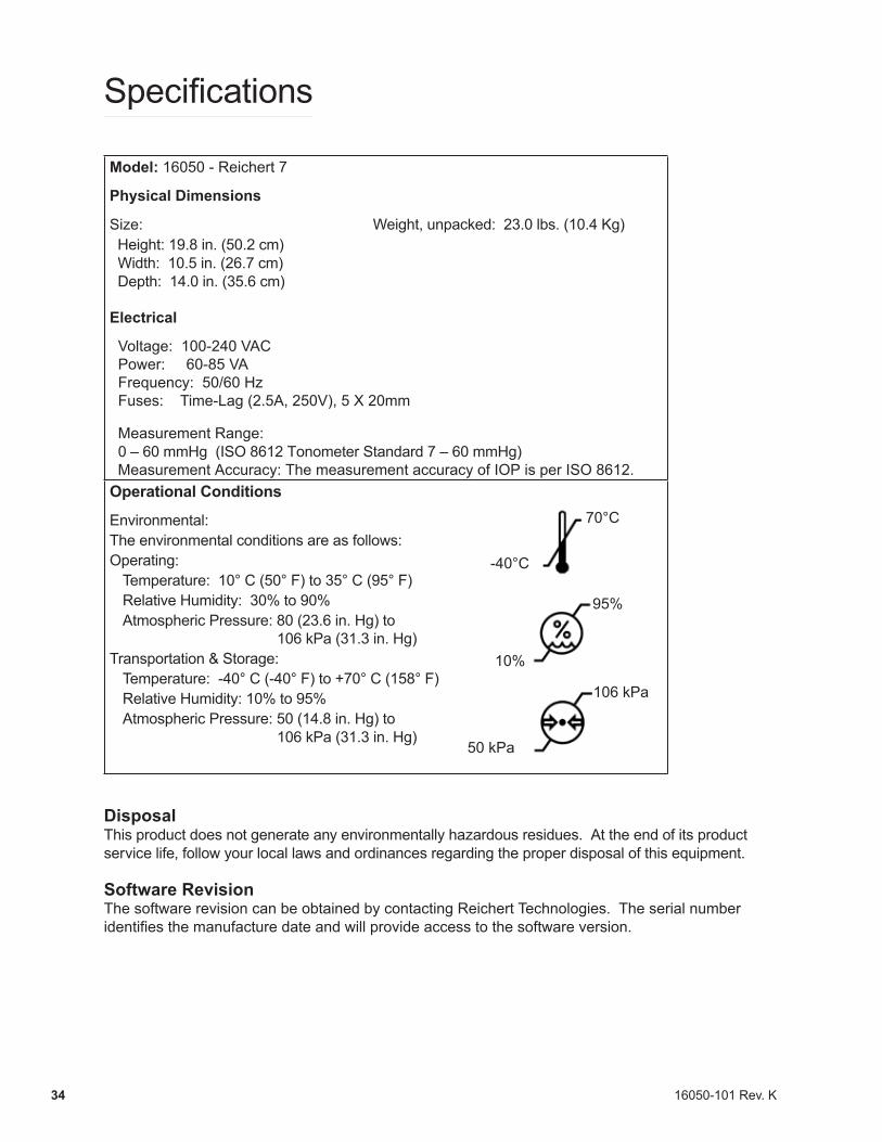
Model: 16050 - Reichert 7
Physical Dimensions
Size: Weight, unpacked: 23.0 lbs. (10.4 Kg) Height: 19.8 in. (50.2 cm) Width: 10.5 in. (26.7 cm) Depth: 14.0 in. (35.6 cm)
Electrical
Voltage: 100-240 VAC Power: 60-85 VA Frequency: 50/60 Hz Fuses: Time-Lag (2.5A, 250V), 5 X 20mm
Measurement Range: 0 – 60 mmHg (ISO 8612 Tonometer Standard 7 – 60 mmHg) Measurement Accuracy: The measurement accuracy of IOP is per ISO 8612.Operational Conditions
Environmental:The environmental conditions are as follows:Operating:
Temperature: 10° C (50° F) to 35° C (95° F) Relative Humidity: 30% to 90%Atmospheric Pressure: 80 (23.6 in. Hg) to 106 kPa (31.3 in. Hg)
Transportation & Storage:Temperature: -40° C (-40° F) to +70° C (158° F)Relative Humidity: 10% to 95%Atmospheric Pressure: 50 (14.8 in. Hg) to 106 kPa (31.3 in. Hg)
DisposalThis product does not generate any environmentally hazardous residues. At the end of its product service life, follow your local laws and ordinances regarding the proper disposal of this equipment.
Software RevisionThe software revision can be obtained by contacting Reichert Technologies. The serial number identifies the manufacture date and will provide access to the software version.
-40°C
70°C
10%
95%
106 kPa
50 kPa
16050-101 Rev. K 35
Classifications
The Reichert 7 is classified as Class I Equipment.
Class I Equipment is equipment in which protection against electric shock does not rely on basic insulation only, but which includes an additional safety precaution in that means are provided for the connection of the equipment to a protective earth conductor in the fixed wiring of the installation in such a way which accessible metal parts cannot become live in the event of a failure of the basic insulation.
The Reichert 7 is classified as Type B Equipment.
Type B Equipment provides an adequate degree of protection against electrical shock, particularly regarding allowable leakage currents and reliability of the protective earth connection.
The Reichert 7 is classified as IPX0 Equipment.
IPX0 Equipment is ordinary equipment enclosed without protection against ingress of water.
According to the mode of operation, the Reichert 7 is a Continuous Operation instrument.
16050-101 Rev. K36
Guidance Tables
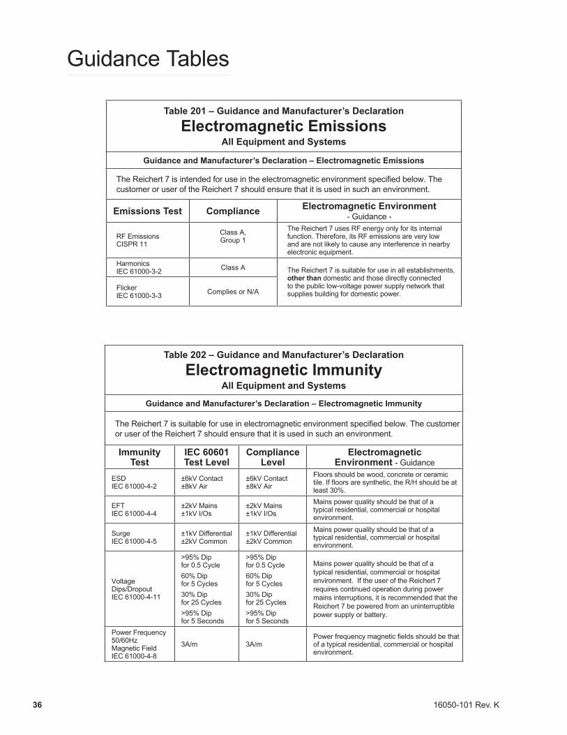
Table 201 – Guidance and Manufacturer’s Declaration
Electromagnetic EmissionsAll Equipment and Systems
Guidance and Manufacturer’s Declaration – Electromagnetic Emissions
TheReichert7isintendedforuseintheelectromagneticenvironmentspecifiedbelow.Thecustomer or user of the Reichert 7 should ensure that it is used in such an environment.
Emissions Test Compliance Electromagnetic Environment - Guidance -
RF Emissions CISPR 11
Class A, Group 1
The Reichert 7 uses RF energy only for its internal function. Therefore, its RF emissions are very low and are not likely to cause any interference in nearby electronic equipment.
Harmonics IEC 61000-3-2 Class A The Reichert 7 is suitable for use in all establishments,
other than domestic and those directly connected to the public low-voltage power supply network that supplies building for domestic power.
Flicker IEC 61000-3-3 Complies or N/A
Table 202 – Guidance and Manufacturer’s Declaration
Electromagnetic ImmunityAll Equipment and Systems
Guidance and Manufacturer’s Declaration – Electromagnetic Immunity
TheReichert7issuitableforuseinelectromagneticenvironmentspecifiedbelow.Thecustomeror user of the Reichert 7 should ensure that it is used in such an environment.
Immunity Test
IEC 60601 Test Level
Compliance Level
Electromagnetic Environment - Guidance
ESD IEC 61000-4-2
±6kV Contact ±8kV Air
±6kV Contact ±8kV Air
Floors should be wood, concrete or ceramic tile.Iffloorsaresynthetic,theR/Hshouldbeatleast 30%.
EFT IEC 61000-4-4
±2kV Mains ±1kV I/Os
±2kV Mains ±1kV I/Os
Mains power quality should be that of a typical residential, commercial or hospital environment.
Surge IEC 61000-4-5
±1kV Differential ±2kV Common
±1kV Differential ±2kV Common
Mains power quality should be that of a typical residential, commercial or hospital environment.
Voltage Dips/Dropout IEC 61000-4-11
>95% Dip for 0.5 Cycle60% Dip for 5 Cycles30% Dip for 25 Cycles>95% Dip for 5 Seconds
>95% Dip for 0.5 Cycle60% Dip for 5 Cycles30% Dip for 25 Cycles>95% Dip for 5 Seconds
Mains power quality should be that of a typical residential, commercial or hospital environment. If the user of the Reichert 7 requires continued operation during power mains interruptions, it is recommended that the Reichert 7 be powered from an uninterruptible power supply or battery.
Power Frequency 50/60Hz Magnetic Field IEC 61000-4-8
3A/m 3A/mPowerfrequencymagneticfieldsshouldbethatof a typical residential, commercial or hospital environment.
16050-101 Rev. K 37
Guidance Tables (continued)
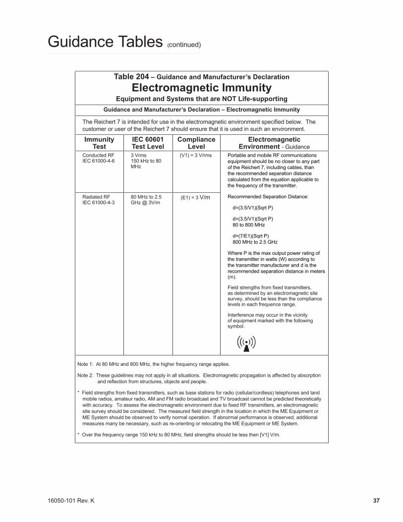
Table 204 – Guidance and Manufacturer’s Declaration
Electromagnetic ImmunityEquipment and Systems that are NOT Life-supporting
Guidance and Manufacturer’s Declaration – Electromagnetic Immunity
TheReichert7isintendedforuseintheelectromagneticenvironmentspecifiedbelow.Thecustomer or user of the Reichert 7 should ensure that it is used in such an environment.
Immunity Test
IEC 60601 Test Level
Compliance Level
Electromagnetic Environment - Guidance
Conducted RF IEC 61000-4-6
3 Vrms 150 kHz to 80 MHz
(V1) = 3 V/rms Portable and mobile RF communications equipment should be no closer to any part of the Reichert 7, including cables, than the recommended separation distance calculated from the equation applicable to the frequency of the transmitter.
Recommended Separation Distance:
d=(3.5/V1)(Sqrt P)
d=(3.5/V1)(Sqrt P) 80 to 800 MHz
d=(7/E1)(Sqrt P) 800 MHz to 2.5 GHz
Where P is the max output power rating of the transmitter in watts (W) according to the transmitter manufacturer and d is the recommended separation distance in meters (m).
Fieldstrengthsfromfixedtransmitters,as determined by an electromagnetic site survey, should be less than the compliance levels in each frequence range.
Interference may occur in the vicinity of equipment marked with the following symbol.
Radiated RF IEC 61000-4-3
80 MHz to 2.5 GHz @ 3V/m
(E1) = 3 V/m
Note 1: At 80 MHz and 800 MHz, the higher frequency range applies.
Note 2: These guidelines may not apply in all situations. Electromagnetic propagation is affected by absorption andreflectionfromstructures,objectsandpeople.
*Fieldstrengthsfromfixedtransmitters,suchasbasestationsforradio(cellular/cordless)telephonesandlandmobile radios, amateur radio, AM and FM radio broadcast and TV broadcast cannot be predicted theoretically withaccuracy.ToassesstheelectromagneticenvironmentduetofixedRFtransmitters,anelectromagneticsitesurveyshouldbeconsidered.ThemeasuredfieldstrengthinthelocationinwhichtheMEEquipmentorME System should be observed to verify normal operation. If abnormal performance is observed, additional measures many be necessary, such as re-orienting or relocating the ME Equipment or ME System.
*Overthefrequencyrange150kHzto80MHz,fieldstrengthsshouldbelessthen[V1]V/m.
16050-101 Rev. K38
Guidance Tables (continued)
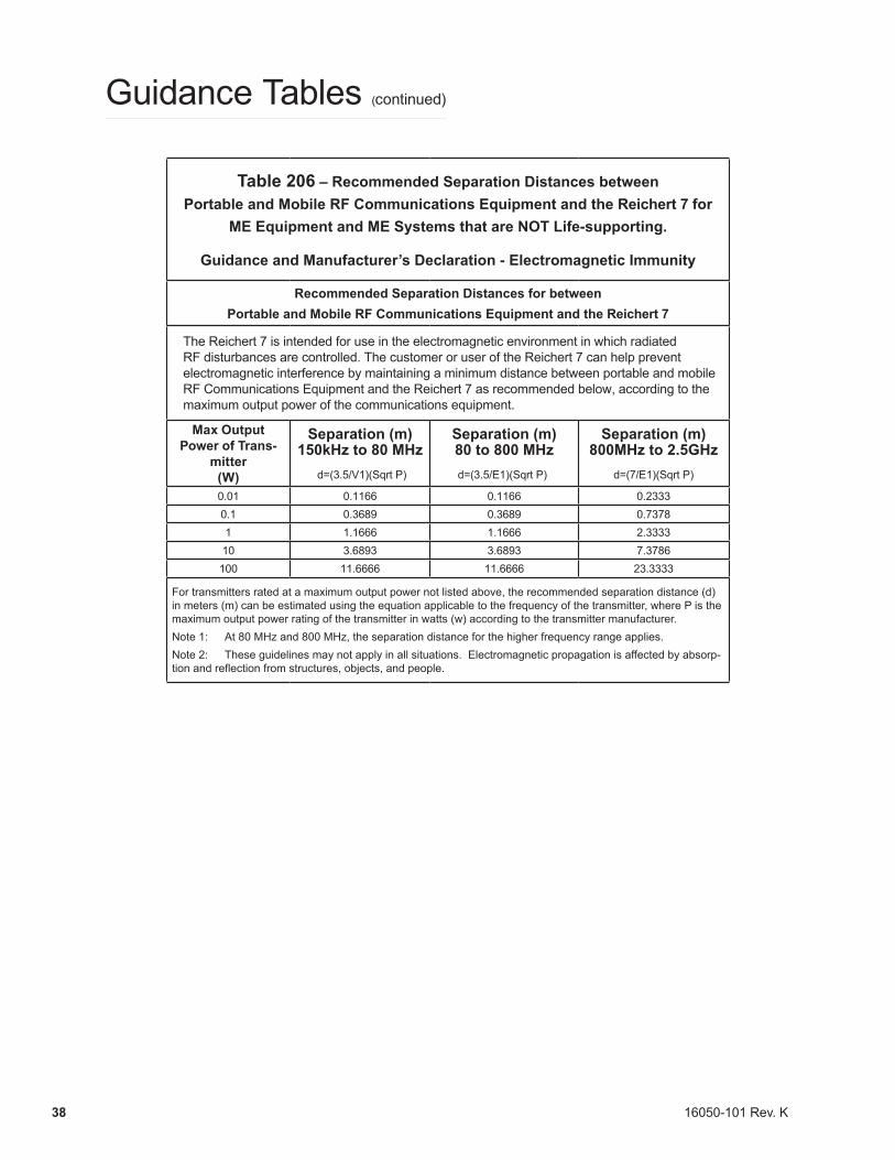
Table 206 – Recommended Separation Distances between Portable and Mobile RF Communications Equipment and the Reichert 7 for
ME Equipment and ME Systems that are NOT Life-supporting.
Guidance and Manufacturer’s Declaration - Electromagnetic Immunity
Recommended Separation Distances for between Portable and Mobile RF Communications Equipment and the Reichert 7
The Reichert 7 is intended for use in the electromagnetic environment in which radiated RF disturbances are controlled. The customer or user of the Reichert 7 can help prevent electromagnetic interference by maintaining a minimum distance between portable and mobile RF Communications Equipment and the Reichert 7 as recommended below, according to the maximum output power of the communications equipment.
Max Output Power of Trans-
mitter(W)
Separation (m)150kHz to 80 MHz
d=(3.5/V1)(Sqrt P)
Separation (m)80 to 800 MHzd=(3.5/E1)(Sqrt P)
Separation (m)800MHz to 2.5GHz
d=(7/E1)(Sqrt P)
0.01 0.1166 0.1166 0.23330.1 0.3689 0.3689 0.73781 1.1666 1.1666 2.333310 3.6893 3.6893 7.3786100 11.6666 11.6666 23.3333
For transmitters rated at a maximum output power not listed above, the recommended separation distance (d) in meters (m) can be estimated using the equation applicable to the frequency of the transmitter, where P is the maximum output power rating of the transmitter in watts (w) according to the transmitter manufacturer.Note 1: At 80 MHz and 800 MHz, the separation distance for the higher frequency range applies.Note 2: These guidelines may not apply in all situations. Electromagnetic propagation is affected by absorp-tionandreflectionfromstructures,objects,andpeople.
16050-101 Rev. K 39
Warranty
This product is warranted by Reichert Technologies (“Reichert”) against defective material and workmanship under normal use for a period of one year from the date of invoice to the original purchaser. (An authorized dealer shall not be considered an original purchaser.) Under this warranty, Reichert’s sole obligation is to repair or replace the defective part or product at Reichert’s discretion.
This warranty applies to new products and does not apply to a product that has been tampered with, alteredin any way, misused, damaged by accident or negligence, or that has the serial number removed, altered or effaced. Nor shall this warranty be extended to a product installed or operated in a manner not in accordance with the applicable Reichert instruction manual, nor to a product that has been sold, serviced, installed or repaired other than by a Reichert factory, Technical Service Center, or authorized Reichert Technologies Dealer.
Lamps, bulbs, charts, cards and other expendable items are not covered by this warranty.
All claims under this warranty must be in writing directed to the Reichert factory, Technical Service Center, or authorized instrument dealer making the original sale and must be accompanied by a copy of the purchaser’s invoice.
This warranty is in lieu of all other warranties implied or expressed. All implied warranties of merchantability or fitness for a particular use are hereby disclaimed. No representative or other person is authorized to make any other obligations for Reichert. Reichert shall not be liable for any special, incidental, or consequent damages for any negligence, breach of warranty, strict liability or any other damages resulting from or relating to design, manufacture, sale, use or handling of the product.
PATENT WARRANTYIf notified promptly in writing of any action brought against the purchaser based on a claim that the instrument infringes a U.S. Patent, Reichert will defend such action at its expense and will pay costs and damages awarded in any such action, provided that Reichert shall have sole control of the defense of any such action with information and assistance (at Reichert’s expense) for such defense, and of all negotiation for the settlement and compromise thereof.
PRODUCT CHANGESReichert reserves the right to make changes in design or to make additions to or improvements in its products without obligation to add such to products previously manufactured. CLAIMS FOR SHORTAGES We use extreme care in selection, checking, rechecking and packing to eliminate the possibility of error. If any shipping errors are discovered:1. Carefully go through the packing materials to be sure nothing was inadvertently overlooked when the
unit was unpacked. 2. Call the dealer you purchased the product from and report the shortage. The materials are packed at
the factory and none should be missing if the box has never been opened. 3. Claims should be filed within 30 days.
CLAIMS FOR DAMAGES IN TRANSITOur shipping responsibility ceases with the safe delivery in good condition to the transportation company. Claims for loss or damage in transit should be made promptly and directly to the transportation company.
If, upon delivery, the outside of the packing case shows evidence of rough handling or damage, the transportation company’s agent should be requested to make a “Received in Bad Order” notation on the delivery receipt. If within 48 hours of delivery, concealed damage is noted upon unpacking the shipment and no exterior evidence of rough handling is apparent, the transportation company should be requested to make out a “Bad Order” report. This procedure is necessary in order for the dealer to maintain the right of recovery from the carrier.

Manufactured ByReichert, Inc.
3362 Walden AveDepew, NY 14043
USA
Toll Free 888-849-8955Phone: 716-686-4500
Fax: 716-686-4555Email: [email protected]
www.reichert.com
Authorized European RepresentativeAMETEK GmbH
Business Unit ReichertCarl-von-Linde-Strasse 42
85716 Unterschleissheim/MunichGermany
Email: [email protected]
Tel: +49 (89) 315 8911 0Fax: +49 (89) 315 891 99
ISO-9001/13485 Certified
16050-101 Rev. K2016-05-04