auto-draft inducer installation instructions … · installation restrictions failure to install,...
TRANSCRIPT
Copyright © 2000, Tjernlund Products, Inc. All rights reserved. P/N 8504003
REV. A 7/00
AUTO-DRAFT® INDUCERINSTALLATION INSTRUCTIONS
MODELS
DJ-3 ILD-3 XLI HD
OWNER INSTRUCTIONS, DO NOT DESTROY
Recognize this symbol as an indication of important Safety Information!
NOTE: FLUE GAS TEMPERATURES MUST NOT EXCEED
575oF AT DRAFT INDUCER INLET. DRAFT INDUCERS MUST NOT BE USED FOR SIDEWALL VENTING APPLICATIONS.
THESE INSTRUCTIONS ARE INTENDED AS AN AID TO QUALIFIED, LICENSEDSERVICE PERSONNEL FOR PROPER INSTALLATION, ADJUSTMENT ANDOPERATION OF THIS UNIT. READ THESE INSTRUCTIONS THOROUGHLYBEFORE ATTEMPTING INSTALLATION OR OPERATION. FAILURE TO FOLLOWTHESE INSTRUCTIONS MAY RESULT IN IMPROPER INSTALLATION, ADJUST-MENT, SERVICE OR MAINTENANCE POSSIBLY RESULTING IN FIRE, ELECTRI-CAL SHOCK, CARBON MONOXIDE POISONING, EXPLOSION, PERSONALINJURY OR PROPERTY DAMAGE.
!
DO NOT DESTROY. PLEASE READ CAREFULLY ANDKEEP IN A SAFE PLACE FOR FUTURE REFERENCE.
TJERNLUND PRODUCTS, INC.1601 Ninth Street • White Bear Lake, MN 55110-6794PHONE (800) 255-4208 • (651) 426-2993 • FAX (651) 426-9547Visit our web site • www.tjernlund.com
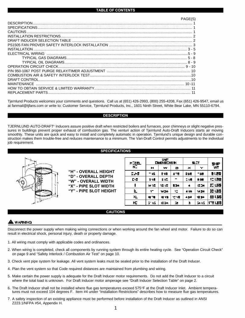
TABLE OF CONTENTS
PAGE(S)DESCRIPTION............................................................................................................................................................... 1SPECIFICATIONS .......................................................................................................................................................... 1CAUTIONS ..................................................................................................................................................................... 1INSTALLATION RESTRICTIONS................................................................................................................................... 2DRAFT INDUCER SELECTION TABLE ........................................................................................................................ 2PS1505 FAN PROVER SAFETY INTERLOCK INSTALLATION ................................................................................... 3INSTALLATION ......................................................................................................................................................... 3 - 5ELECTRICAL WIRING .............................................................................................................................................5 - 9
TYPICAL GAS DIAGRAMS........................................................................................................................ 5 - 8 TYPICAL OIL DIAGRAMS.......................................................................................................................... 8 - 9
OPERATION CIRCUIT CHECK.............................................................................................................................. 9 - 10P/N 950-1067 POST PURGE RELAY/TIMER ADJUSTMENT ................................................................................... 10COMBUSTION AIR & SAFETY INTERLOCK TEST.....................................................................................................10DRAFT CONTROL........................................................................................................................................................10MAINTENANCE .................................................................................................................................................... 10 -11HOW TO OBTAIN SERVICE & LIMITED WARRANTY................................................................................................ 11REPLACEMENT PARTS.............................................................................................................................................. 11
Tjernlund Products welcomes your comments and questions. Call us at (651) 426-2993, (800) 255-4208, Fax (651) 426-9547, email usat [email protected] or write to: Customer Service, Tjernlund Products, Inc., 1601 Ninth Street, White Bear Lake, MN 55110-6794.
DESCRIPTION
TJERNLUND AUTO-DRAFT® Inducers assure positive draft when restricted boilers and furnaces, poor chimneys or slight negative pres-sures in buildings prevent proper exhaust of combustion gas. The venturi action of Tjernlund Auto-Draft Inducers starts air movingsmoothly. These units are quick and easy to install and completely automatic in operation. Tjernlund’s unique design and durable con-struction makes them trouble-free and reduces maintenance to a minimum. The Vari-Draft Control permits adjustments to the individualjob requirement.
SPECIFICATIONS
CAUTIONS
Disconnect the power supply when making wiring connections or when working around the fan wheel and motor. Failure to do so canresult in electrical shock, personal injury, death or property damage.
1. All wiring must comply with applicable codes and ordinances.
2. When wiring is completed, check all components by running system through its entire heating cycle. See “Operation Circuit Check”on page 9 and “Safety Interlock / Combustion Air Test” on page 10.
3. Check vent pipe system for leakage. All vent system leaks must be sealed prior to the installation of the Draft Inducer.
4. Plan the vent system so that Code required distances are maintained from plumbing and wiring.
5. Make certain the power supply is adequate for the Draft Inducer motor requirements. Do not add the Draft Inducer to a circuit where the total load is unknown. For Draft Inducer motor amperage see “Draft Inducer Selection Table” on page 2.
6. The Draft Inducer shall not be installed where flue gas temperatures exceed 575OF at the Draft Inducer Inlet. Ambient tempera-tures must not exceed 104 degrees F. Item #4 under “Installation Restrictions” describes how to measure flue gas temperatures.
7. A safety inspection of an existing appliance must be performed before installation of the Draft Inducer as outlined in ANSI Z223.1/NFPA #54, Appendix H.
1
“H” - OVERALL HEIGHT“D” - OVERALL DEPTH“W” - OVERALL WIDTH“X” - PIPE SLOT WIDTH“Y” - PIPE SLOT HEIGHT
INSTALLATION RESTRICTIONS
Failure to install, maintain and/or operate the Draft Inducer in accordance with manufacturer's instructions may result in conditionswhich can produce bodily injury and property damage.
The Draft Inducer must be installed by a qualified installer in accordance with these instructions and all local codes or in their absencein accordance with the latest editions of The National Fuel Gas Code (NFPA #54), Installation of Fuel Burning Equipment (NFPA 31),Chimneys, Fireplaces, Vents, and Solid Fuel Burning Appliances (NFPA 211), The National Electrical Code (NFPA#70) and theOccupational Safety and Health Act (OSHA) when applicable. Improper installation can create a hazardous condition such as anexplosion, fire, electrical shock or carbon monoxide poisoning resulting in property damage, personal injury or death.
1. The Draft Inducer shall not be used on condensing heating equipment.
2. Oil burning installations and gas-fired units without a draft hood / diverter should include a barometric draft regulator.
3. The Draft Inducer motor shaft must be mounted horizontally to prevent motor bearing wear.
4. The Draft Inducer shall not be installed where flue gas temperatures exceed 575OF at the Draft Inducer Inlet. Ambient room temperatures must not exceed 104 degrees F.
Flue gas temperature verification:
A) Consult appliance manufacturer for temperature of gases at the appliance outlet after dilution by draft hood, draft diverter or barometric draft control.
AND
B) Measure temperature of flue gases at the Draft Inducer inlet at time of installation. Temperature should be measured after appliance and Draft Inducer have operated for at least 10 minutes, allowing flue gas temperature to stabilize.
DRAFT INDUCER SELECTION TABLE
2
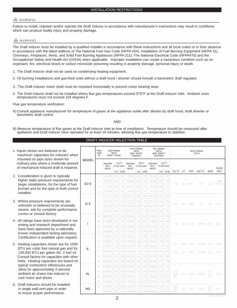
1. Inputs shown are believed to bemaximum capacities for inducers whenmounted on pipe sizes shown forordinary jobs where a moderate amountof mechanical induced draft is required.
2. Consideration is given to typicallyhigher static pressure requirements forlarger installations, for the type of fuelburned and for the type of draft controlinstalled.
3. Where pressure requirements areunknown or believed to be unusually severe, ask for complete performancecurves or consult factory.
4. All ratings have been developed in ourtesting and research department andhave been approved by a nationallyknown independent testing laboratory.Certification is available upon request.
5. Heating capacities shown are for 1000BTU per cubic foot natural gas and for139,000 BTU per gallon No. 2 fuel oil.Consult factory for capacities with otherfuels. Heating capacities are based ontypical combustion efficiencies and allow for approximately 5 percent ambient air drawn into inducer to cool motor and drives.
6. Draft Inducers should be installedin single wall vent pipe in order to insure proper performance.
DJ-3
D-3
I
IL
XL
HD
GAS FIRINGWITH
DRAFT HOOD
MODEL
GAS FIRINGWITH
BAR. DRAFTCONTROL
OIL FIRINGWITH
BAR. DRAFTCONTROL
HEATERBTU
INPUT
HEATERBTU
INPUT
HEATERBTU
INPUTS.P. CFM CFMS.P. CFMS.P.
FLUE GAS FLUE GAS FLUE GAS
ELECTRICALDATA
IN.SIZEPIPE
MODEL PS1505 FAN PROVING SWITCH SAFETY INTERLOCK
The Model PS1505 Fan Proving Switch works on all Tjernlund Draft Inducers to assure adequate draft is present before burner isallowed to fire. The PS1505 complies with burner safety interlock provisions of National Mechanical Codes.
PURPOSEThe PS1505 Fan Prover has been designed to monitor the pressure within the fan housing only. A motor or wheel failure willdecrease housing pressure and deactivate the pressure switch thus preventing combustion.
The PS1505 Fan Prover is not a safety control designed to ensure proper draft or to indicate chimney failure. It is the responsibility ofthe end user to properly maintain the combustion equipment and its chimney or vent. Yearly maintenance and inspection should beconducted by qualified service personnel. Failure to follow such maintenance and inspection procedures may result in generation oftoxic carbon monoxide gas.
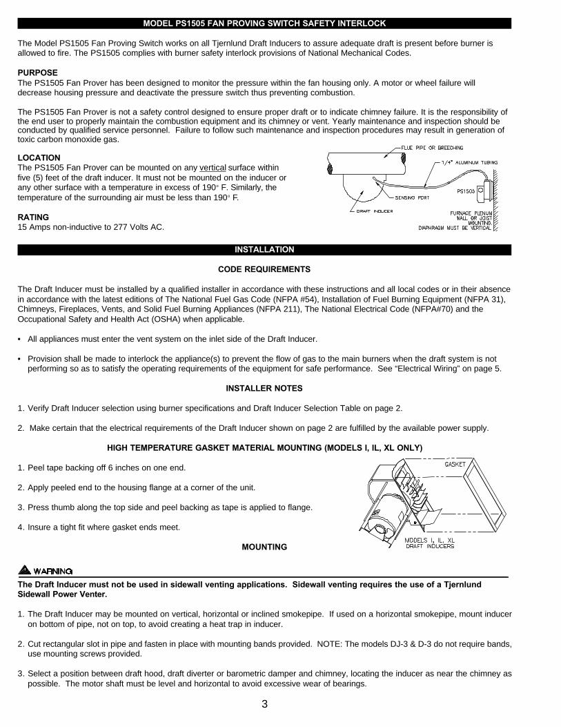
LOCATIONThe PS1505 Fan Prover can be mounted on any vertical surface withinfive (5) feet of the draft inducer. It must not be mounted on the inducer orany other surface with a temperature in excess of 190o F. Similarly, thetemperature of the surrounding air must be less than 190o F.
RATING15 Amps non-inductive to 277 Volts AC.
INSTALLATION
CODE REQUIREMENTS
The Draft Inducer must be installed by a qualified installer in accordance with these instructions and all local codes or in their absencein accordance with the latest editions of The National Fuel Gas Code (NFPA #54), Installation of Fuel Burning Equipment (NFPA 31),Chimneys, Fireplaces, Vents, and Solid Fuel Burning Appliances (NFPA 211), The National Electrical Code (NFPA#70) and theOccupational Safety and Health Act (OSHA) when applicable.
• All appliances must enter the vent system on the inlet side of the Draft Inducer.
• Provision shall be made to interlock the appliance(s) to prevent the flow of gas to the main burners when the draft system is not performing so as to satisfy the operating requirements of the equipment for safe performance. See “Electrical Wiring” on page 5.
INSTALLER NOTES
1. Verify Draft Inducer selection using burner specifications and Draft Inducer Selection Table on page 2.
2. Make certain that the electrical requirements of the Draft Inducer shown on page 2 are fulfilled by the available power supply.
HIGH TEMPERATURE GASKET MATERIAL MOUNTING (MODELS I, IL, XL ONLY)
1. Peel tape backing off 6 inches on one end.
2. Apply peeled end to the housing flange at a corner of the unit.
3. Press thumb along the top side and peel backing as tape is applied to flange.
4. Insure a tight fit where gasket ends meet.
MOUNTING
The Draft Inducer must not be used in sidewall venting applications. Sidewall venting requires the use of a TjernlundSidewall Power Venter.
1. The Draft Inducer may be mounted on vertical, horizontal or inclined smokepipe. If used on a horizontal smokepipe, mount induceron bottom of pipe, not on top, to avoid creating a heat trap in inducer.
2. Cut rectangular slot in pipe and fasten in place with mounting bands provided. NOTE: The models DJ-3 & D-3 do not require bands,use mounting screws provided.
3. Select a position between draft hood, draft diverter or barometric damper and chimney, locating the inducer as near the chimney aspossible. The motor shaft must be level and horizontal to avoid excessive wear of bearings.
3
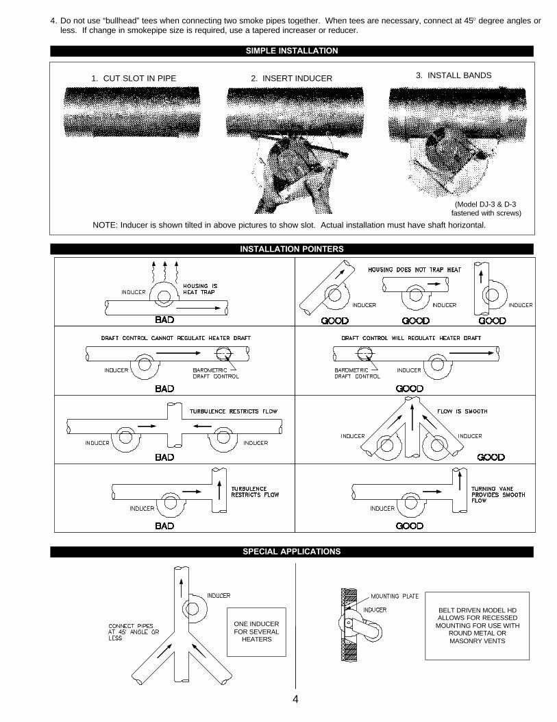
4. Do not use “bullhead” tees when connecting two smoke pipes together. When tees are necessary, connect at 45O degree angles orless. If change in smokepipe size is required, use a tapered increaser or reducer.
4
NOTE: Inducer is shown tilted in above pictures to show slot. Actual installation must have shaft horizontal.
SIMPLE INSTALLATION
INSTALLATION POINTERS
SPECIAL APPLICATIONS
1. CUT SLOT IN PIPE 2. INSERT INDUCER 3. INSTALL BANDS
ONE INDUCERFOR SEVERAL
HEATERS
BELT DRIVEN MODEL HDALLOWS FOR RECESSED
MOUNTING FOR USE WITHROUND METAL OR MASONRY VENTS
(Model DJ-3 & D-3fastened with screws)
ELECTRICAL WIRING
Wiring diagrams are included in these instructions for various draft inducer applications. While it would be impractical to show everyconceivable variation, the ones included will demonstrate sufficient basic techniques for the design and installation of the unusual con-trol system.
The installer should always check the rated capacity of a burner primary control. If the amperage rating of the load contacts is not equal to the sum of all burner components plus that of the inducer motor, an additional isolation relay must be installed as shown in some dia-grams. Draft inducer motor amperage ratings can be found on the “Draft Inducer Selection Table” on bottom of page 2.
The diagrams included show wiring for the standard motors furnished with the inducers. If special voltage motors have been specified,changes in wiring may be necessary.
Wiring diagrams assume all inducer motors (except Model HD) will have 115 volt service. The Model XL is furnished with 115/230 voltmotors. If 230 volt service is required for this unit, consult factory if necessary, for wiring instructions.
The amperage rating of the PS1505 Fan Prover is 15 amps non-inductive to 277 volts AC.
A Post Purge Relay/Timer (P/N 950-1067) should be installed on Draft Inducers when venting Oil Fired Equipment. This will allow theventer to run from 1 to 10 minutes after a heating cycle to purge the vent system of any residual flue gases or oil odors. The Relay/Timercan also be installed on gas installations with extended horizontal vent connectors.
5
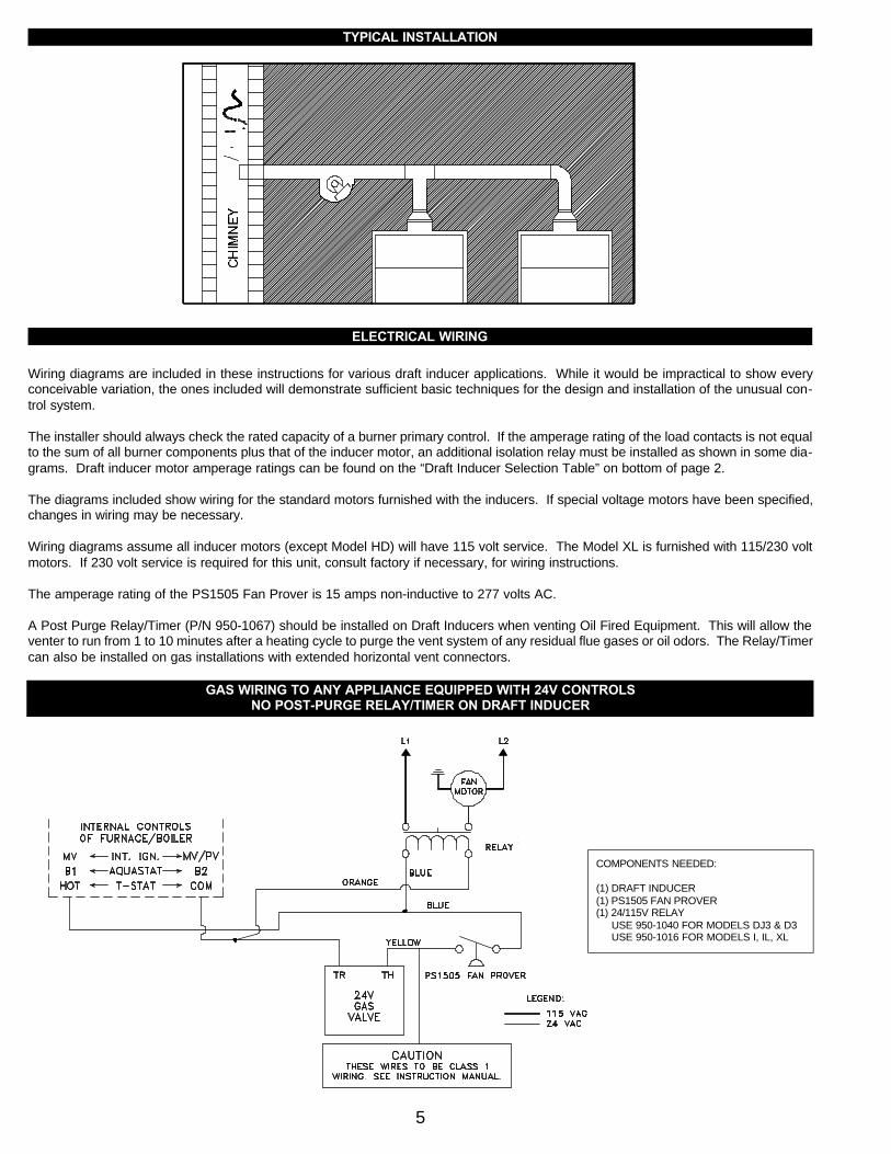
TYPICAL INSTALLATION
GAS WIRING TO ANY APPLIANCE EQUIPPED WITH 24V CONTROLSNO POST-PURGE RELAY/TIMER ON DRAFT INDUCER
COMPONENTS NEEDED:
(1) DRAFT INDUCER(1) PS1505 FAN PROVER(1) 24/115V RELAY
USE 950-1040 FOR MODELS DJ3 & D3USE 950-1016 FOR MODELS I, IL, XL
6
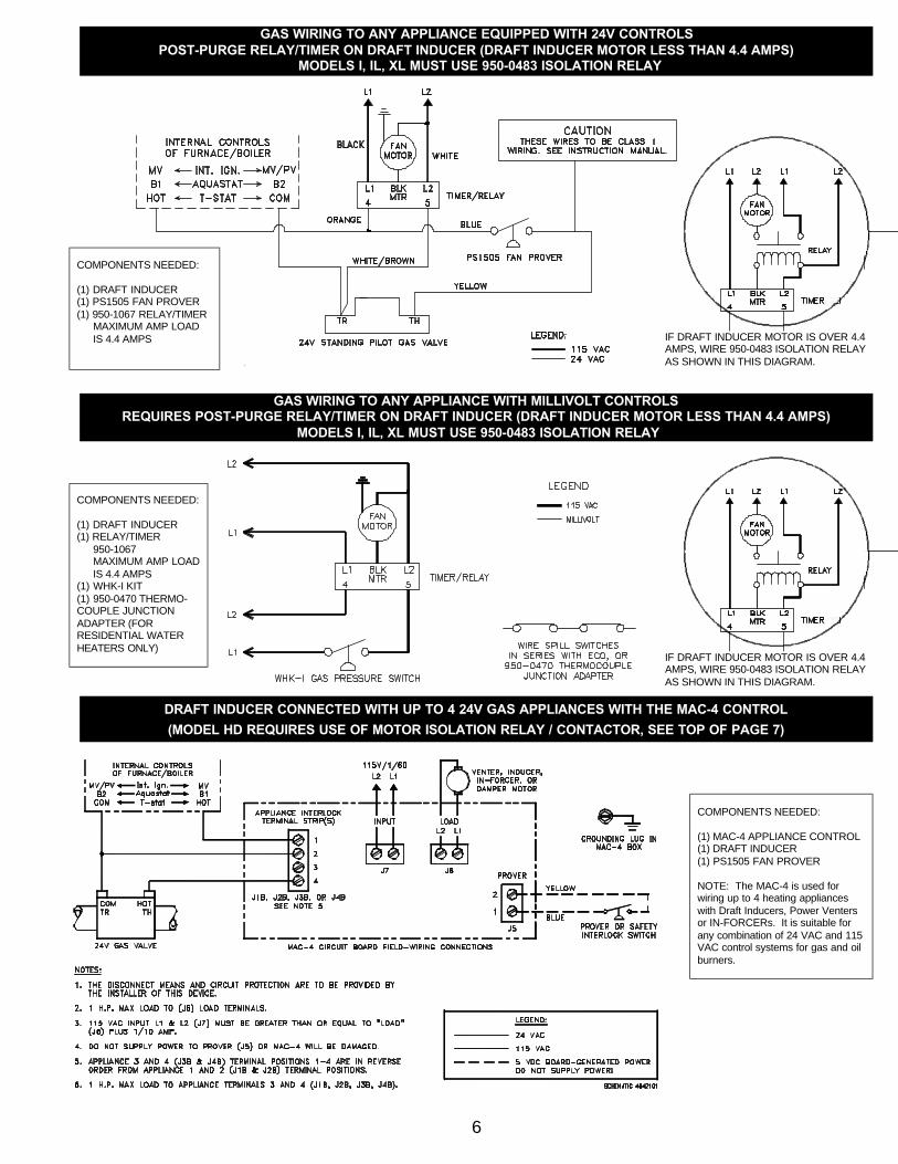
DRAFT INDUCER CONNECTED WITH UP TO 4 24V GAS APPLIANCES WITH THE MAC-4 CONTROL
(MODEL HD REQUIRES USE OF MOTOR ISOLATION RELAY / CONTACTOR, SEE TOP OF PAGE 7)
GAS WIRING TO ANY APPLIANCE EQUIPPED WITH 24V CONTROLSPOST-PURGE RELAY/TIMER ON DRAFT INDUCER (DRAFT INDUCER MOTOR LESS THAN 4.4 AMPS)
MODELS I, IL, XL MUST USE 950-0483 ISOLATION RELAY
GAS WIRING TO ANY APPLIANCE WITH MILLIVOLT CONTROLSREQUIRES POST-PURGE RELAY/TIMER ON DRAFT INDUCER (DRAFT INDUCER MOTOR LESS THAN 4.4 AMPS)
MODELS I, IL, XL MUST USE 950-0483 ISOLATION RELAY
COMPONENTS NEEDED:
(1) DRAFT INDUCER(1) PS1505 FAN PROVER(1) 950-1067 RELAY/TIMER
MAXIMUM AMP LOAD IS 4.4 AMPS
COMPONENTS NEEDED:
(1) DRAFT INDUCER(1) RELAY/TIMER
950-1067MAXIMUM AMP LOADIS 4.4 AMPS
(1) WHK-I KIT(1) 950-0470 THERMO-COUPLE JUNCTION ADAPTER (FOR RESIDENTIAL WATER HEATERS ONLY)
COMPONENTS NEEDED:
(1) MAC-4 APPLIANCE CONTROL(1) DRAFT INDUCER(1) PS1505 FAN PROVER
NOTE: The MAC-4 is used forwiring up to 4 heating applianceswith Draft Inducers, Power Ventersor IN-FORCERs. It is suitable forany combination of 24 VAC and 115VAC control systems for gas and oilburners.
IF DRAFT INDUCER MOTOR IS OVER 4.4AMPS, WIRE 950-0483 ISOLATION RELAY AS SHOWN IN THIS DIAGRAM.
IF DRAFT INDUCER MOTOR IS OVER 4.4AMPS, WIRE 950-0483 ISOLATION RELAY AS SHOWN IN THIS DIAGRAM.

7
DRAFT INDUCER CONNECTED WITH UP TO 4 24V GAS APPLIANCES WITH THE MAC-4 CONTROL
(DRAFT INDUCER MOTOR LOAD GREATER THAN 1 H.P.)
MULTIPLE DRAFT INDUCERS, POWER VENTERS OR IN-FORCERS CONNECTED WITH UP TO 4 24V GAS APPLIANCES (IF INDIVIDUAL OR COMBINED MOTOR LOAD IS OVER 1 H.P. ISOLATION RELAY(S) WILL HAVE TO BE ADDED, SEE ABOVE)
COMPONENTS NEEDED:
(1) MAC-4 APPLIANCE CONTROL(1) DRAFT INDUCER(1) PS1505 FAN PROVER(1) ISOLATION RELAY/CONTACTOR
NOTE: The MAC-4 is used forwiring up to 4 heating applianceswith Draft Inducers, Power Ventersor IN-FORCERs. It is suitable forany combination of 24 VAC and 115VAC control systems for gas and oilburners.
COMPONENTS NEEDED:
(1) MAC-4 APPLIANCE CONTROLDRAFT INDUCER(S)PS1505 FAN PROVER(S)MOTOR ISOLATION RELAY / CONTACTOR(S) IF OVER 1 H.P.
NOTE: The MAC-4 is used forwiring up to 4 heating applianceswith Draft Inducers, Power Ventersor IN-FORCERs. It is suitable forany combination of 24 VAC and 115VAC control systems for gas and oilburners. Wire Fan Prover(s) orLimit(s) in Series with Prover termi-nal block. Do not supply voltage toProver terminal block!
8
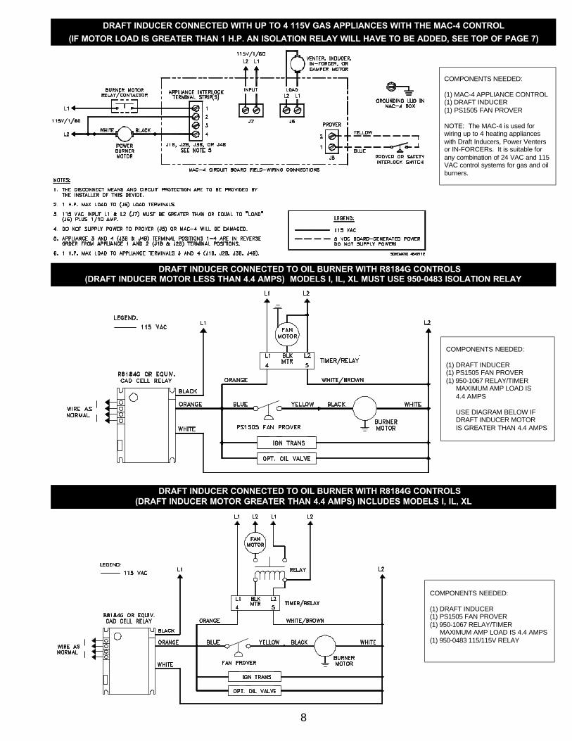
DRAFT INDUCER CONNECTED WITH UP TO 4 115V GAS APPLIANCES WITH THE MAC-4 CONTROL
(IF MOTOR LOAD IS GREATER THAN 1 H.P. AN ISOLATION RELAY WILL HAVE TO BE ADDED, SEE TOP OF PAGE 7)
DRAFT INDUCER CONNECTED TO OIL BURNER WITH R8184G CONTROLS(DRAFT INDUCER MOTOR LESS THAN 4.4 AMPS) MODELS I, IL, XL MUST USE 950-0483 ISOLATION RELAY
DRAFT INDUCER CONNECTED TO OIL BURNER WITH R8184G CONTROLS(DRAFT INDUCER MOTOR GREATER THAN 4.4 AMPS) INCLUDES MODELS I, IL, XL
COMPONENTS NEEDED:
(1) DRAFT INDUCER(1) PS1505 FAN PROVER(1) 950-1067 RELAY/TIMER
MAXIMUM AMP LOAD IS 4.4 AMPS
USE DIAGRAM BELOW IF DRAFT INDUCER MOTOR IS GREATER THAN 4.4 AMPS
COMPONENTS NEEDED:
(1) DRAFT INDUCER(1) PS1505 FAN PROVER(1) 950-1067 RELAY/TIMER
MAXIMUM AMP LOAD IS 4.4 AMPS (1) 950-0483 115/115V RELAY
COMPONENTS NEEDED:
(1) MAC-4 APPLIANCE CONTROL(1) DRAFT INDUCER(1) PS1505 FAN PROVER
NOTE: The MAC-4 is used forwiring up to 4 heating applianceswith Draft Inducers, Power Ventersor IN-FORCERs. It is suitable forany combination of 24 VAC and 115VAC control systems for gas and oilburners.
9
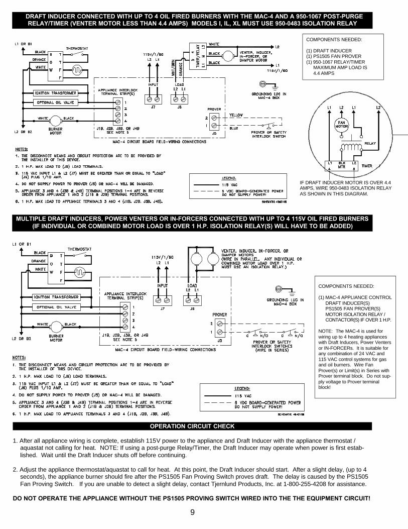
DRAFT INDUCER CONNECTED WITH UP TO 4 OIL FIRED BURNERS WITH THE MAC-4 AND A 950-1067 POST-PURGERELAY/TIMER (VENTER MOTOR LESS THAN 4.4 AMPS) MODELS I, IL, XL MUST USE 950-0483 ISOLATION RELAY
COMPONENTS NEEDED:
(1) DRAFT INDUCER(1) PS1505 FAN PROVER(1) 950-1067 RELAY/TIMER
MAXIMUM AMP LOAD IS 4.4 AMPS
OPERATION CIRCUIT CHECK
1. After all appliance wiring is complete, establish 115V power to the appliance and Draft Inducer with the appliance thermostat / aquastat not calling for heat. NOTE: If using a post-purge Relay/Timer, the Draft Inducer may operate when power is first estab-lished. Wait until the Draft Inducer shuts off before continuing.
2. Adjust the appliance thermostat/aquastat to call for heat. At this point, the Draft Inducer should start. After a slight delay, (up to 4 seconds), the appliance burner should fire after the PS1505 Fan Proving Switch proves draft. The delay is caused by the PS1505 Fan Proving Switch. If you are unable to detect a slight delay, contact Tjernlund Products, Inc. at 1-800-255-4208 for assistance.
DO NOT OPERATE THE APPLIANCE WITHOUT THE PS1505 PROVING SWITCH WIRED INTO THE THE EQUIPMENT CIRCUIT!
MULTIPLE DRAFT INDUCERS, POWER VENTERS OR IN-FORCERS CONNECTED WITH UP TO 4 115V OIL FIRED BURNERS (IF INDIVIDUAL OR COMBINED MOTOR LOAD IS OVER 1 H.P. ISOLATION RELAY(S) WILL HAVE TO BE ADDED)
IF DRAFT INDUCER MOTOR IS OVER 4.4AMPS, WIRE 950-0483 ISOLATION RELAY AS SHOWN IN THIS DIAGRAM.
COMPONENTS NEEDED:
(1) MAC-4 APPLIANCE CONTROLDRAFT INDUCER(S)PS1505 FAN PROVER(S)MOTOR ISOLATION RELAY / CONTACTOR(S) IF OVER 1 H.P.
NOTE: The MAC-4 is used forwiring up to 4 heating applianceswith Draft Inducers, Power Ventersor IN-FORCERs. It is suitable forany combination of 24 VAC and115 VAC control systems for gasand oil burners. Wire FanProver(s) or Limit(s) in Series withProver terminal block. Do not sup-ply voltage to Prover terminalblock!
3. Adjust the appliance thermostat / aquastat so that no heat is required. At this point the Draft Inducer and appliance should shut off. NOTE: If using a P/N 950-1067 post-purge Relay/Timer, the Draft Inducer will continue to run for an adjustable amount of time after the appliance burner shuts off. See “Post Purge Relay/Timer Adjustment” below for post purge adjustment procedure.
P/N 950-1067 POST PURGE RELAY/TIMER ADJUSTMENT
1. Disrupt 115VAC power to the Draft Inducer.
2. The post purge Relay/Timer is marked adjustable delay control. The adjustment is made by turning the small slotted screw. Turn itcounter clockwise to increase the delay, clockwise to decrease the delay. Caution: Use care when adjusting Relay/Timer, over-turning adjustment screw will damage Relay/Timer and void warranty. Nominal adjustment range is 1 to 10 minutes.
COMBUSTION AIR
Adequate combustion air is vital for proper combustion and for safe venting. Likewise, for proper Draft Inducer performance, ade-quate combustion air must be available to the appliance. Many installers assume adequate combustion air is present, especially inolder structures. In some cases this is a false assumption, because many structures have been made "tight" due to weatherization.Size the combustion air opening(s) into the appliance room as outlined NFPA 54/NFPA 211. Tjernlund’s IN-FORCERTM combustion airintake systems provide a convenient, interlocked way to supply combustion air to the utility room. When installing a Draft Inducer it isnot necessary to supply any more combustion air than normally required when conventional venting.
SAFETY INTERLOCK / COMBUSTION AIR TEST
The PS1505 Fan Proving Switch is designed to disable the appliance upon Draft Inducer failure only! It is not designed and cannotreplace, regular vent system inspection, appliance servicing and combustion testing.
1. Close all doors and windows of the building. If the appliance is installed in a utility room or closet, close the entrance door to this room. Close fireplace dampers.
2. Turn on all exhaust fans such as range hoods, bathroom exhausts, whole house fans and dryers to maximum speeds. Do not operate a fan used strictly for Summer exhausting.
3. Following the appliance manufacturer’s instructions, place the appliance in operation, set thermostat for continuous operation.
4. Allow fans and appliance to operate for 5 minutes.
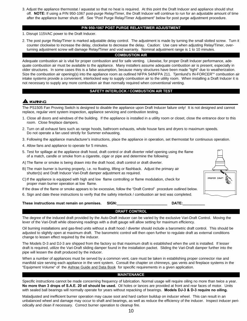
5. Test for spillage at the appliance draft hood, draft control or draft diverter relief opening using the flame of a match, candle or smoke from a cigarette, cigar or pipe and determine the following:
A) The flame or smoke is being drawn into the draft hood, draft control or draft diverter.
B) The main burner is burning properly, i.e. no floating, lifting or flashback. Adjust the primary air shutter(s) and Draft Inducer Vari-Draft damper adjustment as required.
C) If the appliance is equipped with high and low flame controlling or flame modulation, check for proper main burner operation at low flame.
If the draw of the flame or smoke appears to be excessive, follow the “Draft Control” procedure outlined below.
6. Sign and date these instructions to verify that the safety interlock / combustion air test was completed.
These instructions must remain on premises. SIGN:_________________________ DATE:___________
DRAFT CONTROL
The degree of the induced draft provided by the Auto-Draft inducer can be varied by the exclusive Vari-Draft Control. Moving thelever of the Vari-Draft while observing readings with a draft gauge will allow setting for maximum efficiency.
Oil burning installations and gas-fired units without a draft hood / diverter should include a barometric draft control. This should beadjusted to slightly open at maximum draft. The barometric control will then open further to regulate draft as external conditionschange to lessen effect required by the inducer.
The Models D-3 and DJ-3 are shipped from the factory so that maximum draft is established when the unit is installed. If lesser draft is required, utilize the Vari-Draft sliding damper found in the installation packet. Sliding the Vari-Draft damper further into thepipe will lessen the draft produced by the inducer.
When a number of appliances must be served by a common vent, care must be taken in establishing proper connector rise and manifold size serving each appliance in the vent system. Consult the chapter on chimneys, gas vents and fireplace systems in the “Equipment Volume“ of the Ashrae Guide and Data Book for specific requirements in a given application.
MAINTENANCE
Specific instructions cannot be made concerning frequency of lubrication. Normal usage will require oiling no more than twice a year.No more than 3 drops of S.A.E. 20 oil should be used. Oil holes or lances are provided at front and rear faces of motor. Unitswith sealed ball bearings will normally operate for years without repacking of bearings. Models DJ-3 & D-3 require no oiling.
Maladjusted and inefficient burner operation may cause soot and hard carbon buildup on inducer wheel. This can result in an unbalanced wheel and damage may occur to shaft and bearings, as well as reduce the efficiency of the inducer. Inspect inducer peri-odically and clean if necessary. Correct burner operation to cleanup fire.
10
MODEL HD ONLYBelts should be checked and adjusted at least once a year. Replace worn belts immediately. When either belt needs replacement, amatched pair of new belts must be installed.
HOW TO OBTAIN SERVICE ASSISTANCE
1. If you have any questions about your Draft Inducer or if it requires adjustment, repair or routine maintenance, we suggest thatyou contact your installer, plumbing contractor or service agency.
2. If you require technical information contact Tjernlund Products, Inc. at 1-800-255-4208.
When contacting Tjernlund Products, Inc., please have the following information available:
1. Model number of the Draft Inducer 2. Name and address of installer and service agency3. Date of original installation and dates any service work was performed4. Details of the problem
LIMITED PARTS WARRANTY AND CLAIM PROCEDURE
Tjernlund Products, Inc. warrants the components of its products for one year from date of installation. This warranty covers defectsin material and workmanship. This warranty does not cover normal maintenance, transportation or installation charges for replace-ment parts or any other service calls or repairs. Products that are tampered with, damaged, installed improperly, wired incorrectly ordefective due to malfunctioning appliances are not covered under this warranty. This warranty DOES NOT cover the complete DraftInducer if it is operable, except for the defective part.
Tjernlund Products, Inc. will issue credit to the original distributor or provide a free part to replace one that becomes defective duringthe one year warranty period. If the part is over 18 months old, proof of date of the installation in the form of the contractor sales /installation receipt is necessary to prove the unit has been in service for under one year. All receipts should include the date code ofthe Draft Inducer to ensure that the defective component corresponds with the complete unit. This will help preclude possible creditrefusal.
After the faulty component is determined, return it to your Tjernlund distributor for replacement. Please include Draft Inducer date code component was taken from. The date code is located on the electrical box coverplate or back of motor mount plate. If DraftInducer date code is older than 18 months you will need to provide a copy of the original installation receipt to your distributor. Creditor replacement will only be issued to a Tjernlund distributor after the defective part has been returned prepaid to Tjernlund.
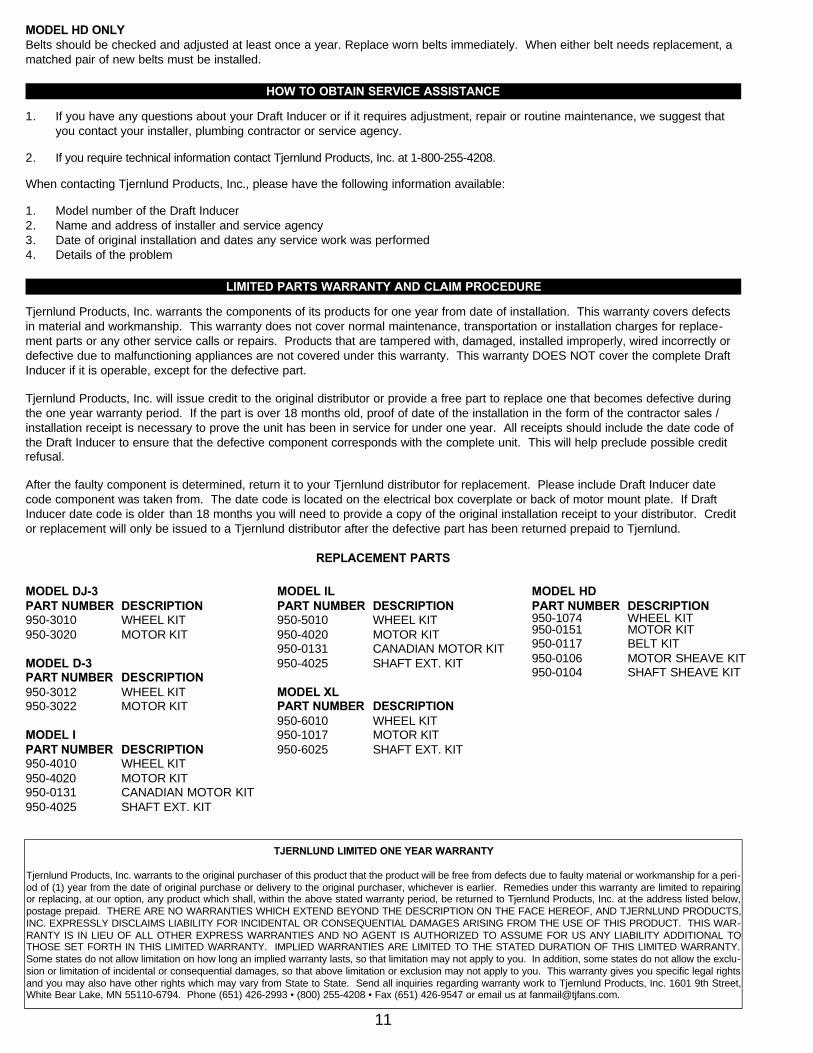
REPLACEMENT PARTS
11
TJERNLUND LIMITED ONE YEAR WARRANTY
Tjernlund Products, Inc. warrants to the original purchaser of this product that the product will be free from defects due to faulty material or workmanship for a peri-od of (1) year from the date of original purchase or delivery to the original purchaser, whichever is earlier. Remedies under this warranty are limited to repairingor replacing, at our option, any product which shall, within the above stated warranty period, be returned to Tjernlund Products, Inc. at the address listed below,postage prepaid. THERE ARE NO WARRANTIES WHICH EXTEND BEYOND THE DESCRIPTION ON THE FACE HEREOF, AND TJERNLUND PRODUCTS,INC. EXPRESSLY DISCLAIMS LIABILITY FOR INCIDENTAL OR CONSEQUENTIAL DAMAGES ARISING FROM THE USE OF THIS PRODUCT. THIS WAR-RANTY IS IN LIEU OF ALL OTHER EXPRESS WARRANTIES AND NO AGENT IS AUTHORIZED TO ASSUME FOR US ANY LIABILITY ADDITIONAL TOTHOSE SET FORTH IN THIS LIMITED WARRANTY. IMPLIED WARRANTIES ARE LIMITED TO THE STATED DURATION OF THIS LIMITED WARRANTY.Some states do not allow limitation on how long an implied warranty lasts, so that limitation may not apply to you. In addition, some states do not allow the exclu-sion or limitation of incidental or consequential damages, so that above limitation or exclusion may not apply to you. This warranty gives you specific legal rightsand you may also have other rights which may vary from State to State. Send all inquiries regarding warranty work to Tjernlund Products, Inc. 1601 9th Street,White Bear Lake, MN 55110-6794. Phone (651) 426-2993 • (800) 255-4208 • Fax (651) 426-9547 or email us at [email protected].
MODEL DJ-3 PART NUMBER DESCRIPTION 950-3010 WHEEL KIT950-3020 MOTOR KIT
MODEL D-3 PART NUMBER DESCRIPTION950-3012 WHEEL KIT950-3022 MOTOR KIT
MODEL I PART NUMBER DESCRIPTION950-4010 WHEEL KIT950-4020 MOTOR KIT950-0131 CANADIAN MOTOR KIT950-4025 SHAFT EXT. KIT
MODEL IL PART NUMBER DESCRIPTION950-5010 WHEEL KIT950-4020 MOTOR KIT950-0131 CANADIAN MOTOR KIT950-4025 SHAFT EXT. KIT
MODEL XL PART NUMBER DESCRIPTION950-6010 WHEEL KIT950-1017 MOTOR KIT 950-6025 SHAFT EXT. KIT
MODEL HD PART NUMBER DESCRIPTION950-1074 WHEEL KIT950-0151 MOTOR KIT950-0117 BELT KIT 950-0106 MOTOR SHEAVE KIT950-0104 SHAFT SHEAVE KIT