augmented reality and its practical use - diva...
TRANSCRIPT

UPTEC IT 11 013
Examensarbete 30 hpAugusti 2011
Augmented reality and its practical use
Alexander Nordfelth

Teknisk- naturvetenskaplig fakultet UTH-enheten Besöksadress: Ångströmlaboratoriet Lägerhyddsvägen 1 Hus 4, Plan 0 Postadress: Box 536 751 21 Uppsala Telefon: 018 – 471 30 03 Telefax: 018 – 471 30 00 Hemsida: http://www.teknat.uu.se/student
Abstract
Augmented reality and its practical use
Alexander Nordfelth
Augmented reality is the next step in human/computer interaction. The purpose of this thesis is to further investigate how this can be used to aid in navigation and exploration. This thesis presents a platform-independent framework for outdoor augmented reality. Several interfaces were developed so an evaluation could be made. These interfaces are implemented from scratch since interfaces for augmented reality is very hard to imagine or evaluate without using them. The interfaces proposed is shown to provide a completely new level of augmentation for the user, which was the goal.
Tryckt av: Reprocentralen ITC
Sponsor: Ascom Network Testing ABISSN: 1401-5749, UPTEC IT 11 013Examinator: Anders JanssonÄmnesgranskare: Lars OestreicherHandledare: Adrian Jakobsson

Contents
Glossary 7
1 Introduction 8
2 Previous work 9
3 Sensors 103.1 Camera . . . . . . . . . . . . . . . . . . . . . . . . . . . . . . 103.2 3-axis gyroscope . . . . . . . . . . . . . . . . . . . . . . . . . . 113.3 3-axis magnetometer . . . . . . . . . . . . . . . . . . . . . . . 113.4 3-axis accelerometer . . . . . . . . . . . . . . . . . . . . . . . . 113.5 GPS . . . . . . . . . . . . . . . . . . . . . . . . . . . . . . . . 11
4 Design 114.1 Perspective map . . . . . . . . . . . . . . . . . . . . . . . . . . 124.2 Height-map . . . . . . . . . . . . . . . . . . . . . . . . . . . . 134.3 Radar . . . . . . . . . . . . . . . . . . . . . . . . . . . . . . . 144.4 Directions . . . . . . . . . . . . . . . . . . . . . . . . . . . . . 154.5 Points of interest . . . . . . . . . . . . . . . . . . . . . . . . . 164.6 Evaluation . . . . . . . . . . . . . . . . . . . . . . . . . . . . . 17
5 Architecture 185.1 Scene-graph . . . . . . . . . . . . . . . . . . . . . . . . . . . . 185.2 Platform independence . . . . . . . . . . . . . . . . . . . . . . 185.3 Modeling . . . . . . . . . . . . . . . . . . . . . . . . . . . . . . 185.4 UML . . . . . . . . . . . . . . . . . . . . . . . . . . . . . . . . 19
5.4.1 Core . . . . . . . . . . . . . . . . . . . . . . . . . . . . 195.4.2 Graphics . . . . . . . . . . . . . . . . . . . . . . . . . . 195.4.3 Sensors . . . . . . . . . . . . . . . . . . . . . . . . . . . 205.4.4 Augmented reality . . . . . . . . . . . . . . . . . . . . 21
6 Mathematical overview 226.1 Introduction . . . . . . . . . . . . . . . . . . . . . . . . . . . . 226.2 Theory (in-depth) . . . . . . . . . . . . . . . . . . . . . . . . . 22
6.2.1 Position calculations . . . . . . . . . . . . . . . . . . . 226.2.2 Orientation calculations . . . . . . . . . . . . . . . . . 24
CONTENTS
7 Implementation 277.1 Platforms . . . . . . . . . . . . . . . . . . . . . . . . . . . . . 27
7.1.1 Device . . . . . . . . . . . . . . . . . . . . . . . . . . . 277.1.2 Video driver . . . . . . . . . . . . . . . . . . . . . . . . 277.1.3 Sensors . . . . . . . . . . . . . . . . . . . . . . . . . . . 28
7.2 Libraries . . . . . . . . . . . . . . . . . . . . . . . . . . . . . . 297.2.1 libcurl . . . . . . . . . . . . . . . . . . . . . . . . . . . 297.2.2 µSTL . . . . . . . . . . . . . . . . . . . . . . . . . . . 297.2.3 tinyxml . . . . . . . . . . . . . . . . . . . . . . . . . . 29
7.3 Experimental implementation . . . . . . . . . . . . . . . . . . 297.3.1 The map . . . . . . . . . . . . . . . . . . . . . . . . . . 297.3.2 Perspective map . . . . . . . . . . . . . . . . . . . . . . 307.3.3 Height-map . . . . . . . . . . . . . . . . . . . . . . . . 307.3.4 Radar . . . . . . . . . . . . . . . . . . . . . . . . . . . 307.3.5 Directions . . . . . . . . . . . . . . . . . . . . . . . . . 31
8 Future work 318.1 Filtering . . . . . . . . . . . . . . . . . . . . . . . . . . . . . . 328.2 Functionality . . . . . . . . . . . . . . . . . . . . . . . . . . . 32
9 Conclusion 33
Bibliography 35
Appendices 36
A Prototype 36A.1 Initialization . . . . . . . . . . . . . . . . . . . . . . . . . . . . 36A.2 Rendering . . . . . . . . . . . . . . . . . . . . . . . . . . . . . 38
6
GLOSSARY
Glossary
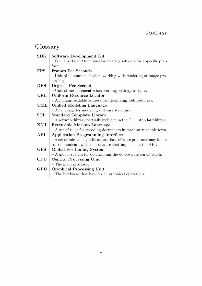
SDK Software Development Kit– Frameworks and functions for creating software for a specific plat-form.
FPS Frames Per Seconds– Unit of measurement when working with rendering or image pro-cessing.
DPS Degrees Per Second– Unit of measurement when working with gyroscopes.
URL Uniform Resource Locator– A human-readable address for identifying web resources.
UML Unified Modeling Language– A language for modeling software structure.
STL Standard Template Library– A software library partially included in the C++ standard library.
XML Extensible Markup Language– A set of rules for encoding documents in machine-readable form.
API Application Programming Interface– A set of rules and specifications that software programs may followto communicate with the software that implements the API.
GPS Global Positioning System– A global system for determining the device position on earth.
CPU Central Processing Unit– The main processor.
GPU Graphical Processing Unit– The hardware that handles all graphical operations.
7
1 INTRODUCTION
1 Introduction
Ascom Network Testing AB is a company that provides hardware and soft-ware to companies that requires the most advanced tools available today.Their main goal is to provide industry-leading tools for troubleshooting, ver-ification, optimization and maintenance of wireless networks. Ascoms toolsand software is used by some of the biggest mobile network operators to date.
Ascom always tries to improve the usability of their tools and has beeninterested in new ways to interact and present their information for sometime, specifically to see if augmented reality is something that they wouldwant to use in their products.
Augmented reality for mobile platforms has seen an incredible rise in popu-larity in the last few years. Part of that rise is due to the Apple iPhone 3GS,which came in mid-2009 and had all the required sensors built right in. Italso had a mature SDK that made it easier for the developer to add contenton top of the camera view.
Augmented reality as a concept on the other hand is much older. Aug-mented reality dates back as far as the 1960’s when M. L. Heilig [1] filed for apatent regarding his Sensorama that could simulate visuals, audio, sense andsmell. Though wearable augmented reality has not been feasible until thelast decade since it required expensive equipment paired with fast computers.Now almost all mobile phones have the required sensors for augmented real-ity to work, and as the processor and graphics chip become more powerful,so will augmented reality.
The purpose of this thesis is to investigate how wearable augmented real-ity can be used to aid in navigation and exploration. To do this investigationsome applications had to be developed, but it was realized early that therewere no suitable framework for augmented reality. Focus was then shiftedtowards creating a framework, which would later be used to create the pro-totype. The framework is described from an architectural viewpoint and theresulting interfaces are discussed in detail.
Some employees of Ascom Network Testing AB were given a copy of theprototype for evaluation. Their comments are presented at the end of thethesis.
8
2 PREVIOUS WORK
2 Previous work
Mobile augmented reality has not been around until the late 90’s since itrequired expensive sensors and powerful processors. However, it is not untilthe last couple of years that the research has dramatically increased alongwith its popularity.
The subjects that is most sought after is the so-called marker-less aug-mented reality, which would allow an augmented reality-device to track anyobject solely based on its natural features. It is quite possible to do on amobile device, but it would require some optimizations to run in real-timetoday. They usually run at ∼10 FPS, which is quite low, and would result inslow rendering. Rendering at around 30 FPS is sufficient for smooth results.
The amount of previous work that covers the same subject is limitedsince the goal is to further explore how mobile augmented reality can beused. However, inspiration has been found through various papers. Some ofthe inspiration is covered here along with some notes regarding their future.
Inspiration One of the main inspirational sources for this thesis is the workof Handheld Augmented Reality @ Graz University of Technology. Theirpaper, Real-time Panoramic Mapping and Tracking on Mobile Phones [2],presents a panoramic tracking method that has several interesting properties:
• Real-time
• Marker-less (though it doesn’t track objects)
• Orientation compensation
Their tracker provides a general tracking method which tracks naturalfeatures of the images that the camera captures, these features then createsa reference for their tracker so it can aid with the orientation calculation.Their tracker can even produce real-time panoramas given that the user isstationary.
Their tracker is not incorporated here because of processing power, eventhough it is possible to run it at ∼30 FPS. But there still has to be process-ing power left for the other advanced features that are presented in section(4). The other part is that is not suited for moving devices since the initialtracking is quite slow, which has to be performed on each position update.Their tracker is on the other hand something that will be used in the future,when the processing power of mobile devices has increased. Alternatively,when the computationally expensive parts can be performed on the GPU.
9
3 SENSORS
Another very interesting paper is Parallel Tracking and Mapping for SmallAR Workspaces [3] which proposes a high-performance marker-less trackerthat is capable of tracking and mapping at the same time. This trackeropens up for some very interesting augmented reality applications since itallows the developer to augment almost anything. This paper does how-ever also fall to the same problem as the previous paper – computationallyexpensive.
3 Sensors
The framework proposed in this thesis uses a mobile device to fetch as muchdata as possible from a set of sensors, which is later used to augment thereality for the user. A mobile device is used since these devices are very cheapand comes with a impressive set of sensors, even though they certainly aren’tthe most precise instruments, they still provide values that are sufficient foraugmented reality. The device used in this prototype is an Apple iPhone 4,which has the following sensors:
• Camera
• 3-axis gyroscope
• 3-axis magnetometer
• 3-axis accelerometer
• GPS
The framework takes the output of the gyroscope, magnetometer and ac-celerometer and fuses them to get a single estimate of the device’s orientation.More on that in section 6.2.2.
3.1 Camera
The camera used in this thesis is only used to display what is in front of theuser. Originally there were plans to incorporate motion tracking using thecamera, but such calculations is quite heavy and would at this state disturbthe overall augmentation. Another use for the camera is to include supportfor in-door augmented reality, which makes heavy use of the built-in camera.
10
4 DESIGN
3.2 3-axis gyroscope
The 3-axis gyroscope found in Apple’s iPhone 4 is a L3G4200D from STMi-croelectronics1. A gyroscope works by measuring rotation rates, but theseare prune to drift, even though they are quite precise. This drift is specifiedin the datasheet to: 0.03 dps√
Hz.
3.3 3-axis magnetometer
The 3-axis magnetometer (or digital compass) found in Apple’s iPhone 4is a AKM8975 from AKM Semiconductor2. The magnetometer gives thedirection due north that the device is pointing. These sensors are quiteprecise but have a low update-frequency.
3.4 3-axis accelerometer
The 3-axis accelerometer found in Apple’s iPhone 4 is a LIS331DLH fromSTMicroelectronics3. The accelerometer works by measuring the accelerationon the device, in three axes. The accelerometer drift is quite low: 218 µg√
Hz.
3.5 GPS
The GPS chip found in Apple’s iPhone 4 is a BCM7450 from Broadcom4.The GPS chip allows for position updates at up to 2Hz.
4 Design
The main idea behind the thesis was to research how augmented reality can beapplied in new and interesting ways. To be able to research this on a scientificlevel would require extensive experience in designing interfaces. Instead, thisthesis proposes a platform-independent framework for augmented reality-applications to skip the step of designing the interface on paper, and movedirectly to the prototyping stage. This approach is better suited due to theadvanced display properties of augmented reality-applications.
1http://www.st.com/internet/com/TECHNICAL RESOURCES/TECHNICALLITERATURE/DATASHEET/CD00265057.pdf
2http://www.asahi-kasei.co.jp/akm/en/product/ak8975b/ak8975b.html3http://www.st.com/stonline/products/literature/ds/15094/lis331dlh.pdf4http://www.broadcom.com/products/GPS/GPS-Silicon-Solutions/BCM4750
11
4 DESIGN
Five interfaces are implemented in the prototype presented with this the-sis. These aims to present the user with the information provided by a pointof interest, or in other ways augment the users reality.
4.1 Perspective map
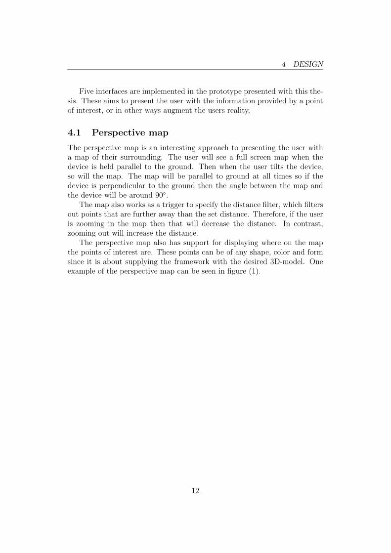
The perspective map is an interesting approach to presenting the user witha map of their surrounding. The user will see a full screen map when thedevice is held parallel to the ground. Then when the user tilts the device,so will the map. The map will be parallel to ground at all times so if thedevice is perpendicular to the ground then the angle between the map andthe device will be around 90◦.
The map also works as a trigger to specify the distance filter, which filtersout points that are further away than the set distance. Therefore, if the useris zooming in the map then that will decrease the distance. In contrast,zooming out will increase the distance.
The perspective map also has support for displaying where on the mapthe points of interest are. These points can be of any shape, color and formsince it is about supplying the framework with the desired 3D-model. Oneexample of the perspective map can be seen in figure (1).
12
4 DESIGN
(a) Device is parallel to the ground. Re-sult: 2D map
(b) Device is tilted upward. Result: 3Dmap
Figure 1: Perspective map example with some points of interest and the userposition.
4.2 Height-map
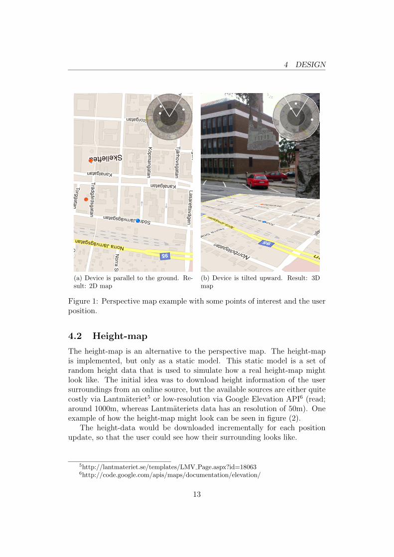
The height-map is an alternative to the perspective map. The height-mapis implemented, but only as a static model. This static model is a set ofrandom height data that is used to simulate how a real height-map mightlook like. The initial idea was to download height information of the usersurroundings from an online source, but the available sources are either quitecostly via Lantmateriet5 or low-resolution via Google Elevation API6 (read;around 1000m, whereas Lantmateriets data has an resolution of 50m). Oneexample of how the height-map might look can be seen in figure (2).
The height-data would be downloaded incrementally for each positionupdate, so that the user could see how their surrounding looks like.
5http://lantmateriet.se/templates/LMV Page.aspx?id=180636http://code.google.com/apis/maps/documentation/elevation/
13
4 DESIGN
Figure 2: This height-map is a static model, but it gives a good estimate onhow it would look given real data.
4.3 Radar
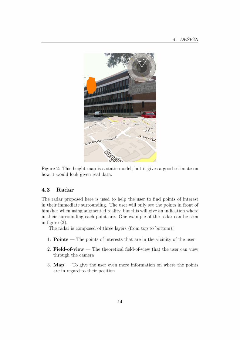
The radar proposed here is used to help the user to find points of interestin their immediate surrounding. The user will only see the points in front ofhim/her when using augmented reality, but this will give an indication wherein their surrounding each point are. One example of the radar can be seenin figure (3).
The radar is composed of three layers (from top to bottom):
1. Points — The points of interests that are in the vicinity of the user
2. Field-of-view — The theoretical field-of-view that the user can viewthrough the camera
3. Map — To give the user even more information on where the pointsare in regard to their position
14
4 DESIGN
Figure 3: The radar resides in the upper-right corner, where the user can seepoints of interest relative to their location.
4.4 Directions
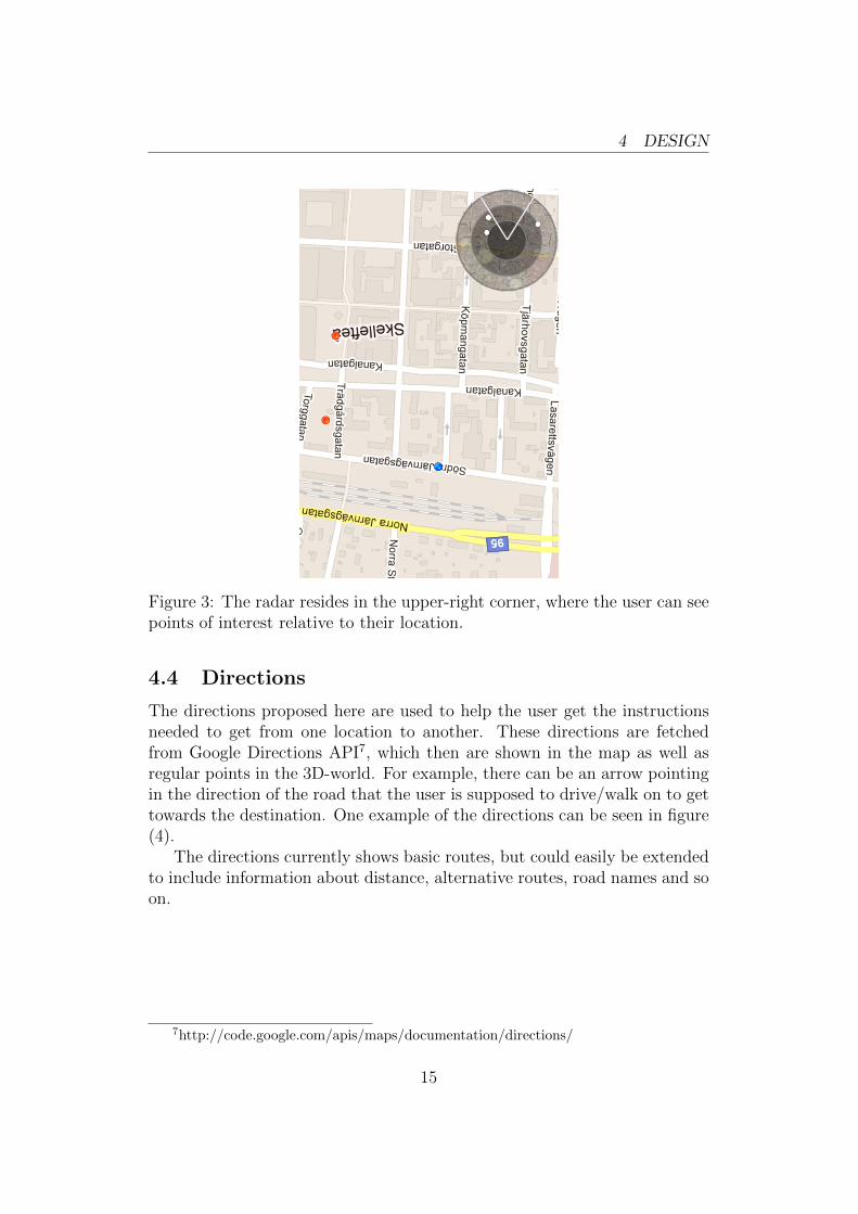
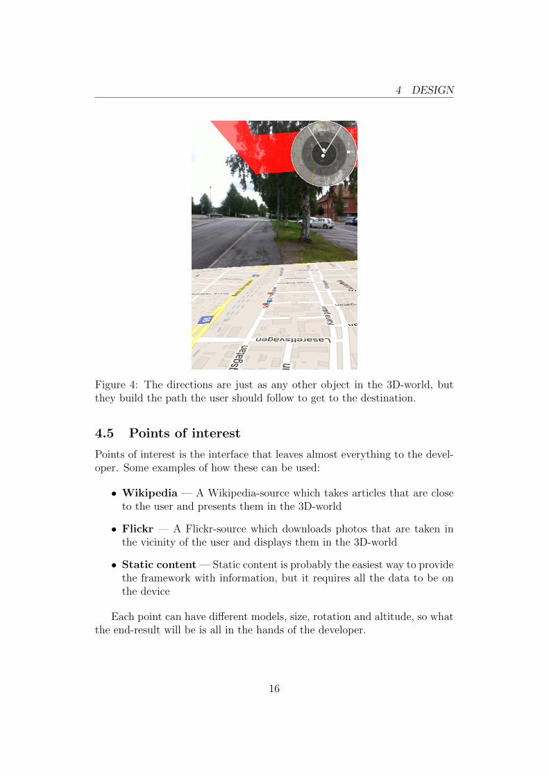
The directions proposed here are used to help the user get the instructionsneeded to get from one location to another. These directions are fetchedfrom Google Directions API7, which then are shown in the map as well asregular points in the 3D-world. For example, there can be an arrow pointingin the direction of the road that the user is supposed to drive/walk on to gettowards the destination. One example of the directions can be seen in figure(4).
The directions currently shows basic routes, but could easily be extendedto include information about distance, alternative routes, road names and soon.
7http://code.google.com/apis/maps/documentation/directions/
15
4 DESIGN
Figure 4: The directions are just as any other object in the 3D-world, butthey build the path the user should follow to get to the destination.
4.5 Points of interest
Points of interest is the interface that leaves almost everything to the devel-oper. Some examples of how these can be used:
• Wikipedia — A Wikipedia-source which takes articles that are closeto the user and presents them in the 3D-world
• Flickr — A Flickr-source which downloads photos that are taken inthe vicinity of the user and displays them in the 3D-world
• Static content — Static content is probably the easiest way to providethe framework with information, but it requires all the data to be onthe device
Each point can have different models, size, rotation and altitude, so whatthe end-result will be is all in the hands of the developer.
16

4 DESIGN
4.6 Evaluation
Several employees at Ascom Network Testing AB were given a copy of theprototype, which they summarized as below.
It was impressive to see how fast the prototype was able to visu-alize new ideas, and that it truly functions as a canvas for explo-ration. Seeing the increased complexity and the sheer amount ofdata that users are becoming exposed to, research into this kindof intuitive visualization is important. The purpose of the datais to describe reality and in the case of mobile technology, the re-ality is often not perceivable to humans. Superimposing abstractinformation into reality makes it easier to see a connection andunderstand the environment around you. This works particularlywell in a mobile testing scenario where the environment is a keyfactor to the operation of the device and surrounding network.
- Ascom Network Testing AB
17
5 ARCHITECTURE
5 Architecture
The architecture used for the framework is crafted around how developersmight want to use the framework. The need for flexibility is very importantsince the framework is supposed to be used as a tool for experimenting, thusgiving the developer the freedom to do that what they want.
5.1 Scene-graph
The methodology used in the framework is called scene-graph and it datesback to the late-90’s when 3D-engines were rising in popularity. Scene-graphsare a way to define scenes in a hierarchal manner, so that objects (representedas nodes in the graph) are related to each other with a parent/children-relationship. This kind of representation makes the scene-management mucheasier to work with since complex objects can be built by adding simplerobjects as children of the complex node.
5.2 Platform independence
Great care was taken during the design of the framework since the goal ofthe framework was to provide a platform independent solution for mobileaugmented reality. The framework is written in pure C/C++ that imple-ments either pure platform independent classes and functions or providesinterface-classes that should be implemented on each platform. The frame-work also makes use of several libraries for different functionality, all of whichare platform independent.
5.3 Modeling
To model the architecture a general modeling language is used. The UnifiedModeling Language8 (UML) was chosen due to its popularity and standardformat. The created model is a simplified version of the framework, but givesa good estimate on how everything is connected.
Reading guide The model consists of four separate parts, one part for eachmodule of the framework. Each part shows a number of rectangles, whichindicates a class or interface, and depending on relationships or dependenciesto other classes, one or more lines can stretch from one rectangle to another.A dotted line indicates that the class where the line originates from is a
8http://www.uml.org/
18
5 ARCHITECTURE
dependency of the target class. A solid line indicates that the class wherethe line originates from is a superclass of the target class, where the rectanglein the corner of the target class indicates the superclass (for clarification).
5.4 UML
5.4.1 Core
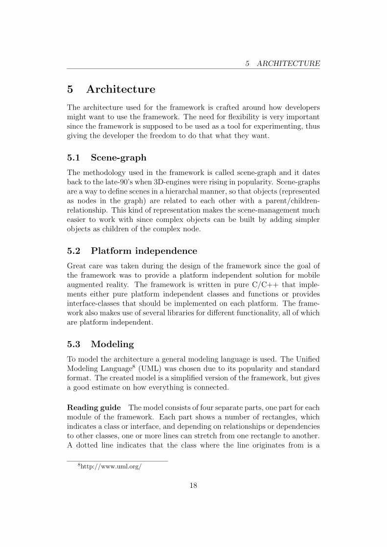
The Core-module implements basic functionality such as vectors, matrices,timers, network and so on. Figure (5) shows each class that the Core-moduleconsists of, and how they relate to each other.
Figure 5: UML-layout of the Core-module.
5.4.2 Graphics
The Graphics-module implements all graphics-related functionality such asrendering, transformation, image loading and so on. Figure (6) shows eachclass that the Graphics-module consists of, and how they relate to each other.
19

5 ARCHITECTURE
Figure 6: UML-layout of the Graphics-module.
5.4.3 Sensors
The Sensors-module implements all sensor-related functionality such as start-ing/stopping sensors, reading sensor values, sensor fusion and so on. Figure(7) shows each class that the Sensors-module consists of, and how they relateto each other.
Figure 7: UML-layout of the Sensors-module.
20

5 ARCHITECTURE
5.4.4 Augmented reality
The Augmented reality-module implements all functions that are related toaugmented reality. Figure (8) shows some nodes that the AR-module consistsof, and how they relate to each other.
Figure 8: UML-layout of the AR-module.
21
6 MATHEMATICAL OVERVIEW
6 Mathematical overview
The purpose of this section is to provide a brief description on how theframework uses the sensor outputs to be able to augment the reality. Thein-depth description can be found in section (6.2) and forward.
6.1 Introduction
This thesis is focused on position-based outdoor augmented reality. To beable to present the augmentation in a user-friendly way requires some pro-cessing of the sensor outputs. This processing does of course depend on thetype of augmentation that is sought after, but based on the goal presentedhere, requires the framework to perform position- and orientation-based pro-cessing.
The orientation-based processing is needed to get an absolute orientationrelative to earth. The position-based processing is then needed to calculatethe distance and bearing to each point. This information is then used toposition the points in the framework’s internal coordinate system so the usercan be presented with the augmentation relative to the device.
6.2 Theory (in-depth)
Outdoor augmented reality relies heavily on the output of the device’s sensor.These sensors make it possible for the framework to estimate the deviceposition and orientation. There are two types of calculations that has tobe done before the framework has enough knowledge to place each point ofinterest, and these are:
1. Position-based calculations
2. Orientation-based calculations
6.2.1 Position calculations
Outdoor augmented reality is all about filtering away information that isn’twithin the range of the user specified radius. This filtering is done by cal-culating the distances to each point of interest, which can be done using theHaversine formula. The second step is to calculate the offset from the de-vice’s bearing to the point’s initial bearing, so the framework can filter outif the point is in the device’s field-of-view. The initial bearing of each pointcan be calculated using the formula described in section (6.2.1).
22
6 MATHEMATICAL OVERVIEW
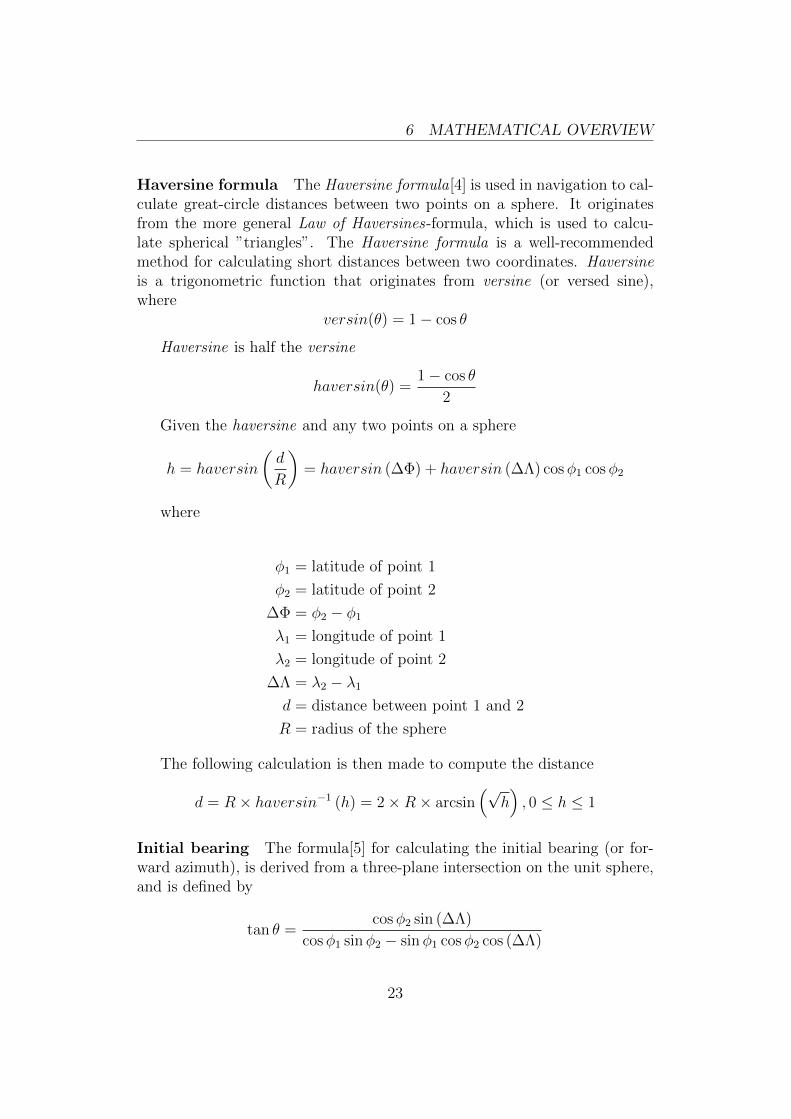
Haversine formula The Haversine formula[4] is used in navigation to cal-culate great-circle distances between two points on a sphere. It originatesfrom the more general Law of Haversines-formula, which is used to calcu-late spherical ”triangles”. The Haversine formula is a well-recommendedmethod for calculating short distances between two coordinates. Haversineis a trigonometric function that originates from versine (or versed sine),where
versin(θ) = 1− cos θ
Haversine is half the versine
haversin(θ) =1− cos θ
2
Given the haversine and any two points on a sphere
h = haversin
(d
R
)= haversin (∆Φ) + haversin (∆Λ) cosφ1 cosφ2
where
φ1 = latitude of point 1
φ2 = latitude of point 2
∆Φ = φ2 − φ1
λ1 = longitude of point 1
λ2 = longitude of point 2
∆Λ = λ2 − λ1d = distance between point 1 and 2
R = radius of the sphere
The following calculation is then made to compute the distance
d = R× haversin−1 (h) = 2×R× arcsin(√
h), 0 ≤ h ≤ 1
Initial bearing The formula[5] for calculating the initial bearing (or for-ward azimuth), is derived from a three-plane intersection on the unit sphere,and is defined by
tan θ =cosφ2 sin (∆Λ)
cosφ1 sinφ2 − sinφ1 cosφ2 cos (∆Λ)
23
6 MATHEMATICAL OVERVIEW
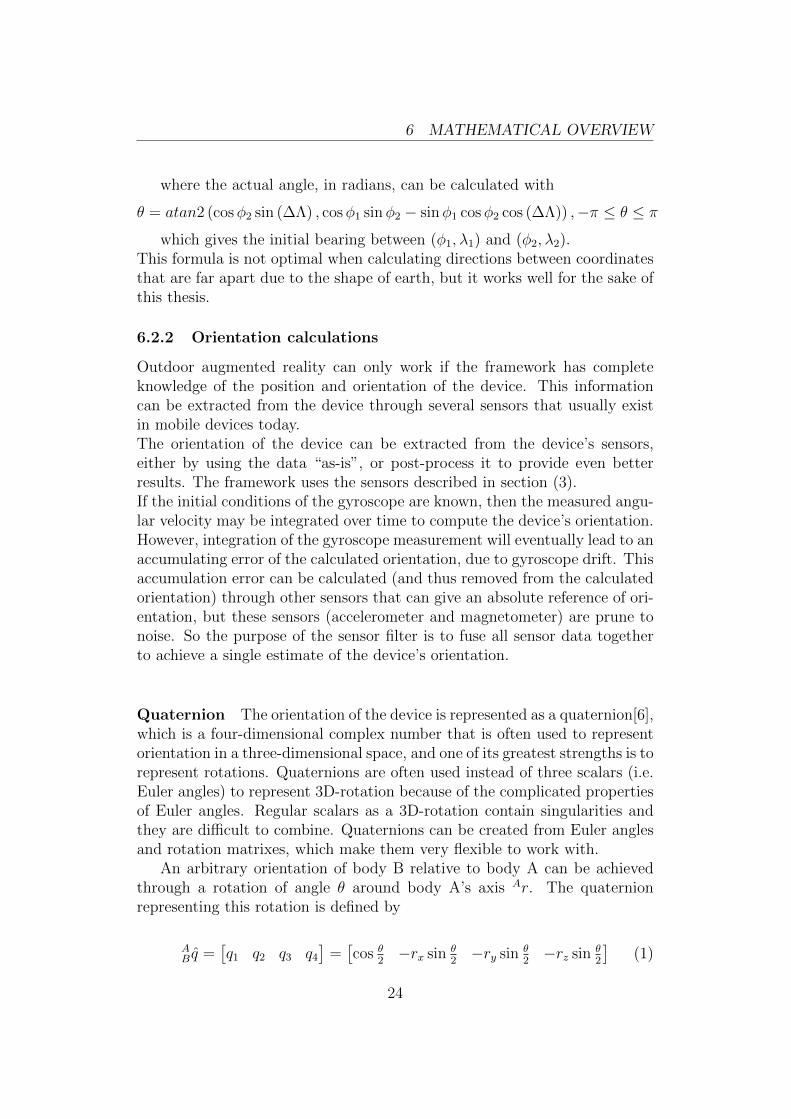
where the actual angle, in radians, can be calculated with
θ = atan2 (cosφ2 sin (∆Λ) , cosφ1 sinφ2 − sinφ1 cosφ2 cos (∆Λ)) ,−π ≤ θ ≤ π
which gives the initial bearing between (φ1, λ1) and (φ2, λ2).This formula is not optimal when calculating directions between coordinatesthat are far apart due to the shape of earth, but it works well for the sake ofthis thesis.
6.2.2 Orientation calculations
Outdoor augmented reality can only work if the framework has completeknowledge of the position and orientation of the device. This informationcan be extracted from the device through several sensors that usually existin mobile devices today.The orientation of the device can be extracted from the device’s sensors,either by using the data “as-is”, or post-process it to provide even betterresults. The framework uses the sensors described in section (3).If the initial conditions of the gyroscope are known, then the measured angu-lar velocity may be integrated over time to compute the device’s orientation.However, integration of the gyroscope measurement will eventually lead to anaccumulating error of the calculated orientation, due to gyroscope drift. Thisaccumulation error can be calculated (and thus removed from the calculatedorientation) through other sensors that can give an absolute reference of ori-entation, but these sensors (accelerometer and magnetometer) are prune tonoise. So the purpose of the sensor filter is to fuse all sensor data togetherto achieve a single estimate of the device’s orientation.
Quaternion The orientation of the device is represented as a quaternion[6],which is a four-dimensional complex number that is often used to representorientation in a three-dimensional space, and one of its greatest strengths is torepresent rotations. Quaternions are often used instead of three scalars (i.e.Euler angles) to represent 3D-rotation because of the complicated propertiesof Euler angles. Regular scalars as a 3D-rotation contain singularities andthey are difficult to combine. Quaternions can be created from Euler anglesand rotation matrixes, which make them very flexible to work with.
An arbitrary orientation of body B relative to body A can be achievedthrough a rotation of angle θ around body A’s axis Ar. The quaternionrepresenting this rotation is defined by
AB q =
[q1 q2 q3 q4
]=[cos θ
2−rx sin θ
2−ry sin θ
2−rz sin θ
2
](1)
24
6 MATHEMATICAL OVERVIEW
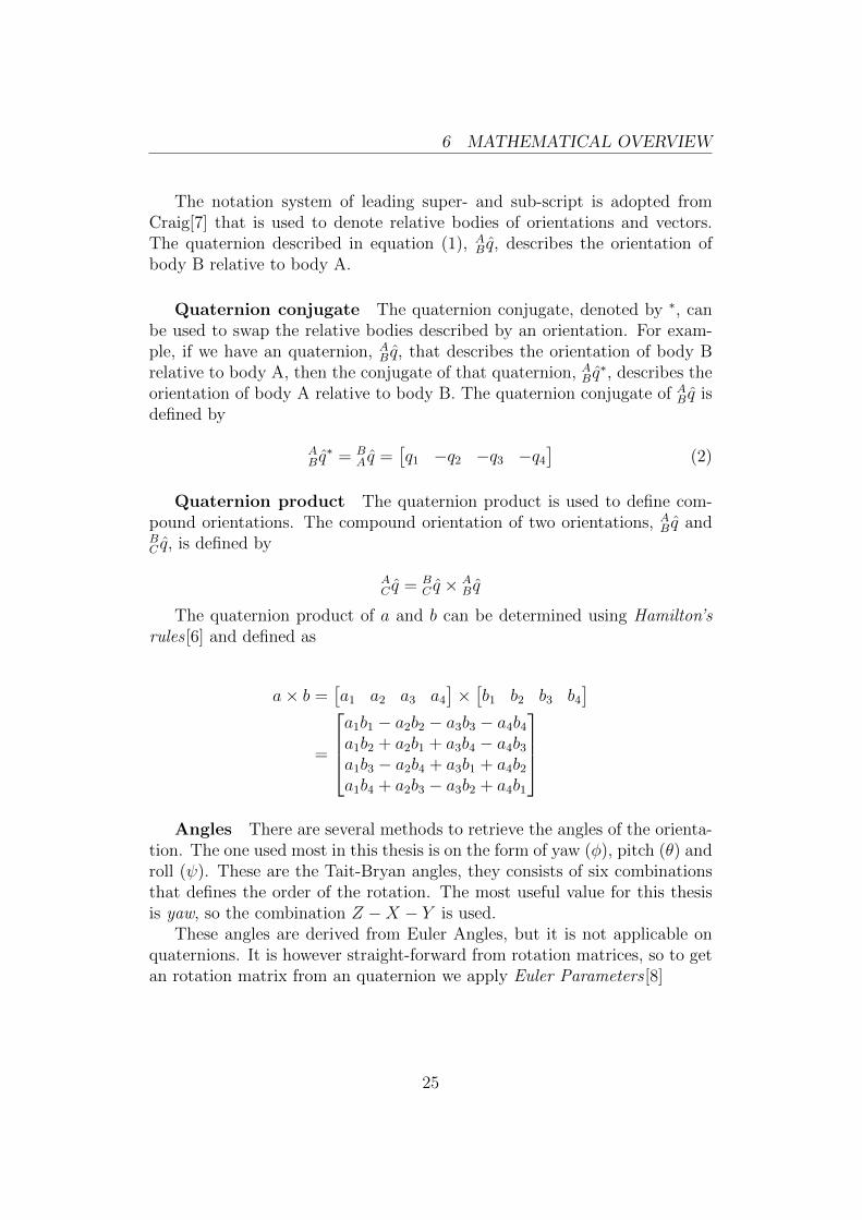
The notation system of leading super- and sub-script is adopted fromCraig[7] that is used to denote relative bodies of orientations and vectors.The quaternion described in equation (1), A
B q, describes the orientation ofbody B relative to body A.
Quaternion conjugate The quaternion conjugate, denoted by ∗, canbe used to swap the relative bodies described by an orientation. For exam-ple, if we have an quaternion, A
B q, that describes the orientation of body Brelative to body A, then the conjugate of that quaternion, AB q
∗, describes theorientation of body A relative to body B. The quaternion conjugate of AB q isdefined by
AB q∗ = B
A q =[q1 −q2 −q3 −q4
](2)
Quaternion product The quaternion product is used to define com-pound orientations. The compound orientation of two orientations, AB q andBC q, is defined by
AC q = B
C q × AB q
The quaternion product of a and b can be determined using Hamilton’srules [6] and defined as
a× b =[a1 a2 a3 a4
]×[b1 b2 b3 b4
]=
a1b1 − a2b2 − a3b3 − a4b4a1b2 + a2b1 + a3b4 − a4b3a1b3 − a2b4 + a3b1 + a4b2a1b4 + a2b3 − a3b2 + a4b1
Angles There are several methods to retrieve the angles of the orienta-
tion. The one used most in this thesis is on the form of yaw (φ), pitch (θ) androll (ψ). These are the Tait-Bryan angles, they consists of six combinationsthat defines the order of the rotation. The most useful value for this thesisis yaw, so the combination Z −X − Y is used.
These angles are derived from Euler Angles, but it is not applicable onquaternions. It is however straight-forward from rotation matrices, so to getan rotation matrix from an quaternion we apply Euler Parameters [8]
25
6 MATHEMATICAL OVERVIEW
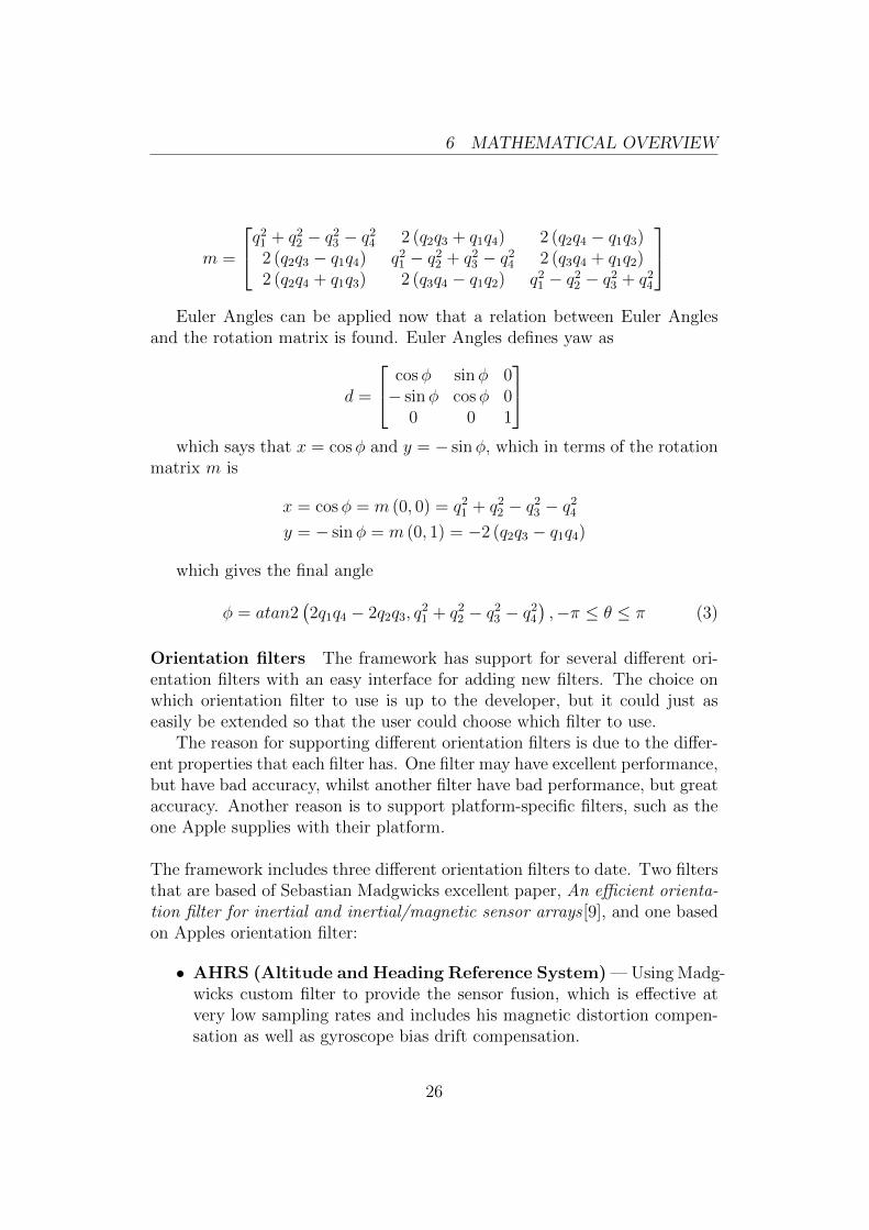
m =
q21 + q22 − q23 − q24 2 (q2q3 + q1q4) 2 (q2q4 − q1q3)2 (q2q3 − q1q4) q21 − q22 + q23 − q24 2 (q3q4 + q1q2)2 (q2q4 + q1q3) 2 (q3q4 − q1q2) q21 − q22 − q23 + q24
Euler Angles can be applied now that a relation between Euler Angles
and the rotation matrix is found. Euler Angles defines yaw as
d =
cosφ sinφ 0− sinφ cosφ 0
0 0 1
which says that x = cosφ and y = − sinφ, which in terms of the rotation
matrix m is
x = cosφ = m (0, 0) = q21 + q22 − q23 − q24y = − sinφ = m (0, 1) = −2 (q2q3 − q1q4)
which gives the final angle
φ = atan2(2q1q4 − 2q2q3, q
21 + q22 − q23 − q24
),−π ≤ θ ≤ π (3)
Orientation filters The framework has support for several different ori-entation filters with an easy interface for adding new filters. The choice onwhich orientation filter to use is up to the developer, but it could just aseasily be extended so that the user could choose which filter to use.
The reason for supporting different orientation filters is due to the differ-ent properties that each filter has. One filter may have excellent performance,but have bad accuracy, whilst another filter have bad performance, but greataccuracy. Another reason is to support platform-specific filters, such as theone Apple supplies with their platform.
The framework includes three different orientation filters to date. Two filtersthat are based of Sebastian Madgwicks excellent paper, An efficient orienta-tion filter for inertial and inertial/magnetic sensor arrays [9], and one basedon Apples orientation filter:
• AHRS (Altitude and Heading Reference System) — Using Madg-wicks custom filter to provide the sensor fusion, which is effective atvery low sampling rates and includes his magnetic distortion compen-sation as well as gyroscope bias drift compensation.
26

7 IMPLEMENTATION
• Alternative AHRS — Based on Mahony’s Direction-Cosine-Matrixfilter including Madgwicks magnetic distortion compensation.
• Apple — Uses an unknown algorithm to perform the filtering. Thisfilter does however require that the device is oriented towards south forthe orientation filter to get the correct initial bearing.
Currently the orientation filter from Apple is the recommended one sinceit has the least drift. The reason for this is that Apple has complete knowl-edge of the gyroscope’s drift and bias. The necessary method needed tocompute these values was outside the scope of this thesis. If time was givento add support for calculating these values then Madgwicks filter would prob-ably work very well.
7 Implementation
This section contains detailed information on how the prototype was im-plemented; including details on how each proposed interface uses the mathdescribed in the previous section.
The implementation of the framework was done over a 4-week period wherethe reference was the architectural sketches made earlier. During the courseof the development, several changes were made to the sketches to bettermatch the outcome of the framework, since these changes were necessary forthe framework to work.
7.1 Platforms
The initial implementation of the framework is mostly platform-independent.Currently Apple’s iOS is the only platform that is fully supported, and tosupport other platforms the following has to be implemented
7.1.1 Device
The device-component handles all platform-specific such as loading images,creating an appropriate video driver and so on.
7.1.2 Video driver
The video driver is responsible for implementing the rendering-pipeline, in-cluding matrix operations (i.e. object transforms) and creating textures.
27
7 IMPLEMENTATION
The three major mobile platforms to-date is Apples iOS, Google Androidand Windows Phone, and all these platforms are based on different technolo-gies, and thus different frameworks for rendering.
OpenGL ES The main video driver is based on OpenGL ES, which isa specialized version of OpenGL for Embedded Systems (ES). OpenGL isan industry standard API for developing high-performance 2D/3D graphicsapplications. OpenGL is quite popular, where part of its popularity comesfrom the fact that it is supported on many platforms (including all majorPC operating systems).
OpenGL was chosen as the main video driver due to several reasons
• Supported on Apples iOS and Google Android
• High-performance
• Easy to work with
Platform-specific All major platforms have their specialized frameworkfor drawing graphical elements, such as the user interface. These frameworkscan also be utilized by the developer to display custom interfaces, developinggames or something completely different. Though these frameworks usuallyonly provides functions for 2D rendering, which leaves the 3D-implementationto the developer.
Software If this framework is used on a platform that doesn’t provide anyrendering-frameworks to the developer, then there is always the option ofcreating an software-renderer, even though it would be a lot of work.
7.1.3 Sensors
The sensors available on a device is different between devices families andplatforms, but currently the following sensors are implemented and used
• Accelerometer
• Camera
• Compass
• GPS
• Gyroscope
28
7 IMPLEMENTATION
7.2 Libraries
The framework makes use of several libraries that provides well-tested func-tionality. These libraries are briefly described here.
7.2.1 libcurl
Network-access is handled with libcurl9, which is a open-source and easy-to-use client-side URL transfer library. It supports many protocols and is veryflexible, as well as being very portable. It is currently used for fetching mapsand directions, but this can of course be used as the developer wishes.
7.2.2 µSTL
Common classes such as lists, hash-maps, strings and so on is handled withµSTL10. µSTL is an open-source and platform independent replacement tothe C++ standard template library (STL). An alternative is used since STLis not supported on all platforms (Android for example).
7.2.3 tinyxml
XML-parsing is handled using tinyxml11. XML-parsing is currently only usedfor parsing directions, but it can of course be used by however the developerchooses.
7.3 Experimental implementation
The experimental part of this thesis was to try out different interfaces re-garding augmented reality. The interfaces and how they are implementedare covered below.
7.3.1 The map
The map is fetched using Google Static Maps API12. This allows for easyaccess of map-images, but it would be quite easy to change the source tosome other map-service.
9http://curl.haxx.se/libcurl/10http://ustl.sourceforge.net/11http://www.grinninglizard.com/tinyxml/12http://code.google.com/apis/maps/documentation/staticmaps/
29
7 IMPLEMENTATION
Positions Positions are used to indicate where in the users surroundingpoints of interests are located. These positions are naıvely estimated basedon the distance and direction from the user, which is neither fast nor accurate.This method is used since the knowledge of the map coverage is unknown,but it works as supposed for the sake of the prototype.
7.3.2 Perspective map
The main goal of the perspective map was to make an interface that is ahybrid between 2D and 3D, so the interface can transform itself dependingon how the user wants it. This of course does not only apply to a map, butadding a map on top of the interface makes it easy and clear to interact with.
It is called perspective map since the interface knows the orientation of thedevice and reacts to changes in the orientation. The sensor fusion algorithmgives the framework an absolute orientation, which tells the yaw, roll andpitch of the device, but in the form of a quaternion. What the frameworkgets is an quaternion that is the orientation of body D (the device) relativeto body E (earth), or in the notation used earlier, EDq. Using this quaternionon the device is not very interesting since the device itself already has thesame orientation the quaternion is representing.
But by using equation (2) on EDq would instead transform the quaternion
that represents the orientation of body E (earth) relative to body D (thedevice). This means the ground orientation relative to the device, which isexactly what the interface is using. So if the device is parallel to the groundthen the interface will show a 2D-interface, but the interface stays parallelto the ground as the device is tilted, which shows the 3D-interface.
7.3.3 Height-map
The height-map is similar to the perspective map; it shares the same 2D/3D-interface as well as the map. However, the big difference is that this interfaceshows a supposed height-map of the users immediate surrounding.
7.3.4 Radar
The radar also builds on the map, but it is always shown in 2D in this mode.The whole interface is rotated due north since it is supposed to simulate a”radar”. By applying equation (3) on E
Dq∗ return the heading due north. The
dots drawn on the interface indicates points of interest that is close to theuser. The position of these dots is calculated based on the distance from theuser and the direction between the point and direction the device is pointing.
30
8 FUTURE WORK
7.3.5 Directions
The directions are fetched using Google Directions API. Their API requires atleast two coordinates, starting coordinate and destination coordinate, alongwith a couple of other insignificant parameters. The service returns theshortest route when asking for directions; this route consists of one or moresteps, where each step contains a single instruction that includes distanceand duration. Each step also includes a encoded polyline13 which defines thepath the current step consists of. The encoding consists of base64 14 encodingon the signed latitude and longitude values, and to further preserve space,points only include the offset from the previous point (except the first point).
Each point is also mapped to the internal coordinate system so it isrendered with the right size and scale. This step is very important sinceeach point is unknown to each other, they instead relies on the path suppliedby Google, so that the points connect given a universal coordinate system.
The directions are ready when these steps have been parsed; where eachstep becomes a point of interest so automatic filtering is performed. Eachstep is rendered as a 3D-arrow pointing in the direction that the user shouldtravel.
8 Future work
The framework is fully functional, but it has some unnecessary complex partsthat should be changed. There are also some other parts of the frameworkthat aren’t optimal due to time constraints and the typical properties of aprototype.
Some changes that should be made to make the framework complete:
• The framework uses the scene-graph principle, but does not implementit fully, so transforms have to be inherited from parents to childrenmanually even though it should be handled automatically.
• Functions for initializing/calibrating custom sensor fusion algorithms.
• Compensate for initial calibration errors.
• Redesign the AR module to better match the framework.
• Change text-renderer to bitmaps instead of platform-specific to getbetter performance.
13http://code.google.com/apis/maps/documentation/utilities/polylinealgorithm.html14http://www.faqs.org/rfcs/rfc3548.html
31
8 FUTURE WORK
• Expanding each interface to include more information. Directions couldfor instance include distances, road names and so on.
8.1 Filtering
There is always room for improvement when working with sensors, and thisis true for this framework as well. Functions for calibrating the sensor fu-sion algorithm should be added because without those custom sensor fusionalgorithms will have unsatisfactory result due to unwanted drift and so on.Initial compensation for sensor fusion should also be added since sensor fu-sion algorithms are normally calibrated due to the direction of the device atinitialization.
Another sensor that can be filtered is the GPS. Using GPS-filtering wouldimprove the calculated position by disregarding position-updates based onother sensor-values. So, the gyroscope and accelerometer could for examplebe used to make an estimate on how much the user has moved since the lastposition update and then make a decision whether or not the new value isconsidered valid.
8.2 Functionality
One of the major changes to the framework would be the incorporation of amarker-less tracking module. It would require a considerate amount of timeto optimize a marker-less tracker to work satisfactory on mobile devices, butit would open up for some very interesting adaptations of the framework. Amarker-less tracker would allow the framework to add interactive objects toalmost anything, enabling full outdoor/indoor augmentation.
The need for optimization is quite big when developing mobile applications,and it is even more so if the framework would be expanded with supportfor marker-less tracking. There are quite a few tricks for optimizing appli-cations on mobile devices. Considering that this framework is very CPUintensive, it would make a lot of sense to add optimization in that area,specifically with mathematical intensive algorithms. These areas would getdramatic speed improvements if the dedicated math-unit found in most oftoday’s mobile processors would be utilized. Marker-less trackers is basedon image-processing, which is very CPU intensive, so that part would getdramatic speed improvements by utilizing the GPU.
32
9 CONCLUSION
9 Conclusion
The final result of the framework is pretty stable and most important very funto work with. Using the framework takes the uncharted territory of mobileaugmented reality interfaces to a familiar setting and makes the designingprocess a breeze compared to drawing the interfaces.
The author strongly believes that the result is proof that the developmentof interactive interfaces should be done using prototyping. The complexity indefining evolving interfaces on paper is much higher than actually implement-ing them using this framework. All interfaces implemented have been testedin various situations and behaves according to the initial expectations of theinterfaces. These interfaces could not be verified on paper so the author isvery satisfied with the result now that they live up to the expectations.
33
LIST OF FIGURES
List of Figures
1 Perspective map example with some points of interest and theuser position. . . . . . . . . . . . . . . . . . . . . . . . . . . . 13
2 This height-map is a static model, but it gives a good estimateon how it would look given real data. . . . . . . . . . . . . . . 14
3 The radar resides in the upper-right corner, where the usercan see points of interest relative to their location. . . . . . . . 15
4 The directions are just as any other object in the 3D-world,but they build the path the user should follow to get to thedestination. . . . . . . . . . . . . . . . . . . . . . . . . . . . . 16
5 UML-layout of the Core-module. . . . . . . . . . . . . . . . . 196 UML-layout of the Graphics-module. . . . . . . . . . . . . . . 207 UML-layout of the Sensors-module. . . . . . . . . . . . . . . . 208 UML-layout of the AR-module. . . . . . . . . . . . . . . . . . 21
34
REFERENCES
References
[1] M. L. Heilig, Sensorama Simulator , 1961.
[2] D. Wagner, A. Mulloni, T. Langlotz, D. Schmalstieg, Real-timePanoramic Mapping and Tracking on Mobile Phones , 2010.
[3] G. Klein, D. Murray, Parallel Tracking and Mapping for Small ARWorkspaces , 2007.
[4] The Math Forum @ Drexel (http://mathforum.org/), Derivation of theHaversine formula, 1999.
[5] The Math Forum @ Drexel http://mathforum.org/, Bearing between twopoints , 2002.
[6] Weisstein, Eric W. ”Quaternion.” From MathWorld – A Wolfram WebResource. http://mathworld.wolfram.com/Quaternion.html.
[7] John J. Craig, Introduction to Robotics Mechanics and Control, PearsonEducation International, 2005.
[8] Weisstein, Eric W. ”Euler Parameters.” From MathWorld – A WolframWeb Resource. http://mathworld.wolfram.com/EulerParameters.html.
[9] Sebastian O.H. Madgwick, An efficient orientation filter for inertial andinertial/magnetic sensor arrays , 2010.
35
A PROTOTYPE
Appendices
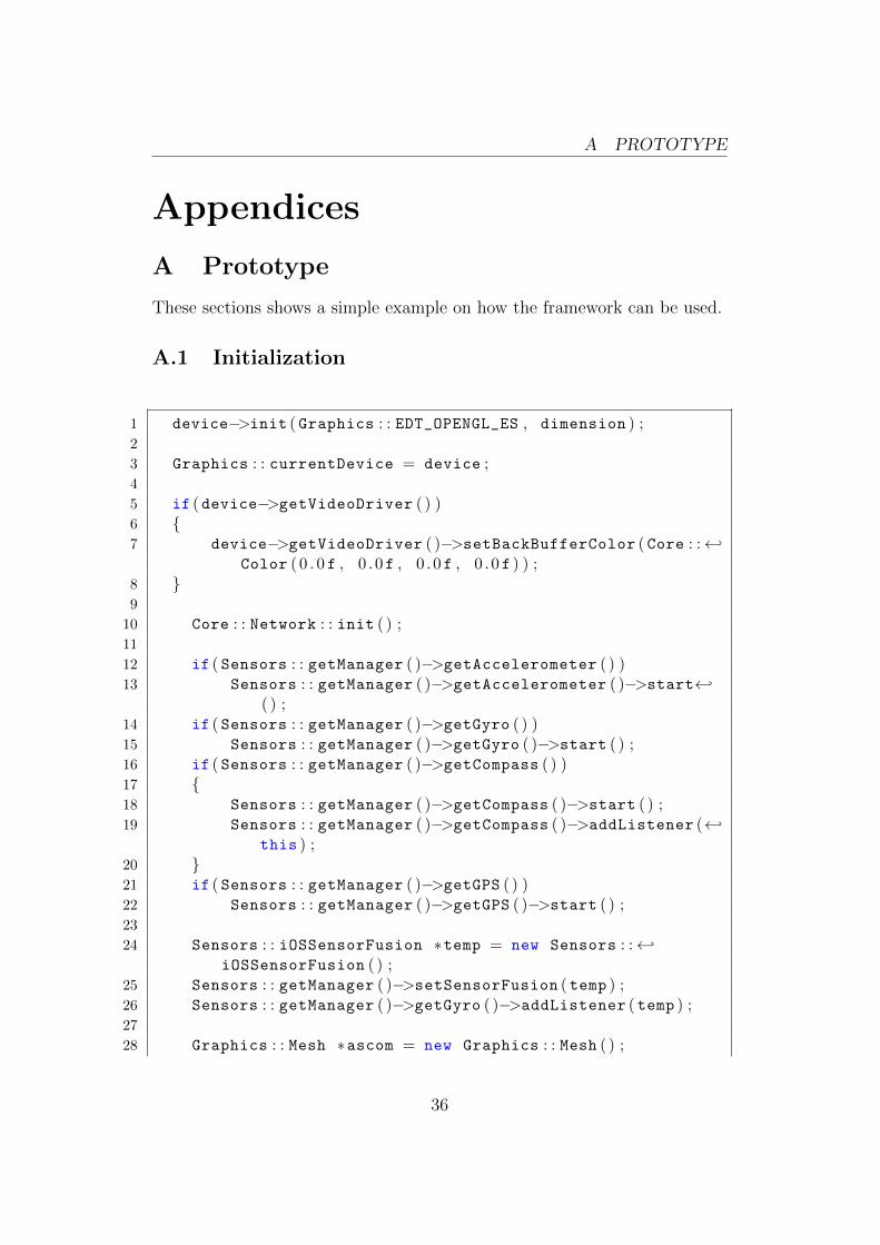
A Prototype
These sections shows a simple example on how the framework can be used.
A.1 Initialization
1 device−>init ( Graphics : : EDT_OPENGL_ES , dimension ) ;2
3 Graphics : : currentDevice = device ;4
5 if ( device−>getVideoDriver ( ) )6 {7 device−>getVideoDriver ( )−>setBackBufferColor ( Core : :←↩
Color ( 0 . 0 f , 0 . 0f , 0 . 0f , 0 . 0 f ) ) ;8 }9
10 Core : : Network : : init ( ) ;11
12 if ( Sensors : : getManager ( )−>getAccelerometer ( ) )13 Sensors : : getManager ( )−>getAccelerometer ( )−>start←↩
( ) ;14 if ( Sensors : : getManager ( )−>getGyro ( ) )15 Sensors : : getManager ( )−>getGyro ( )−>start ( ) ;16 if ( Sensors : : getManager ( )−>getCompass ( ) )17 {18 Sensors : : getManager ( )−>getCompass ( )−>start ( ) ;19 Sensors : : getManager ( )−>getCompass ( )−>addListener (←↩
this ) ;20 }21 if ( Sensors : : getManager ( )−>getGPS ( ) )22 Sensors : : getManager ( )−>getGPS ( )−>start ( ) ;23
24 Sensors : : iOSSensorFusion ∗temp = new Sensors : :←↩iOSSensorFusion ( ) ;
25 Sensors : : getManager ( )−>setSensorFusion ( temp ) ;26 Sensors : : getManager ( )−>getGyro ( )−>addListener ( temp ) ;27
28 Graphics : : Mesh ∗ascom = new Graphics : : Mesh ( ) ;
36

A PROTOTYPE
29 ascom−>loadT2N3V3(&ascom_vertex [ 0 ] [ 0 ] , ←↩ascom_vertexcount , &ascom_index [ 0 ] [ 0 ] , ←↩ascom_polygoncount ) ;
30
31 Graphics : : MeshManager : : instance ( )−>addMesh ( ascom , "←↩ascom" ) ;
32
33 ustl : : vector<AR : : Point∗> ar ;34 AR : : Point ∗point ;35
36 point = new AR : : TemplatePoint<AscomNode>(Core : :←↩Coordinate (64 .6991146124539f , 21.188764572143555f )←↩) ;
37 point−>setName ("Ascom/Huvud" ) ;38 ar . push_back ( point ) ;39
40 point = new AR : : TemplatePoint<AscomNode>(Core : :←↩Coordinate (64.70030673882691f , 21.18691921234131f )←↩) ;
41 point−>setName ("Ascom/Lotsen" ) ;42 ar . push_back ( point ) ;43
44 Graphics : : SceneManager ∗mgr = device−>getSceneManager←↩( ) ;
45 AR : : ARManager : : instance ( )−>setSceneManager ( mgr ) ;46
47 AR : : PerspectiveMapNode ∗p = new AR : :←↩PerspectiveMapNode (NULL , mgr ) ;
48 mgr−>addSceneNode (p ) ;49 p−>release ( ) ;50 AR : : ARManager : : instance ( )−>addListener (p ) ;51
52 AR : : DirectionsNode ∗n = new AR : : DirectionsNode (NULL , ←↩mgr ) ;
53 n−>fetchDirections ( Core : : Coordinate (64 .751143f←↩, 20 . 974789 f ) , Core : : Coordinate (64 .7570370474089f , ←↩20.971097946166992f ) ) ;
54 mgr−>addSceneNode (n ) ;55 n−>release ( ) ;56
57 AR : : RadarNode ∗r = new AR : : RadarNode (NULL , mgr , 20 .0 f←↩) ;
58 mgr−>addSceneNode (r ) ;
37
A PROTOTYPE
59 r−>release ( ) ;60
61 AR : : ARManager : : instance ( )−>addPoints (ar ) ;62
63 if ( Graphics : : getCurrentMap ( ) != NULL )64 Graphics : : getCurrentMap ( )−>addListener (AR : :←↩
ARManager : : instance ( ) ) ;65
66 for ( size_t i = 0 ; i < ar . size ( ) ; i++)67 {68 point = ar [ i ] ;69 point−>release ( ) ;70 }71
72 Graphics : : VideoDriver ∗driver = device−>←↩getVideoDriver ( ) ;
73 driver−>addListener (AR : : ARManager : : instance ( ) ) ;74 driver−>setOrtho ( Core : : Vector2f ( 0 . 0 f , 100 .0 f / driver←↩
−>getAspectRatio ( ) ) , Core : : Vector2f (100 . 0 f , 0 . 0 f ) ,←↩−1.0f , 1 . 0 f ) ;
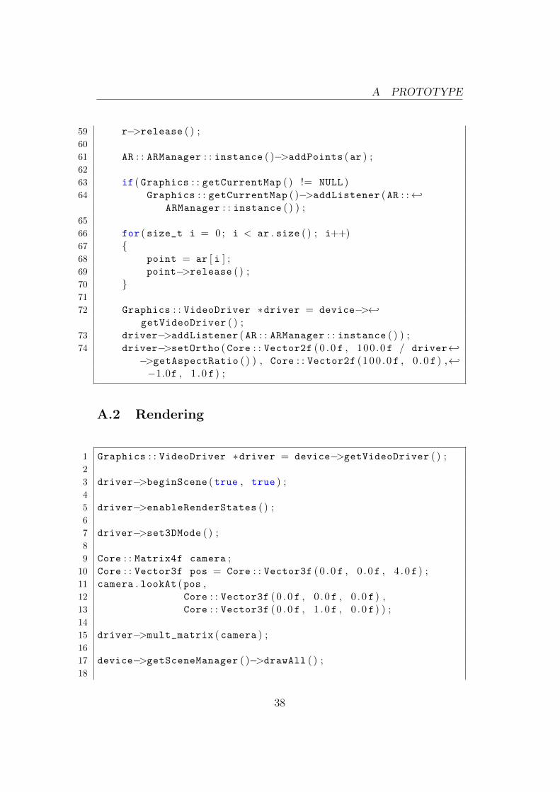
A.2 Rendering
1 Graphics : : VideoDriver ∗driver = device−>getVideoDriver ( ) ;2
3 driver−>beginScene (true , true ) ;4
5 driver−>enableRenderStates ( ) ;6
7 driver−>set3DMode ( ) ;8
9 Core : : Matrix4f camera ;10 Core : : Vector3f pos = Core : : Vector3f ( 0 . 0 f , 0 . 0f , 4 . 0 f ) ;11 camera . lookAt (pos ,12 Core : : Vector3f ( 0 . 0 f , 0 . 0f , 0 . 0 f ) ,13 Core : : Vector3f ( 0 . 0 f , 1 . 0f , 0 . 0 f ) ) ;14
15 driver−>mult_matrix ( camera ) ;16
17 device−>getSceneManager ( )−>drawAll ( ) ;18
38

A PROTOTYPE
19 driver−>disableRenderStates ( ) ;20
21 driver−>endScene ( ) ;
39