audio coding - mcmaster universityshirani/multi12/audiocompression.pdf · • mpeg audio coding has...
TRANSCRIPT
Multimedia Communications
Audio coding
Copyright S. Shirani
Introduction • Lossy compression schemes can be based on source model
(e.g., speech compression) or user model (audio coding) • Unlike speech, audio signals can be generated by different
mechanisms • Lacking a unique model for audio production, audio
compression methods have focused on the unique model for audio perception (psychoacoustic model of human perception)
• By identifying what can and cannot be heard, audio compression schemes obtain their compression by discarding information that cannot be perceived
Copyright S. Shirani
Introduction • Over the course of our evolutionary history, we have
developed limitations on what we can hear • These limitations are physiological (based on machinery of
hearing) or psychological (based on how our brain processes auditory stimuli)
• The machinery of hearing is frequency dependent • Variation of what is perceived as equally loud at different
frequencies is usually displayed as a set of equal loudness curves
• In these curves the sound pressure level (SPL) is plotted as a function of frequency for tones perceived to be equally loud.

Copyright S. Shirani
Introduction • The SPL curve that delineates the boundary of audible and
inaudible sounds at different frequencies is threshold-of-hearing curve
Copyright S. Shirani
Introduction • Quantization (in lossy compression) can be modeled as an
additive noise • To hide quantization noise, we can make use of the fact that
signals below a particular amplitude at a particular frequency are not audible.
• If we select the quantization step size such that the quantization noise lies below the audibility threshold, the noise will not be perceived.
Copyright S. Shirani
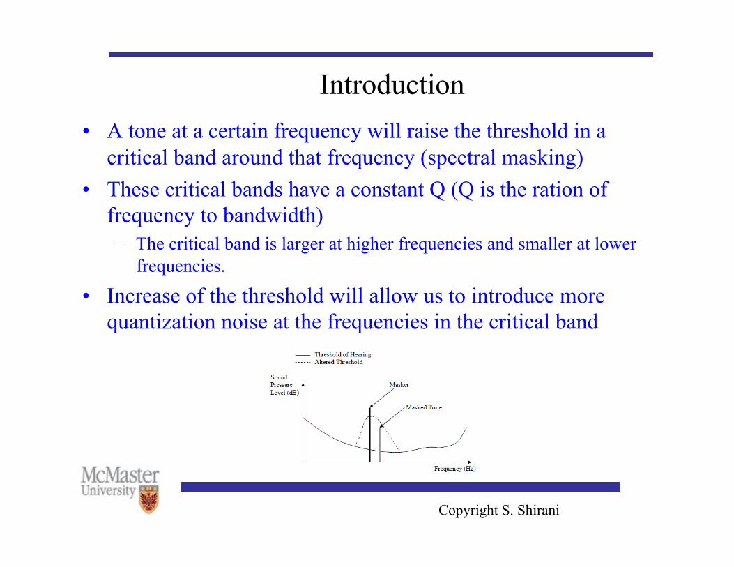
Introduction • A tone at a certain frequency will raise the threshold in a
critical band around that frequency (spectral masking) • These critical bands have a constant Q (Q is the ration of
frequency to bandwidth) – The critical band is larger at higher frequencies and smaller at lower
frequencies.
• Increase of the threshold will allow us to introduce more quantization noise at the frequencies in the critical band
Copyright S. Shirani
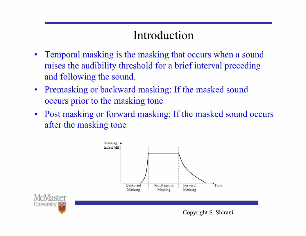
Introduction • Temporal masking is the masking that occurs when a sound
raises the audibility threshold for a brief interval preceding and following the sound.
• Premasking or backward masking: If the masked sound occurs prior to the masking tone
• Post masking or forward masking: If the masked sound occurs after the masking tone
Copyright S. Shirani
Introduction • A psychoacoustic model is used in MPEG audio coding • The first step in psychoacoustic model is to obtain a spectral
profile of the signal being encoded • The audio signal is windowed and transformed using filter
banks or a frequency domain transform • The SPL is calculated for each spectral band
Copyright S. Shirani
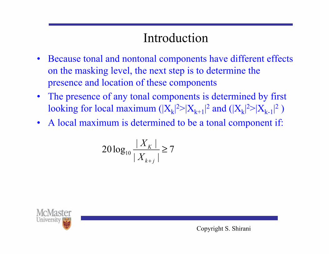
Introduction • Because tonal and nontonal components have different effects
on the masking level, the next step is to determine the presence and location of these components
• The presence of any tonal components is determined by first looking for local maximum (|Xk|2>|Xk+1|2 and (|Xk|2>|Xk-1|2 )
• A local maximum is determined to be a tonal component if:
Copyright S. Shirani
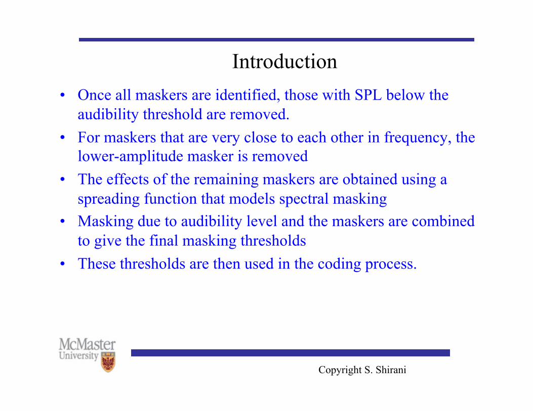
Introduction • Once all maskers are identified, those with SPL below the
audibility threshold are removed. • For maskers that are very close to each other in frequency, the
lower-amplitude masker is removed • The effects of the remaining maskers are obtained using a
spreading function that models spectral masking • Masking due to audibility level and the maskers are combined
to give the final masking thresholds • These thresholds are then used in the coding process.
Copyright S. Shirani
MPEG Audio Coding • Most standards have normative and informative sections • Normative: are required for compliance to standard • Most standards define the bitstream that should be presented
to the decoder, leaving the design of the encoder to individual vendors
• MPEG audio coding has three strategies known as Layer I, Layer II and Layer III.
• Each layer is progressively more complicated than the previous layer and provides higher compression
• The three layers are backward compatible.
Copyright S. Shirani
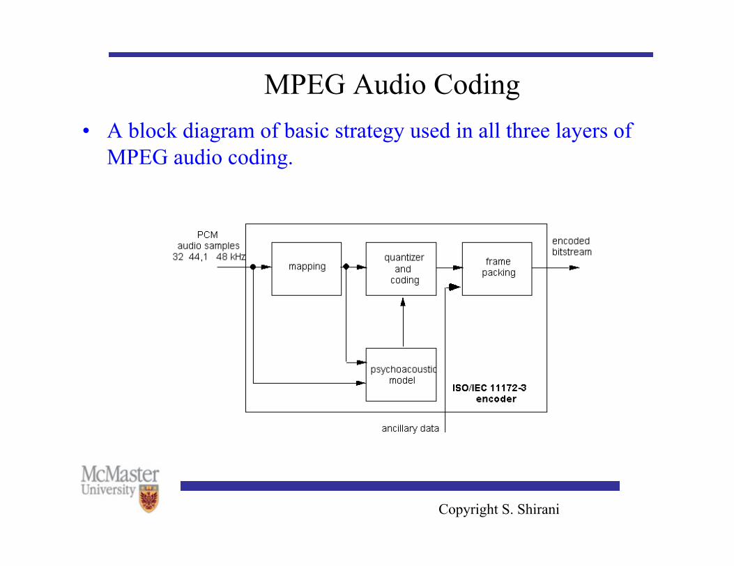
MPEG Audio Coding • A block diagram of basic strategy used in all three layers of
MPEG audio coding.
Copyright S. Shirani
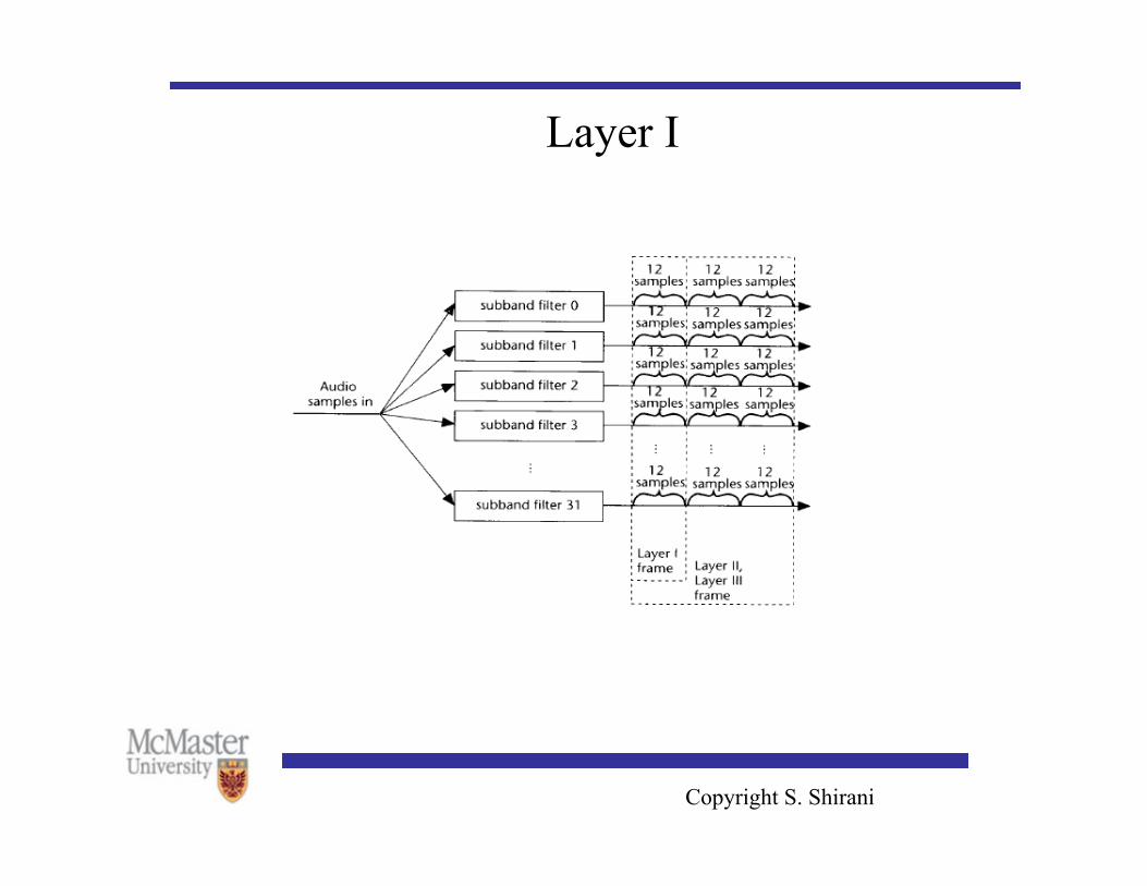
Layer I • In layer I coding the time frequency mapping is accomplished
using a bank of 32 subband filters • The output of each filter is down sampled by 32 • The samples are divided into groups of 12 samples each • Each group of 12 samples is examined to determine a
scalefactor. • The scalefactor is used to make sure that the coefficients
make use of the entire range of quantizer • The subband output is divided by the scalefactor before being
quantized
Copyright S. Shirani
Layer I • To determine the number of bits to be used for quantization of
each subband, the coder makes use of the psychoacoustic model
• Input to the model includes FFT of the audio data as well as the signal itself
• The model calculates the masking threshold in each subband and hence the quantization step size
• In layer I the encoder has a choice of 14 different quantizers for each band
• Quantizers are all midtread ranging from 3 levels to 65,535 levels
• 12 quantized samples from each subband (a total of 384), make up one frame
Copyright S. Shirani
Layer I
Copyright S. Shirani
Layer I • Total number of bits available to represent all the subbands is
fixed. • Bit allocation can be an iterative process with the objective of
keeping noise-to-mask ratio more or less constant across subbands
• Modes available in Layer I: stereo, joint stereo, dual channel, single channel – Stereo mode: two channels that are encoded separately but should be
played together – Joint stereo: left and right channels are combined to form mid and side
signals. – Dual channel mode consists of two channels that are encoded
separately and are not intended to be played together (e.g., translations)
Copyright S. Shirani
Layer II coding • Layer II coder groups three sets of 12 samples from each
subband into a frame – Total number of samples per frame increases from 384 samples to
1152 samples, which reduces the overhead
• In Layer II coding the encoder tries to share a scale factor among two or all three groups of samples from each subband.
• Major difference between Layer I and II coding schemes is in the quantization step.
• In Layer I each subband is quantized using one of 14 possibilities which are the same possibilities for each subband.
Copyright S. Shirani
Layer II coding • In Layer II, quantizer used for each subband can be selected
from a different set of quantizers depending on the sampling rate and bit rate
• For some sampling rate and bit rate combination many of higher subbands are assigned 0 bits.
Copyright S. Shirani
Layer III (mp3) • One of the problems with Layer I coding scheme was that with 32-band
decomposition, the bandwidth of the subband at lower frequencies is significantly larger than the critical band.
• This makes it difficult to make an accurate judgment of the mask-to-signal ratio. – If we get a high amplitude tone in a subband and if the subband is narrow, we
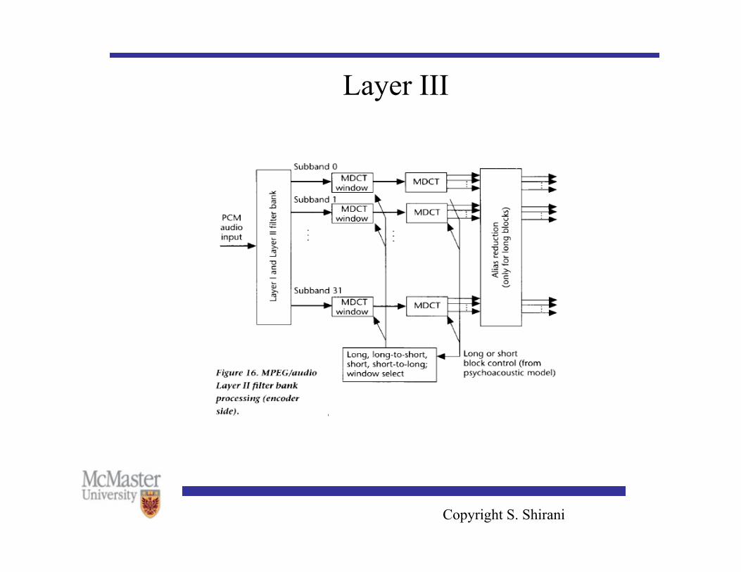
could assume that it will mask other tones in the subband • To satisfy backward compatibility requirement, the spectral decomposition
in Layer III algorithm is performed in two stages: a 32 band subband decomposition followed by a modified DCT (MDCT).
• MDCT can have two sizes 6 or 18 with 50% overlap. • Using different window sizes help prevent the spread of quantization noise
Copyright S. Shirani
Layer III (mp3) • Coding and quantization of output of MDCT is conducted in
an iterative fashion using two nested loops • Outer loop is called distortion control loop whose purpose is
to ensure that the introduced quantization noise is below the audibility threshold
• Inner loop is called the rate control loop and makes sure that the target bit rate is not exceeded.
• Typical compression ratio: 10:1
Copyright S. Shirani
Layer III
Copyright S. Shirani
Advanced Audio Coding (AAC) • The Advanced Audio Coding (AAC) standard was approved
as a higher quality multichannel alternative to backward compatible MPEG Layer III in 1997.
• AAC is modular and based on a set of modules (tools). • By using some or all these tools, the standard describes three
profiles: main, low complexity and sampling-rate-scalable
Copyright S. Shirani
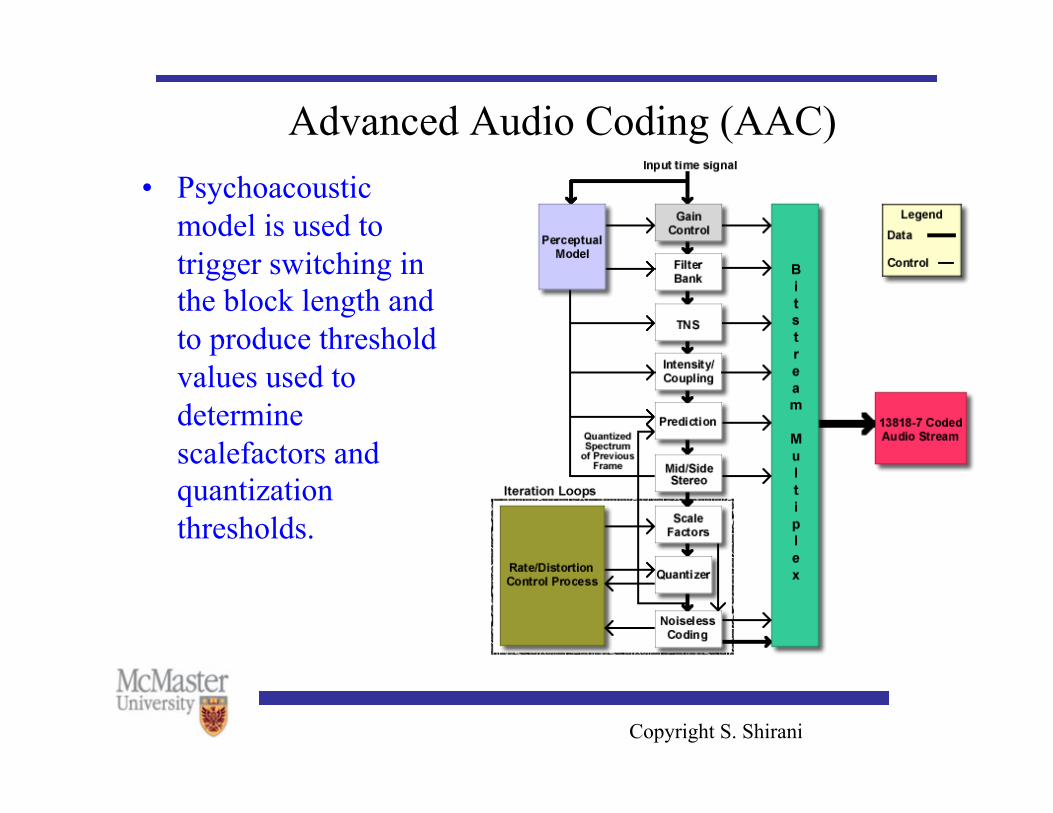
Advanced Audio Coding (AAC) • Psychoacoustic
model is used to trigger switching in the block length and to produce threshold values used to determine scalefactors and quantization thresholds.
Copyright S. Shirani
Advanced Audio Coding (AAC) • In AAC frequency decomposition is accomplished by a
MDCT. • AAC allows switching between a window length of 2048 and
256 samples (window lengths include 50% overlap with neighboring blocks).
• Longer block length allows the algorithm to take advantage of stationary portions of the input to get significant improvements in compression
• Short blocks allow the algorithm to handle sharp attacks without incurring substantial distortion and rate penalties.
Copyright S. Shirani
Advanced Audio Coding (AAC) • ACC algorithm uses prediction to reduce dynamic range of
the coefficients and further reduces the bit rate • ACC contains two kinds of predictors: intrablock (referred to
as Temporal Noise Shaping (TNS)) and interblock • Interblock predictor is used during stationary periods • During these periods it is reasonable to assume that the
coefficients at a certain frequency do not change their value significantly from block to block.
• When the audio input contains transient, AAC uses intraband predictor
• AAC uses neighboring coefficients to perform prediction.
Copyright S. Shirani
Advanced Audio Coding (AAC) • Quantization and coding strategy used in AAC:
– scale factors are used to control the quantization noise as a part of an outer distortion control loop
– Quantization step size is adjusted to accommodate a target bit rate in an inner rate control loop
• Stereo: AAC allows independent coding, Mid/Side coding and intensity stereo coding
Copyright S. Shirani
MPEG-4 AAC • MPEG-4 AAC: adds a perceptual noise substitution (PNS)
tool, a long term prediction (LTP), Transform Domain Weighted Interleave Vector Quantization (TwinVQ) and Bit Sliced Arithmetic Coding (BSAC)
Copyright S. Shirani
Dolby Digital (Dolby AC3) • Dolby AC3 has multichannel capability required by the movie
industry along with the ability to downmix the channels • The 5.1 channels include: right, center, left, left rear, and right
rear and a narrowband low frequency effect channel (0.1 channel)
• Dolby AC3 is now the standard used for DVD and Direct Broadcast Satellites
• As MPEG, Dolby AC3 uses modified DCT with 50% overlap for frequency decompostion
• As MPEG there are two different sizes of windows used: for stationary portions of audio size is 512 and for non-stationary parts 256
Copyright S. Shirani
Dolby Digital (Dolby AC3) • In MPEG schemes the audio sequence being encoded is
provided to the bit allocation procedure and the bit allocation is sent to the decoder as side information
• In Dolby AC3 scheme the signal itself is not provided to the bit allocation. Instead a crude representation of the spectral envelop is provided to both the decoder and the bit allocation procedure.
• Since decoder has the information used to generate the bit allocation, the allocation itself is not included in the transmitted bitstream.