atsc standard: atsc data application reference model...atsc atsc data application reference model 16...
TRANSCRIPT
Doc. A/94 16 August 2002
ATSC Standard:
ATSC Data Application Reference Model
Advanced Television Systems Committee 1750 K Street, N.W.
Suite 1200
Washington, D.C. 20006
www.atsc.org
ATSC ATSC Data Application Reference Model 16 August 2002
2
The Advanced Television Systems Committee, Inc., is an international, non-profit organization developing voluntary standards for digital television. The ATSC member organizations represent the broadcast, broadcast equipment, motion picture, consumer electronics, computer, cable, satellite, and semiconductor industries.
Specifically, ATSC is working to coordinate television standards among different communications media focusing on digital television, interactive systems, and broadband multimedia communications. ATSC is also developing digital television implementation strategies and presenting educational seminars on the ATSC standards.
ATSC was formed in 1982 by the member organizations of the Joint Council on InterSociety Coordination (JCIC): the Electronic Industries Association (EIA), the Institute of Electrical and Electronic Engineers (IEEE), the National Association of Broadcasters (NAB), the National Cable Television Association (NCTA), and the Society of Motion Picture and Television Engineers (SMPTE). Currently, there are approximately 160 members representing the broadcast, broadcast equipment, motion picture, consumer electronics, computer, cable, satellite, and semiconductor industries.
ATSC Digital TV Standards include digital high definition television (HDTV), standard definition television (SDTV), data broadcasting, multichannel surround-sound audio, and satellite direct-to-home broadcasting.
ATSC ATSC Data Application Reference Model 16 August 2002
3
Table of Contents
1. SCOPE........................................................................................................................................................7 1.1 Status 7 1.2 Purpose 7 1.3 Application 7 1.4 Organization 7
2. REFERENCES............................................................................................................................................8 2.1 Normative References 8 2.2 Informative References 9 2.3 Reference Acquisition 9
3. DEFINITIONS AND STRUCTURES ...........................................................................................................9 3.1 Conformance Keywords 10 3.2 Acronyms and Abbreviations 10 3.3 Terms 11 3.4 Section and Data Structure Syntax Notation 13 3.5 Special Field Meanings 13
4. SYSTEM ASSUMPTIONS (INFORMATIVE) ............................................................................................13
5. OVERVIEW (INFORMATIVE)...................................................................................................................14 5.1 Data Models 14 5.2 Application Model 14
5.2.1 Application Categories 14 5.2.2 Application Announcement 15 5.2.3 Application Signaling 15 5.2.4 Resource Signaling 16
5.3 Security and Policy 16
6. APPLICATION STATE MODEL ...............................................................................................................16 6.1 Background on SDF and PSI Facilities (Informative) 16 6.2 Events 17 6.3 States 18 6.4 State Transitions 18 6.5 State Transition Diagram 19
7. IDENTIFICATION AND NAMING .............................................................................................................19 7.1 The tv: Scheme 20 7.2 The lid: Scheme 20 7.3 Content Types and Their URI Dependent Behavior 21
ATSC ATSC Data Application Reference Model 16 August 2002
4
8. DATA ENCAPSULATION ........................................................................................................................22 8.1 IP Packets 22 8.2 Modules 22 8.3 Files 23 8.4 Streams 23
8.4.1 MPEG-2 Video Picture UserData (DTVCC) 23 8.5 Triggers 23
8.5.1 Asynchronous Events 23 9. DESCRIPTORS AND STRUCTURES ......................................................................................................23
9.1 Compatibility Wrapper Descriptor 24 9.2 DSM-CC Compatibility Descriptor 24 9.3 Broadcaster Policy Descriptor 25 9.4 Service Name Descriptor 27 9.5 URI Descriptor 27 9.6 Summary of Descriptor Locations (Informative) 28
10. ANNOUNCEMENT .................................................................................................................................28 10.1 Application Announcement 29
11. SIGNALING............................................................................................................................................29 11.1 Virtual Channel Signaling 29 11.2 Application Signaling 29 11.3 Resource Signaling 30 11.4 Broadcaster Policy 31 11.5 External Resource Signaling (Informative) 31
12. APPLICATION BUFFER MODELS........................................................................................................31 12.1 DTVCC Buffer Model 32 12.2 Module Buffer Model 32
12.2.1 Data Module Buffers 32 12.2.2 Application Buffer Model 33
12.3 Stream Buffer Model 34 12.3.1 Data Piping 34 12.3.2 Asynchronous Download 35
Annex A: Use of the Signaling and Announcement Facilities (Informative) 36
Annex B: Receiver Tuning Operations (Informative) 37
Annex C: URI Resolution Procedures (Informative) 38
ATSC ATSC Data Application Reference Model 16 August 2002
5
Annex D: Application Environment (Informative) 39
1. APPLICATION ENVIRONMENT MODEL.................................................................................................39 1.1 Display Model 39 1.2 Audio Model 39 1.3 Viewer Input 39 1.4 Resource Acquisition 40
Annex E: Descriptors from Other Standards (Informative) 42
1. DSM-CC COMPATIBILITY DESCRIPTOR...............................................................................................42 1.1 Content Type Descriptor 42 1.2 Acquisition Descriptor 43
ATSC ATSC Data Application Reference Model 16 August 2002
6
Index of Tables and Figures
Table 6.1 State Transition Summary 19 Table 7.1 Video/Audio Query Syntax and Their Resulting Content Types. 22 Table 9.1 Compatibility Wrapper Descriptor 24 Table 9.2 Broadcaster Policy Descriptor 25 Table 9.3 Policy and Bitfield Assignment 26 Table 9.4 Service Name Descriptor 27 Table 9.5 URI Descriptor 28 Table 9.6 Descriptor Location Summary 28 Table 11.1 Protocol Encapsulations 30 Table 12.1 Buffer Model Notations. 34 Table E.1 DSM-CC Compatibility Descriptor 42 Table E.2 Content Type Descriptor 42 Table E.3 Acquisition Descriptor 43
Figure 4.1 Relationship among ATSC Standards. 13 Figure 6.1 State transition diagram. 19 Figure 12.1 DSM-CC Module Buffer Model. 34 Figure A.1 SDF linkage. 36 Figure D.1 Receiver reference model data flow. 40
ATSC ATSC Data Application Reference Model 16 August 2002
7
ATSC Data Application Reference Model
1. SCOPE
1.1 Status
This document is an ATSC Standard, having passed ATSC Member Ballot on August 16, 2002. A list of current ATSC Standards and other technical documents can be found at http://www.atsc.org/standards.html.
1.2 Purpose
This standard defines an Application Reference Model (ARM) including a binding of application environment facilities onto the ATSC Data Broadcast Standard [A/90].
This standard includes a system-wide resource naming scheme, a state model, data models and constraints and extensions to A/53, A/65, and A/90 to implement application environments.
1.3 Application
The architecture and facilities of this standard are intended to apply to terrestrial (over-the-air) broadcast systems and receivers. In addition, the same architecture and facilities may be applied to other transport systems (such as cable or satellite).
1.4 Organization
This standard is organized as follows: • Section 1: Describes purpose, application, and organization of this standard • Section 2: Enumerates normative and informative references • Section 3: Defines acronyms, terminology, and conventions • Section 4: Describes the requirements and provides an introduction • Section 5: Provides an informative overview of the technical solution • Section 6: Defines the application state model and transport events • Section 7: Defines the resource naming system and formal content types • Section 8: Constrains the data models to their A/90 encapsulations • Section 9: Defines new descriptors, as well as constraints on A/90 descriptors • Section 10: Defines required announcement semantic use of the descriptors and provides
constraints on existing A/65 and A/90 table fields and descriptors • Section 11: Defines required signaling semantic use of the descriptors and provides
constraints on existing A/65 and A/90 table fields and descriptors • Section 12: Defines the application buffer models • Annex A: Provides an informative example of the DST usage and linkages • Annex B: Provides informative receiver tuning procedures • Annex C: Provides informative receiver URI resolution procedures • Annex D: Describes an informative application environment model that might implement
this standard
ATSC ATSC Data Application Reference Model 16 August 2002
8
• Annex E: Provides informative copies of important externally-defined descriptors as a convenience to the reader of this document. This standard makes use of certain notational devices to provide valuable informative and
explanatory information in the context of normative and, occasionally, informative sections. These devices take the form of paragraphs labeled as Example or Note. In each of these cases, the material is to be considered informative in nature.
2. REFERENCES
This section defines the normative and informative references employed by this standard. With the exception of Section 2.1, this section and its subsections are informative; in contrast, Section 2.1 is normative.
2.1 Normative References
The following documents contain provisions which, through reference in this standard, constitute provisions of this standard. At the time of publication, the editions indicated were valid. All referenced documents are subject to revision, and parties to agreements based on this standard are encouraged to investigate the possibility of applying the most recent edition of the referenced document.
When a conflict exists between this standard and a referenced document, this standard takes precedence.
Note: This standard uses a reference notation based on acronyms or convenient labels for identifying a reference (as opposed to using numbers).
[A53] ATSC Digital Television Standard, Doc. A/53, ATSC
[A65] Program and System Information Protocol for Terrestrial Broadcast and Cable, Doc. A/65A, ATSC
[A90] Data Broadcast Standard, Doc. A/90, ATSC
[HTTP] Hypertext Transfer Protocol – HTTP/1.1, RFC 2616, IETF
[IPM] Delivery of IP Multicast Sessions over ATSC Data Broadcast, Doc. A/92, ATSC
[MIME] Multipurpose Internet Mail Extensions (MIME) Part One: Format of Internet Message Bodies, RFC 2045, IETF
[MPEG] Information Technology — Generic coding of moving pictures and associated audio — Part 1: Systems, ISO/IEC 13818-1 | ITU-T Rec. H.222.0:1996, ISO/ITU
[TRIGGER] Synchronized/Asynchronous Trigger Standard, Doc. A/93, ATSC
[TSFS] Data Transport Stream File System, Proposed Standard, Doc. T3-582, ATSC
[URI] Uniform Resource Identifiers: Generic Syntax, RFC 2396, IETF
[URI-LID] The Local Identifier (lid:) URI Scheme, Standard 343M, SMPTE
[URI-TV] Uniform Resource Identifiers for Television Broadcasts, RFC2838, IETF
[UUID] Information technology, “Open Systems Interconnection – Remote Procedure Call”, Annex A, “Universal Unique Identifier” ISO/IEC 11578:2000, ISO
ATSC ATSC Data Application Reference Model 16 August 2002
9
[VIDEO-MPEG] Information Technology — Generic coding of moving pictures and associated audio — Part 2: Video, ISO/IEC 13818-2, ISO
2.2 Informative References
[A91] Data Implementation Guidelines, Doc. A/91, ATSC
[ATVCC] Line 21 Data Services, Standard EIA/CEA-08-B, EIA
[DTVCC] Digital Television Closed Captioning, Standard EIA-708-B, EIA
[DSMCC] Digital Storage Media, Command and Control (DSM-CC), ISO/IEC 13818-6, ISO
[SMPTE-EBU] Final Report: Analysis and Results, EBU/SMPTE Task Force for Harmonized Standards for the Exchange of Program Material and Bit Streams, July 1998, SMPTE
[VIDEO] Amendment No. 1 to ATSC Standard: ATSC Digital Television Standard, Doc. A/53B with Amendment 1, ATSC
2.3 Reference Acquisition
ATSC Standards: Advanced Television Systems Committee (ATSC), 1750 K Street N.W., Suite 1200 Washington, DC 20006 USA; Phone: +1 202 828 3130; Fax: +1 202 828 3131.
EIA Standards: Electronic Industries Alliance (EIA), Corporate Engineering Department, 2500 Wilson Boulevard, Arlington, Virginia 22201 USA; Phone: +1 703 907 7500; Fax: +1 703 907 7501.
IETF Standards: Internet Engineering Task Force (IETF), c/o Corporation for National Research Initiatives, 1895 Preston White Drive, Suite 100, Reston, VA 20191-5434, USA; Phone: +1 703 620 8990; Fax: +1 703 758 5913.
ISO Standards: International Organization for Standardization (ISO), 1, rue de Varembé, Case postale 56, CH-1211 Geneva 20, Switzerland; Phone: +41 22 749 01 11; Fax: +41 22 733 34 30.
SMPTE Standards: The Society of Motion Picture and Television Engineers, (SMPTE), 595 West Hartsdale Ave, White Plains, NY 10607, USA; Phone: +1 914 761 1100; Fax: +1 914 761 3115.
3. DEFINITIONS AND STRUCTURES
This section defines conformance keywords, acronyms and abbreviations, and terms as employed by this standard.

ATSC ATSC Data Application Reference Model 16 August 2002
10
3.1 Conformance Keywords
As used in this document, the conformance keyword shall denotes a mandatory provision of the standard. The keyword should denotes a provision that is recommended but not mandatory. The keyword may denotes a feature whose presence does not preclude compliance, that may or may not be present at the option implementer.
As used in this document, the auxiliary verb will denotes simple futurity and is not considered a conformance keyword. It may, however, by used in conjunction with statements containing conformance keywords in order to elaborate the meaning of those statements.
3.2 Acronyms and Abbreviations
bslbf bit string, left bit first
CAT conditional access table
CVCT cable virtual channel table
DCC directed channel change
DET data event table
DII download information indication
DSI download server initiate
DSM-CC digital storage media—command and control
DST data service table
DTVCC digital television closed captioning
EBU European Broadcast Union
EIA Electronic Industries Alliance
EIT event information table
EPG electronic program guide
ETT extended text table
IEC International Electrotechnical Commission
IETF Internet Engineering Task Force
IP Internet Protocol
ISO International Organization for Standardization
ITU International Telecommunication Union
LTST long term service table
MIME Multipurpose Internet Mail Extensions
MPEG Moving Picture Experts Group
NRT network resources table
OUI organization unique identifier
PAT program association table
ATSC ATSC Data Application Reference Model 16 August 2002
11
PID packet identifier
PMT program map table
PSI program specific information
RFC request for comments
SB smoothing buffer
SDF service description framework
SLD service location descriptor
SMPTE Society of Motion Picture and Television Engineers
STD system target decoder
TSFS transport stream file system
TVCT terrestrial virtual channel table
uimsbf unsigned integer, most significant bit first
URI uniform resource identifier
UUID universal unique identifier
VCT virtual channel table
3.3 Terms
application An aggregation of related data items, including but not limited to: procedural code, declarative data, and other data [A90].
application environment The context (client system) in which an application is processed.
application resource A bit-stream serialization (a physical embodiment) of a part of an application that implements one of the data models defined in this document.
asynchronous data Stand-alone or audio/video-related data transmitted with no strong timing requirements in the sense that it is not associated with any transmitted clock references and availability of data in a data receiver is not governed by any such clock references [A90].
channel See virtual channel.
content A general term which refers to either an application or application resource.
data service A collection of applications and associated data Program Elements as signaled in a Data Service Table (DST) of the Service Description Framework [A90].
datagram A datagram is the fundamental protocol data unit in a packet-oriented data delivery protocol. Typically, a datagram is divided into header and data areas, where the header contains full addressing information (source and destination addresses) with each data unit. Datagrams are most often associated with connectionless network and transport layer services.
environment See application environment.
event A binding of a program to a Virtual Channel at a specific time.
ATSC ATSC Data Application Reference Model 16 August 2002
12
program Used here in the context of a “television program” such as a scheduled daily news broadcast. It is a collection of video, audio and/or data elements that has a finite length. This is in contrast to an MPEG Program.
program element An MPEG-2-defined term for one of the streams that may be included in an MPEG-2 Program. For example: audio, video, data, etc.
scrambling The alteration of the characteristics of a video, audio, PSI or coded data stream in order to prevent unauthorized reception of the information in a clear form. This alteration is a specified process under the control of a conditional access system.
resource See application resource.
resource identifier An identifier which labels a resource; e.g., a URI.
resource reference The use of a resource identifier to refer to a resource.
section A data structure comprising a portion of an ISO/IEC 13818-1 [13818-1] or ISO/IEC 13818-6 [13818-6] defined table, such as the Program Association Table (PAT), Conditional Access Table (CAT), Program Map Table (PMT) or DSM-CC section. All sections begin with the table_id and end with the CRC_32 or a checksum field, and their starting points within a Transport Stream packet payload are indicated by the pointer_field mechanism defined in [13818-1].
service description framework (SDF) The information conveyed in the Program Element of stream type 0x95 and providing the Data Service Table and possibly the Network Resource Table of a single data service [A90].
STD input buffer A first-in, first-out buffer at the input of a system target decoder for retention of data from Program Elements before decoding [A90].
stream An unbounded, ordered sequence of bytes.
stream data A stream is a data object which has no specific start or end. The decoding system may need only a small fraction of the total data to activate a given application. An example includes stock ticker services.
system target decoder (STD) A hypothetical reference model of a decoding process used to describe the semantics of the Digital Television Standard multiplexed bit stream [A90].
tap A reference to a data resource, including but not limited to: a data Program Element, a file system component, or a network resource [A90].
transport stream Refers to the MPEG-2 Transport Stream syntax for the packetization and multiplexing of video, audio, and data signals for digital broadcast systems in [13818-1].
user The reader and/or implementer of this Standard.
viewer The person using a receiver to view the Virtual Channel.
virtual channel A virtual channel is the designation, usually a number, that is recognized by the viewer as the single entity that will provide access to an analog TV program or a set of one or more video elementary streams and Program Elements. It is called “virtual” because its identification (name and number) may be defined independently from its physical location.
ATSC ATSC Data Application Reference Model 16 August 2002
13
3.4 Section and Data Structure Syntax Notation
This document contains symbolic references to syntactic elements. The notation used is distinctive to aid the reader in recognizing elements that are the same as they are in referenced standards. These references are typographically distinguished by the use of a different font (e.g., restricted), may contain the underscore character (e.g., sequence_end_code) and may consist of character strings that are not English words (e.g., dynrng).
3.5 Special Field Meanings
reserved Fields in this Standard marked “reserved” shall not be assigned by the user, but shall be available for future use. Decoders are expected to disregard reserved fields for which no definition exists that is known to the decoder. Each bit in the fields marked “reserved” shall be set to one until such time as they are defined and supported.
user_private Indicates that the field is not defined within the scope of this Standard.
zero Indicates that the bit or bit field shall have the value zero.
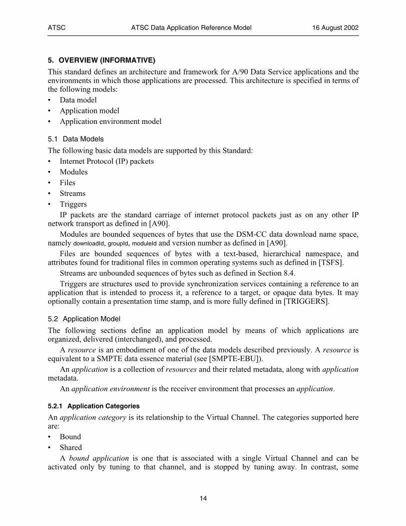
4. SYSTEM ASSUMPTIONS (INFORMATIVE)
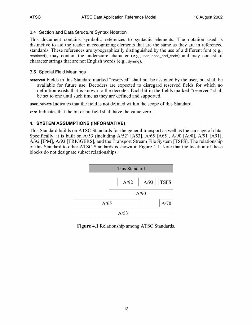
This Standard builds on ATSC Standards for the general transport as well as the carriage of data. Specifically, it is built on A/53 (including A/52) [A53], A/65 [A65], A/90 [A90], A/91 [A91], A/92 [IPM], A/93 [TRIGGERS], and the Transport Stream File System [TSFS]. The relationship of this Standard to other ATSC Standards is shown in Figure 4.1. Note that the location of these blocks do not designate subset relationships.
A/65
A/53
A/90
A/92 A/93 TSFS
This Standard
A/70
Figure 4.1 Relationship among ATSC Standards.
ATSC ATSC Data Application Reference Model 16 August 2002
14
5. OVERVIEW (INFORMATIVE)
This standard defines an architecture and framework for A/90 Data Service applications and the environments in which those applications are processed. This architecture is specified in terms of the following models: • Data model • Application model • Application environment model
5.1 Data Models
The following basic data models are supported by this Standard: • Internet Protocol (IP) packets • Modules • Files • Streams • Triggers
IP packets are the standard carriage of internet protocol packets just as on any other IP network transport as defined in [A90].
Modules are bounded sequences of bytes that use the DSM-CC data download name space, namely downloadId, groupId, moduleId and version number as defined in [A90].
Files are bounded sequences of bytes with a text-based, hierarchical namespace, and attributes found for traditional files in common operating systems such as defined in [TSFS].
Streams are unbounded sequences of bytes such as defined in Section 8.4. Triggers are structures used to provide synchronization services containing a reference to an
application that is intended to process it, a reference to a target, or opaque data bytes. It may optionally contain a presentation time stamp, and is more fully defined in [TRIGGERS].
5.2 Application Model
The following sections define an application model by means of which applications are organized, delivered (interchanged), and processed.
A resource is an embodiment of one of the data models described previously. A resource is equivalent to a SMPTE data essence material (see [SMPTE-EBU]).
An application is a collection of resources and their related metadata, along with application metadata.
An application environment is the receiver environment that processes an application.
5.2.1 Application Categories
An application category is its relationship to the Virtual Channel. The categories supported here are: • Bound • Shared
A bound application is one that is associated with a single Virtual Channel and can be activated only by tuning to that channel, and is stopped by tuning away. In contrast, some
ATSC ATSC Data Application Reference Model 16 August 2002
15
applications may be associated with a collection of related Virtual Channels, such as a set of ATSC minor channels within a single major channel (e.g., all XBC channels: 10.1 and 10.2, etc). It is desirable that such an application survive channel changes as long as the receiver stays within the associated channel group. An example is a broadcaster-specific Electronic Program Guide (EPG) that provides a small navigation bar on the bottom of the screen for a group of related channels. The receiver should recognize the fact that the same application is signaled on the multiple channels that the viewer is switching from and to, and not stop, then reload and restart the application. However, such an application should suspend during this channel transition. This is a shared application.
It is often desirable that the execution of certain applications is independent of channel changes. An example of such unbound applications is a non-broadcaster-specific EPG. The application resides in the receiver after being downloaded through either a virtual channel or other means. A viewer can activate and stop the application regardless which virtual channel is being watched. The states and transitions needed for the category of Unbound Application are outside the scope of this Standard.
5.2.2 Application Announcement
The future availability of an application for possible processing and presentation by an application environment may be announced in the transport. The intention of application announcement is to notify the receiver of the future availability of the application so that the receiver can take an appropriate action to schedule use of the application and/or inform the viewer. This is defined in Section 11.2.
The announcement of an application is characterized by its metadata: • Profile and Level1 • Availability Time and Duration • Rating Information • Language and the following optional metadata: • Title • Description
Note that [A90] provides for announcement of events within Data Services only and not individual applications.
5.2.3 Application Signaling
The availability of an application for processing and presentation by an application environment is signaled in the transport. This is defined in Section 11.3.
The signaling of an application is accompanied by metadata that describes all the resources that embody the application. This application signaling metadata is as follows: • Application Identifier • Profile and Level2 • Category (as defined in 5.2.1) • Invocation Directive (bootstrap or runtime)3
1 This is the profile and level of the application, and not the data service profile and level defined in A/90. 2 op. cit.
ATSC ATSC Data Application Reference Model 16 August 2002
16
• Identifier of the Root Resource It is not expected that this metadata will be presented to a viewer, but will instead be used by
the application environment for processing the application.
5.2.4 Resource Signaling
Each resource listed in the application can include the following metadata: • Identifier • Content Type In addition, for Module data models, there is the additional metadata: • Acquisition Directive And, for File data models: • Miscellaneous Attributes as defined in [TSFS].
A resource identifier takes the form of an absolute universal resource identifier (URI) according to [URI]. This identifier is globally unique. A resource content type takes the form of a MIME media type [MIME]. Note that MIME media types may take parameters.
An optional acquisition directive is conveyed by means of an Application Descriptor, as defined in [TRIGGER], that indicates to the application environment that it should promptly acquire the resource, with the expectation that a trigger referencing the resource will be arriving soon.
5.3 Security and Policy
There is no requirement for added support at the transport level for security models or conditional access. This topic is not covered in this document, and the reader is referred to [A70].
However, content authors and broadcasters may wish to assert their policy positions with respect to control of certain actions a data service may take. This takes the form of asserting a denial of certain “policies,” where each “policy” gives permission for a certain specific type of action in the application environment. In the absence of any explicit assertion to deny a policy, any permissions affected by the policy remain grantable. To assert denial of policies a Broadcaster Policy Descriptor is transmitted. In general, this will result in one or more permissions being denied.
6. APPLICATION STATE MODEL
At this time, the ATSC A/90 Service Description Framework (SDF) provides limited capabilities to signal an application software environment for state changes. The state model defined here makes use of the available facilities to define some useful application behavior for the application environment.
6.1 Background on SDF and PSI Facilities (Informative)
Data services for a Virtual Channel are defined and signaled by the Data Service Table (DST). Each DST contains a list of applications that are currently available in the broadcast stream. Each
3 Strictly speaking, the “bootstrap” and “runtime” directives apply to resources, not applications. As applied to
applications, “bootstrap” is used here to mean that the application has at least one resource with the “bootstrap” directive, and “runtime” is used here to mean that it has no resources with the “bootstrap” directive.
ATSC ATSC Data Application Reference Model 16 August 2002
17
application is composed of one or more taps that reference specific resources or groups of resources in the broadcast stream.
Each tap in the application loop contains an action_type that identifies the data item as “run-time data” or “bootstrap data”. The latter is meant to indicate that the item referenced by the tap is to be loaded and executed by the application environment.
Receipt of a DST by the receiver signals the presence of a data service and its applications. It minimally defines for each application one or more “root” resources required to activate the application via the tap(s) containing the action_type set to “bootstrap data” (0x01). There may be more than one application that is activated in this manner.
When a new DST is received that omits a previously signaled application, this means that the application is no longer available in the broadcast. The lack of receipt of any DST over some period of time has no meaning since the recommended minimum cycle time is not required.
Since exact DST emission frequency is unknown4, it cannot reliably be used for any “fast” signaling by including descriptors, for example, to signal application state changes. More importantly, it cannot be counted on being emitted when an application is not being broadcast, particularly during insertions of commercials at a broadcaster.
There are, however, strict timing requirements on the Program Map Table (PMT). The PMT is a reliable source of what streams are currently valid with “good” time resolution (400ms maximum).
6.2 Events
Based on the available SDF and PSI facilities described previously, the following events shall have the indicate meaning: • New – receipt of a DST that contains a new application with the action_type set to “bootstrap
data” • AppGone – receipt of a DST that omits a previous application • DSTGone – receipt of a PMT that omits the DST Program Element (0x95), or lack of a PMT
with the same program_number after the minimum cycle time. • Continue – receipt of a DST with the same application • ChanChange – when the channel is changed due to a Directed Channel Change descriptor in
the transport. An application shall be considered to be a new application if an instance of the application is
not currently in a state other than Unloaded and if one of the following holds: (1) the previous DST did not signal the presence of the application and the current DST signals the application with action_type set to 0x01 (bootstrap data), or (2) the previous DST signaled the presence of the application with action_type set to 0x00 (runtime data) and the current DST signals the application with action_type set to 0x01 (bootstrap data).
The following events are from the application environment: • LoadComplete – all minimally required resources (as defined by the application
environment) have been loaded. • Terminate - resources need to be freed by the application. • Load – loads an application
4 Section 11 provides a recommendation, but it cannot be counted on.
ATSC ATSC Data Application Reference Model 16 August 2002
18
• ChanChange – when the channel is changed as a result of an action from the application environment (including a viewer initiated channel change). The above events provide the inputs to a basic application state model. The application
environment should respond to or assert all the above events in a manner consistent with the following subsections. Also note that the ChanChange events have the same state transitions whether it was initiated by the transport or by the application environment. Hence it appears only once in the discussion that follows. Note also that a single DST may generate multiple events for multiple applications.
The above events are derived in part by the receiver noting changes to the version_number field in the DST and the PMT TS_program_map_section for the related virtual channel. However, it is the responsibility of the application environment to fully monitor all ATSC A/65 and A/90 tables and descriptors to react to other changes and events it deems relevant. A change in the DST table version_number field may or may not indicate one of the above transport events.
6.3 States
For the purpose of the model, each application in the application environment shall be considered to be in one of four abstract states: • Unloaded – consuming no receiver resources whatsoever, and is for all intents unknown to
the application environment. • Loading – when the application environment has begun the loading process, but is not able to
execute yet due to missing critical resources. • Running – loaded all minimally required resources (as defined by the application
environment) and is executing. • Suspended – previously running and has stopped, but is still consuming resources and its
state is preserved. The Unloaded and Loading states are not visible to the application itself. And, all of these
states are abstract. A specific instance of an application environment may not actually implement these states.
Note: Specific application environments may employ their own, possibly different state models; these are considered to be independent of the state model prescribed here.
6.4 State Transitions
An application shall start and end in the Unloaded state. An application shall enter the Running state upon completion (as defined by the application
environment and signaled by the LoadComplete event) of the loading process while in the Loading state.
An application shall transition from Suspended to Unloaded when the environment decides that its resources are needed by another application in the Loading or Running state, as signaled by the Terminate event.
An application shall transition from Suspended to Running when a DST is received that contains that application (Continue).
The application environment may control the state changes with the explicit event, Load. Note that this model implicitly handles the application category semantics defined in 5.2.1 by
always suspending an application on channel change. Thus, no additional explicit signaling is required to distinguish them. The complete state transitions are specified in Table 6.1.
ATSC ATSC Data Application Reference Model 16 August 2002
19
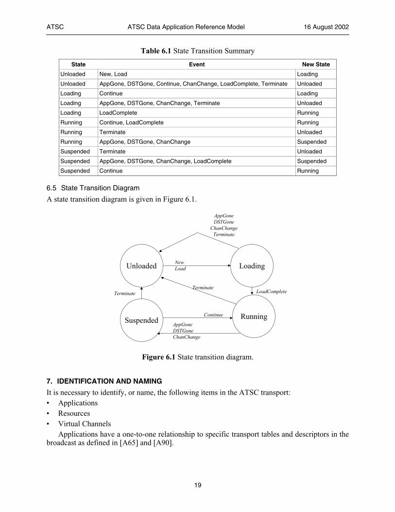
Table 6.1 State Transition Summary
State Event New State
Unloaded New, Load Loading
Unloaded AppGone, DSTGone, Continue, ChanChange, LoadComplete, Terminate Unloaded
Loading Continue Loading
Loading AppGone, DSTGone, ChanChange, Terminate Unloaded
Loading LoadComplete Running
Running Continue, LoadComplete Running
Running Terminate Unloaded
Running AppGone, DSTGone, ChanChange Suspended
Suspended Terminate Unloaded
Suspended AppGone, DSTGone, ChanChange, LoadComplete Suspended
Suspended Continue Running
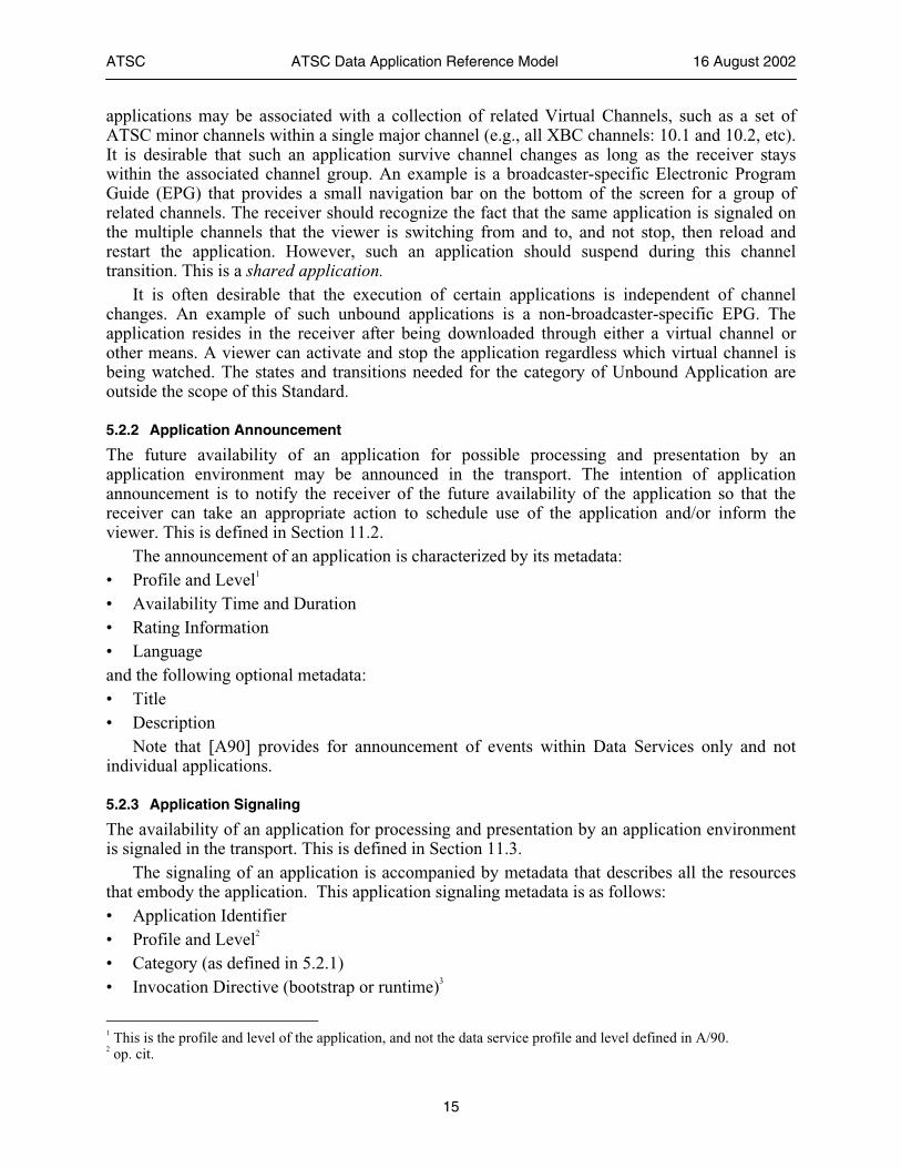
6.5 State Transition Diagram
A state transition diagram is given in Figure 6.1.
Unloaded Loading
Suspended Running
New Load
LoadComplete
AppGone DSTGone ChanChange
Terminate
Continue
Terminate
AppGone DSTGone
ChanChange Terminate
Figure 6.1 State transition diagram.
7. IDENTIFICATION AND NAMING
It is necessary to identify, or name, the following items in the ATSC transport: • Applications • Resources • Virtual Channels
Applications have a one-to-one relationship to specific transport tables and descriptors in the broadcast as defined in [A65] and [A90].
ATSC ATSC Data Application Reference Model 16 August 2002
20
Application resources are identified in part by a Tap in the application loop of the Data Service Table (DST). However, a Tap can point to more than one resource.
Identification for applications, resources, and Virtual Channels shall be accomplished with Uniform Resource Identifiers (URI's). There are two forms of broadcast-related URI schemes. These forms are “tv:” [URI-TV] and “lid:” [URI-LID].
Any given item may have more than one URI associated with it. For example, a Virtual Channel may have a URI designating the broadcast station as well as its affiliated network.
Conversely, any given URI may be associated with more than one item. For example, a URI referencing a resource may be associated with equivalent (but not necessarily identical) resources, possibly of different content types.
URIs operate on a tagged basis. That is, the items identified by URIs are explicitly bound in some manner with the URI string values in the transport. When the receiver attempts to resolve a URI to the item that it references, it conceptually searches through its memory and/or the broadcast until it finds one or more matches. It then returns a (possibly empty) list of matching references.
When a URI is bound to more than one item, the different resources are considered identical from the application’s viewpoint and can be used interchangeably. This does not mean they are identical, only that from the author's point of view, it does not matter which is chosen. In complex transports, this may result in multiple matches.
URIs identify an individual item. If a given item has multiple parts, the individual parts may be identified by adding fragment and/or query suffixes to the URI reference. Per [URI], the interpretation of fragments and queries is content type dependent.
7.1 The tv: Scheme
The tv: URI scheme shall be used to refer to a Virtual Channel, and is defined in RFC 2838 [URI-TV]. Note that the use of just "tv:" refers to the currently streaming video/audio content being displayed to the viewer. If the receiver has more than one tuner and decoder, then the selection is the "main" content as determined by the receiver. So, use of the full form, “tv:<service_name>” may cause the receiver to tune to that Virtual Channel, or it may not in the case of multiple tuners and the “main” content is determined by the receiver to not be on that Virtual Channel. This is also affected by the Broadcast Policy Descriptor described in this document, as well as the A/65 DCC mechanisms that take precedence over data service application execution.
Note that the resolution algorithm for tv:<service_name> requires that the channels be labeled accordingly (see Service Name Descriptor below).
Query syntax is permitted and is content type dependent as more fully defined below.
7.2 The lid: Scheme
A “lid” URI is defined by [URI-LID] and has the form:
lid://name/path?query#fragment
where name is a registered domain name and path is a unique path name assigned by the content author that owns the domain name. The domain name is used to guarantee uniqueness between organizations and the path provides a mechanism for managing uniqueness within an organization. Per [URI-LID], use of the uuid form of name is deprecated. However, designers
ATSC ATSC Data Application Reference Model 16 August 2002
21
should be aware that it is used in some existing applications and may appear in the received bitstream.
These URIs are assigned by the organization responsible for creating the resource that they designate. For example, given an organization that creates an application, then the URI that designates that application would often use a domain name that is associated with that organization.
A receiver needs to be able to receive URIs and their associated resources from an arbitrary combination of Virtual Channels or transport streams without worrying about name space collisions. Furthermore, a receiver needs to be able to record (either permanently or in a cache) an arbitrary subset of a broadcast and “replay” it at any time, again without having to worry about name space collisions.
Lid: may refer to the following broadcast resources: • Module • File • Stream • (stream of) IP packets
Resources are identified (labeled) in the broadcast, and references are made to those resources by the application environment. The permissible syntax is slightly different for each. Fragment or query syntax shall not be used in the transport labeling of the resources. Regarding references by the application environment: • Lid: may have a fragment component. The fragment is interpreted in a content type
dependent manner and is outside the scope of this Standard. • Lid: may have a query component. The query is interpreted in a content type dependent
manner as defined below.
7.3 Content Types and Their URI Dependent Behavior
When used to refer to a Virtual Channel, “tv:<service_name>” shall refer only to the content type, "video/mpeg". The lid: URI may refer to a module or file with the content type, “video/mpeg”.
The “video/mpeg” content type supports the query syntax, extending [URI-LID], and [URI-TV]. The query string is of the form:
scheme[?component[;component]*]
scheme = any valid URI scheme that resolves to a content type of “video/mpeg”
component = ["video"|"audio"|"data"|"dtvcc"[=component_name]]
Note that per [URI], Section 3.4, reserved characters must be escaped. The query component, “video”, shall refer to the content’s video elementary stream. Note
that this video encoding content is constrained by Table 3 of [A53] for tv: scheme references. The query component, “audio” refers to the channel's “current” audio Program Element. The
“current” video or audio is intended to be the one currently playing, or otherwise determined by the receiver to be the “main” one. In the case of multiple audio tracks, this is the audio that is currently selected when using “tv:”, the default audio for the receiver in the case of “tv:<service_name>”, and the default language audio in the case of lid:.
The query component, “data”, refers to the aggregate of Program Elements that comprise the ATSC Data Service, including the DST and related tables of the service description framework.
ATSC ATSC Data Application Reference Model 16 August 2002
22
The query component, “dtvcc”, refers to the closed captioning stream as defined in Section 8.4.1.
Each query component may contain the optional assignment of a string value defined as “component_name” which may be encoded as Unicode. This is used to refer to a specific Program Element as labeled by the component name descriptor defined in [A65], section 6.7.8. The program element specified is the program element of the specified type for which any of the strings in the “number_strings” loop of the multiple_string_structure for the component_name of the program element matches the string value in the query component.
The above queries may be combined as provided in the BNF above. For example,
tv:xbc.com?video;audio=crowd%20noise;data,dtvcc.
The above would resolve to a stream with all the basic Virtual Channel components, but specifically including the audio track containing the “crowd noise” as labeled by the component name descriptor.
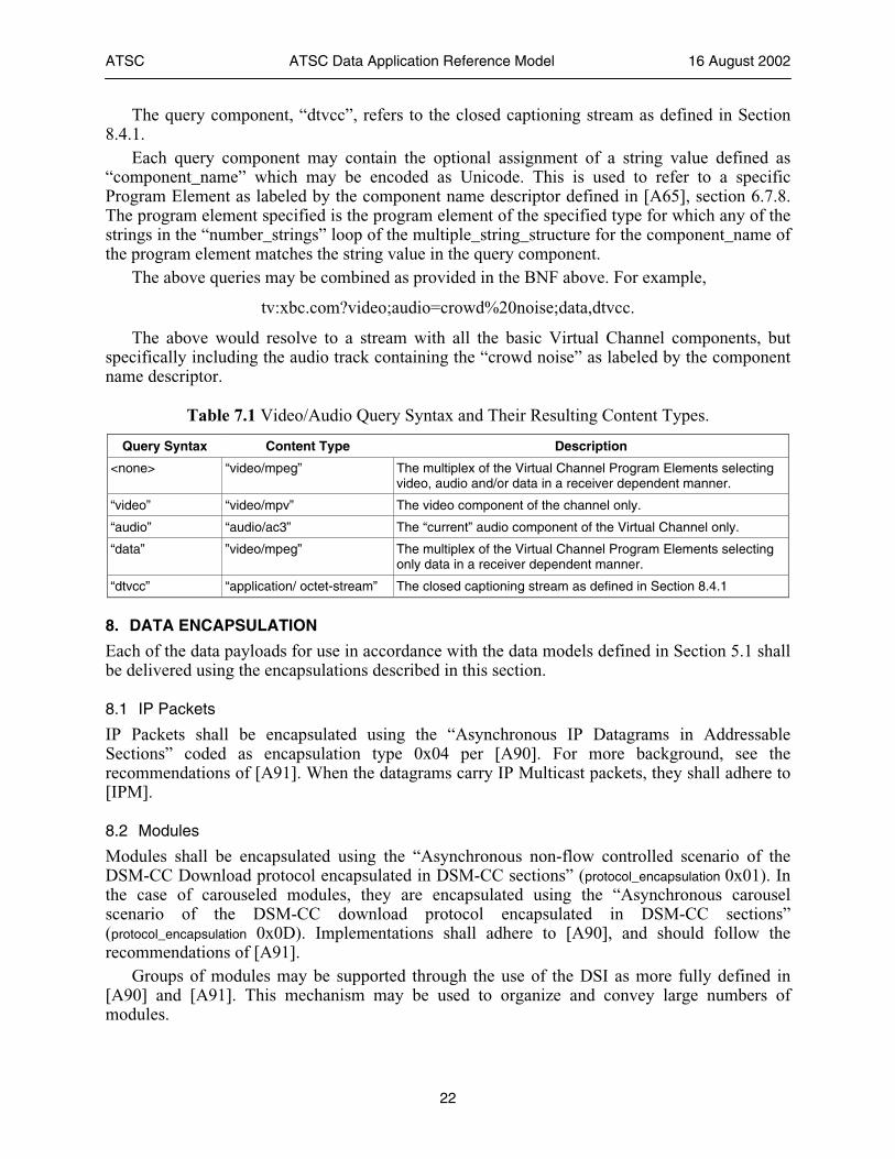
Table 7.1 Video/Audio Query Syntax and Their Resulting Content Types.
Query Syntax Content Type Description
<none> “video/mpeg” The multiplex of the Virtual Channel Program Elements selecting video, audio and/or data in a receiver dependent manner.
“video” “video/mpv” The video component of the channel only.
“audio” “audio/ac3” The “current” audio component of the Virtual Channel only.
“data” ”video/mpeg” The multiplex of the Virtual Channel Program Elements selecting only data in a receiver dependent manner.
“dtvcc” “application/ octet-stream” The closed captioning stream as defined in Section 8.4.1
8. DATA ENCAPSULATION
Each of the data payloads for use in accordance with the data models defined in Section 5.1 shall be delivered using the encapsulations described in this section.
8.1 IP Packets
IP Packets shall be encapsulated using the “Asynchronous IP Datagrams in Addressable Sections” coded as encapsulation type 0x04 per [A90]. For more background, see the recommendations of [A91]. When the datagrams carry IP Multicast packets, they shall adhere to [IPM].
8.2 Modules
Modules shall be encapsulated using the “Asynchronous non-flow controlled scenario of the DSM-CC Download protocol encapsulated in DSM-CC sections” (protocol_encapsulation 0x01). In the case of carouseled modules, they are encapsulated using the “Asynchronous carousel scenario of the DSM-CC download protocol encapsulated in DSM-CC sections” (protocol_encapsulation 0x0D). Implementations shall adhere to [A90], and should follow the recommendations of [A91].
Groups of modules may be supported through the use of the DSI as more fully defined in [A90] and [A91]. This mechanism may be used to organize and convey large numbers of modules.
ATSC ATSC Data Application Reference Model 16 August 2002
23
8.3 Files
Files shall be encapsulated according to [TSFS].
8.4 Streams
Streams shall be encapsulated using either of the following asynchronous stream encapsulations: • Asynchronous non-flow controlled scenario of the DSM-CC Download protocol
encapsulated in DSM-CC sections (encapsulation_type 0x01) • Proprietary Data Piping (encapsulation_type 0x0B) In either case, the receiver shall adhere to [A90].
Also, for the DSM-CC encapsulation, the moduleSize shall be set to zero in the DII. Since there is only a single module in the download scenario is this streaming case, the DII may be emitted infrequently. As recommended in [A91], only a single level download scenario should be used, so the DSI shall not be emitted. The recommendations of [A91] should be followed.
8.4.1 MPEG-2 Video Picture UserData (DTVCC)
Other types of streams that may be present in an ATSC broadcast stream are the closed captioning streams and other data streams that may appear in the user_data area in the video frame headers, as specified by [A/53], Annex A, Section 5.2.2, see also [ATVCC] and [DTVCC]. These streams are outside the scope of this Standard.
8.5 Triggers
Triggers shall be encapsulated according to [TRIGGERS]. Both synchronized and asynchronous triggers may be used; furthermore, they may be used to refer to targets in the transport or delivery of event payloads. In the case of asynchronous event payloads, further constraints apply as defined in the following subsection.
8.5.1 Asynchronous Events
For asynchronous triggers carrying event payloads, and not referring to targets in the transport stream, the trigger event structure fields shall be constrained as follows:
event_type – shall be set to 0x00 (Trigger Event). target_type and target_length – shall both be set to 0x00. user_data_length – shall be set to the length of the event payload. When the triggers for more than one application are not multiplexed into the same Program
Element, then the app_id_byte_length shall be set to zero. When the data server has chosen to multiplex triggers from more than one application into a single Program Element, then the app_id_byte_length shall be set to 0x0012 (1810); app_id_description shall be set to 0x0000; and app_id_bytes shall be set to the binary UUID of the application to which the trigger belongs.
9. DESCRIPTORS AND STRUCTURES
In order to provide adequate announcement and signaling, several new descriptors and structures are needed. These are defined in this section. • Compatibility Wrapper • Identifier • Service Name
ATSC ATSC Data Application Reference Model 16 August 2002
24
• Broadcaster Policy
9.1 Compatibility Wrapper Descriptor
The DSM-CC Compatibility Descriptor is not an MPEG-2 System descriptor due to the 16-bit length field, and thus it cannot go into the standard descriptor loops of many A/65 and A/90 tables, such as the EIT and DET. Therefore, some means is needed to carry the compatibility data in an MPEG compliant manner in the appropriate descriptor loops of these tables. To meet this need, a Compatibility Wrapper Descriptor is defined and used to carry the Compatibility Descriptor.
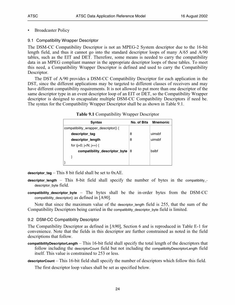
The DST of A/90 provides a DSM-CC Compatibility Descriptor for each application in the DST, since the different applications may be targeted to different classes of receivers and may have different compatibility requirements. It is not allowed to put more than one descriptor of the same descriptor type in an event descriptor loop of an EIT or DET, so the Compatibility Wrapper descriptor is designed to encapsulate multiple DSM-CC Compatibility Descriptors if need be. The syntax for the Compatibility Wrapper Descriptor shall be as shown in Table 9.1.
Table 9.1 Compatibility Wrapper Descriptor
Syntax No. of Bits Mnemonic
compatibility_wrapper_descriptor() {
descriptor_tag 8 uimsbf
descriptor_length 8 uimsbf
for (j=0; j<N; j++) {
compatibility_descriptor_byte 8 bslbf
}
}
descriptor_tag – This 8 bit field shall be set to 0xAE.
descriptor_length – This 8-bit field shall specify the number of bytes in the compatibility_-
descriptor_byte field.
compatibility_descriptor_byte – The bytes shall be the in-order bytes from the DSM-CC compatibility_descriptor() as defined in [A90].
Note that since the maximum value of the descriptor_length field is 255, that the sum of the Compatibility Descriptors being carried in the compatibility_descriptor_byte field is limited.
9.2 DSM-CC Compatibility Descriptor
The Compatibility Descriptor as defined in [A90], Section 6 and is reproduced in Table E-1 for convenience. Note that the fields in this descriptor are further constrained as noted in the field descriptions that follow.
compatibilityDescriptorLength – This 16-bit field shall specify the total length of the descriptors that follow including the descriptorCount field but not including the compatibilityDescriptorLength field itself. This value is constrained to 253 or less.
descriptorCount – This 16-bit field shall specify the number of descriptors which follow this field.
The first descriptor loop values shall be set as specified below.
ATSC ATSC Data Application Reference Model 16 August 2002
25
descriptorType – This 8-bit field shall be set to 0x02 to indicate that this is describing system software per [DSMCC].
descriptorLength – This 8-bit field shall specify the total length of the descriptor, not including the descriptorType and descriptorLength fields.
specifierType – This 8-bit field shall be set to 0x01 to indicate that the specifierData field is an OUI per [DSMCC].
specifierData – This 24-bit field shall be set to the OUI of ATSC, “0x0009790”. This field, along with the specifierType and descriptorType, uniquely scope the model and version fields that follow.
model – This 16-bit field as defined in DSM-CC. When the OUI is set to the value for ATSC, then this field shall indicate the specific application environment defined by ATSC. All values other than those listed in the ATSC Registry are ATSC Reserved. See the ATSC Registry for assignments.
version – This 16-bit field is set to a value that is dependent on the model field. The standard which implements a specific application environment shall define the semantics of this field. For example, it could be used to define profiles and levels of the environment that this application is compatible with.
subDescriptorCount – This 8-bit field shall represent the number of private subDescriptors for the descriptor. No subDescriptors are defined in this Standard and users shall not define any subDescriptors when the OUI is set to the value for “ATSC” as defined here. They may only be defined for other OUI values.
The subDescriptor() structure contains additional private descriptors whose semantics are specified by the organization identified by the specifier fields. The subDescriptor structure and syntax is defined in [DSMCC].
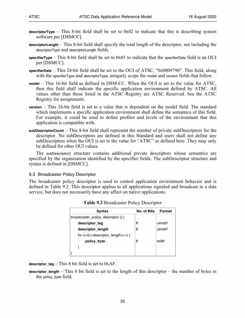
9.3 Broadcaster Policy Descriptor
The broadcaster policy descriptor is used to control application environment behavior and is defined in Table 9.2. This descriptor applies to all applications signaled and broadcast in a data service, but does not necessarily have any affect on native applications.
Table 9.2 Broadcaster Policy Descriptor
Syntax No. of Bits Format
broadcaster_policy_descriptor () {
descriptor_tag 8 uimsbf
descriptor_length 8 uimsbf
for (i=0;i<descriptor_length;i++) {
policy_byte 8 bslbf
}
}
descriptor_tag – This 8 bit field is set to 0xAF.
descriptor_length – This 8 bit field is set to the length of this descriptor – the number of bytes in the policy_byte field.
ATSC ATSC Data Application Reference Model 16 August 2002
26
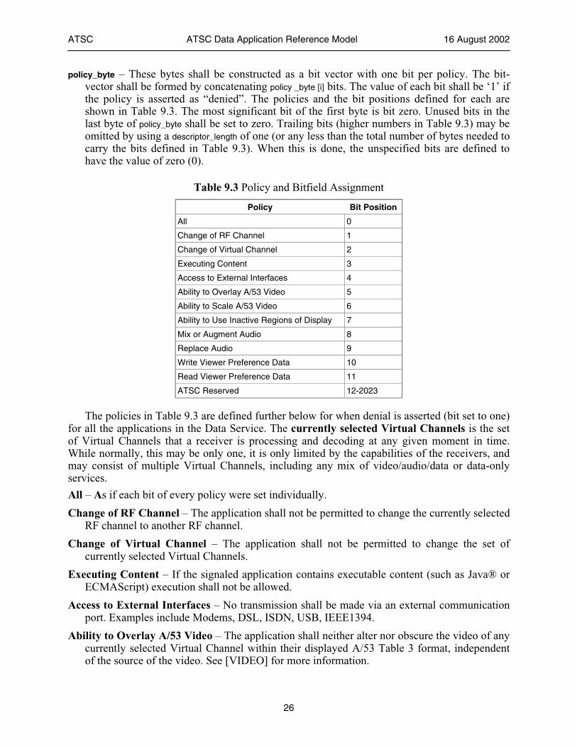
policy_byte – These bytes shall be constructed as a bit vector with one bit per policy. The bit-vector shall be formed by concatenating policy _byte [i] bits. The value of each bit shall be ‘1’ if the policy is asserted as “denied”. The policies and the bit positions defined for each are shown in Table 9.3. The most significant bit of the first byte is bit zero. Unused bits in the last byte of policy_byte shall be set to zero. Trailing bits (higher numbers in Table 9.3) may be omitted by using a descriptor_length of one (or any less than the total number of bytes needed to carry the bits defined in Table 9.3). When this is done, the unspecified bits are defined to have the value of zero (0).
Table 9.3 Policy and Bitfield Assignment
Policy Bit Position
All 0
Change of RF Channel 1
Change of Virtual Channel 2
Executing Content 3
Access to External Interfaces 4
Ability to Overlay A/53 Video 5
Ability to Scale A/53 Video 6
Ability to Use Inactive Regions of Display 7
Mix or Augment Audio 8
Replace Audio 9
Write Viewer Preference Data 10
Read Viewer Preference Data 11
ATSC Reserved 12-2023
The policies in Table 9.3 are defined further below for when denial is asserted (bit set to one) for all the applications in the Data Service. The currently selected Virtual Channels is the set of Virtual Channels that a receiver is processing and decoding at any given moment in time. While normally, this may be only one, it is only limited by the capabilities of the receivers, and may consist of multiple Virtual Channels, including any mix of video/audio/data or data-only services.
All – As if each bit of every policy were set individually.
Change of RF Channel – The application shall not be permitted to change the currently selected RF channel to another RF channel.
Change of Virtual Channel – The application shall not be permitted to change the set of currently selected Virtual Channels.
Executing Content – If the signaled application contains executable content (such as Java® or ECMAScript) execution shall not be allowed.
Access to External Interfaces – No transmission shall be made via an external communication port. Examples include Modems, DSL, ISDN, USB, IEEE1394.
Ability to Overlay A/53 Video – The application shall neither alter nor obscure the video of any currently selected Virtual Channel within their displayed A/53 Table 3 format, independent of the source of the video. See [VIDEO] for more information.
ATSC ATSC Data Application Reference Model 16 August 2002
27
Ability to Scale A/53 Video – The receiver native processing determines the size of a display based on factors outside the scope of this Standard. If this permission is denied, then the application shall not alter the size of the video being displayed independent of the source of the video. See [VIDEO] for more information.
Ability to Use Inactive Regions of Display – The application shall neither alter nor obscure the video of the currently selected Virtual Channels outside their displayed A/53 “Table 3” format, independent of the source of the video. For example: If a given video has nominally dark areas either to the sides of the A/53 video (4:3 picture on a 16:9 glass) or on the top and bottom of the A/53 video (16:9 picture on 4:3 glass) and this permission is denied then the application shall not use either of those areas when they are present. See [VIDEO] for more information.
Mix or Augment Audio – A/52 audio is not mixed with anything else, or altered in any way.
Replace Audio – A/52 audio is not muted or replaced.
Write Viewer Preference Data – The application is prohibited from altering the viewer preference or any viewer-related data.
Read Viewer Preference Data – The application is prohibited from reading the viewer preference data.
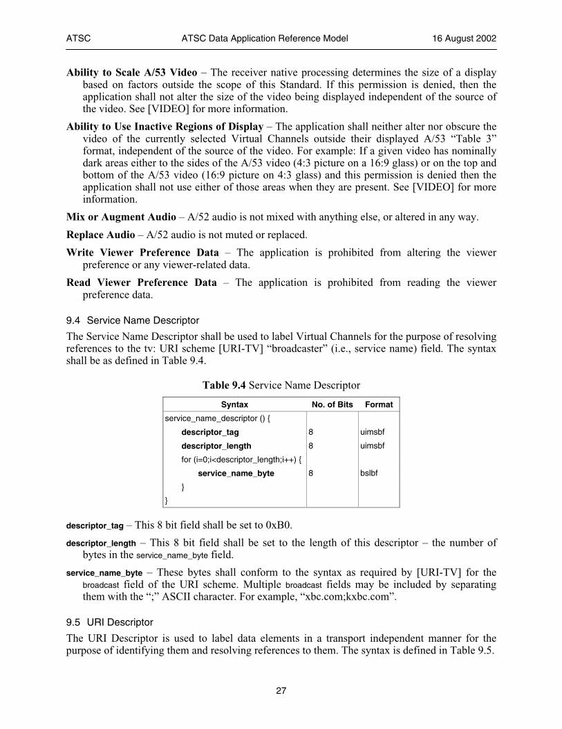
9.4 Service Name Descriptor
The Service Name Descriptor shall be used to label Virtual Channels for the purpose of resolving references to the tv: URI scheme [URI-TV] “broadcaster” (i.e., service name) field. The syntax shall be as defined in Table 9.4.
Table 9.4 Service Name Descriptor
Syntax No. of Bits Format
service_name_descriptor () {
descriptor_tag 8 uimsbf
descriptor_length 8 uimsbf
for (i=0;i<descriptor_length;i++) {
service_name_byte 8 bslbf
}
}
descriptor_tag – This 8 bit field shall be set to 0xB0.
descriptor_length – This 8 bit field shall be set to the length of this descriptor – the number of bytes in the service_name_byte field.
service_name_byte – These bytes shall conform to the syntax as required by [URI-TV] for the broadcast field of the URI scheme. Multiple broadcast fields may be included by separating them with the “;” ASCII character. For example, “xbc.com;kxbc.com”.
9.5 URI Descriptor
The URI Descriptor is used to label data elements in a transport independent manner for the purpose of identifying them and resolving references to them. The syntax is defined in Table 9.5.
ATSC ATSC Data Application Reference Model 16 August 2002
28
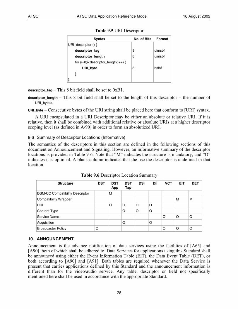
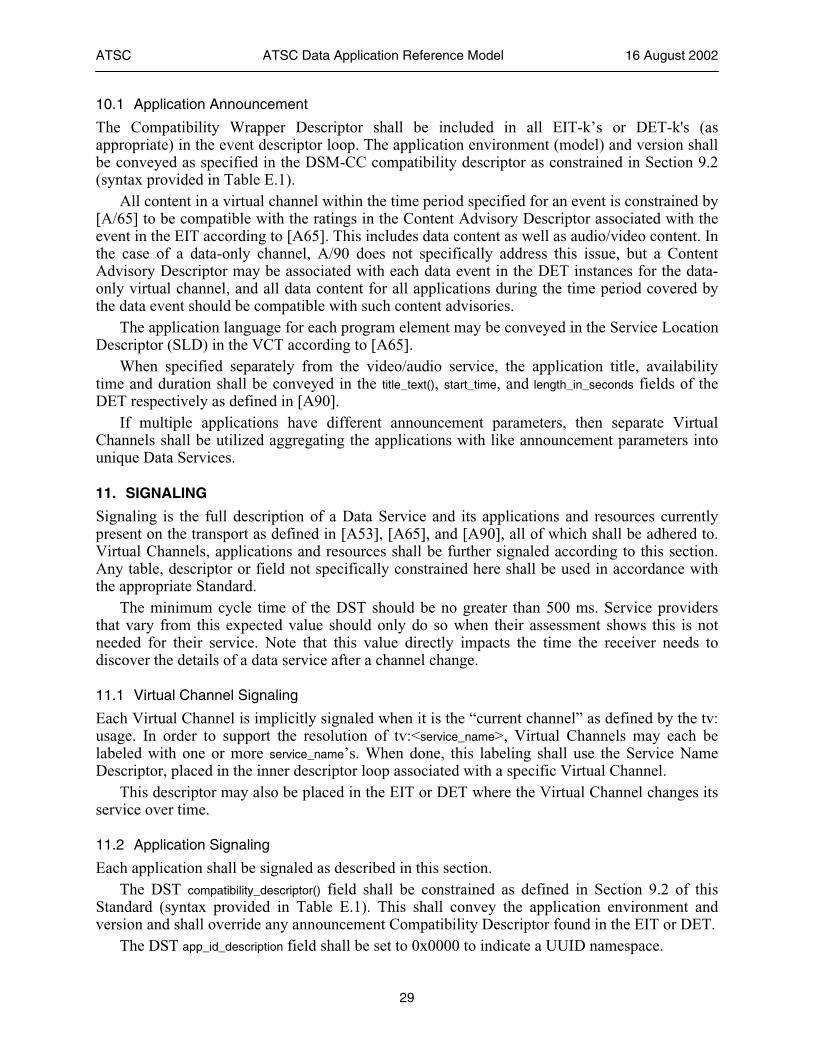
Table 9.5 URI Descriptor
Syntax No. of Bits Format
URI_descriptor () {
descriptor_tag 8 uimsbf
descriptor_length 8 uimsbf
for (i=0;i<descriptor_length;i++) {
URI_byte 8 bslbf
}
}
descriptor_tag – This 8 bit field shall be set to 0xB1.
descriptor_length – This 8 bit field shall be set to the length of this descriptor – the number of URI_byte’s.
URI_byte – Consecutive bytes of the URI string shall be placed here that conform to [URI] syntax.
A URI encapsulated in a URI Descriptor may be either an absolute or relative URI. If it is relative, then it shall be combined with additional relative or absolute URIs at a higher descriptor scoping level (as defined in A/90) in order to form an absolutized URI.
9.6 Summary of Descriptor Locations (Informative)
The semantics of the descriptors in this section are defined in the following sections of this document on Announcement and Signaling. However, an informative summary of the descriptor locations is provided in Table 9-6. Note that “M” indicates the structure is mandatory, and “O” indicates it is optional. A blank column indicates that the use the descriptor is undefined in that location.
Table 9.6 Descriptor Location Summary
Structure DST DST App
DST Tap
DSI DII VCT EIT DET
DSM-CC Compatibility Descriptor M
Compatibility Wrapper M M
URI O O O O
Content Type O O O
Service Name O O O
Acquisition O O
Broadcaster Policy O O O O
10. ANNOUNCEMENT
Announcement is the advance notification of data services using the facilities of [A65] and [A90], both of which shall be adhered to. Data Services for applications using this Standard shall be announced using either the Event Information Table (EIT), the Data Event Table (DET), or both according to [A90] and [A91]. Both tables are required whenever the Data Service is present that carries applications defined by this Standard and the announcement information is different than for the video/audio service. Any table, descriptor or field not specifically mentioned here shall be used in accordance with the appropriate Standard.
ATSC ATSC Data Application Reference Model 16 August 2002
29
10.1 Application Announcement
The Compatibility Wrapper Descriptor shall be included in all EIT-k’s or DET-k's (as appropriate) in the event descriptor loop. The application environment (model) and version shall be conveyed as specified in the DSM-CC compatibility descriptor as constrained in Section 9.2 (syntax provided in Table E.1).
All content in a virtual channel within the time period specified for an event is constrained by [A/65] to be compatible with the ratings in the Content Advisory Descriptor associated with the event in the EIT according to [A65]. This includes data content as well as audio/video content. In the case of a data-only channel, A/90 does not specifically address this issue, but a Content Advisory Descriptor may be associated with each data event in the DET instances for the data-only virtual channel, and all data content for all applications during the time period covered by the data event should be compatible with such content advisories.
The application language for each program element may be conveyed in the Service Location Descriptor (SLD) in the VCT according to [A65].
When specified separately from the video/audio service, the application title, availability time and duration shall be conveyed in the title_text(), start_time, and length_in_seconds fields of the DET respectively as defined in [A90].
If multiple applications have different announcement parameters, then separate Virtual Channels shall be utilized aggregating the applications with like announcement parameters into unique Data Services.
11. SIGNALING
Signaling is the full description of a Data Service and its applications and resources currently present on the transport as defined in [A53], [A65], and [A90], all of which shall be adhered to. Virtual Channels, applications and resources shall be further signaled according to this section. Any table, descriptor or field not specifically constrained here shall be used in accordance with the appropriate Standard.
The minimum cycle time of the DST should be no greater than 500 ms. Service providers that vary from this expected value should only do so when their assessment shows this is not needed for their service. Note that this value directly impacts the time the receiver needs to discover the details of a data service after a channel change.
11.1 Virtual Channel Signaling
Each Virtual Channel is implicitly signaled when it is the “current channel” as defined by the tv: usage. In order to support the resolution of tv:<service_name>, Virtual Channels may each be labeled with one or more service_name’s. When done, this labeling shall use the Service Name Descriptor, placed in the inner descriptor loop associated with a specific Virtual Channel.
This descriptor may also be placed in the EIT or DET where the Virtual Channel changes its service over time.
11.2 Application Signaling
Each application shall be signaled as described in this section. The DST compatibility_descriptor() field shall be constrained as defined in Section 9.2 of this
Standard (syntax provided in Table E.1). This shall convey the application environment and version and shall override any announcement Compatibility Descriptor found in the EIT or DET.
The DST app_id_description field shall be set to 0x0000 to indicate a UUID namespace.
ATSC ATSC Data Application Reference Model 16 August 2002
30
The DST app_id_byte field shall be set to a UUID as defined in [UUID], and shall be globally unique for all transports, including non-ATSC transports. The app_id_byte_length shall be set to 0x0012 (1810).
Each application in the DST shall signal at least one Tap. One or more Taps of each application may have their action_type field set to 0x01 (Bootstrap
data) to signal that this Tap should be loaded and executed by the application environment. All other Taps of an application shall set their action_type field to 0x00 (Run-time data). If the action_type field is set to 0x01, then that Tap is assumed to unambiguously signal a root resource. Note that this may result in a minimum of 2 or more Taps being defined per application. For example, one Tap may be used to signal a data carousel containing all the resources for the application, with action_type field set to 0x00, and another Tap may be used to signal a specific module within the carousel that contains the root resource, with action_type field set to 0x01.
11.3 Resource Signaling
In general, a single Tap in the Data Service Table can reference an individual resource, such as a file, or it may reference a collection of data resources, such as an entire file system.
Each resource referenced by a data service application's Taps, either directly or indirectly, shall be construed as belonging to (being in the scope of) the referencing application. All resources that belong to an application which are delivered through the transport stream shall be referenced by a Tap, either directly or indirectly.
Note: A Tap which references a collection of data resources, such as a transport stream file system, makes indirect reference to zero or more resources in accordance with what constitutes the collection of referenced resources.
Note: Multiple data service applications in a single or multiple data services may make reference to a single resource or collection of resources. In such a case, ownership of a resource is shared among all referencing applications.
The Tap protocol_encapsulation field should be constrained from [A90], Table 12.5 to be one of those listed in Table 11.1, plus what is needed for [TSFS].
Table 11.1 Protocol Encapsulations
Value Encapsulated Protocol
0x01 Asynchronous non-flow controlled scenario of the DSM-CC Download protocol encapsulated in DSM-CC sections
0x02 Non-streaming Synchronized Download protocol encapsulated in DSM-CC sections
0x04 Asynchronous IP datagrams in Addressable Sections
0x0B Proprietary Data Piping
0x0D Asynchronous carousel protocol of the DSM-CC Download protocol
The DST action_type field shall be set according to the section above on application signaling. The DST Tap selector() field values shall be constrained to those values specified in Table
12.9 of [A90] for those encapsulations listed in Table 11.1, and, in addition, those values specified by [TSFS].
Unless otherwise identified as a [TSFS] component, each Tap in the application may include in its tap_info loop one or more URI Descriptors using a URI as defined in [URI]. Multiple URIs may label each Tap. The use of relative URIs is permitted, in which case an absolutized URI shall be determined according to rules specified in Section 9.5. In all cases, each application
ATSC ATSC Data Application Reference Model 16 August 2002
31
resource shall be labeled with at least one absolutizable URI, whether directly via the use of a URI Descriptor in a Tap, indirectly via the use of multiple scoped relative URIs in a data carousel (i.e., by use of URI Descriptors in DII, DSI, and DST Application), or indirectly via TSFS component labeling.
Each Tap in the application that does not reference a [TSFS] component may include in its tap_info loop a Content Type Descriptor as defined in [TRIGGER] (syntax provided in Table E.2). The value of the contentTypeByte string could be, for example, “image/jpeg” to designate that the module this Tap points to contains a JPEG file.
Each Tap that has its action_type set to 0x01 shall contain a Content Type Descriptor. Each Tap that points to a module or group may contain a Content Type Descriptor to indicate
the content type of the resource or resources in the module or group, and may contain an Acquisition Descriptor to indicate that this resource or resources should be acquired by the receiver as more fully defined in [TRIGGER] (syntax provided in Table E.3). These descriptors may also be placed in the DSI or DII as appropriate when referring to modules or groups.
11.4 Broadcaster Policy
When a broadcaster desires to assert a constraint policy for one or more Virtual Channels, then the Broadcaster Policy Descriptor may be in the number_of_channels descriptor loop of the TVCT/CVCT (VCT)—constraining all contents of each Virtual Channel for which policies are being asserted. This only affects Virtual Channels that actually contain a Data Service, and produces no effect otherwise.
When a Data Service provider desires to assert constraint policies for its Data Service (which will then be carried on a Virtual Channel), then the Broadcaster Policy Descriptor may be in the outer descriptor loop of the DST—constraining all content of that Data Service.
This descriptor applies to all the applications in the Data Service of the Virtual Channel for which the policy is asserted. In the case where the currently selected Virtual Channels is more than one, and there is more than one video/audio service being processed, then this policy applies to the audio and video area under the control of the Virtual Channel in which the policy is present.
To construct the final policy list, the receiver is expected to perform the union (bitwise logical OR) of the policies in the descriptors in the VCT and the DST for each Virtual Channel. The default condition for each policy is zero when the policy is unspecified, or the descriptor is not present.
In the event of semantic conflict with the A/65 Directed Channel Change (DCC) descriptor, the action of the DCC descriptor shall take precedence.
Note that the policy applies equally to all the applications in a Data Service and does not provide any control of the individual application except in the case where there is only one application present in the Data Service.
11.5 External Resource Signaling (Informative)
Applications that reference resources external to the Data Service in which they are carried use a Network Resource Table (NRT) as required by [A90].
12. APPLICATION BUFFER MODELS
This section describes the buffer models needed for each data model at the application level: • The buffer model for IP packets shall be as specified in [IPM].
ATSC ATSC Data Application Reference Model 16 August 2002
32
• The buffer model for triggers shall be as specified in [TRIGGERS]. • The buffer model for files shall be as specified in [TSFS].
12.1 DTVCC Buffer Model
DTVCC data is consecutive blocks of bytes as defined in 8.4.1. The raw userdata is extracted from the video decoder buffer and stripped to the constrained block. The combined cc_data_1 and cc_data_2 bytes can arrive at the maximum rate of 960 character per second. Added to this data is the MPEG-2 video UserData header information as specified in 8.4.1 to frame the block. This header data is constrained to the picture header, so this can be as much as an additional 12 + 31 = 43 bytes per picture, but is picture rate dependent. The input maximum data rate as a function of picture rate is as follows:
input_data_rate = 12 + (picture_rate * 1.5 * (960/picture_rate))
The maximum block structure size is further constrained by the cc_count field to be:
12 + (31 * 3) = 105 bytes
DTVCC blocks enter the application buffer a block at a time at no more than the input_data_rate as defined above. The DTVCC application buffer shall provide for the buffering of two complete blocks, or 2 * 105 = 210 bytes. In this model, DTVCC blocks shall be extracted instantaneously a block at a time at a minimum of the video picture rate.
12.2 Module Buffer Model
The ATSC A/90 Data Broadcast Specification specifies in its Service Description Framework two procotol_encapsulation values based on the DSM-CC User-to-Network Download protocol. These values are 0x01 and 0x0D. The pupose of this section is to define an Application Buffer Model for ATSC A/90 data conveyed by means of these two protocol encapsulations that are used for the File data model. Refer to Figure 12.1.
The Application Buffer Model comes after the T-STD Buffer Model specified in ATSC A/90 for the delivery of Download protocol data. The primary, conventional de-multiplexing stage is the MPEG-2 Transport Stream de-multiplexer based on the Transport Stream packet’s PID value. The de-multiplexer forwards the packets to their respective data Program Element T-STD buffers (a Transport Buffer TBn and a Smoothing Buffer SBn). In the case of the DSM-CC Download Protocol, the payloads of the Transport Stream packets are all portions of DSM-CC sections conveying Download Control messages or Download Data messages. Control messages are conveyed in sections of table_id value 0x3B while Download Data messages are conveyed in sections of table_id value 0x3C. For DSM-CC sections with table_id 0x3C, the section_number field identifies the least significant byte of the blockNumber of the data module conveyed in the section. The payloads of the DSM-CC section sharing the same table_id, table_id_extension and version_number field values are re-assembled in the order specified in the block_number field in the receiver to reconstruct the data modules.
12.2.1 Data Module Buffers
The purpose of the Application Buffer Model for the DSM-CC U-N Download Protocol is two fold: • To enable re-assembly of the data modules in a data receiver • To enable re-assembly of the data modules directory information
ATSC ATSC Data Application Reference Model 16 August 2002
33
As a result, the buffer model is based on a secondary channel de-multiplexer based on the value of the table_id field in the DSM-CC sections. DSM-CC sections of table_id value 0x3C convey a DownloadDataBlock message (Data Message). DSM-CC sections of table_id value 0x3B convey a DownloadInfoIndication message, a DownloadServerInitiate message or a DownloadCancel Message (Control messages).
12.2.2 Application Buffer Model
Data Program Element n is of stream_type 0x0B. Bytes are removed from buffer SBn at the rate sb_leak_n. The value of sb_leak_n is specified by the sb_leak value associated with the data service profile or it is specified by the value of the sb_leak_rate field in a smoothing_buffer_descriptor associated with data Program Element n. The size of SBn, SBSn, is implicitly specified by the data_service level or it is listed explicitly in the ISO/IEC 13818-1 smoothing_buffer_descriptor.
The Data/Control Message de-multiplexer separates the DSM-CC section with table_id value 0x3B from DSM-CC sections with table_id value 0x3C. DSM-CC sections having table_id value 0x3B are forwarded to a Control Message de-multiplexer. DSM-CC sections having table_id value 0x3C are forwarded to a Data Module de-multiplexer.
Buffer CTLMSGn is used to hold the payload of the Control Messages of data Program Element n. When the 15 most significant bits of table_id_extension are all set ‘0’, the control message is a top level control message. This message is either a DownloadCancel message, or a DownloadServerInitiate message in the case of a two-layer control carousel scenario and it is a DownloadInfoIndication message in the case of a one-layer control carousel scenario. When at least one of the 15 most significant bits of the table_id_extension is set to ‘1’, the control message is a DownloadInfoIndication message. Only bytes from a Control Message payload of data Program Element n enter buffer CTLMSKn; other bytes are discarded and may be used to control the system or verify the integrity of the data. This means in particular that the DSM-CC section header bytes, the CRC32 or checksum bytes and the dsmccMessageHeader bytes of a Control Message do not enter buffer CTLMSGn. Bytes enter buffer CTLMSGn at the rate sb_leak_n. The value of sb_leak_n is specified by the sb_leak value associated with the data service profile or it is specified by the value of the sb_leak_rate field in a smoothing_buffer_descriptor associated with data Program Element n. The size of buffer CTLMSGn is CTLMSGSn. The value of CTLMSGSn shall be equal to 4072 bytes multiplied by 2 in the case of a one-layer control Download protocol (The factor 2 accounts for a DownloadIndication message and the DownloadCancel message). The value of CTLMSGSn shall be equal to 4072 bytes multiplied by the total number of DownloadInfoIndication messages plus two in the case of a two-layer control Download protocol (The additional factor 2 accounts for the DownloadServerInitiate message and the DownloadCancel message). Download protocol. Buffer CTLMSGn shall not overflow.
Buffer DATMODn is used to re-assemble the payloads of the DownloadDataBlock messages carrying sections of a data module. The re-assembly is done in order as specified by the value of the blockNumber field in the DownloadDataBlock messages. Only bytes of the data modules in Program Element n enter buffer DATMODn. The other bytes are discarded and may be used to control the system or verify the integrity of the data. This means that the DSM-CC section header bytes, the CRC32 or checksum bytes, the dsmccDownloadDataHeader bytes and the first 6 bytes of the DownloadDataBlock messages do not enter buffer DATMODn. Bytes enter buffer DATMODn at the rate sb_leak_n. The value of sb_leak_n is specified by the sb_leak value associated with the data service profile or it is specified by the value of the sb_leak_rate field in a smoothing_descriptor associated with data Program Element n. The size of buffer DATMODn is DATMODSn. The value of DATMODSn is equal to the sum of the two largest module sizes listed in any of the DownloadInfoIndication messages of the Download scenario (the value of
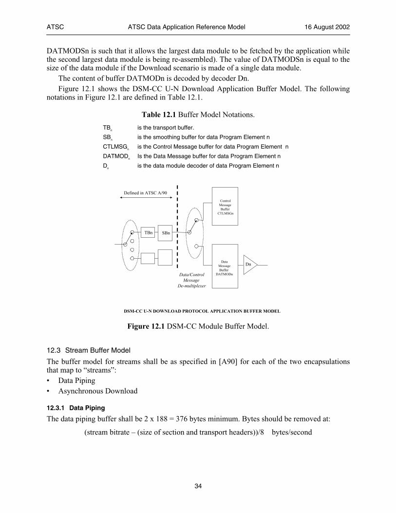
ATSC ATSC Data Application Reference Model 16 August 2002
34
DATMODSn is such that it allows the largest data module to be fetched by the application while the second largest data module is being re-assembled). The value of DATMODSn is equal to the size of the data module if the Download scenario is made of a single data module.
The content of buffer DATMODn is decoded by decoder Dn. Figure 12.1 shows the DSM-CC U-N Download Application Buffer Model. The following
notations in Figure 12.1 are defined in Table 12.1.
Table 12.1 Buffer Model Notations.
TBn is the transport buffer.
SBn is the smoothing buffer for data Program Element n
CTLMSGn is the Control Message buffer for data Program Element n
DATMODn Is the Data Message buffer for data Program Element n
Dn is the data module decoder of data Program Element n
TBn SBn
ControlMessage Buffer
CTLMSGn
DSM-CC U-N DOWNLOAD PROTOCOL APPLICATION BUFFER MODEL
Defined in ATSC A/90
Data/ControlMessage
De-multiplexer
DataMessageBuffer
DATMODn
Dn
Figure 12.1 DSM-CC Module Buffer Model.
12.3 Stream Buffer Model
The buffer model for streams shall be as specified in [A90] for each of the two encapsulations that map to “streams”: • Data Piping • Asynchronous Download
12.3.1 Data Piping
The data piping buffer shall be 2 x 188 = 376 bytes minimum. Bytes should be removed at:
(stream bitrate – (size of section and transport headers))/8 bytes/second
ATSC ATSC Data Application Reference Model 16 August 2002
35
12.3.2 Asynchronous Download
The asynchronous download section buffer shall be 2 x 4096 = 8192 bytes minimum. Bytes should be removed at:
(stream bitrate – (size of section and transport headers))/8 bytes/second
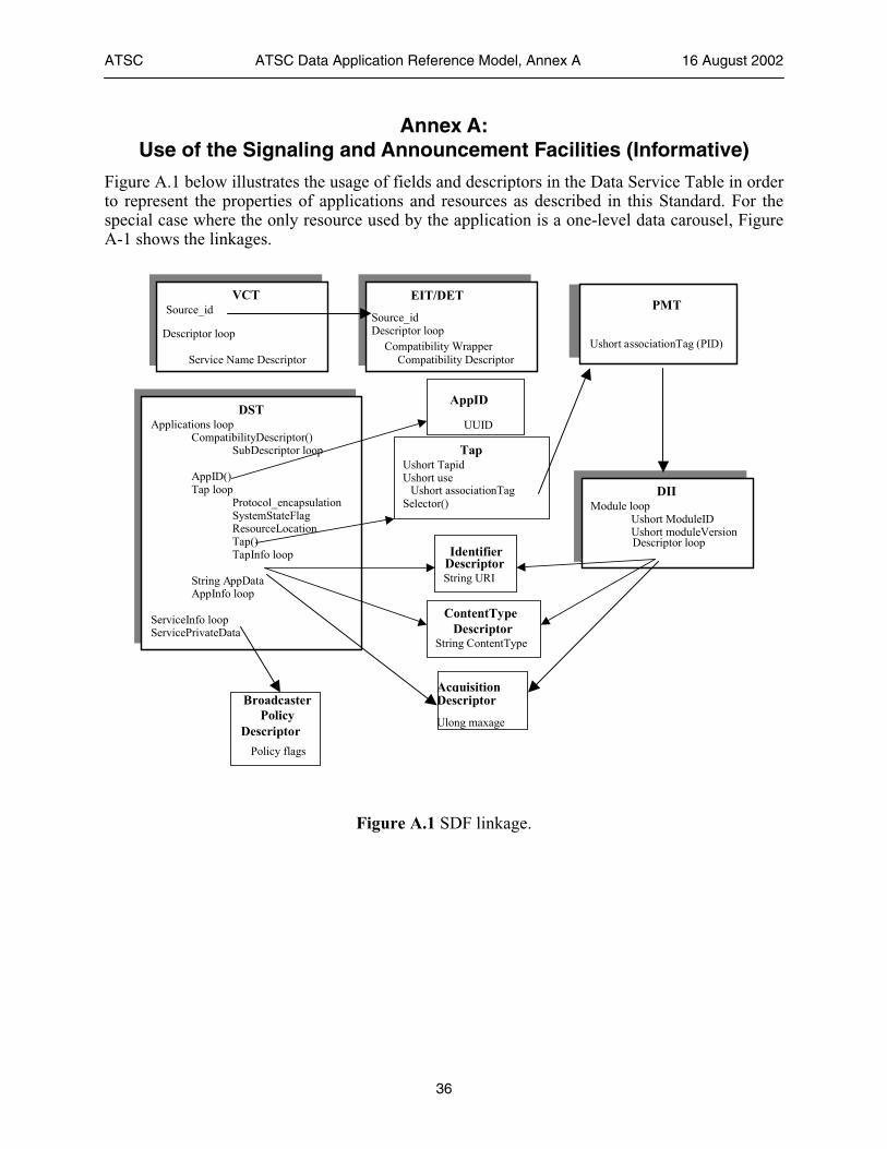
ATSC ATSC Data Application Reference Model, Annex A 16 August 2002
36
Annex A: Use of the Signaling and Announcement Facilities (Informative)
Figure A.1 below illustrates the usage of fields and descriptors in the Data Service Table in order to represent the properties of applications and resources as described in this Standard. For the special case where the only resource used by the application is a one-level data carousel, Figure A-1 shows the linkages.
DST Applications loop
CompatibilityDescriptor() SubDescriptor loop
AppID() Tap loop
Protocol_encapsulation SystemStateFlag ResourceLocation Tap() TapInfo loop
String A ppData AppInfo loop
ServiceInfo loop ServicePrivateData
AppID
UUID
TapUshort TapidUshort use
Selector()
IdentifierDescriptorString URI
ContentTypeDescriptor
String ContentType
Broadcaster Policy
Descriptor Policy flags
DII Module loop
Ushort ModuleIDUshort moduleVersionDescriptor loop
AcquisitionDescriptor
Ulong maxage
PMT
Ushort associationTag (PID)
VCT Source_id
Service Name Descriptor
Descriptor loop
EIT/DET
Compatibility WrapperCompatibility Descriptor
Descriptor loopSource_id
Ushort associationTag
Figure A.1 SDF linkage.
ATSC ATSC Data Application Reference Model, Annex B 16 August 2002
37
Annex B: Receiver Tuning Operations (Informative)
The announcement of data events in a DET or EIT serves mainly to attract the attention of a viewer when browsing the interactive program guide. However, the event start time serves to indicate when receivers should prepare to receive SDF information. SDF is a collection of two tables, the Data Service Table (DST) and the Network Resources Table (NRT). The first one will be used for early broadcast applications while the second one will become important once return channel technology is enabled.
When a viewer tunes to a Virtual Channel, a receiver should first attempt to find if data components exist in the channel. A receiver should examine the PMT to see if an SDF stream is available (recognizable by a stream_type value of 0x95). If this is the case, then the receiver should extract the DST and its list of applications. If one of the applications is a kind that it can decode (recognizable by an app_id_description value of 0x0000), then the receiver should determine (using the DST) the PID values of packets carrying application resources.
Several PID values may need to be tracked concurrently. One of them will signal the boot resources (recognizable by an action_type value of 0x01 in the DST) and a receiver should wait for boot data to appear. Before the boot data appears, receiver may (or may not) cache other resources described by the DST. Once the boot data arrives, receivers should execute this data as quickly as possible. When the application is running, some resources may have been cached and some may be available in broadcast carousels.
When a viewer switches to a different channel, a receiver may delete all information of the data service, or they may cache some resources in case the viewer switches back to the original channel.
ATSC ATSC Data Application Reference Model, Annex C 16 August 2002
38
Annex C: URI Resolution Procedures (Informative)
Some guidance is required on the resolution of URI’s by the receiver. A receiver in general can not determine the type of item identified by an arbitrary lid: URI from inspecting the URI alone. A receiver must examine the actual mapping information in the transport in order to make this determination.
It is assumed that the receiver is acquiring and decoding all tables required by A/65 and A/90, specifically including the VCT and DST, as well as all DII messages for the Data Service that is currently signaling the application making the request. The identifiers (URI's) that are labeling the various supported content types should be cached by the receiver. The receiver should maintain a table of all received identifiers along with either a transport-specific location information (as defined in [TSFS]), or a pointer to its internal representation of the resource.
When the application environment is asked to resolve a URI, these tables are searched for a string match, and suitable application environment dependent reference(s) returned to the requestor. In the case of a tv: URI, it should focus on the strings from Service Name descriptors it found in the VCT of the Virtual Channel containing the Data Service. In the case of a lid: URI, it should focus on the strings from URI descriptors it found in the DST and the DII messages of all data resources for the Data Service.
If the string fails to match in the case of a tv: URI, then the receiver should expand the search to all Virtual Channels in this transport.
If the string still fails to match in the case of a tv: URI, then the receiver should expand the search to Virtual Channels in other transport streams that it can receive in an attempt to exhaustively ensure the resource is not available. Note that this last step may take a significant amount of time, and receivers should cache all the Service Name descriptor information from all Virtual Channels in all transport streams that it can receive, if possible.
A match should always be found for the string in the case of a lid: URI, since any resource for the Data Service that is outside the Virtual Channel containing the Data Service should be listed in the NRT and referenced through the DST.
When matching the component name query strings for the “video/mpeg” content types (Section 7.3), the receiver needs to inspect all the elements of the multiple string structure of the component name descriptor. A match is found if ANY element matches. The search may not return more than one Program Element as Amendment 2A to [A65] constrains the strings to being unique within a Virtual Channel.
ATSC ATSC Data Application Reference Model, Annex D 16 August 2002
39
Annex D: Application Environment (Informative)
1. APPLICATION ENVIRONMENT MODEL
An application environment needs to provide certain capabilities that are required in order to decode, present, and interact with an application. This standard defines a model for this environment by means of defining certain capabilities that are expected to be supported by the environment. Specifically, this includes a state model and an implied data flow interconnectivity. A block diagram of the data flow in such a receiver model is shown in Figure D.1.
This figure is not meant to describe an actual implementation, but rather to communicate the interconnections and data flows required to properly design such a receiver.
The gray blocks are not covered by this standard and are included for clarity only. The clear blocks are described briefly below and described in more detail in the following sections.
The state model of Section 6 controls how the application environment is required to react to changes in the transport stream. This is not a complete state model for the application environment, but one that the environment is expected to build on.
The application buffer model of Section 12 is a description of the data models that are supported by this foundation and their respective buffer models for delivering the data to the application environment. Each data model supported is discussed.
The display model is the model that the environment must be designed to for output of graphics and on screen display (OSD) information
1.1 Display Model
An application environment is expected to support real-time decoding and presentation of streaming video content in accordance with [A53], and to mix the OSD with the video in the receiver.
The graphics capabilities of the application environment required to support this merged presentation with the video consists of an on-screen display (OSD) according to a minimum 640x480 resolution. The OSD must be capable of supporting the true color model (independent of how it is physically implemented).
The minimum color requirements of [ATVCC], [DTVCC], W3C, JavaTV and the common “color cube” are called to the attention of application environment implementers.
1.2 Audio Model
An application environment is expected to support real-time decoding and presentation of streaming audio content in accordance with [A53], mixed with the audio output of the environment.
1.3 Viewer Input
An application environment supports viewer interaction with graphics content and the audio. The viewer input capabilities of the application environment required to support this interaction minimally consist of a navigation device that permits the viewer to enter the following: • Move left, right, up, down • Digits zero through nine
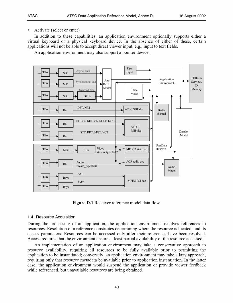
ATSC ATSC Data Application Reference Model, Annex D 16 August 2002
40
• Activate (select or enter) In addition to these capabilities, an application environment optionally supports either a
virtual keyboard or a physical keyboard device. In the absence of either of these, certain applications will not be able to accept direct viewer input; e.g., input to text fields.
An application environment may also support a pointer device.
Platform Services,
IO, Memory
MPEG2 video dec
AC3 audio dec
MPEG PSI dec
ATSC PSIP dec
ATSC SDF dec
TBn
TBn
TBn
TBn
TBn
Bn
MBn
Bn
Bsys
Bn
TBn
SBnTBn
Bn
TBn SBn
EBn
DEBn
SBn
DisplayModel
Async. data
Synchronous data
Sync’ed data
STT, RRT, MGT, VCT
EIT-k’s, DET-k’s, ETT-k, LTST
TBn
TBn Bsys
PAT
PMT
DST, NRT
Audiostream_type 0x81
Videostream_type 0x02
AppBufferModel
ApplicationEnvironment.
User Input
Audio Model
Back-channel
StateModel
UserData DTVCC
Figure D.1 Receiver reference model data flow.
1.4 Resource Acquisition
During the processing of an application, the application environment resolves references to resources. Resolution of a reference constitutes determining where the resource is located, and its access parameters. Resources can be accessed only after their references have been resolved. Access requires that the environment ensure at least partial availability of the resource accessed.
An implementation of an application environment may take a conservative approach to resource availability, requiring all resources to be fully available prior to permitting the application to be instantiated; conversely, an application environment may take a lazy approach, requiring only that resource metadata be available prior to application instantiation. In the latter case, the application environment would suspend the application or provide viewer feedback while referenced, but unavailable resources are being obtained.
ATSC ATSC Data Application Reference Model, Annex D 16 August 2002
41
Application resources may be either fully or partially cached, and thus available for an undetermined period of time; and there are no normative minimum or maximum retention time periods.
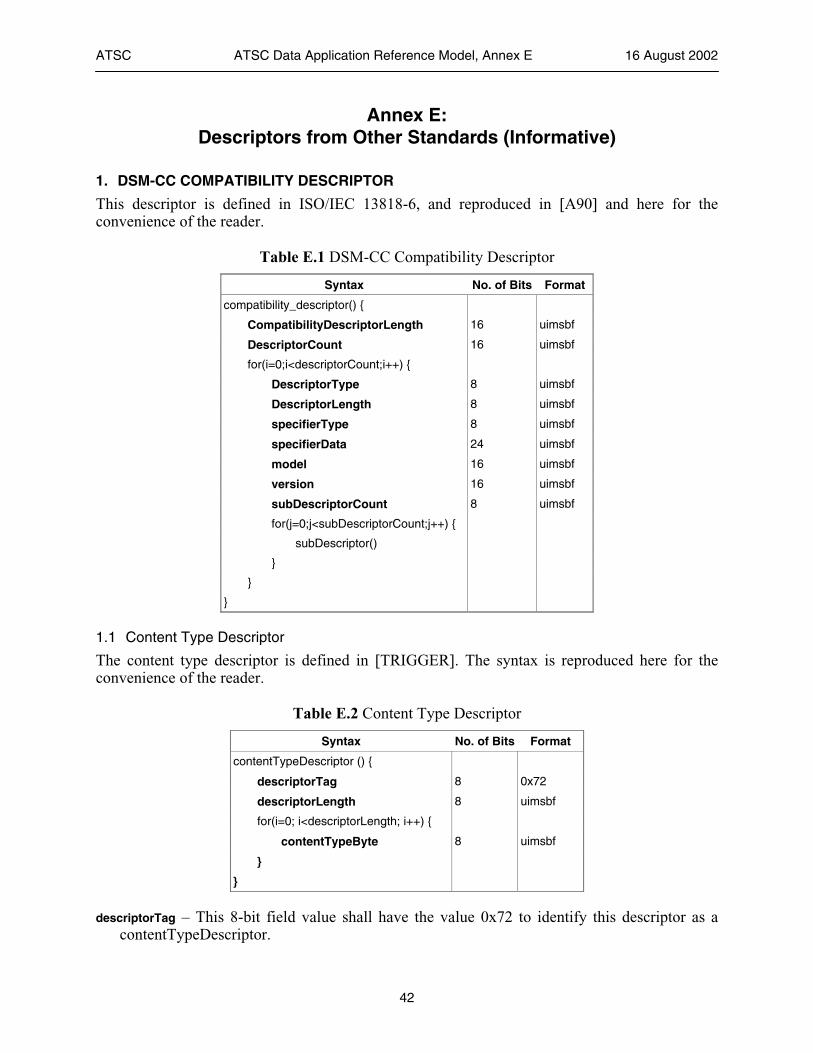
ATSC ATSC Data Application Reference Model, Annex E 16 August 2002
42
Annex E: Descriptors from Other Standards (Informative)
1. DSM-CC COMPATIBILITY DESCRIPTOR
This descriptor is defined in ISO/IEC 13818-6, and reproduced in [A90] and here for the convenience of the reader.
Table E.1 DSM-CC Compatibility Descriptor
Syntax No. of Bits Format
compatibility_descriptor() {
CompatibilityDescriptorLength 16 uimsbf
DescriptorCount 16 uimsbf
for(i=0;i<descriptorCount;i++) {
DescriptorType 8 uimsbf
DescriptorLength 8 uimsbf
specifierType 8 uimsbf
specifierData 24 uimsbf
model 16 uimsbf
version 16 uimsbf
subDescriptorCount 8 uimsbf
for(j=0;j<subDescriptorCount;j++) {
subDescriptor()
}
}
}
1.1 Content Type Descriptor
The content type descriptor is defined in [TRIGGER]. The syntax is reproduced here for the convenience of the reader.
Table E.2 Content Type Descriptor
Syntax No. of Bits Format
contentTypeDescriptor () {
descriptorTag 8 0x72
descriptorLength 8 uimsbf
for(i=0; i<descriptorLength; i++) {
contentTypeByte 8 uimsbf
}
}
descriptorTag – This 8-bit field value shall have the value 0x72 to identify this descriptor as a contentTypeDescriptor.
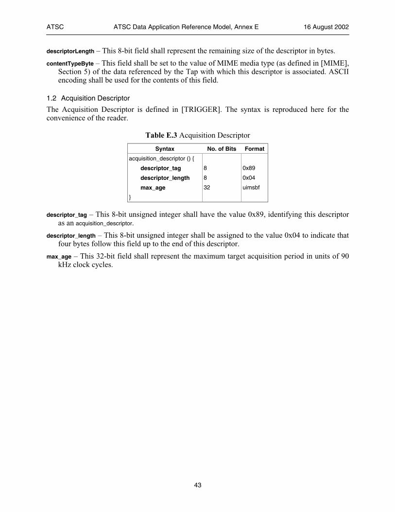
ATSC ATSC Data Application Reference Model, Annex E 16 August 2002
43
descriptorLength – This 8-bit field shall represent the remaining size of the descriptor in bytes.
contentTypeByte – This field shall be set to the value of MIME media type (as defined in [MIME], Section 5) of the data referenced by the Tap with which this descriptor is associated. ASCII encoding shall be used for the contents of this field.
1.2 Acquisition Descriptor
The Acquisition Descriptor is defined in [TRIGGER]. The syntax is reproduced here for the convenience of the reader.
Table E.3 Acquisition Descriptor
Syntax No. of Bits Format
acquisition_descriptor () {
descriptor_tag 8 0x89
descriptor_length 8 0x04
max_age 32 uimsbf
}
descriptor_tag – This 8-bit unsigned integer shall have the value 0x89, identifying this descriptor as an acquisition_descriptor.
descriptor_length – This 8-bit unsigned integer shall be assigned to the value 0x04 to indicate that four bytes follow this field up to the end of this descriptor.
max_age – This 32-bit field shall represent the maximum target acquisition period in units of 90 kHz clock cycles.