atsc digital television standard: part 4 – mpeg-2 video ... · atsc digital television standard:...
TRANSCRIPT

Advanced Television Systems Committee, Inc.1776 K Street, N.W., Suite 200
Washington, D.C. 20006
ATSC Digital Television Standard:Part 4 – MPEG-2 Video System Characteristics
Document A/53 Part 4:2009, 7 August 2009

Advanced Television Systems Committee Document A/53 Part 4:2009
The Advanced Television Systems Committee, Inc., is an international, non-profit organizationdeveloping voluntary standards for digital television. The ATSC member organizations representthe broadcast, broadcast equipment, motion picture, consumer electronics, computer, cable,satellite, and semiconductor industries.
Specifically, ATSC is working to coordinate television standards among differentcommunications media focusing on digital television, interactive systems, and broadbandmultimedia communications. ATSC is also developing digital television implementationstrategies and presenting educational seminars on the ATSC standards.
ATSC was formed in 1982 by the member organizations of the Joint Committee onInterSociety Coordination (JCIC): the Electronic Industries Association (EIA), the Institute ofElectrical and Electronic Engineers (IEEE), the National Association of Broadcasters (NAB), theNational Cable Telecommunications Association (NCTA), and the Society of Motion Picture andTelevision Engineers (SMPTE). Currently, there are approximately 140 members representing thebroadcast, broadcast equipment, motion picture, consumer electronics, computer, cable, satellite,and semiconductor industries.
ATSC Digital TV Standards include digital high definition television (HDTV), standarddefinition television (SDTV), data broadcasting, multichannel surround-sound audio, and satellitedirect-to-home broadcasting. Contact information is given below.
The revision history of this document is given below.
Mailing address Advanced Television Systems Commmittee, Inc.1776 K Street, N.W., Suite 1200Washington, D.C. 20006
Telephone 202-872-9160 (voice), 202-872-9161 (fax)
Web site http://www.atsc.org, E-mail: [email protected]
NOTE: The user's attention is called to the possibility that compliance with this standard mayrequire use of an invention covered by patent rights. By publication of this standard, no positionis taken with respect to the validity of this claim or of any patent rights in connection therewith.One or more patent holders have, however, filed a statement regarding the terms on which suchpatent holder(s) may be willing to grant a license under these rights to individuals or entitiesdesiring to obtain such a license. Details may be obtained from the ATSC Secretary and thepatent holder.
A/53 Part 4 Revision History
A/53 Part 4:2007 approved 3 January 2007
Amendment No. 1 approved 24 December 2007
A/53 Part 4:2009 approved 7 August 2009
Editorial correction to reference [17] 23 August 2011
2

MPEG-2 Video System Characteristics, Table of Contents 7 August 2009
Table of Contents
1. SCOPE 5
2. REFERENCES 5
2.1 Normative References 52.2 Informative References 6
3. COMPLIANCE NOTATION 6
3.1 Treatment of Syntactic Elements 63.2 Symbols, Abbreviations, and Mathematical Operators 6
4. SYSTEM OVERVIEW (INFORMATIVE) 7
5. POSSIBLE VIDEO INPUTS 8
6. SOURCE CODING SPECIFICATION 8
6.1 Constraints with Respect to ISO/IEC 13818-2 Main Profile 96.1.1 Sequence Header Constraints 96.1.2 Compression Format Constraints 96.1.3 Sequence Extension Constraints 106.1.4 Sequence Display Extension Constraints 106.1.5 Picture Header Constraints 106.1.6 Picture Coding Constraints 11
6.2 Bit Stream Specifications Beyond MPEG-2 116.2.1 Picture Extension and User Data Syntax 116.2.2 Picture User Data Syntax 116.2.3 ATSC Picture User Data Semantics 12
6.2.3.1 Captioning Data 136.2.3.2 Bar Data 13
6.2.3.2.1 Recommended Receiver Response to Bar Data 156.2.4 Active Format Description Data 15
6.2.4.1 AFD Syntax 156.2.4.2 AFD Semantics 166.2.4.3 Recommended Receiver Response to AFD 17
6.2.5 Relationship Between Bar Data and AFD (Informative) 17
3

Advanced Television Systems Committee Document A/53 Part 4:2009
Index of Tables and Figures
Table 5.1 Standardized Video Input Formats 8Table 6.1 Sequence Header Constraints 9Table 6.2 Compression Format Constraints 9Table 6.3 Sequence Extension Constraints 10Table 6.4 Sequence Display Extension Constraints 10Table 6.5 Picture Extension and User Data Syntax (Informative) 11Table 6.6 Picture User Data Syntax 11Table 6.7 user_data_identifier Value Assignments 12Table 6.8 ATSC_user_data Syntax 12Table 6.9 user_data_type_code Value Assignments 12Table 6.10 Captioning Data Syntax 13Table 6.12 Line Number Designation 14Table 6.11 Bar Data Syntax 14Table 6.13 Active Format Description Syntax 16Table 6.14 Active Format 17
Figure 4.1 ITU-R digital terrestrial television broadcasting model. 7Figure 4.2 High level view of encoding equipment. 8
4

ATSC Digital Television Standard:Part 4 – MPEG-2 Video System Characteristics
1. SCOPE
This Part describes the characteristics of the video subsystem of the Digital Television Standard.The input formats and bit stream characteristics are described in separate sections.
2. REFERENCES
At the time of publication, the editions indicated were valid. All standards are subject to revision,and parties to agreement based on this standard are encouraged to investigate the possibility ofapplying the most recent editions of the documents listed below.
2.1 Normative References
The following documents contain provisions which, through reference in this text, constituteprovisions of this standard.
[1] CEA: “Digital Television (DTV) Closed Captioning,” Doc. CEA-708-D, ConsumerElectronics Association, Arlington, VA, August 2008.
[2] ISO: “ISO/IEC IS 13818-1:2000 (E), International Standard, Information technology –Generic coding of moving pictures and associated audio information: systems.”
[3] ISO: “ISO/IEC IS 13818-2:2000 (E), International Standard, Information technology –Generic coding of moving pictures and associated audio information: video.”
[4] SMPTE: “Standard for Television—Component Video Signal 4:2:2, Bit-Parallel DigitalInterface,” Doc. SMPTE 125M (1995), Society of Motion Picture and Television Engineers,White Plains, N.Y., 1995.
[5] SMPTE: “Standard for Television—Composite Analog Video Signal, NTSC for StudioApplications,” Doc. SMPTE 170M (2004), Society of Motion Picture and TelevisionEngineers, White Plains, N.Y., 2004.
[6] SMPTE: “Standard for Television—Bit-Parallel Digital Interface, Component Video Signal4:2:2 16 x 9 Aspect Ratio,” Doc. SMPTE 267M (1995), Society of Motion Picture andTelevision Engineers, White Plains, N.Y., 1995.
[7] SMPTE: “Standard for Television—1920 x 1080 Scanning and Analog and Parallel DigitalInterfaces for Multiple Picture Rates,” Doc. SMPTE 274M (2005), Society of MotionPicture and Television Engineers, White Plains, N.Y., 2005.
[8] SMPTE: “Standard for Television—720 x 483 Active Line at 59.94-Hz Progressive ScanProduction, Digital Representation,” Doc. SMPTE 293M (2003), Society of Motion Pictureand Television Engineers, White Plains, N.Y., 2003.
[9] SMPTE: “Standard for Television—1280 x 720 Progressive Image Sample Structure,Analog and Digital Representation and Analog Interface,” Doc. SMPTE 296M (2001),Society of Motion Picture and Television Engineers, White Plains, N.Y., 2001.
Page 5

Advanced Television Systems Committee Document A/53 Part 4:2009
[10] ETSI: “Digital Video Broadcasting (DVB): Implementation Guidelines for the use ofMPEG-2 Systems, Video and Audio in Satellite, Cable and Terrestrial BroadcastingApplications,” Doc. ETSI TS 101 154 V1.7.1, Annex B, June 2005.
2.2 Informative References
[11] Digital TV Group: “Digital Receiver Implementation Guidelines and RecommendedReceiver Reaction to Aspect Ratio Signaling in Digital Video Broadcasting,” Issue 1.2.1,February 2001.
[12] ITU: “Encoding Parameters of Digital Television for Studios,” Doc. ITU-R BT.601-5(1994).
[13] ITU: “Parameter values for the HDTV Standards for Production and InternationalProgramme Exchange,” Doc. ITU-R BT. 709-5 (2002).
[14] SCTE: “Standard for Carriage of NTSC VBI Data in Cable Digital Transport Streams,” Doc.ANSI/SCTE 21 2001R2006, Society of Cable Telecommunications Engineers, Exton, PA,2006.
[15] CEA: “Active Format Description (AFD) & Bar Data Recommended Practice,” Doc. CEA-CEB16, Consumer Electronics Association, Arlington, VA, 31 July 2006.
[16] SMPTE: “Standard for Television—Format for Active Format Description and Bar Data,”Doc. SMPTE 2016-1 (2007), Society of Motion Picture and Television Engineers, WhitePlains, N.Y.
[17] ATSC: “Digital Television Standard, Part 1 – Digital Television System,” Doc. A/53, Part1:2009, Advanced Television Systems Committee, Washington, D.C., 7 August 2009.
[18] SMPTE Registration Authority: http://www.smpte-ra.org/mpegreg/mpegreg.html
3. COMPLIANCE NOTATION
As used in this document, “shall” denotes a mandatory provision of the standard. “Should”denotes a provision that is recommended but not mandatory. “May” denotes a feature whosepresence does not preclude compliance, that may or may not be present at the option of theimplementor.
3.1 Treatment of Syntactic Elements
This document contains symbolic references to syntactic elements used in the audio, video, andtransport coding subsystems. These references are typographically distinguished by the use of adifferent font (e.g., restricted), may contain the underscore character (e.g., sequence_end_code) andmay consist of character strings that are not English words (e.g., dynrng).
3.2 Symbols, Abbreviations, and Mathematical Operators
The symbols, abbreviations, and mathematical operators used herein are as found in Section 3.4of ATSC A/53 Part 1 [17].
one_bits – Each bit in fields marked, one_bits, shall be set to ‘1’.
6

MPEG-2 Video System Characteristics 7 August 2009
4. SYSTEM OVERVIEW (INFORMATIVE)
A basic block diagram representation of the system is shown in Figure 4.1. According to thismodel, the digital television system can be seen to consist of three subsystems.
• Source coding and compression• Service multiplex and transport• RF/transmissionFigure 4.2 illustrates a high level view of the encoding equipment. This view is not intended to
be representative of actual implementations, but is used to illustrate the relationship of variousclock frequencies within the encoder.
The source coding domain, represented schematically by the video, audio, and transportencoders, uses a family of frequencies which are based on a 27 MHz clock (f27MHz). This clock isused to generate a 42-bit sample of the frequency which is partitioned into two parts defined bythe MPEG-2 specification. These are the 33-bit program_clock_reference_base and the 9-bitprogram_clock_reference_extension. The former is equivalent to a sample of a 90 kHz clock which islocked in frequency to the 27 MHz clock, and is used by the audio and video source encoderswhen encoding the presentation time stamp (PTS) and the decode time stamp (DTS). The audio andvideo sampling clocks, fa and fv respectively, are frequency-locked to the 27 MHz clock. This canbe expressed as the requirement that there exist two pairs of integers, (na, ma) and (nv, mv), suchthat
Video Source Codingand Compression
Video
Video Subsystem
Audio Source Codingand Compression
Audio
Audio Subsystem
Service Multiplex
Transport
Ancillary Data
Control Data
Modulation
ChannelCoding
Receiver Characteristics
Service Multiplex and Transport RF/Transmission System
Figure 4.1 ITU-R digital terrestrial television broadcasting model.
7

Advanced Television Systems Committee Document A/53 Part 4:2009
and
5. POSSIBLE VIDEO INPUTS
While not required by this standard, there are certain television production standards, shown inTable 5.1, that define video formats that relate to compression formats specified by this standard.
The compression formats may be derived from one or more appropriate video input formats. Itmay be anticipated that additional video production standards will be developed in the future thatextend the number of possible input formats.
6. SOURCE CODING SPECIFICATION
The DTV video compression algorithm shall conform to the Main Profile syntax of ISO/IEC13818-2 [3]. The allowable parameters shall be bounded by the upper limits specified for the
Table 5.1 Standardized Video Input Formats
Video Standard Active Lines Active Samples/ LineSMPTE 274M [7] 1080 1920SMPTE 296M [9] 720 1280ITU-R BT.601-5 [12] 483 720
fa
na
ma
------ 27 MHz=
fv
nv
mv
------ 27 MHz=
Program ClockReference
VideoEncoder
AudioEncoder
FrequencyDividerNetwork
A/D
A/D
VSBModulator
FEC andSyncInsertion
AdaptationHeaderEncoder
TransportEncoder
Video In
Audio In
program_clock_reference_base
program_clock_reference_extension
33 9
fv fa
fTP fsym
f27 MHz
RF Out
Figure 4.2 High level view of encoding equipment.
8

MPEG-2 Video System Characteristics 7 August 2009
Main Profile at High Level.1 Additionally, all bit streams shall meet the constraints andspecifications described in Sections 6.1 and 6.2.
6.1 Constraints with Respect to ISO/IEC 13818-2 Main Profile
The following tables list the allowed values for each of the ISO/IEC 13818-2 [3] syntacticelements which are restricted beyond the limits imposed by MP@HL.
In these tables conventional numbers denote decimal values, numbers preceded by 0x are to beinterpreted as hexadecimal values and numbers within single quotes (e.g., ‘10010100’) are to beinterpreted as a string of binary digits.
6.1.1 Sequence Header Constraints
Table 6.1 identifies parameters in the sequence header of a bit stream that shall be constrained bythe video subsystem and lists the allowed values for each.
The allowable values for the field bit_rate_value are application-dependent. In the primaryapplication of terrestrial broadcast, this field shall correspond to a bit rate which is less than orequal to 19.4 Mbps. In the high data rate mode, the corresponding bit rate is less than or equal to38.8 Mbps.
6.1.2 Compression Format Constraints
Table 6.2 lists the allowed compression formats.
1. See ISO/IEC 13818-2 [3] Section 8 for more information regarding profiles and levels.
Table 6.1 Sequence Header Constraints
Sequence Header Syntactic Element Allowed Valuehorizontal_size_value see Table 6.2vertical_size_value see Table 6.2aspect_ratio_information see Table 6.2frame_rate_code see Table 6.2bit_rate_value ( 19.4 Mbps) 48500bit_rate_value ( 38.8 Mbps) 97000vbv_buffer_size_value 488
Table 6.2 Compression Format Constraints
vertical_size_value horizontal_size_value aspect_ratio_information frame_rate_code progressive_sequence
1080a
a. Note that 1088 lines are actually coded in order to satisfy the MPEG-2 requirement that the coded vertical size bea multiple of 16 (progressive scan) or 32 (interlaced scan). The bottom 8 lines are black, per MPEG rules.
1920 1,3 1,2,4,5 ‘1’4,5 ‘0’
720 1280 1,3 1,2,4,5,7,8 ‘1’480 704 2,3 1,2,4,5,7,8 ‘1’
4,5 ‘0’640 1,2 1,2,4,5,7,8 ‘1’
4,5 ‘0’Legend for MPEG-2 coded values: aspect_ratio_information: 1 = square samples, 2 = 4:3 display aspect ratio, 3 = 16:9 display aspect ratio frame_rate_code: 1 = 23.976 Hz, 2 = 24 Hz, 4 = 29.97 Hz, 5 = 30 Hz, 7 = 59.94 Hz, 8 = 60 Hz progressive_sequence: ‘0’ = interlaced scan, ‘1’ = progressive scan
9

Advanced Television Systems Committee Document A/53 Part 4:2009
6.1.3 Sequence Extension Constraints
Table 6.3 identifies parameters in the sequence extension part of a bit stream that shall beconstrained by the video subsystem and lists the allowed values for each. A sequence_extension
structure is required to be present after every sequence_header structure.
Note: The profile_and_level_indication field shall indicate the lowest profile and leveldefined in ISO/IEC 13818-2 [3] Section 8 that is consistent with the parameters ofthe video elementary stream.
6.1.4 Sequence Display Extension Constraints
Table 6.4 identifies parameters in the sequence display extension part of a bit stream that shall beconstrained by the video subsystem and lists the allowed values for each.
The values for color_primaries, transfer_characteristics, and matrix_coefficients shall be explicitlyindicated in the sequence_display_extension. While all values for color_primaries, transfer_characteristics,and matrix_coefficients defined in Tables 6-7, 6-8, and 6-9 of ISO/IEC 13818-2 [3] are allowed in thetransmitted bit stream, it is noted that those of ITU-R BT.709 [13] and SMPTE 170M [5] are themost likely to be in common use.
Note: Some previously-encoded legacy material may not have the colorimetry (i.e.,color_primaries, transfer_characteristics, and matrix_coefficients) explicitly indicated in thesequence_display_extension, in which case the colorimetry is most likely ITU-RBT.709 [13] for all formats except those formats with vertical_size_value = 480,which are most likely to have colorimetry according to SMPTE 170M [5].
6.1.5 Picture Header Constraints
In all cases other than when vbv_delay has the value 0xFFFF, the value of vbv_delay shall beconstrained as follows:
vbv_delay 45000
Table 6.3 Sequence Extension Constraints
Sequence Extension Syntactic Element Allowed Valuesprogressive_sequence see Table 6.2profile_and_level_indication see Notechroma_format ‘01’horizontal_size_extension ‘00’vertical_size_extension ‘00’bit_rate_extension ‘0000 0000 0000’vbv_buffer_size_extension ‘0000 0000’frame_rate_extension_n ‘00’frame_rate_extension_d ‘0000 0’
Table 6.4 Sequence Display Extension Constraints
Sequence Display Extension Syntactic Element Allowed Valuesvideo_format ‘000’
10

MPEG-2 Video System Characteristics 7 August 2009
6.1.6 Picture Coding Constraints
The value frame_pred_frame_dct shall be ‘1’ if progressive_frame is ‘1’.
6.2 Bit Stream Specifications Beyond MPEG-2
This section covers the extension and user data part of the video syntax. The syntax used for theinsertion of closed captioning2, bar data and active format description in user data is described.“Picture user data” is used here to refer to user data inserted according to ISO/IEC 13818-2 [3],extension_and_userdata(2) structure placement as defined in ISO/IEC 13818-2, Section 6.2.2 [3],which follows the picture_header() and picture_coding_extension() structures.
6.2.1 Picture Extension and User Data Syntax
The picture user data shall be constructed per ISO/IEC 13818-2 Section 6.2.2.2 [3]. Table 6.5reproduces this syntax for the convenience of the reader, with the value ‘i’ replaced with the value‘2’ indicating the syntactic placement at the picture level (following picture_coding_extension().
Note: In accordance with the bit stream syntax in Table 6.5, more than one pictureuser data construct may follow any given picture header.
No more than one user_data() structure using the same user_data_type_code (see Table 6.8 andTable 6.9) shall be present following any given picture header.
6.2.2 Picture User Data Syntax
Table 6.6 describes the picture user data syntax that shall be used for the user_data() structurecarried in extension_and_user_data(2) of Section 6.2.2.2 of [3], reproduced for convenience in Table6.5.
2. Implementers should note that CEA-708 [1] describes the semantics for closed captions.
Table 6.5 Picture Extension and User Data Syntax (Informative)
Value No. of Bits Formatextension_and_user_data(2) {
while ((nextbits() == extension_start_code ) ||(nextbits() == user_data_start_code)) {if (nextbits() == extension_start_code)
extension_data(2)if (nextbits() == user_data_start_code)
user_data()}
}
Table 6.6 Picture User Data Syntax
Syntax No. of Bits Formatuser_data() {
user_data_start_code 32 bslbfuser_data_identifier 32 bslbfuser_structure()
}
11

Advanced Television Systems Committee Document A/53 Part 4:2009
Receiving devices are expected to silently discard any unrecognized video user dataencountered in the video bit stream. For example, if an unrecognized user_data_identifier is seenfollowing the user_data_start_code, the user data should be discarded until another start code prefix isseen.
6.2.3 ATSC Picture User Data Semantics
user_data_start_code – This shall be set to 0x0000 01B2, which is the value is established for userdata by ISO/IEC 13818-2 [3].
user_data_identifier – This is a 32 bit code that indicates the syntax and semantics of theuser_structure() according to Table 6.7. It should be set to a registered value of the format_identifier
as defined in ISO/IEC 13818-1 [2] and maintained by the SMPTE RA [18].
Note: Use of registered values, while not mandatory, is highly recommended asnon-registered values can lead to errors in receiver processing of privately-supplieduser_data() packets. The list of registered values is available at http://www.smpte-ra.org/mpegreg/mpegreg.html. Not all of these have application asuser_data_identifier values in this context.
user_structure() – This is a variable length data structure defined by the value of user_data_identifier
and shall be set according to Table 6.7.
user_data_type_code – This is an 8-bit value that identifies the type of ATSC user data to follow inthe user_data_type_structure() and shall be set according to Table 6.9.
Table 6.7 user_data_identifier Value Assignments
user_data_identifier value user_structure()0x47413934 (“GA94”) ATSC_user_data() (as defined in Table 6.8)0x44544731 (“DTG1”) afd_data() (as defined in Section 6.2.4)All other values Not defined in this Standard.
Table 6.8 ATSC_user_data Syntax
Syntax No. of Bits FormatATSC_user_data() {
user_data_type_code 8 uimsbfuser_data_type_structure()
}
Table 6.9 user_data_type_code Value Assignments
user_data_type_code value user_data_type_structure()0x00 – 0x02 ATSC Reserved0x03 MPEG_cc_data() (as defined in Table 6.10)0x04 – 0x05 ATSC Reserved0x06 bar_data() (as defined in Section 6.2.3.2)0x07 – 0xFF ATSC Reserved
12

MPEG-2 Video System Characteristics 7 August 2009
6.2.3.1 Captioning Data
Table 6.10 describes the syntax of captioning data.
cc_data() shall be as defined in CEA-708 [1], Table 2.
6.2.3.2 Bar Data
Table 6.11 describes the syntax of bar data. Bar data should be included in video user datawhenever the rectangular picture area containing useful information does not extend to the fullheight or width of the coded frame3 and AFD alone is insufficient to describe the extent of theimage. See Section 6.2.4.
When present, bar data shall be carried in the data structure bar_data(), within the picture userdata syntax as shown in Table 6.6. After any sequence_header() such bar data shall appear before thenext picture_data() within extension_and_user_data(2). After introduction, such bar data shall remain ineffect until:
1) the next sequence_header(), or
2) extension_and_user_data(2) containing a bar_data() structure which contains new bar data, or
3) extension_and_user_data(2) containing AFD per Section 6.2.4.
After any sequence_header(), unless AFD data is present specifying otherwise, the absence ofbar data shall indicate that the rectangular picture area containing useful information extends tothe full height and width of the coded frame.
Bar data is constrained (below) to be signalled in pairs, either top and bottom bars or left andright bars, but not both pairs at once. Bars may be unequal in size. One bar of a pair may be zerowidth or height.
Table 6.10 Captioning Data Syntax
Syntax No. of Bits FormatMPEG_cc_data() {
cc_data()marker_bits 8 ‘1111 1111’
}
3. In other words, the video is letterboxed (bars above and/or below video) or pillarboxed (bars left and/or right ofvideo).
13

Advanced Television Systems Committee Document A/53 Part 4:2009
Designation of line numbers for line_number_end_of_top_bar and line_number_start_of_bottom_bar isvideo format-dependent and shall conform to the applicable standard indicated in Table 6.12.
Note: The range of line numbers and pixels within the coded frame for each imageformat is specified in Table 2 of SMPTE 2016-1 [17].
top_bar_flag – This flag shall indicate, when set to ‘1’, that the top bar data is present. If left_bar_flag
is ‘1’, this flag shall be set to ‘0’.
bottom_bar_flag – This flag shall indicate, when set to ‘1’, that the bottom bar data is present. Thisflag shall have the same value as top_bar_flag.
left_bar_flag – This flag shall indicate, when set to ‘1’, that the left bar data is present. If top_bar_flag
is ‘1’, this flag shall be set to ‘0’.
right_bar_flag – This flag shall indicate, when set to ‘1’, that the right bar data is present. This flagshall have the same value as left_bar_flag.
Table 6.11 Bar Data Syntax
Syntax No. of Bits Formatbar_data() {
top_bar_flag 1 bslbfbottom_bar_flag 1 bslbfleft_bar_flag 1 bslbfright_bar_flag 1 bslbfreserved 4 ‘1111’if (top_bar_flag == ‘1’) {
one_bits 2 ‘11’line_number_end_of_top_bar 14 uimsbf
}if (bottom_bar_flag == ‘1’) {
one_bits 2 ‘11’line_number_start_of_bottom_bar 14 uimsbf
}if (left_bar_flag == ‘1’) {
one_bits 2 ‘11’pixel_number_end_of_left_bar 14 uimsbf
}if (right_bar_flag == ‘1’) {
one_bits 2 ‘11’pixel_number_start_of_right_bar 14 uimsbf
}}
Table 6.12 Line Number Designation
Video Format Applicable Standard480 Interlaced 4:3 SMPTE 125M [4]480 Interlaced 16:9 SMPTE 267M [6]480 Progressive SMPTE 293M [8]720 Progressive SMPTE 296M [9]1080 Interlaced SMPTE 274M [7]1080 Progressive SMPTE 274M [7]
14

MPEG-2 Video System Characteristics 7 August 2009
line_number_end_of_top_bar – A 14-bit unsigned integer value representing the last line of ahorizontal letterbox bar area at the top of the reconstructed frame. Designation of linenumbers shall be as defined per each applicable standard in Table 6.12.
line_number_start_of_bottom_bar – A 14-bit unsigned integer value representing the first line of ahorizontal letterbox bar area at the bottom of the reconstructed frame. Designation of linenumbers shall be as defined per each applicable standard in Table 6.12.
pixel_number_end_of_left_bar – A 14-bit unsigned integer value representing the last horizontalluminance sample of a vertical pillarbox bar area at the left side of the reconstructed frame.Pixels shall be numbered from zero, starting with the leftmost pixel.
pixel_number_start_of_right_bar – A 14-bit unsigned integer value representing the first horizontalluminance sample of a vertical pillarbox bar area at the right side of the reconstructed frame.Pixels shall be numbered from zero, starting with the leftmost pixel.
6.2.3.2.1 Recommended Receiver Response to Bar Data
Receiving device designers are strongly encouraged to study Consumer Electronics Association(CEA) bulletin CEB16 [16], which contains recommendations regarding the processing of bardata.
6.2.4 Active Format Description Data
Active Format Description (AFD) should be included in video user data whenever the rectangularpicture area containing useful information does not extend to the full height or width of the codedframe. AFD data may also be included in user data when the rectangular picture area containinguseful information extends to the full height and width of the coded frame.
When present, the AFD shall be carried using the syntax defined in [10], inextension_and_user_data(2) in the MPEG-2 video Elementary Stream. After any sequence_header() thedefault aspect ratio of the area of interest shall be that signaled by the parameters in thesequence_header() and sequence_display_extension() structures. After any sequence_header() the AFD,when present, shall appear before the next picture_data(). After introduction, such an AFD shallremain in effect until the next sequence_header() or until a new AFD is introduced.
Note: The AFD syntax as shown in Section 6.2.4.1, when combined with thestructures above to form the entire user data structure, is identical to that specifiedin ETSI TS 101 154 V1.7.1 [10], and is reprinted here with permission. Semanticsare documented in Section 6.2.4.2; some are intentionally different from those inETSI 101 154.
6.2.4.1 AFD Syntax
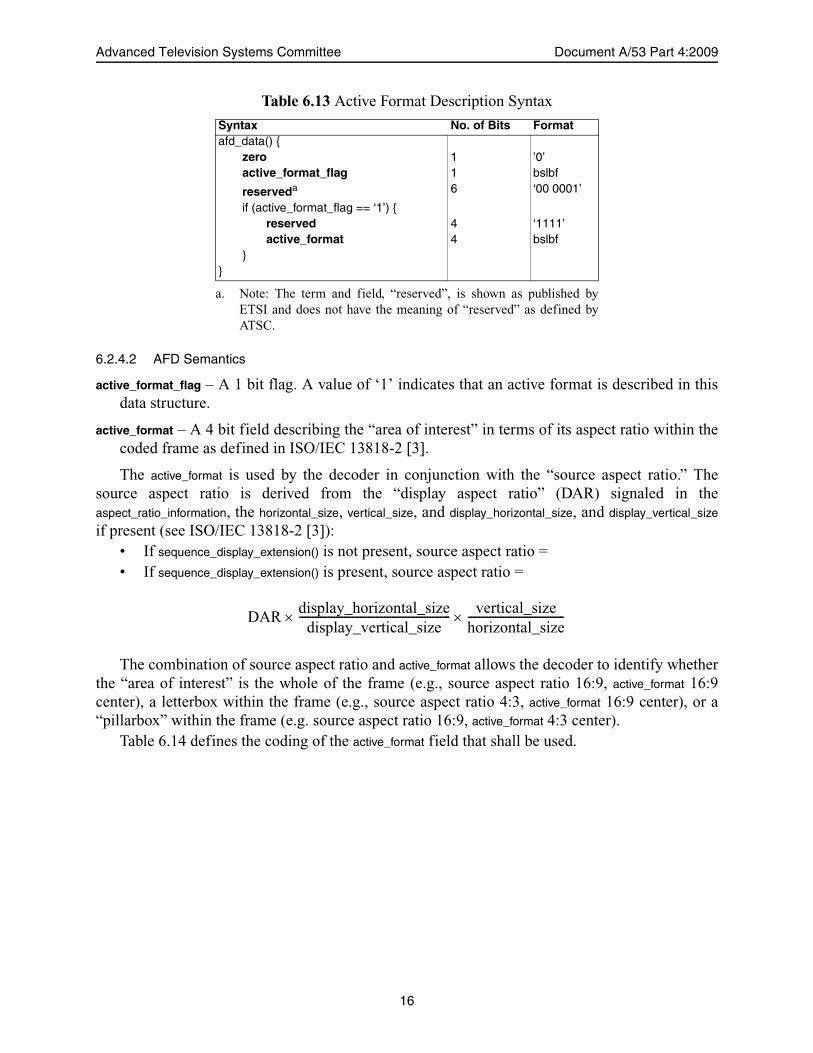
Table 6.13 shows the syntax defined in [10] which is provided for the convenience of the reader.
15
Advanced Television Systems Committee Document A/53 Part 4:2009
6.2.4.2 AFD Semantics
active_format_flag – A 1 bit flag. A value of ‘1’ indicates that an active format is described in thisdata structure.
active_format – A 4 bit field describing the “area of interest” in terms of its aspect ratio within thecoded frame as defined in ISO/IEC 13818-2 [3].
The active_format is used by the decoder in conjunction with the “source aspect ratio.” Thesource aspect ratio is derived from the “display aspect ratio” (DAR) signaled in theaspect_ratio_information, the horizontal_size, vertical_size, and display_horizontal_size, and display_vertical_size
if present (see ISO/IEC 13818-2 [3]):• If sequence_display_extension() is not present, source aspect ratio =• If sequence_display_extension() is present, source aspect ratio =
The combination of source aspect ratio and active_format allows the decoder to identify whetherthe “area of interest” is the whole of the frame (e.g., source aspect ratio 16:9, active_format 16:9center), a letterbox within the frame (e.g., source aspect ratio 4:3, active_format 16:9 center), or a“pillarbox” within the frame (e.g. source aspect ratio 16:9, active_format 4:3 center).
Table 6.14 defines the coding of the active_format field that shall be used.
Table 6.13 Active Format Description Syntax
Syntax No. of Bits Formatafd_data() {
zero 1 ’0’active_format_flag 1 bslbf
reserveda 6 ‘00 0001’
if (active_format_flag == ‘1’) {reserved 4 ‘1111’active_format 4 bslbf
}}
a. Note: The term and field, “reserved”, is shown as published byETSI and does not have the meaning of “reserved” as defined byATSC.
DARdisplay_horizontal_size
display_vertical_size--------------------------------------------------------- vertical_size
horizontal_size------------------------------------
16

MPEG-2 Video System Characteristics 7 August 2009
AFD ‘0000’ indicates that information is not available and is undefined. Unless bar data isavailable, DTV receivers and video equipment should interpret the active image area as being thesame as that of the coded frame.
AFD ‘0000’, when accompanied by bar data, signals that the image’s aspect ratio is narrowerthan 16:9, but is not either 4:3 or 14:9. The bar data should be used to determine the extent of theimage.
AFD ‘0100’, which should be accompanied by bar data, signals that the image’s aspect ratio iswider than 16:9, as is typically the case with widescreen features. The bar data should be used todetermine the height of the image.
Use of either ‘0010’ or ‘0011’ is not recommended in the ATSC television system. Values‘0001’, ‘0101’ through ‘0111’, and ‘1100’ are reserved.
6.2.4.3 Recommended Receiver Response to AFD
Receiving device designers are strongly encouraged to study Consumer Electronics Association(CEA) bulletin CEB16 [16], which contains recommendations regarding the processing of AFD.
6.2.5 Relationship Between Bar Data and AFD (Informative)
Certain combinations of Active Format Description and bar data may be present in video user data(either, neither, or both). Note that AFD data may not always exactly match bar data because AFDonly deals with 4:3, 14:9, and 16:9 aspect ratios while bar data can represent nearly any aspectratio. When AFD and bar data are present together, AFD should be used in preference to bar data,except in the cases of AFD ‘0000’ and ‘0100’, where bar data should be used in concert with AFDas described above.
Table 6.14 Active Format
active_format Description4:3 coded frames 16:9 coded frames
‘0000’ undefined (see below) undefined (see below)‘0001’ Reserved Reserved‘0010’ – ‘0011” Not recommended Not recommended0100 Aspect ratio greater than 16:9 (see below) Aspect ratio greater than 16:9 (see below)‘0101’ – ‘0111’ Reserved Reserved‘1000’ 4:3 full frame image 16:9 full frame image‘1001’ 4:3 full frame image 4:3 pillarbox image‘1010’ 16:9 letterbox image 16:9 full frame image‘1011’ 14:9 letterbox image 14:9 pillarbox image‘1100’ Reserved Reserved‘1101’ 4:3 full frame image, alternative 14:9 center 4:3 pillarbox image, alternative 14:9 center‘1110’ 16:9 letterbox image, alternative 14:9 center 16:9 full frame image, alternative 14:9 center‘1111’ 16:9 letterbox image, alternative 4:3 center 16:9 full frame image, alternative 4:3 center
17
