atsc data broadcast standard · atsc a/90:2013 atsc data broadcast standard 28 october 2013 2 the...
TRANSCRIPT
ATSC A/90:2013 ATSC Data Broadcast Standard 28 October 2013
1
ATSC Data Broadcast Standard
Doc. A/90:2013 28 October 2013
Advanced Television Systems Committee 1776 K Street, N.W. Washington, D.C. 20006 202-872-9160
ATSC A/90:2013 ATSC Data Broadcast Standard 28 October 2013
2
The Advanced Television Systems Committee, Inc., is an international, non-profit organization developing voluntary standards for digital television. The ATSC member organizations represent the broadcast, broadcast equipment, motion picture, consumer electronics, computer, cable, satellite, and semiconductor industries.
Specifically, ATSC is working to coordinate television standards among different communications media focusing on digital television, interactive systems, and broadband multimedia communications. ATSC is also developing digital television implementation strategies and presenting educational seminars on the ATSC standards.
ATSC was formed in 1982 by the member organizations of the Joint Committee on InterSociety Coordination (JCIC): the Electronic Industries Association (EIA), the Institute of Electrical and Electronic Engineers (IEEE), the National Association of Broadcasters (NAB), the National Cable Telecommunications Association (NCTA), and the Society of Motion Picture and Television Engineers (SMPTE). Currently, there are approximately 140 members representing the broadcast, broadcast equipment, motion picture, consumer electronics, computer, cable, satellite, and semiconductor industries.
ATSC Digital TV Standards include digital high definition television (HDTV), standard definition television (SDTV), data broadcasting, multichannel surround-sound audio, and satellite direct-to-home broadcasting.
Note: The user's attention is called to the possibility that compliance with this standard may require use of an invention covered by patent rights. By publication of this standard, no position is taken with respect to the validity of this claim or of any patent rights in connection therewith. One or more patent holders have, however, filed a statement regarding the terms on which such patent holder(s) may be willing to grant a license under these rights to individuals or entities desiring to obtain such a license. Details may be obtained from the ATSC Secretary and the patent holder.
Revision History Version Date Initial version of A/90 Standard approved 26 July 2000 Corrigendum No. 1 and Corrigendum No. 2 approved 1 April 2002 Amendment No. 1 approved 14 May 2002 A/90:2013 approved 28 October 2013
ATSC A/90:2013 ATSC Data Broadcast Standard 28 October 2013
3
Table of Contents 1. SCOPE .....................................................................................................................................................7
1.1 Introduction and Background 7 1.2 Organization 7
2. REFERENCES .........................................................................................................................................7 2.1 Normative References 7 2.2 Informative References 8
3. DEFINITION OF TERMS ..........................................................................................................................9 3.1 Compliance Notation 9 3.2 Treatment of Syntactic Elements 9
3.2.1 Reserved Elements 9 3.3 Acronyms and Abbreviation 9 3.4 Terms 11 3.5 Section and Data Structure Syntax Notation 14 3.6 Special Field Meanings 15 3.7 Code Points (Informative) 15
3.7.1 Table ID Values 15 3.7.2 Stream Type Values 15 3.7.3 Descriptor Tag Values 15 3.7.4 Table Types 16
4. SYSTEM OVERVIEW (INFORMATIVE) ................................................................................................. 16 4.1 Distribution, Local Diagram Assumptions 16 4.2 Receiver Diagram Assumptions 16
5. OVERVIEW OF THE DATA BROADCASTING MECHANISMS (INFORMATIVE) ................................ 17 5.1 Data Download Protocol 17 5.2 DSM-CC Addressable Sections 17 5.3 Asynchronous Data 17 5.4 Synchronous and Synchronized Streaming Data 17 5.5 Data Piping 18 5.6 Data Services 18
6. DSM-CC COMPATIBILITY DESCRIPTOR ............................................................................................ 18 6.1 Compatibility Descriptor Syntax 18 6.2 IEEE OUI Specifier 20
7. DATA DOWNLOAD PROTOCOL .......................................................................................................... 20 7.1 Introduction 20
7.1.1 Transmission of Streaming and Non-streaming Asynchronous Data 21 7.1.2 Transmission of Non-streaming, Synchronized Data 21 7.1.3 Structure of the Non-flow Controlled and Carousel Scenarios 22
7.2 Data Download Protocol Specification 25 7.2.1 DSM-CC Section Syntax for User-to-Network Download Protocol 25 7.2.2 DSM-CC Adaptation Header Syntax 27 7.2.3 Download Control Messages 28 7.2.4 Download Data Block Message Syntax 35
ATSC A/90:2013 ATSC Data Broadcast Standard 28 October 2013
4
8. DSM-CC ADDRESSABLE SECTION .................................................................................................... 36 8.1 Encapsulation Rules in DSM-CC Addressable Sections 38
9. SYNCHRONOUS AND SYNCHRONIZED STREAMING DATA ............................................................ 39 9.1 Synchronous Data Bitstream Syntax 39
9.1.1 Synchronous Data Header 40 9.1.2 Synchronous Data Sequence Structure 41
9.2 Synchronized Data Bitstream Syntax 41 9.2.1 Synchronized Data Packet Structure 41
9.3 Datagram Encapsulation 43 10. DATA PIPING ......................................................................................................................................... 43 11. DATA SERVICE ANNOUNCEMENT REQUIREMENTS ........................................................................ 43
11.1 Introduction 43 11.2 Virtual Channels 43 11.3 Data Event Table 44
11.3.1 DET Syntax 46 11.4 Extended Text Table 48 11.5 Data Service Descriptor 48 11.6 PID Count Descriptor 50 11.7 Announcement of Future Data Services 51
12. SERVICE DESCRIPTION FRAMEWORK .............................................................................................. 54 12.1 Association Tag Descriptor 54 12.2 Data Service Table 55
12.2.1 Data Service Table Bytes 56 12.2.2 Tap Structure 59 12.2.3 Download Descriptor 62 12.2.4 Multiprotocol Encapsulation Descriptor 63
12.3 Network Resources Table 64 12.3.1 Network Resources Table Bytes Structure 66 12.3.2 DSM-CC Resource Descriptor 66
13. SYSTEM TARGET DECODER MODEL ................................................................................................. 71 13.1 Smoothing Buffer Descriptor 71
13.1.1 Data Service Belonging to a Virtual Channel of service_type of 0x04 72 13.1.2 Data Service Belonging to a Virtual Channel of service_type of 0x02 or 0x03 72 13.1.3 Descriptors in the ES Information Descriptor Loop 72 13.1.4 Descriptors in the Extended Program Information Descriptor Loop 73 13.1.5 Buffering 73
13.2 Buffer Model for Synchronized Data Services 73 13.2.1 General Constraints 74 13.2.2 Data Elementary Stream Buffer for Synchronized Services 74 13.2.3 Minimum Elementary Stream Buffer Size 75 13.2.4 Buffer Sizes and Data Service Levels 75 13.2.5 Buffer Arrangement 75
14. DESCRIPTOR HIERARCHY AND SCOPE ............................................................................................ 76
ATSC A/90:2013 ATSC Data Broadcast Standard 28 October 2013
5
Index of Tables and Figures Table 6.1 DSM-CC Compatibility Descriptor 18 Table 6.2 Descriptor Type Field Values 19 Table 6.3 Specifier Type Field Values 19 Table 6.4 DSM-CC Compatibility Sub-Descriptor 20 Table 6.5 Specifier Data Definition Using IEEE OUI 20 Table 7.1 DSM-CC Section 26 Table 7.2 DSM-CC Adaptation Header 27 Table 7.3 DSM-CC Message Header 28 Table 7.4 Semantics of the Transaction ID Field 29 Table 7.5 Download Server Initiate Message 29 Table 7.6 Group Information Indication 30 Table 7.7 Download Information Indication Message 31 Table 7.8 Module Information Bytes 32 Table 7.9 Download Cancel Message 33 Table 7.10 Module Link Descriptor 33 Table 7.11 CRC32 Descriptor 34 Table 7.12 Group Link Descriptor 35 Table 7.13 DSM-CC Download Data Header 35 Table 7.14 DSM-CC Download Data Block Message 36 Table 8.1 DSM-CC Addressable Section 37 Table 9.1 Synchronous Data Header Syntax 40 Table 9.2 Synchronous Data Sequence Syntax 41 Table 9.3 Syntax for PES Synchronized Data Packet Structure 42 Table 11.1 Bit Stream Syntax for the DET 46 Table 11.2 Data Service Descriptor 49 Table 11.3 Data Service Profiles 49 Table 11.4 Data Service Level 50 Table 11.5 Attribute of Data Service profiles 50 Table 11.6 PID Count Descriptor 51 Table 11.7 Long Term Service Table Section Syntax 52 Table 12.1 Definition of the association tag descriptor 54 Table 12.2 Definition of the Data Services Table Section 55 Table 12.3 Definition of the Data Service Table Bytes Structure 56 Table 12.4 Definition of Application Identifier Description Field 57 Table 12.5 Definition of the Protocol Encapsulation Field 58 Table 12.6 Definition of the Action Type Field 58 Table 12.7 Definition of the Tap Structure 59 Table 12.8 Definition of the Selector Structure 60 Table 12.9 Definition of the Selector Type Field 60 Table 12.11 Definition of the Download Descriptor 63 Table 12.12 Syntax for Multiprotocol Encapsulation Descriptor Structure 64 Table 12.13 Coding of the Device Id Address Range Field 64 Table 12.14 Network Resources Table Section 65
ATSC A/90:2013 ATSC Data Broadcast Standard 28 October 2013
6
Table 12.15 Network Resources Table Bytes Structure 66 Table 12.16 General Format of the DSM-CC Resource Descriptor 67 Table 12.17 DSM-CC User-to-Network Common Descriptor Header 67 Table 12.18 Deferred MPEG Program Element Descriptor 69 Table 12.19 Definition Of The IP Resource Descriptor 69 Table 12.20 Definition of the IPV6 Resource Descriptor 70 Table 12.21 URL Resource Descriptor Definition 71 Table 14.1 Nested Scope of Descriptors 77
Figure 4.1 ATSC Data Broadcast System diagram. 16 Figure 7.1 Structure of the one-layer and two-layers control information download scenario. 23 Figure 11.1 Table hierarchy including DET. 48 Figure 13.1 Transport and smoothing buffer model configuration. 72 Figure 13.2 System target decoder buffer model for synchronized data services. 76
ATSC A/90:2013 ATSC Data Broadcast Standard 28 October 2013
7
ATSC Data Broadcast Standard
1. SCOPE
1.1 Introduction and Background This document defines a Standard for data transmission compatible with digital multiplex bit streams constructed in accordance with ATSC A/53 (Part 1:2009, Part 2:2011, Part 3: 2009, Part 4:2009, Part 5: 2010, and Part 6:2010), A/153, A/65:2009, and ISO/IEC 13818-1 (MPEG-2 Systems). It also specifies the mechanisms necessary to allow applications to be associated with data referenced by a PID.
1.2 Organization The document is organized as follows:
• Section 1 – Provides this general introduction. • Section 2 – Lists references and applicable documents. • Section 3 – Provides a definition of terms, acronyms, abbreviations, syntax formats, and
code points for this document. • Section 4 – Describes the ATSC transmission system assumptions. • Section 5 – Provides an introduction to the data carriage mechanisms. • Section 6 – Specifies the DSM-CC compatibility descriptor. • Section 7 – Specifies the transmission of data modules. • Section 8 –Specifies the transmission of asynchronous datagrams. • Section 9 – Specifies the transmission of streaming data. • Section 10 – Specifies the transmission of data via piping. • Section 11 – Specifies how this standard makes use of and supplements the A/65 ATSC
Program and System Information Protocol (PSIP). • Section 12 – Specifies the application signaling framework. • Section 13 –Specifies the buffer models for data services. • Section 14 –Specifies the descriptor hierarchy and scope.
2. REFERENCES All referenced documents are subject to revision. Users of this Standard are cautioned that newer editions might or might not be compatible.
2.1 Normative References The following documents, in whole or in part, as referenced in this document, contain specific provisions that are to be followed strictly in order to implement a provision of this Standard. [1] IEEE: “Use of the International Systems of Units (SI): The Modern Metric System”, Doc.
IEEE/ASTM SI 10-2002, Institute of Electrical and Electronics Engineers, New York, N.Y., 2002.
[2] ATSC: “Service Multiplex and Transport Subsystem Characteristics,” Doc. A/53 Part 3: 2009, Advanced Television Systems Committee, Washington, D.C., 7 August 2009.
ATSC A/90:2013 ATSC Data Broadcast Standard 28 October 2013
8
[3] ATSC: “Program and System Information Protocol for Terrestrial Broadcast and Cable,”Doc. A/65:2009, Advanced Television Systems Committee, Washington, D.C., 14 April 2009.
[4] IEEE: “IEEE Standards for Local and Metropolitan Area Networks: Overview and Architecture,” Doc. 802-1990, Institute of Electrical and Electronics Engineers, New York, NY.
[5] IETF:“Host Extensions for IP Multicasting,” Doc. RFC 1112, Internet Engineering Task Force, Freemont, CA.
[6] ISO: “Information Technology – Telecommunications and Information Exchange between Systems – Local and Metropolitan Area Networks – Specific Requirements – Part 1: Overview of Local Area Network Standards,” Doc. ISO/IEC/TR3 8802-1:1997, International Organization for Standardization, Geneva.
[7] ISO: “Information Technology – Telecommunications and Information Exchange between Systems – Local and Metropolitan Area Networks – Specific Requirements – Part 2: Logical Link Control,” Doc. ISO/IEC 8802-2: 1998, International Organization for Standardization, Geneva.
[8] ISO: “Information Technology – Generic coding of moving pictures and associated audio – Part 1: Systems,” Doc. ISO/IEC 13818-1:2007 | ITU-T Rec. H.222.0:2000, International Organization for Standardization, Geneva.
[9] ISO: “Information technology – Generic coding of moving pictures and associated audio information – Part 6: Extensions for DSM-CC”, Doc. ISO/IEC 13818-6:1998, International Organization for Standardization, Geneva, plus, in order: Technical Corrigendum1:1999 to 13818-6:1998; Amendment1:2000, “Additions to support data broadcasting”; Amendment 2:2000, “Additions to support synchronized download services, opportunistic data services and resource announcement in broadcast and interactive services”; Amendment 3:2000, “Transport buffer model in support of synchronized user-to-network download protocol”; Technical Corrigendum 2:2002 to 13818-6:1998; and Technical Corrigendum 1:2002 to Amendment 1:2000.
[10] SCTE: “Methods for Asynchronous Data Services Transport,” Doc. ANSI/SCTE 53 2002, Society of Cable Telecommunications Engineers, Exton, PA.
[11] SCTE:“Standard Method for Isochronous Data Service Transport – Section 5,” Doc. ANSI/SCTE 19 2001, Society of Cable Telecommunications Engineers, Exton, PA.
[12] IETF: “Internet Protocol,” Doc. RFC 791, Internet Engineering Task Force, Freemont, CA. [13] IETF: “Internet Protocol, Version 6 (IPv6) Specification,” Doc. RFC 2460, Internet
Engineering Task Force, Freemont, CA.
2.2 Informative References The following documents contain information that may be helpful in applying this Standard. [14] ETSI: “Digital Video Broadcasting (DVB); DVB Specification for Data Broadcasting
(1999-6),” Doc. EN 301 192 V1.2.1, European Telecommunications Standards Institute, Geneva.
[15] ATSC: “Implementation Guidelines for the Data Broadcast Standard,” Doc. A/91, Advanced Television Systems Committee, Washington, D.C., 10 June 2001.
ATSC A/90:2013 ATSC Data Broadcast Standard 28 October 2013
9
[16] ISO: “Information Technology – Generic Digital Audio-Visual Systems – Part 7: Basic Security Tools, Section 7.6: Secure Download,” Doc. ISO/IEC 16500-7:1999, International Organization for Standardization, Geneva.
[17] SMPTE: “Digital Television: 1999 – Opportunistic Data Broadcast Flow Control,” Doc. 325M, Society of Motion Picture and Television Engineers, White Plains, NY.
3. DEFINITION OF TERMS With respect to definition of terms, abbreviations, and units, the practice of the Institute of Electrical and Electronics Engineers (IEEE) as outlined in the Institute’s published standards [1] shall be used. Where an abbreviation is not covered by IEEE practice or industry practice differs from IEEE practice, the abbreviation in question will be described in Section 3.3 of this document.
3.1 Compliance Notation This section defines compliance terms for use by this document: shall – This word indicates specific provisions that are to be followed strictly (no deviation is
permitted). shall not – This phrase indicates specific provisions that are absolutely prohibited. should – This word indicates that a certain course of action is preferred but not necessarily
required. should not – This phrase means a certain possibility or course of action is undesirable but not
prohibited.
3.2 Treatment of Syntactic Elements This document contains symbolic references to syntactic elements used in the audio, video, and transport coding subsystems. These references are typographically distinguished by the use of a different font (e.g., restricted), may contain the underscore character (e.g., sequence_end_code) and may consist of character strings that are not English words (e.g., dynrng). 3.2.1 Reserved Elements One or more reserved bits, symbols, fields, or ranges of values (i.e., elements) may be present in this document. These are used primarily to enable adding new values to a syntactical structure without altering its syntax or causing a problem with backwards compatibility, but they also can be used for other reasons.
The ATSC default value for reserved bits is ‘1.’ There is no default value for other reserved elements. Use of reserved elements except as defined in ATSC Standards or by an industry standards setting body is not permitted. See individual element semantics for mandatory settings and any additional use constraints. As currently-reserved elements may be assigned values and meanings in future versions of this Standard, receiving devices built to this version are expected to ignore all values appearing in currently-reserved elements to avoid possible future failure to function as intended.
3.3 Acronyms and Abbreviation The following acronyms and abbreviations are used within this document. ATSC – Advanced Television Systems Committee bslbf – bit serial, leftmost bit first CRC – Cyclic Redundancy Check
ATSC A/90:2013 ATSC Data Broadcast Standard 28 October 2013
10
CVCT – Cable Virtual Channel Table DAU – Data Access Unit DEBn – Data Elementary Stream Buffer for synchronized data elementary stream n DEBSn – Data Elementary Stream Buffer Size for synchronized data elementary stream n DES – Data Elementary Stream DET – Data Event Table DSM-CC – Digital Storage Media Command and Control DST – Data Service Table DTS – Decoding Time-Stamp DTV – Digital Television DVB – Digital Video Broadcast EIT – Event Information Table ES – Elementary Stream ETM – Extended Text Message ETT – Extended Text Table HTML – Hypertext Markup Language IEC – International Electrotechnical Commission IEEE – Institute of Electrical and Electronics Engineers ISO – International Organization for Standardization ITU – International Telecommunication Union LLC-SNAP – Logical Link Control – Sub Network Access Protocol MAC – Media Access Control MGT – Master Guide Table MPEG – Moving Picture Experts Group MRD – MPEG-2 Registration Descriptor MTU – Maximum Transmission Unit nbomsbf – Network Byte Order (most significant byte first), Most Significant Bit First. NRT – Network Resources Table OUI – Organization Unique Identifier PAT – Program Association Table PCR – Program Clock Reference PES – Packetized Elementary Stream PID – Packet Identifier PMT – Program Map Table PSI – Program Specific Information PSIP – Program and System Information Protocol PTS – Presentation Time Stamp PU – Presentation Unit rpchof – remainder polynomial coefficients, highest order first RRT – Rating Region Table SCTE – Society of Cable Telecommunications Engineers SI – System Information
ATSC A/90:2013 ATSC Data Broadcast Standard 28 October 2013
11
STD – System Target Decoder STT – System Time Table TBn – Transport Buffer for data elementary stream n TBSn – Transport Buffer Size for data elementary stream n TCP/IP – Transmission Control Protocol/Internet Protocol TS – Transport Stream TVCT – Terrestrial Virtual Channel Table uimsbf – Unsigned Integer, Most Significant Bit First UTC – Coordinated Universal Time1 VCT – Virtual Channel Table
3.4 Terms The following terms are used within this document. application – An aggregation of related data items, including but not limited to: procedural code,
declarative data and other data. asynchronous data – Stand-alone or audio/video-related data transmitted with no strong timing
requirements in the sense that it is not associated with any transmitted clock references and availability of data in a data receiver is not governed by any such clock references.
ATSC Transport Stream – An MPEG-2 Systems ISO/IEC 13818-1 [8] compliant transport as further constrained in A/53 Part 3 [2].
audio-visual event – An event (see definition below) where elementary streams are all of type video or audio.
bit rate – The rate at which the bit stream is delivered from the channel to the input of a decoder. bps – Bits per second. byte-aligned – A bit in a coded bit stream is byte-aligned if its position is a multiple of 8-bits from
the first bit in the stream. communication channel – A digital medium that transports a digital stream. A communication
channel can be uni-directional or bi-directional. constant bit rate – Operation where the bit rate is constant from start to finish of the bit stream. CRC – The cyclic redundancy check used to verify the correctness of the data. data access unit – The portion of a synchronized or synchronous Data Elementary Stream that is
associated with a particular MPEG-2 Presentation Time Stamp. data carousel – The scenario of the DSM-CC User-to-Network Download protocol that embodies
the cyclic transmission of data. data element – A self-contained subset of a data elementary stream. data elementary stream – The payloads of a series of consecutive MPEG-2 Transport Streams
packets referenced by a unique PID value. data module – An ordered sequence of bytes of a bounded size. data receiver – Any device capable of receiving and consuming data carried on an MPEG-2
Transport Stream.
1 Since agreement could not be achieved by the ITU on using either the English word order, CUT,
or the French word order, TUC, the compromise was to use neither.
ATSC A/90:2013 ATSC Data Broadcast Standard 28 October 2013
12
data service – A collection of applications and associated data elementary streams as signaled in a Data Service Table of the Service Description Framework. A data service is characterized by a profile and a level.
data service level – The abstracted dimension that is used to refer to the size of the Data Elementary Buffer in the Transport System Target Decoder governing the delivery of Data Access Units of a Data Service.
data service profile – A defined subset of data delivery characteristics. data source – The provider of data that is being inserted into the MPEG-2 Transport Stream. datagram – A datagram is the fundamental protocol data unit in some packet-oriented data
delivery protocols. Typically, a datagram is divided into header and data areas, where the header contains full addressing information (source and destination addresses) with each data unit. Datagrams are most often associated with connectionless network and transport layer services.
decoded stream – The decoded reconstruction of a compressed bit stream. decoder – An embodiment of a decoding process. decoding (process) – The process defined in the Digital Television Standard that reads an input
coded bit stream and outputs decoded pictures, audio samples, or data objects. encoding (process) – A process that reads a stream of input pictures or audio samples and produces
a valid coded bit stream as defined in the Digital Television Standard. event – A collection of elementary streams with a common time base, an associated start time, and
an associated end time. An event is equivalent to the common industry usage of “TV program.” forbidden – This term, when used in clauses defining the coded bit stream, indicates that the value
shall never be used. This is usually to avoid emulation of start codes. Huffman coding – A type of source coding that uses codes of different lengths to represent
symbols which have unequal likelihood of occurrence. instance – See table instance. IP Datagram – A packet of data constructed in accordance with either IPV4 RFC 791 [12] or
IPV6 RFC 2460 [13]. Kbps – 1,000 bits per second. latency – The total time from when a data object is transmitted in a MPEG-2 transport stream until
the time it is fully decoded in the data receiver. layer – One of the levels in the data hierarchy of the video and system specification. logical channel – See virtual channel. Maximum Transmission Unit – The largest amount of data that can be transferred in a single
unit across a specific physical connection. When using the Internet Protocol, this translates to the largest IP datagram size allowed.
Mbps – 1,000,000 bits per second. MPEG – Refers to standards developed by the ISO/IEC JTC1/SC29 WG11, Moving Picture
Experts Group. MPEG may also refer to the Group. MPEG-2 – Refers to the collection of ISO/IEC standards with the base number 13818. multiplexer (Mux) – A physical device that is capable of inserting MPEG-2 transport stream
packets into and extracting MPEG-2 transport stream packets from an MPEG-2 transport stream.
multiprotocol encapsulation – The encapsulation of datagrams in addressable sections.
ATSC A/90:2013 ATSC Data Broadcast Standard 28 October 2013
13
opportunistic data – Data inserted into the remaining available bandwidth in a given transport stream after all necessary bits have been allocated for video, audio and other services.
packet – A packet is a set of contiguous bytes consisting of a header followed by its payload. packet identifier (PID) – A unique integer value used to associate elementary streams of a
program in a single or multi-program transport stream. payload – Payload refers to the bytes following the header byte in a packet. PES packet – The data structure used to carry elementary stream data. It consists of a packet
header followed by PES packet payload. PES packet header – The leading fields in a PES packet up to but not including the
PES_packet_data_byte fields where the stream is not a padding stream. In the case of a padding stream, the PES packet header is defined as the leading fields in a PES packet up to but not including the padding_byte fields.
PES stream – A continuous sequence of PES packets of one elementary stream with one stream_id. physical channel – A generic term to refer to the each of the 6-8 MHz frequency bands where
television signals are embedded for transmission. Also known as the physical transmission channel (PTC). One analog virtual channel fits in one PTC but multiple digital virtual channels typically coexist in one PTC. The calculations in this document are generally based on the ATSC 6 MHz channel capacity.
physical transmission channel – See physical channel. presentation time-stamp (PTS) – A field that may be present in a PES packet header that indicates
the time that a presentation unit is presented in the system target decoder. presentation unit (PU) – A decoded audio access unit or a decoded picture. program – A collection of program elements. Program elements may be elementary streams.
Program elements need not have any defined time base; those that do have a common time base and are intended for synchronized presentation. The term program is also used in the context of a “television program” such as a scheduled daily news broadcast. In this Standard the term “event” is used for the latter to avoid ambiguity.
program clock reference (PCR) – A time stamp in the transport stream from which decoder timing is derived.
program element – A generic term for one of the elementary streams or other data streams that may be included in a program. For example: audio, video, data, etc.
program specific information (PSI) – PSI consists of normative data which is necessary for the demultiplexing of transport streams and the successful regeneration of programs.
PSIP – Program and System Information Protocol is a collection of tables describing virtual channel attributes, event features, and other information as standardized in A/65 [3].
reserved – Set aside for future use by a Standard. Scrambling – The alteration of the characteristics of a video, audio or coded data stream in order
to prevent unauthorized reception of the information in a clear form. This alteration is a specified process under the control of a conditional access system.
section – A data structure comprising a portion of an ISO/IEC 13818-1 [8] or ISO/IEC 13818-6 [9]-defined table, such as the Program Association Table (PAT), Conditional Access Table (CAT), Program Map Table (PMT) or DSM-CC section. All sections begin with the table_id and end with the CRC_32 or a checksum field, and their starting points within a packet payload are indicated by the pointer_field mechanism defined in ISO/IEC 13818-1 [8].
ATSC A/90:2013 ATSC Data Broadcast Standard 28 October 2013
14
Service Description Framework – The information conveyed in the program element and providing the Data Service Table and optionally the Network Resource Table of a single data service.
start codes – 32-bit codes embedded in the coded bit stream that are unique. They are used for several purposes including identifying some of the layers in the coding syntax. Start codes consist of a 24-bit prefix (0x000001) and an 8-bit stream_id.
STD input buffer – A first-in, first-out buffer at the input of a system target decoder for storage of compressed data from elementary streams before decoding.
stream – An ordered series of bytes. The usual context for the term stream is the series of bytes extracted from Transport Stream packet payloads that have a common unique PID value (e.g., video PES packets or Program Map Table sections).
stream data – A stream is a data object which has no specific start or end. The decoding system may need only a small fraction of the total data to activate a given application. An example includes stock ticker services.
synchronized data – Data that uses MPEG-2 PCRs and MPEG-2 PTSs with the objective of matching presentation and/or display of data units with access units of other streams (typically audio and video).
synchronous data – Data that uses MPEG-2 PCRs and MPEG-2 PTSs with the objective of delivering data units with timing constraints, these data units being processed for presentation and/or display as a standalone stream.
system target decoder (STD) – A hypothetical reference model of a decoding process used to describe the semantics of the Digital Television Standard multiplexed bit stream.
table – The collection of re-assembled sections bearing a common version number. table instance – Tables are identified by the table_id field. However, in cases such as the Data
Event Table, several instances of a table are defined simultaneously. All instances are conveyed in Transport Stream packets of the same PID value and have the same table_id field value. Each instance has a different table_id_extension value.
Tap – A reference to a data resource, including but not limited to: a data elementary stream, a data carousel module, or a network resource.
time-stamp – A term that indicates the time of a specific action such as the arrival of a byte or the presentation of a presentation unit.
transport stream – Refers to the MPEG-2 Transport Stream syntax for the packetization and multiplexing of video, audio, and data signals for digital broadcast systems per ISO/IEC 13818-1 [8].
transport stream packet header – The leading fields in a Transport Stream packet up to and including the continuity_counter field.
virtual channel – A virtual channel is the designation, usually a number, that is recognized by the user as the single entity that will provide access to an analog TV program or a set of one or more digital elementary streams. It is called “virtual” because its identification (name and number) may be defined independently from its physical location.
3.5 Section and Data Structure Syntax Notation Tables defined in this standard conform to the generic private section syntax defined in ISO/IEC 13818-1 [8] and the DSM-CC section format defined in ISO/IEC 13818-6 [9]. This document contains symbolic references to syntactic elements. The notation used is distinctive to aid the

ATSC A/90:2013 ATSC Data Broadcast Standard 28 October 2013
15
reader in recognizing elements that are the same as they are in referenced standards. These references are typographically distinguished by the use of a different font (e.g., restricted), may contain the underscore character (e.g., sequence_end_code) and may consist of character strings that are not English words (e.g., dynrng). When syntactic elements from ISO/IEC 13818-6 [9] are used the form used therein is retained (e.g., thisIsString, or ThisIsString). When elements from ISO/IEC 13818-1 [8] or existing ATSC Standards are used the notation form “sequence_end_code” is used. Where an element has a difference from a similar term in a reference, a variation in the form which may be a combination of the two styles is used. New elements have an entirely new name in the form “sequence_end_code”.
3.6 Special Field Meanings user_private – Indicates that the field is not defined within the scope of this Standard. zero – Indicates that the bit or bit field shall have the value zero.
3.7 Code Points (Informative) 3.7.1 Table ID Values For convenience, all table_id values assigned or used by this standard are listed below. See the definitions later in this document and for the complete list, see the ATSC Code Point Registry.
Data Event Table 0xCE Data Service Table 0xCF Network Resources Table 0xD1 Long Term Service Table 0xD2 DSM-CC Addressable Section Table 0x3F DSM-CC Section Table 0x3B and 0x3C
3.7.2 Stream Type Values For convenience all stream_type values defined or used by this standard are listed below:
PES packets containing streaming, synchronized data 0x06 DSM-CC sections containing asynchronous data 0x0B DSM-CC addressable sections 0x0D DSM-CC sections containing non-streaming, synchronized data 0x14 Sections conveying Data Service Table, Network Resources Table 0x95 PES packets containing streaming, synchronous data 0xC2
3.7.3 Descriptor Tag Values For convenience all descriptor tag values defined or used by this standard are listed below:
Association Tag descriptor 0x14 Data Service descriptor 0xA4 PID Count descriptor 0xA5 Download descriptor 0xA6 Multiprotocol Encapsulation descriptor 0xA7 Module Link descriptor 0xB4 CRC32 descriptor 0xB5 Group Link descriptor 0xB8
ATSC A/90:2013 ATSC Data Broadcast Standard 28 October 2013
16
3.7.4 Table Types For convenience, the ranges for all table_type values defined or used by this standard are listed below:
Data Event Table 0x1300-0x137F Extended Text Table associated with DET 0x1200-0x127F Long Term Service Table 0x0006
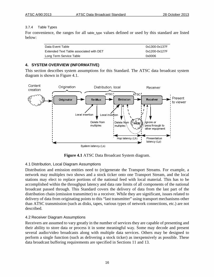
4. SYSTEM OVERVIEW (INFORMATIVE) This section describes system assumptions for this Standard. The ATSC data broadcast system diagram is shown in Figure 4.1.
Figure 4.1 ATSC Data Broadcast System diagram.
4.1 Distribution, Local Diagram Assumptions Distribution and emission entities need to (re)generate the Transport Streams. For example, a network may multiplex two shows and a stock ticker onto one Transport Stream, and the local stations may elect to replace portions of the national feed with local material. This has to be accomplished within the throughput latency and data rate limits of all components of the national broadcast passed through. This Standard covers the delivery of data from the last part of the distribution chain (emission transmitter) to a receiver. While they are significant, issues related to delivery of data from originating points to this “last transmitter” using transport mechanisms other than ATSC transmission (such as disks, tapes, various types of network connections, etc.) are not described.
4.2 Receiver Diagram Assumptions Receivers are assumed to vary greatly in the number of services they are capable of presenting and their ability to store data or process it in some meaningful way. Some may decode and present several audio/video broadcasts along with multiple data services. Others may be designed to perform a single function (such as delivering a stock ticker) as inexpensively as possible. These data broadcast buffering requirements are specified in Sections 11 and 13.
ATSC A/90:2013 ATSC Data Broadcast Standard 28 October 2013
17
5. OVERVIEW OF THE DATA BROADCASTING MECHANISMS (INFORMATIVE) The following is a brief description of the data carriage mechanisms defined in the ATSC Data Broadcast Standard. Please see A/91 [15] for additional explanations.
5.1 Data Download Protocol This document defines the carriage of data using the non-flow controlled scenario and the data carousel scenario of the DSM-CC User-to-Network Download protocol defined in ISO/IEC 13818-6 [9]. The ATSC use of the DSM-CC Download protocol supports the transmission of the following: asynchronous data modules, asynchronous data streaming, and non-streaming synchronized data. Non-streaming synchronized data is conveyed in data modules encapsulated in DSM-CC sections including Presentation Time Stamp (PTS) values as defined in ISO/IEC 13818-1 [8]. An example is sporadically transmitted application data temporally associated with a video stream.
Data carried by the Download protocol may be error protected, since the DSM-CC sections used for this protocol include a CRC_32 or a checksum field.
5.2 DSM-CC Addressable Sections This document defines transmission of datagrams in the payload of MPEG-2 Transport Stream packets by encapsulating the datagrams in DSM-CC addressable sections. This mechanism shall be used for the asynchronous delivery of datagrams.
5.3 Asynchronous Data Asynchronous data has the following characteristics:
• There is no MPEG-2 Systems ISO/IEC 13818-1 [8] timing associated with the delivery of data
• The smoothing buffer can go empty for indeterminate periods of time • The data is carried in DSM-CC sections or DSM-CC addressable sections
5.4 Synchronous and Synchronized Streaming Data This document supports synchronous and synchronized data streaming using PES.
Synchronous data streaming is defined as the streaming of data with timing requirements in the sense that the data and clock can be regenerated at the receiver into a synchronous data stream. Synchronous data streams have no strong timing association with other data streams and shall be carried in PES packets.
Synchronized data streaming implies a strong timing association between PES streams referenced by different PIDs. Synchronized streaming data shall be carried in PES packets. An example is application data associated with a video stream.
Synchronous or synchronized multiprotocol datagrams shall be carried in PES packets. For an MPEG-2 Program including at least one synchronized or synchronous data elementary
stream, a valid PCR_PID value shall be specified in the Program Map Table in which the program is listed and in particular, the PCR_PID value shall not be equal to 0x1FFF. Furthermore, as required in Section 2.7.2 of ISO/IEC 13818-1 [8], the time interval between successive occurrences of the PCR base field in Transport Stream packets of the Program element referenced by the PID value PCR_PID is less than or equal to 100 milliseconds. The same PCR_PID value shall appear in the
ATSC A/90:2013 ATSC Data Broadcast Standard 28 October 2013
18
Service Location Descriptor (see A/65 [3]) of the virtual channel that includes the synchronized and/or synchronous data elementary stream.
5.5 Data Piping This document defines data piping as a mechanism for delivery of arbitrary user defined data inside an MPEG-2 Transport Stream. Data is inserted directly into the payload of MPEG-2 Transport Stream packets. No methods are specified in this standard for fragmentation or re-assembly of data sent in this manner.
5.6 Data Services A data service is a collection of one or more applications. Each application is a collection of one or more data broadcast types. For example, a data service may include applications that contain streaming synchronized data and asynchronous multiprotocol encapsulated data.
6. DSM-CC COMPATIBILITY DESCRIPTOR The DSM-CC compatibility descriptor is used in both the DSM-CC User-to-Network Download protocol (see Section 7) and the Service Description Framework (see Section 12). The compatibility descriptor may be used to specify data receiver hardware and/or software requirements for proper acquisition and rendering of a data service.
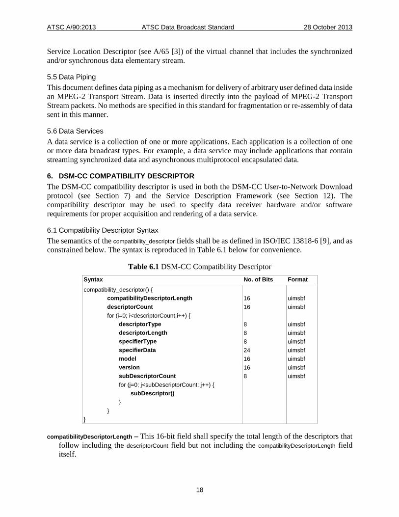
6.1 Compatibility Descriptor Syntax The semantics of the compatibility_descriptor fields shall be as defined in ISO/IEC 13818-6 [9], and as constrained below. The syntax is reproduced in Table 6.1 below for convenience.
Table 6.1 DSM-CC Compatibility Descriptor Syntax No. of Bits Format compatibility_descriptor() { compatibilityDescriptorLength 16 uimsbf descriptorCount 16 uimsbf for (i=0; i<descriptorCount;i++) { descriptorType 8 uimsbf descriptorLength 8 uimsbf specifierType 8 uimsbf specifierData 24 uimsbf model 16 uimsbf version 16 uimsbf subDescriptorCount 8 uimsbf for (j=0; j<subDescriptorCount; j++) { subDescriptor() } } }
compatibilityDescriptorLength – This 16-bit field shall specify the total length of the descriptors that follow including the descriptorCount field but not including the compatibilityDescriptorLength field itself.
ATSC A/90:2013 ATSC Data Broadcast Standard 28 October 2013
19
descriptorCount – This 16-bit field shall specify the number of descriptors which follow the descriptorCount field.
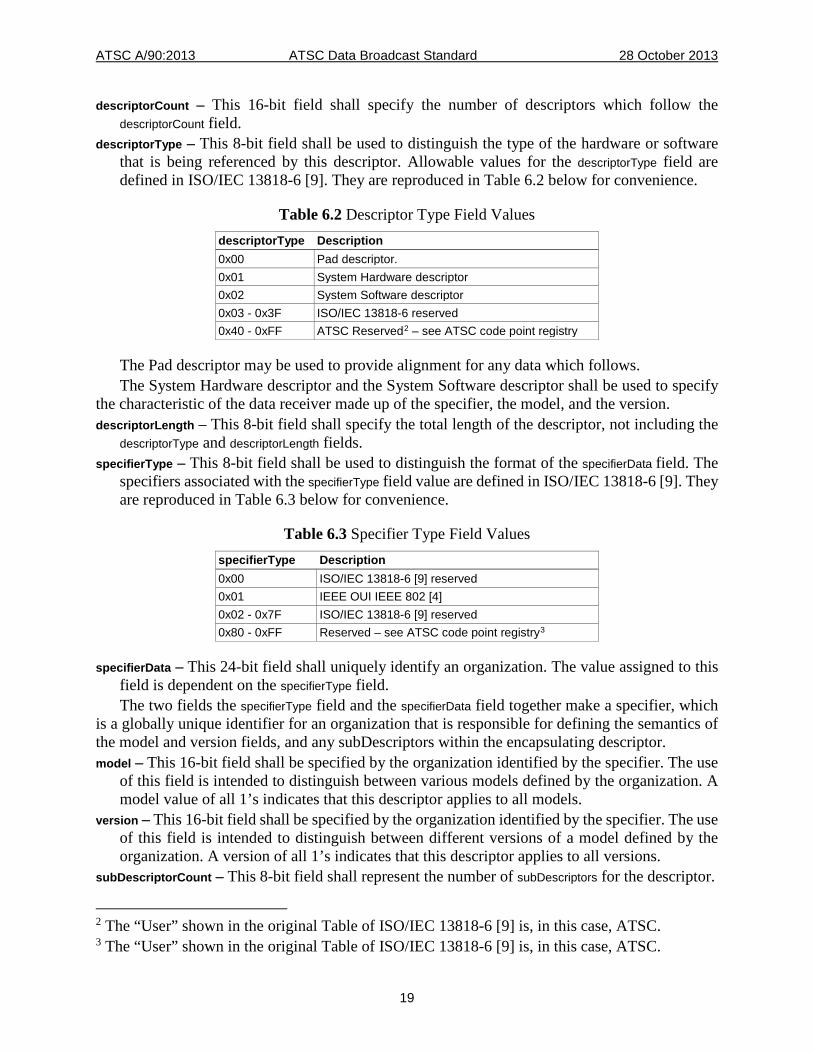
descriptorType – This 8-bit field shall be used to distinguish the type of the hardware or software that is being referenced by this descriptor. Allowable values for the descriptorType field are defined in ISO/IEC 13818-6 [9]. They are reproduced in Table 6.2 below for convenience.
Table 6.2 Descriptor Type Field Values descriptorType Description 0x00 Pad descriptor. 0x01 System Hardware descriptor 0x02 System Software descriptor 0x03 - 0x3F ISO/IEC 13818-6 reserved 0x40 - 0xFF ATSC Reserved2 – see ATSC code point registry
The Pad descriptor may be used to provide alignment for any data which follows. The System Hardware descriptor and the System Software descriptor shall be used to specify
the characteristic of the data receiver made up of the specifier, the model, and the version. descriptorLength – This 8-bit field shall specify the total length of the descriptor, not including the
descriptorType and descriptorLength fields. specifierType – This 8-bit field shall be used to distinguish the format of the specifierData field. The
specifiers associated with the specifierType field value are defined in ISO/IEC 13818-6 [9]. They are reproduced in Table 6.3 below for convenience.
Table 6.3 Specifier Type Field Values specifierType Description 0x00 ISO/IEC 13818-6 [9] reserved 0x01 IEEE OUI IEEE 802 [4] 0x02 - 0x7F ISO/IEC 13818-6 [9] reserved 0x80 - 0xFF Reserved – see ATSC code point registry3
specifierData – This 24-bit field shall uniquely identify an organization. The value assigned to this field is dependent on the specifierType field. The two fields the specifierType field and the specifierData field together make a specifier, which
is a globally unique identifier for an organization that is responsible for defining the semantics of the model and version fields, and any subDescriptors within the encapsulating descriptor. model – This 16-bit field shall be specified by the organization identified by the specifier. The use
of this field is intended to distinguish between various models defined by the organization. A model value of all 1’s indicates that this descriptor applies to all models.
version – This 16-bit field shall be specified by the organization identified by the specifier. The use of this field is intended to distinguish between different versions of a model defined by the organization. A version of all 1’s indicates that this descriptor applies to all versions.
subDescriptorCount – This 8-bit field shall represent the number of subDescriptors for the descriptor.
2 The “User” shown in the original Table of ISO/IEC 13818-6 [9] is, in this case, ATSC. 3 The “User” shown in the original Table of ISO/IEC 13818-6 [9] is, in this case, ATSC.
ATSC A/90:2013 ATSC Data Broadcast Standard 28 October 2013
20
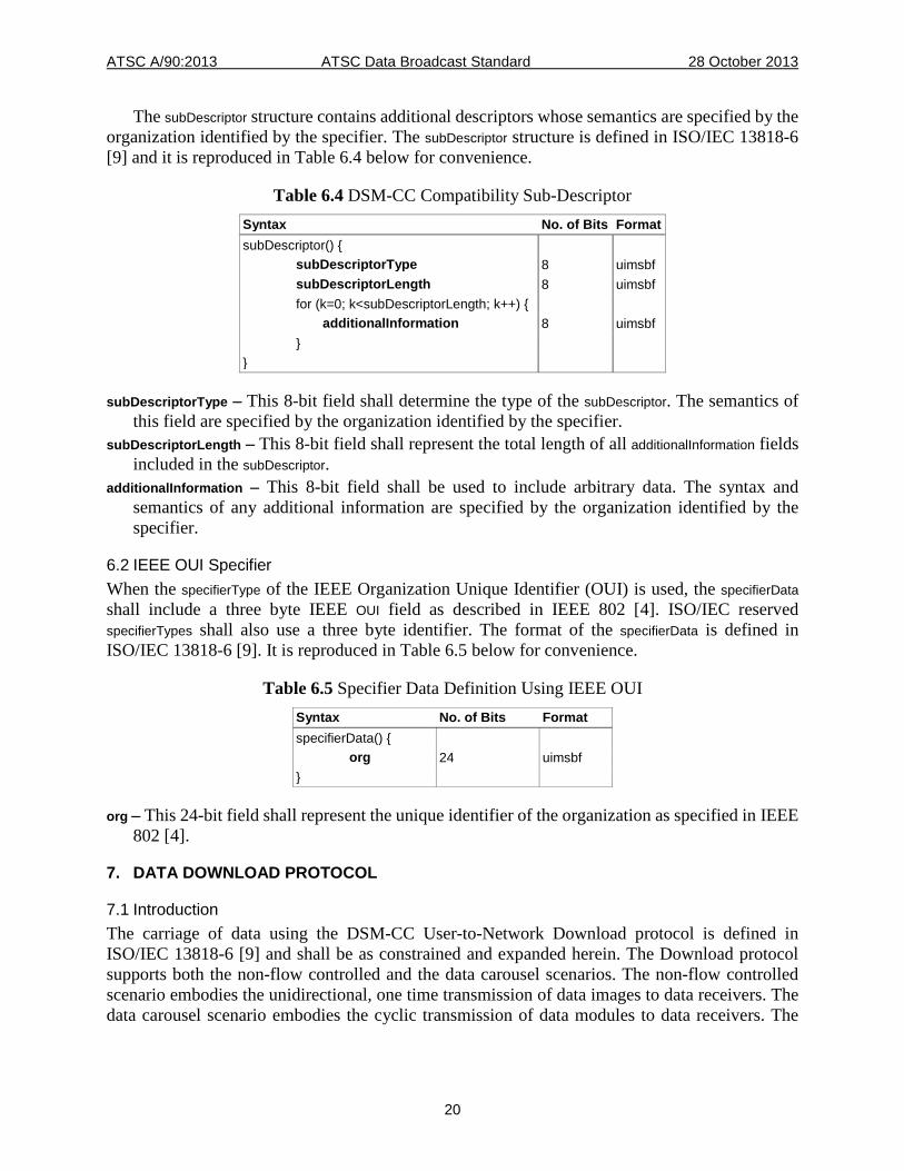
The subDescriptor structure contains additional descriptors whose semantics are specified by the organization identified by the specifier. The subDescriptor structure is defined in ISO/IEC 13818-6 [9] and it is reproduced in Table 6.4 below for convenience.
Table 6.4 DSM-CC Compatibility Sub-Descriptor Syntax No. of Bits Format subDescriptor() { subDescriptorType 8 uimsbf subDescriptorLength 8 uimsbf for (k=0; k<subDescriptorLength; k++) { additionalInformation 8 uimsbf } }
subDescriptorType – This 8-bit field shall determine the type of the subDescriptor. The semantics of this field are specified by the organization identified by the specifier.
subDescriptorLength – This 8-bit field shall represent the total length of all additionalInformation fields included in the subDescriptor.
additionalInformation – This 8-bit field shall be used to include arbitrary data. The syntax and semantics of any additional information are specified by the organization identified by the specifier.
6.2 IEEE OUI Specifier When the specifierType of the IEEE Organization Unique Identifier (OUI) is used, the specifierData shall include a three byte IEEE OUI field as described in IEEE 802 [4]. ISO/IEC reserved specifierTypes shall also use a three byte identifier. The format of the specifierData is defined in ISO/IEC 13818-6 [9]. It is reproduced in Table 6.5 below for convenience.
Table 6.5 Specifier Data Definition Using IEEE OUI Syntax No. of Bits Format specifierData() { org 24 uimsbf }
org – This 24-bit field shall represent the unique identifier of the organization as specified in IEEE 802 [4].
7. DATA DOWNLOAD PROTOCOL
7.1 Introduction The carriage of data using the DSM-CC User-to-Network Download protocol is defined in ISO/IEC 13818-6 [9] and shall be as constrained and expanded herein. The Download protocol supports both the non-flow controlled and the data carousel scenarios. The non-flow controlled scenario embodies the unidirectional, one time transmission of data images to data receivers. The data carousel scenario embodies the cyclic transmission of data modules to data receivers. The
ATSC A/90:2013 ATSC Data Broadcast Standard 28 October 2013
21
data is organized into modules divided into blocks. All blocks of a module shall be of the same size except for the last block, which may be of a smaller size.
This Standard shall use the DownloadDataBlock, the DownloadServerInitiate, the DownloadInfoIndication and the DownloadCancel messages of the Download protocol. The data shall be carried in the DownloadDataBlock data messages, while the control information shall use the DownloadServerInitiate, the DownloadInfoIndication and the DownloadCancel control messages. A Download scenario may include either one or two layers of control information. In the latter case, a DownloadServerInitiate message is used. The DownloadInfoIndication messages describe the modules. All modules of a download scenario shall be announced in the DownloadInfoIndication messages. 7.1.1 Transmission of Streaming and Non-streaming Asynchronous Data The Download protocol is used to carry asynchronous data in the form of bounded data modules. The moduleSize field associated with a bounded data module shall be set to a non-zero value. For a given moduleId and moduleVersion value, the maximum data module size is 266,469,376 bytes4. The Download protocol may also be used to carry asynchronous streaming data. The moduleId, moduleSize, moduleVersion, and moduleInfoLength fields associated with a data module conveying asynchronous streaming data shall be listed in at least one of the DownloadInfoIndication messages and the value of the moduleSize field shall be set to 0. The stream type value associated with the asynchronous DSM-CC User-to-Network Download protocol shall be equal to 0x0B. Consequently, the non-flow controlled scenario and the carousel scenario share the same stream_type value. However, they shall not share the same elementary_PID value in a single Transport Stream. The use of the payload_unit_start_indicator in the MPEG-2 Transport packet header and the use of the pointer field in the Transport packet payload shall comply with ISO/IEC 13818-1 [8] and ISO/IEC 13818-6 [9]. 7.1.2 Transmission of Non-streaming, Synchronized Data The non-flow controlled scenario of the Download protocol may also be used to convey non-streaming, synchronized data modules. This mode is supported by adding time information in the adaptation header in the DownloadDataBlock message as specified in ISO/IEC 13818-6 [9]. The resulting protocol is called the Synchronized Download protocol. Time information in the adaptation header shall be a PTS as defined in ISO/IEC 13818-6 [9]. The PTS field shall appear in the first DSM-CC section conveying the first block of any data module (blockNumber equal to 0x0000) in the data elementary stream, and it shall not appear in the DSM-CC sections conveying any other blocks of the same data module (blockNumber greater than 0x0000) in the same data elementary stream. The payload_unit_start_indicator field in any MPEG-2 Transport Stream packet conveying the beginning of a DSM-CC section containing non-streaming, synchronized data shall be set to ‘1’ and the value of the pointer_field shall be set to ‘0’ to indicate that the DSM-CC section starts immediately after the pointer_field. The purpose of this constraint is to fix the position of the PTS in the Transport Stream packets. Furthermore, in this case, an MPEG-2 Transport Stream packet shall not include the beginning of more than one DSM-CC section. Within a single Download scenario, the transmission of all Sections belonging to a single synchronized data module shall be finished before the transmission of the next synchronized data module is allowed to be started. This constraint is necessary to ensure proper reconstruction of each synchronized
4 This value is obtained by considering the maximum size of a module block in a DSM-CC section
and the largest number of blocks in a data module.
ATSC A/90:2013 ATSC Data Broadcast Standard 28 October 2013
22
data module in the Data Elementary Buffer of the T-STD for synchronized data elementary streams.
For an MPEG-2 Program including at least one non-streaming, synchronized data elementary stream, a valid PCR_PID value shall be specified in the Program Map Table in which the program is listed and in particular, the PCR_PID value shall not be equal to 0x1FFF. Furthermore, as required in Section 2.7.2 of ISO/IEC 13818-1 [8], the time interval between successive occurrences of the PCR base field in Transport Stream packets of the Program element referenced by the PID value PCR_PID is less than or equal to 100 milliseconds. The same PCR_PID value shall appear in the Service Location Descriptor of the virtual channel that includes the non-streaming, synchronized data elementary stream.
The stream_type value associated with the synchronized non-flow controlled scenario of the Download protocol shall be equal to 0x14. For a given moduleId and moduleVersion value, the maximum data module size is 265,945,088 bytes5. Finally, in the download_descriptor (defined in the Service Description Framework section below), the value of the carousel_period field shall be set to 0 to indicate the synchronized non-flow controlled scenario of the Download protocol.
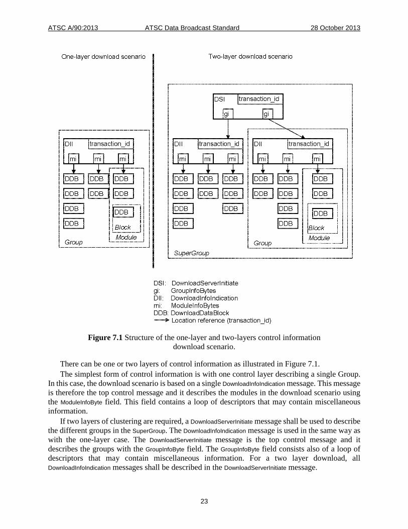
All synchronized data modules belonging to a single download scenario shall be listed in the DownloadInfoIndication messages. Any synchronized data module shall be of finite length, meaning that the size of the module (the value of the moduleSize field in the DownloadInfoIndication message) shall always be specified and greater than 0. 7.1.3 Structure of the Non-flow Controlled and Carousel Scenarios The specification of the non-flow controlled scenario and the carousel scenario is based on the DSM-CC data carousel specification ISO/IEC 13818-6 [9]. The DSM-CC non-flow controlled scenario embodies the download of a data image while the data carousel scenario embodies the cyclic transmission of data. The data transmitted is organized in "modules" which are divided into “blocks”. All blocks of all modules within the data carousel are of the same size, except for the last block of each module which may be of a smaller size. Modules are a delineation of logically separate groups of data within the data carousel. Modules can be clustered into a Group of modules if required by the service (one-layer control information). Likewise, Groups can in turn be clustered into SuperGroups (two-layer control information).
The data carousel specification uses four messages of the DSM-CC download protocol. The data shall be carried in DownloadDataBlock messages, while the control over the modules shall be provided by the DownloadInfoIndication, DownloadServerInitiate, and DownloadCancel messages. The DownloadServerInitiate message describes the groups in a SuperGroup, while the DownloadInfoIndication message describes the modules in a Group. Based on the control messages, the receivers may acquire a subset of the modules from the network. The use of these messages is described in this Standard. Use of other messages is beyond the scope of this standard.
5 This value is obtained by considering the size of the DSM-CC adaptation header, the maximum
size of a module block in a DSM-CC section and the largest number of blocks in a data module.
ATSC A/90:2013 ATSC Data Broadcast Standard 28 October 2013
23
Figure 7.1 Structure of the one-layer and two-layers control information
download scenario.
There can be one or two layers of control information as illustrated in Figure 7.1. The simplest form of control information is with one control layer describing a single Group.
In this case, the download scenario is based on a single DownloadInfoIndication message. This message is therefore the top control message and it describes the modules in the download scenario using the ModuleInfoByte field. This field contains a loop of descriptors that may contain miscellaneous information.
If two layers of clustering are required, a DownloadServerInitiate message shall be used to describe the different groups in the SuperGroup. The DownloadInfoIndication message is used in the same way as with the one-layer case. The DownloadServerInitiate message is the top control message and it describes the groups with the GroupInfoByte field. The GroupInfoByte field consists also of a loop of descriptors that may contain miscellaneous information. For a two layer download, all DownloadInfoIndication messages shall be described in the DownloadServerInitiate message.
ATSC A/90:2013 ATSC Data Broadcast Standard 28 October 2013
24
The one and two layer control information designs are applicable to both the asynchronous and synchronized Download protocols.
Either the one-layer or the two-layer control information may be used. Each arrow in Figure 7.1 represents the access information that is required to acquire the message(s) to which the arrow points. This information consists of a transaction/module identifier, i.e. a unique identifier of a control message or a module. Furthermore, in the DownloadServerInitiate and DownloadInfoIndication messages, parameters for the sizes of modules and blocks have been specified, per DSM-CC Standard ISO/IEC 13818-6 [9].
All DownloadDataBlock and DownloadInfoIndication messages within a SuperGroup (in the case of two layer control information) or a Group (in the case of single layer control information) share the same downloadId. This implies that groups can share modules because all moduleId field values are unique within the scope of the downloadId.
Each control message has a transaction_id which is the unique identifier of the message. The transaction_id and moduleId fields can be used to efficiently filter the data of the data download. In particular, the transaction_id shall be a composite field where the two least significant bytes are used to convey a version update 1-bit flag and a 15-bit message identification field. The following semantics shall apply to the two least significant bytes of the transaction_id field:
Two-layer control information case: For DownloadServerInitiate messages the 2 least significant bytes of the transaction_id shall be in
the range 0x0000-0x0001. For DownloadInfoIndication messages: the 2 least significant bytes of the transaction_id shall be
in the range 0x0002-0xFFFF. One-layer control scenario case:
For DownloadInfoIndication messages: the 2 least significant bytes of the transaction_id shall be in the range 0x0000-0x0001.
The transaction_id field shall have a dual role, providing both identification and versioning mechanisms for download control messages; i.e., DownloadInfoIndication and DownloadServerInitiate messages. The transaction_id field shall uniquely identify a download control message within a download scenario. The value of this field shall be modified whenever any field of the message is modified.
Due to the role of the transaction_id as a versioning mechanism any change to any message in the Download scenario will cause the transaction_id of the top-layer control message to be modified. The change shall propagate up through the structure of the Download protocol as follows. Any change to a data module shall necessitate incrementing its moduleVersion field. This change shall be reflected in the corresponding field in the description of the Module in the DownloadInfoIndication message(s) that describes any Group(s) that includes it. Since a field in the DownloadInfoIndication message is changed, the value of the bit field of the transaction_id representing the control message version (bits 16 to 29 included) shall be modified to indicate a new version of the message. Again (in the case of a two-layer control information) this change shall be reflected in the corresponding field in the description of the Group in the DownloadServerInitiate message that describes the SuperGroup. Since fields in the DownloadServerInitiate message have changed its transaction_id shall also be modified. This is useful since just by looking at the transaction_id of the top-layer control message a change to any message in the Download scenario can be detected.
The encapsulation of download control messages within MPEG-2 Transport Streams is defined in ISO/IEC 13818-6 [9]. It specifies that the two least significant bytes of the transaction_id field are
ATSC A/90:2013 ATSC Data Broadcast Standard 28 October 2013
25
copied into the table_id_extension field of the DSMCC_section header. This means that if the PID value of the Transport Stream packets on which the Download scenario is being broadcast is known, the top-layer control message can be located without knowing its transaction_id by setting up the Section filters for table_id = 0x3B (download control messages) and table_id_extension = 0x0000 or 0x0001.
7.2 Data Download Protocol Specification DSM-CC sections convey both control and data messages of the Download protocol. The required control messages shall be the DownloadInfoIndication, the DownloadServerInitiate message and the DownloadCancel message. The required data Download message shall be the DownloadDataBlock message that carries the data modules. Use of other messages is beyond the scope of this standard. The DSM-CC sections carrying all of the Download protocol messages of the same Download scenario shall be conveyed in a single data elementary stream. Consequently, the Transport Stream packets conveying this data elementary stream shall have the same elementary_PID value. A data elementary stream of stream_type value 0x0B or 0x14 shall convey one and only one Download scenario.
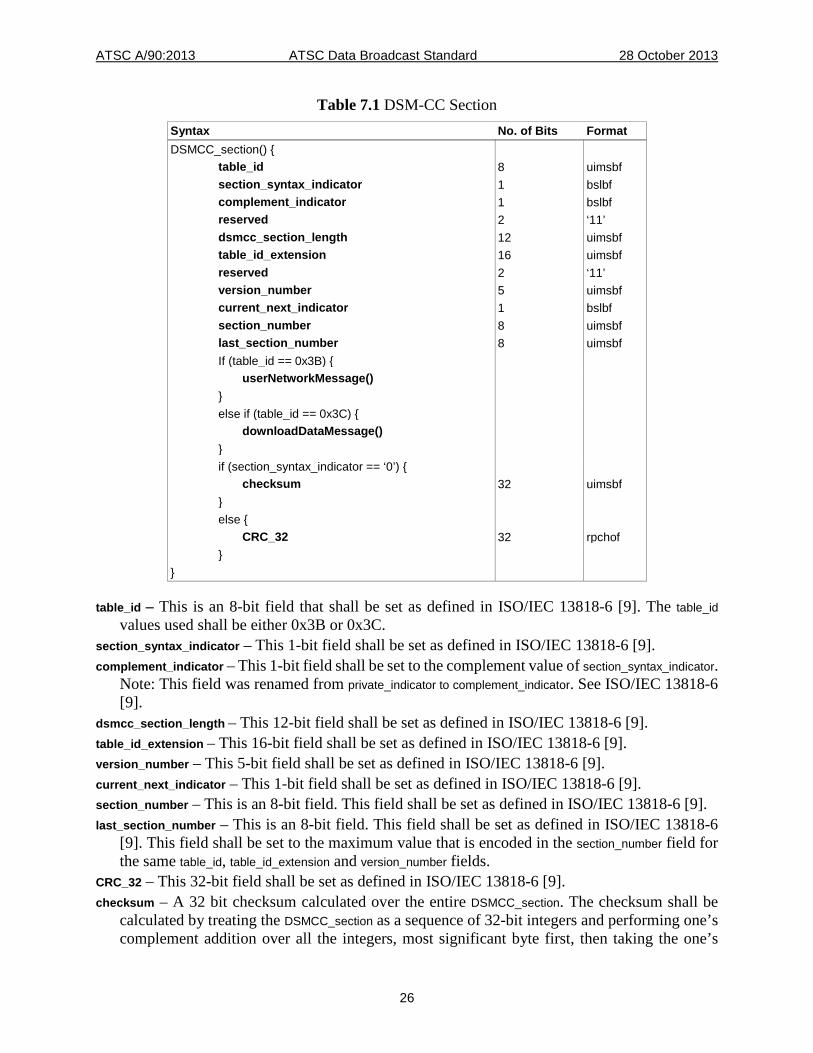
All rules for the encapsulation of DSM-CC sections in MPEG-2 Transport Streams specified in Section 9 of ISO/IEC 13818-6 [9] shall apply. 7.2.1 DSM-CC Section Syntax for User-to-Network Download Protocol The DSM-CC section structure and values are defined in ISO/IEC 13818-6 [9], and are reproduced in Table 7.1 for convenience.
ATSC A/90:2013 ATSC Data Broadcast Standard 28 October 2013
26
Table 7.1 DSM-CC Section Syntax No. of Bits Format DSMCC_section() { table_id 8 uimsbf section_syntax_indicator 1 bslbf complement_indicator 1 bslbf reserved 2 ‘11’ dsmcc_section_length 12 uimsbf table_id_extension 16 uimsbf reserved 2 ‘11’ version_number 5 uimsbf current_next_indicator 1 bslbf section_number 8 uimsbf last_section_number 8 uimsbf If (table_id == 0x3B) { userNetworkMessage() } else if (table_id == 0x3C) { downloadDataMessage() } if (section_syntax_indicator == ‘0’) { checksum 32 uimsbf } else { CRC_32 32 rpchof } }
table_id – This is an 8-bit field that shall be set as defined in ISO/IEC 13818-6 [9]. The table_id values used shall be either 0x3B or 0x3C.
section_syntax_indicator – This 1-bit field shall be set as defined in ISO/IEC 13818-6 [9]. complement_indicator – This 1-bit field shall be set to the complement value of section_syntax_indicator.
Note: This field was renamed from private_indicator to complement_indicator. See ISO/IEC 13818-6 [9].
dsmcc_section_length – This 12-bit field shall be set as defined in ISO/IEC 13818-6 [9]. table_id_extension – This 16-bit field shall be set as defined in ISO/IEC 13818-6 [9]. version_number – This 5-bit field shall be set as defined in ISO/IEC 13818-6 [9]. current_next_indicator – This 1-bit field shall be set as defined in ISO/IEC 13818-6 [9]. section_number – This is an 8-bit field. This field shall be set as defined in ISO/IEC 13818-6 [9]. last_section_number – This is an 8-bit field. This field shall be set as defined in ISO/IEC 13818-6
[9]. This field shall be set to the maximum value that is encoded in the section_number field for the same table_id, table_id_extension and version_number fields.
CRC_32 – This 32-bit field shall be set as defined in ISO/IEC 13818-6 [9]. checksum – A 32 bit checksum calculated over the entire DSMCC_section. The checksum shall be
calculated by treating the DSMCC_section as a sequence of 32-bit integers and performing one’s complement addition over all the integers, most significant byte first, then taking the one’s
ATSC A/90:2013 ATSC Data Broadcast Standard 28 October 2013
27
complement of the result. For the purpose of computing the checksum, the value of the checksum field shall be considered ‘0’. If the message length is not a multiple of four bytes, the message shall be considered to be appended with zeroed bytes for the purpose of checksum calculation only. If the computed result is ‘0’, then the result shall be set to 0xFFFFFFFF (the alternative value for a one’s complement representation of ‘0’). In cases where a checksum is not desired, the value of this field shall be set to ‘0’ to indicate the checksum has not been calculated. This feature is useful for networks where error detection is provided at a protocol layer lower than the MPEG-2 Transport Stream. The header bytes of a DSMCC_section structure shall be defined as the eight bytes at the
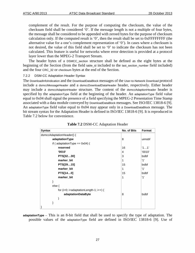
beginning of the Section (from the field table_id included to the last_section_number field included) and the four CRC_32 or checksum bytes at the end of the Section. 7.2.2 DSM-CC Adaptation Header Syntax The DownloadInfoIndication and the DownloadDataBlock messages of the User-to-Network Download protocol include a dsmccMessageHeader and a dsmccDownloadDataHeader header, respectively. Either header may include a dsmccAdaptionHeader structure. The content of the dsmccAdaptionHeader header is specified by the adaptationType field at the beginning of the header. An adaptationType field value equal to 0x04 shall signal the presence of a field specifying the MPEG-2 Presentation Time Stamp associated with a data module conveyed by DownloadDataBlock messages. See ISO/IEC 13818-6 [9]. An adaptationType field value equal to 0x04 may appear only in a DownloadDataBlock message. The bit stream syntax for the Adaptation Header is defined in ISO/IEC 13818-6 [9]. It is reproduced in Table 7.2 below for convenience.
Table 7.2 DSM-CC Adaptation Header Syntax No. of Bits Format dsmccAdaptationHeader() { adaptationType 8 uimsbf if ( adaptationType == 0x04) { reserved 16 ‘1…1’ '0010' 4 ‘0010’ PTS[32…30] 3 bslbf marker_bit 1 '1' PTS[29…15] 15 bslbf marker_bit 1 '1' PTS[14…0] 15 bslbf marker_bit 1 '1' } else { for (i=0; i<adaptationLength-1; i++) { adaptationDataByte 8 bslbf } } }
adaptationType – This is an 8-bit field that shall be used to specify the type of adaptation. The possible values of the adaptationType field are defined in ISO/IEC 13818-6 [9]. Use of
ATSC A/90:2013 ATSC Data Broadcast Standard 28 October 2013
28
adaptationType values other than 0x04 is beyond the scope of this standard. The adaptationType 0x04 shall indicate the presence of a Synchronized Download protocol adaptation format.
marker_bit – This is a one bit field. Each instance of this field shall be set to ‘1’. PTS – This 33-bit field represents a Presentation Time Stamp as defined in ISO/IEC 13818-1 [8].
This field shall specify the intended time of presentation of the data module. The 33-bit PTS field shall be reconstructed from the in order concatenation of the PTS[32…30], PTS[29…15], and PTS[14…0] fields, representing bit number 32 to 30, bit number 29 to 15 and bit number 14 to 0 of the Presentation Time Stamp, respectively.
adaptationLength – This 8-bit field specifies the length of the adaptation fields. This field is defined in Table 7.3 below.
adaptationDataByte – This 8-bit field represents a byte of the adaptation header. 7.2.3 Download Control Messages Control messages defined in ISO/IEC 13818-6 [9] and used by this standard are the DownloadInfoIndication message, the DownloadServerInitiate message, and the DownloadCancel message.
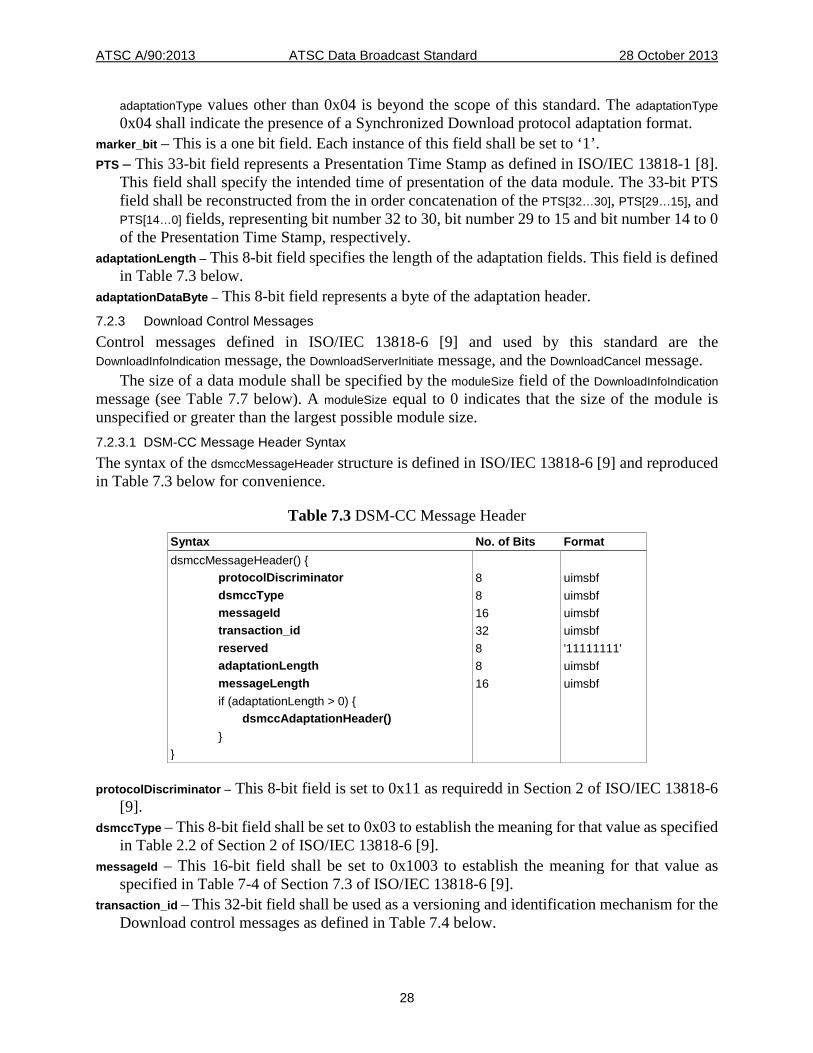
The size of a data module shall be specified by the moduleSize field of the DownloadInfoIndication message (see Table 7.7 below). A moduleSize equal to 0 indicates that the size of the module is unspecified or greater than the largest possible module size. 7.2.3.1 DSM-CC Message Header Syntax The syntax of the dsmccMessageHeader structure is defined in ISO/IEC 13818-6 [9] and reproduced in Table 7.3 below for convenience.
Table 7.3 DSM-CC Message Header Syntax No. of Bits Format dsmccMessageHeader() { protocolDiscriminator 8 uimsbf dsmccType 8 uimsbf messageId 16 uimsbf transaction_id 32 uimsbf reserved 8 '11111111' adaptationLength 8 uimsbf messageLength 16 uimsbf if (adaptationLength > 0) { dsmccAdaptationHeader() } }
protocolDiscriminator – This 8-bit field is set to 0x11 as requiredd in Section 2 of ISO/IEC 13818-6 [9].
dsmccType – This 8-bit field shall be set to 0x03 to establish the meaning for that value as specified in Table 2.2 of Section 2 of ISO/IEC 13818-6 [9].
messageId – This 16-bit field shall be set to 0x1003 to establish the meaning for that value as specified in Table 7-4 of Section 7.3 of ISO/IEC 13818-6 [9].
transaction_id – This 32-bit field shall be used as a versioning and identification mechanism for the Download control messages as defined in Table 7.4 below.

ATSC A/90:2013 ATSC Data Broadcast Standard 28 October 2013
29
Table 7.4 Semantics of the Transaction ID Field Bits Value Sub-field Description transaction_id[31..30] '10’ Control message
originator The value of this 2-bit field is defined in [9] as equal to 0x02 when the transaction_id has been assigned by the network - In a broadcast scenario this is implicit.
transaction_id[29..16] User-defined
Control message version
This 14-bit field shall be modified every time the control message is updated.
transaction_id[15..1] User-defined
Control message identification
This 15-bit field shall be used to identify the control message. This must and can only be all zeros for the top-layer control message. All non-top-level control messages must have one or more non-zero bit(s).
transaction_id[0] User-defined
Updated flag This 1-bit field must be toggled every time the control message is updated.
adaptationLength – This 8-bit field shall be set as defined in ISO/IEC 13818-6 [9]. messageLength – This 16-bit field shall be set as defined in ISO/IEC 13818-6 [9]. 7.2.3.2 Download Server Initiate Message Syntax The syntax and field semantics of the DownloadServerInitiate message are defined in ISO/IEC 13818-6 [9]. It is reproduced in Table 7.5 below for convenience.
Table 7.5 Download Server Initiate Message Syntax No. of Bits Format DownloadServerInitiate() { dsmccMessageHeader() serverId 160 uimsbf compatibility_descriptor() privateDataLength 16 uimsbf for (i = 0; i< privateDataLength; i++) { privateDataByte 8 uimsbf } }
serverId – This 160-bit field shall be set to 0xFFFF FFFF FFFF FFFF FFFF FFFF FFFF FFFF FFFF FFFF.
compatibility_descriptor() – This structure shall be as described in Section 6 of this standard. The value of the compatibilityDescriptorLength shall be equal to 0x0000.
privateDataLength – This 16-bit field shall define the length in bytes of the following private data bytes.
privateDataByte – This 8-bit field shall represent a byte of the private data field. The private data fields shall only consist of the GroupInfoIndication structure defined in Table 7.6 below.
ATSC A/90:2013 ATSC Data Broadcast Standard 28 October 2013
30
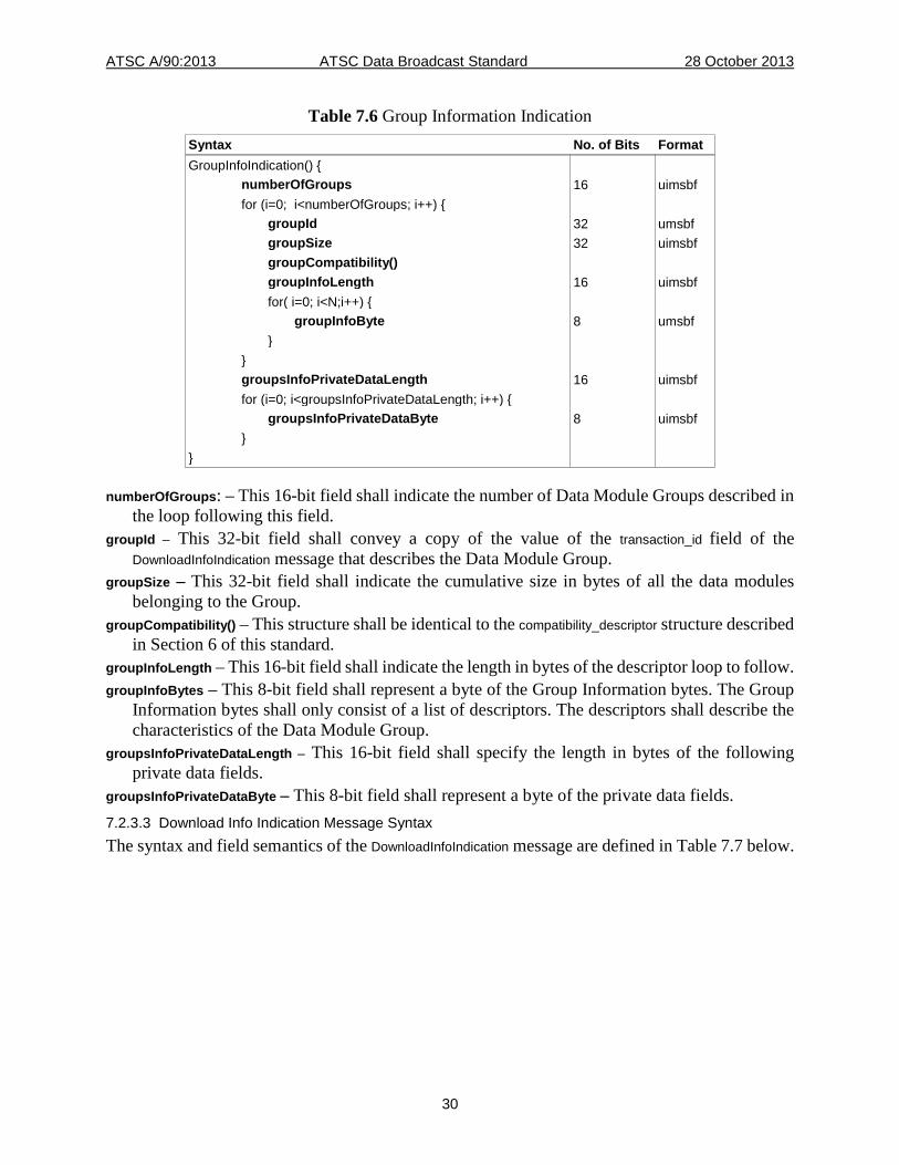
Table 7.6 Group Information Indication Syntax No. of Bits Format GroupInfoIndication() { numberOfGroups 16 uimsbf for (i=0; i<numberOfGroups; i++) { groupId 32 umsbf groupSize 32 uimsbf groupCompatibility() groupInfoLength 16 uimsbf for( i=0; i<N;i++) { groupInfoByte 8 umsbf } } groupsInfoPrivateDataLength 16 uimsbf for (i=0; i<groupsInfoPrivateDataLength; i++) { groupsInfoPrivateDataByte 8 uimsbf } }
numberOfGroups: – This 16-bit field shall indicate the number of Data Module Groups described in the loop following this field.
groupId – This 32-bit field shall convey a copy of the value of the transaction_id field of the DownloadInfoIndication message that describes the Data Module Group.
groupSize – This 32-bit field shall indicate the cumulative size in bytes of all the data modules belonging to the Group.
groupCompatibility() – This structure shall be identical to the compatibility_descriptor structure described in Section 6 of this standard.
groupInfoLength – This 16-bit field shall indicate the length in bytes of the descriptor loop to follow. groupInfoBytes – This 8-bit field shall represent a byte of the Group Information bytes. The Group
Information bytes shall only consist of a list of descriptors. The descriptors shall describe the characteristics of the Data Module Group.
groupsInfoPrivateDataLength – This 16-bit field shall specify the length in bytes of the following private data fields.
groupsInfoPrivateDataByte – This 8-bit field shall represent a byte of the private data fields. 7.2.3.3 Download Info Indication Message Syntax The syntax and field semantics of the DownloadInfoIndication message are defined in Table 7.7 below.
ATSC A/90:2013 ATSC Data Broadcast Standard 28 October 2013
31
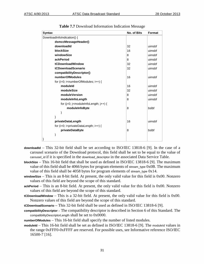
Table 7.7 Download Information Indication Message Syntax No. of Bits Format DownloadInfoIndication() { dsmccMessageHeader() downloadId 32 uimsbf blockSize 16 uimsbf windowSize 8 uimsbf ackPeriod 8 uimsbf tCDownloadWindow 32 uimsbf tCDownloadScenario 32 uimsbf compatibilityDescriptor() numberOfModules 16 uimsbf for (i=0; i<numberOfModules; i++) { moduleId 16 uimsbf moduleSize 32 uimsbf moduleVersion 8 uimsbf moduleInfoLength 8 uimsbf for (j=0; j<moduleInfoLength; j++) { moduleInfoByte 8 bslbf } } privateDataLength 16 uimsbf for (i=0; i<privateDataLength; i++) { privateDataByte 8 bslbf } }
downloadId – This 32-bit field shall be set according to ISO/IEC 13818-6 [9]. In the case of a carousel scenario of the Download protocol, this field shall be set to be equal to the value of carousel_id if it is specified in the download_descriptor in the associated Data Service Table.
blockSize – This 16-bit field that shall be used as defined in ISO/IEC 13818-6 [9]. The maximum value of this field shall be 4066 bytes for program elements of stream_type 0x0B. The maximum value of this field shall be 4058 bytes for program elements of stream_type 0x14.
windowSize – This is an 8-bit field. At present, the only valid value for this field is 0x00. Nonzero values of this field are beyond the scope of this standard.
ackPeriod – This is an 8-bit field. At present, the only valid value for this field is 0x00. Nonzero values of this field are beyond the scope of this standard.
tCDownloadWindow – This is a 32-bit field. At present, the only valid value for this field is 0x00. Nonzero values of this field are beyond the scope of this standard.
tCDownloadScenario – This 32-bit field shall be used as defined in ISO/IEC 13818-6 [9]. compatibilityDescriptor – The compatibility descriptor is described in Section 6 of this Standard. The
compatibilityDescriptorLength shall be set to 0x0000. numberOfModules – This 16-bit field shall specify the number of listed modules. moduleId – This 16-bit field shall be set as defined in ISO/IEC 13818-6 [9]. The moduleId values in
the range 0xFFF0-0xFFFF are reserved. For possible uses, see Informative reference ISO/IEC 16500-7 [16].
ATSC A/90:2013 ATSC Data Broadcast Standard 28 October 2013
32
moduleSize – This 32-bit field shall be set to the size of the data module in bytes when the module is bounded, or shall be set to 0x00000000 when the module size is unspecified.
moduleVersion – This 8-bit field shall be set as defined in ISO/IEC 13818-6 [9]. moduleInfoLength – This 8-bit field shall be set as defined in ISO/IEC 13818-6 [9]. If the value is
zero, then there are no moduleInfoBytes for the module being described. moduleInfoByte – This 8-bit quantity shall represent a byte of information describing the module.
For moduleId values in the range 0x0000-0xFFEF, the moduleInfoByte fields shall convey a moduleDescription structure as specified in Section 7.2.3.4. For moduleId values in the range 0xFFF0-0xFFFF, the moduleInfoByte fields shall contain the ModuleInfo structure are defined in 16500-7 [4].
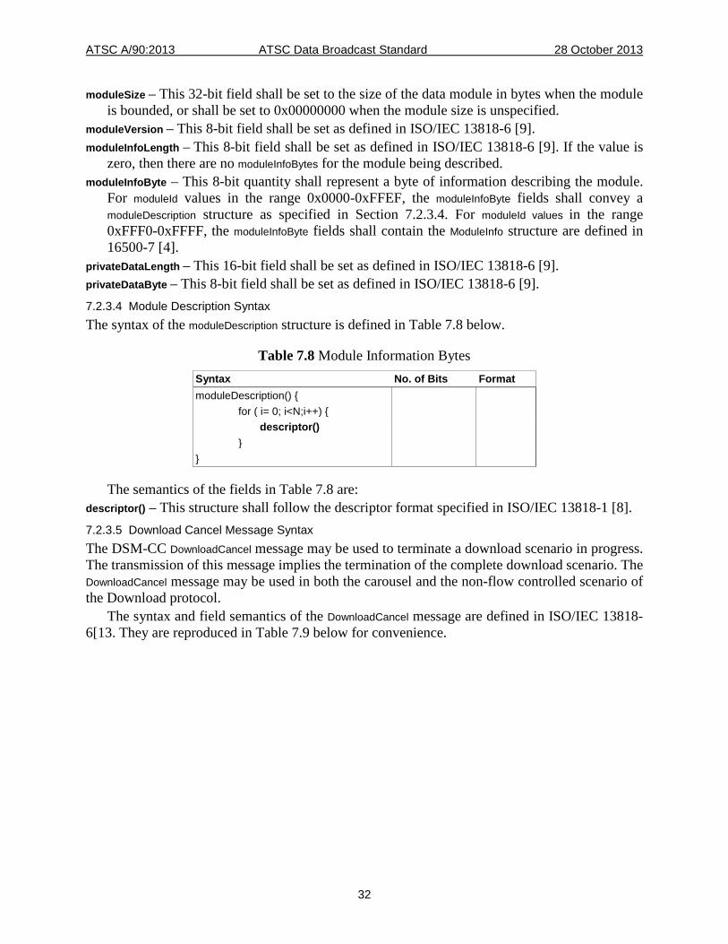
privateDataLength – This 16-bit field shall be set as defined in ISO/IEC 13818-6 [9]. privateDataByte – This 8-bit field shall be set as defined in ISO/IEC 13818-6 [9]. 7.2.3.4 Module Description Syntax The syntax of the moduleDescription structure is defined in Table 7.8 below.
Table 7.8 Module Information Bytes Syntax No. of Bits Format moduleDescription() { for ( i= 0; i<N;i++) { descriptor() } }
The semantics of the fields in Table 7.8 are: descriptor() – This structure shall follow the descriptor format specified in ISO/IEC 13818-1 [8]. 7.2.3.5 Download Cancel Message Syntax The DSM-CC DownloadCancel message may be used to terminate a download scenario in progress. The transmission of this message implies the termination of the complete download scenario. The DownloadCancel message may be used in both the carousel and the non-flow controlled scenario of the Download protocol.
The syntax and field semantics of the DownloadCancel message are defined in ISO/IEC 13818-6[13. They are reproduced in Table 7.9 below for convenience.
ATSC A/90:2013 ATSC Data Broadcast Standard 28 October 2013
33
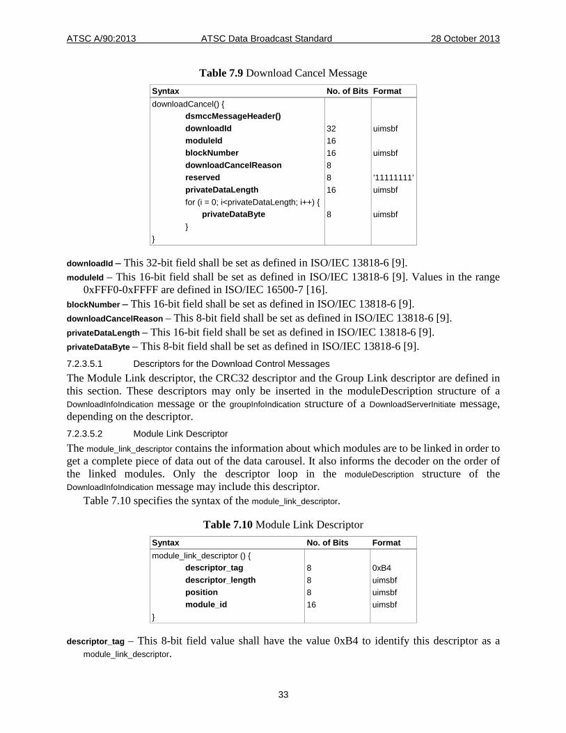
Table 7.9 Download Cancel Message Syntax No. of Bits Format downloadCancel() { dsmccMessageHeader() downloadId 32 uimsbf moduleId 16 blockNumber 16 uimsbf downloadCancelReason 8 reserved 8 ’11111111’ privateDataLength 16 uimsbf for (i = 0; i<privateDataLength; i++) { privateDataByte 8 uimsbf } }
downloadId – This 32-bit field shall be set as defined in ISO/IEC 13818-6 [9]. moduleId – This 16-bit field shall be set as defined in ISO/IEC 13818-6 [9]. Values in the range
0xFFF0-0xFFFF are defined in ISO/IEC 16500-7 [16]. blockNumber – This 16-bit field shall be set as defined in ISO/IEC 13818-6 [9]. downloadCancelReason – This 8-bit field shall be set as defined in ISO/IEC 13818-6 [9]. privateDataLength – This 16-bit field shall be set as defined in ISO/IEC 13818-6 [9]. privateDataByte – This 8-bit field shall be set as defined in ISO/IEC 13818-6 [9]. 7.2.3.5.1 Descriptors for the Download Control Messages The Module Link descriptor, the CRC32 descriptor and the Group Link descriptor are defined in this section. These descriptors may only be inserted in the moduleDescription structure of a DownloadInfoIndication message or the groupInfoIndication structure of a DownloadServerInitiate message, depending on the descriptor. 7.2.3.5.2 Module Link Descriptor The module_link_descriptor contains the information about which modules are to be linked in order to get a complete piece of data out of the data carousel. It also informs the decoder on the order of the linked modules. Only the descriptor loop in the moduleDescription structure of the DownloadInfoIndication message may include this descriptor.
Table 7.10 specifies the syntax of the module_link_descriptor.
Table 7.10 Module Link Descriptor Syntax No. of Bits Format module_link_descriptor () { descriptor_tag 8 0xB4 descriptor_length 8 uimsbf position 8 uimsbf module_id 16 uimsbf }
descriptor_tag – This 8-bit field value shall have the value 0xB4 to identify this descriptor as a module_link_descriptor.
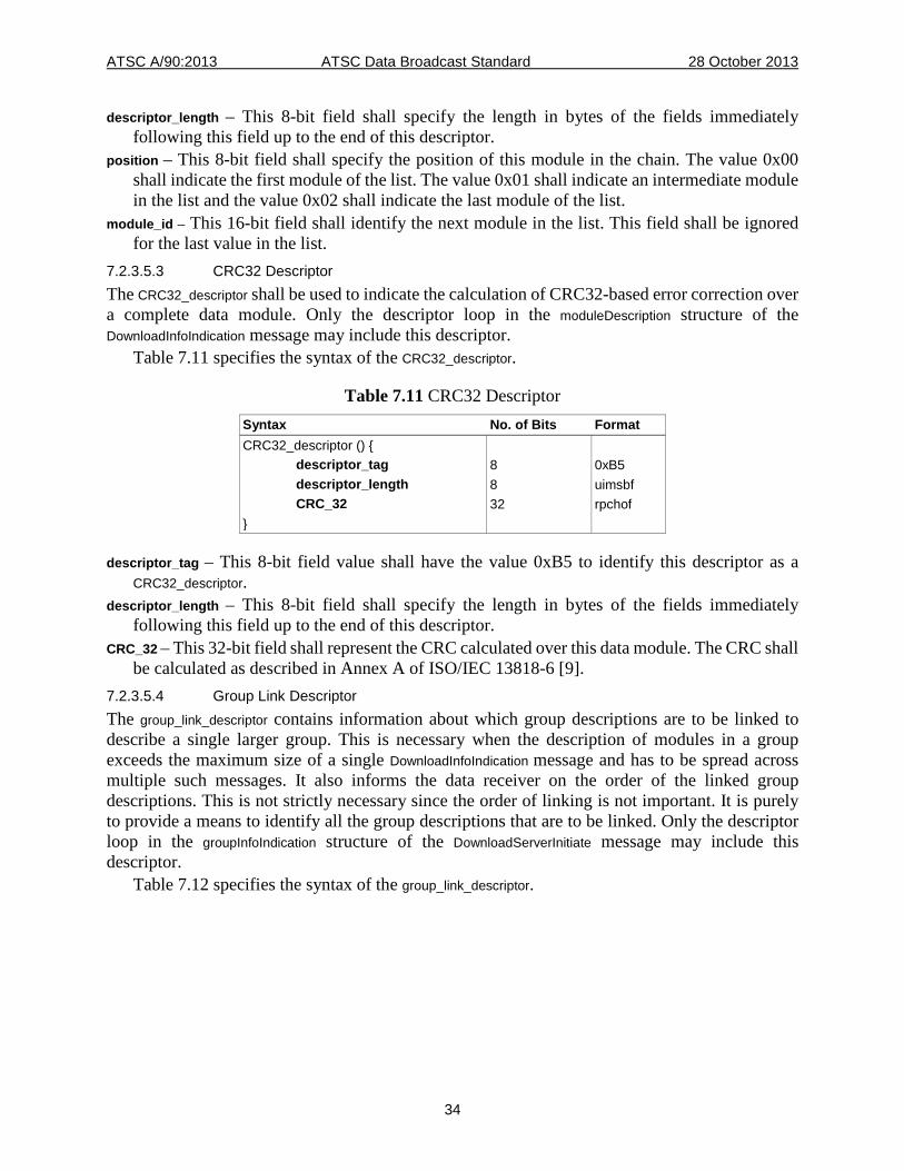
ATSC A/90:2013 ATSC Data Broadcast Standard 28 October 2013
34
descriptor_length – This 8-bit field shall specify the length in bytes of the fields immediately following this field up to the end of this descriptor.
position – This 8-bit field shall specify the position of this module in the chain. The value 0x00 shall indicate the first module of the list. The value 0x01 shall indicate an intermediate module in the list and the value 0x02 shall indicate the last module of the list.
module_id – This 16-bit field shall identify the next module in the list. This field shall be ignored for the last value in the list.
7.2.3.5.3 CRC32 Descriptor The CRC32_descriptor shall be used to indicate the calculation of CRC32-based error correction over a complete data module. Only the descriptor loop in the moduleDescription structure of the DownloadInfoIndication message may include this descriptor.
Table 7.11 specifies the syntax of the CRC32_descriptor.
Table 7.11 CRC32 Descriptor Syntax No. of Bits Format CRC32_descriptor () { descriptor_tag 8 0xB5 descriptor_length 8 uimsbf CRC_32 32 rpchof }
descriptor_tag – This 8-bit field value shall have the value 0xB5 to identify this descriptor as a CRC32_descriptor.
descriptor_length – This 8-bit field shall specify the length in bytes of the fields immediately following this field up to the end of this descriptor.
CRC_32 – This 32-bit field shall represent the CRC calculated over this data module. The CRC shall be calculated as described in Annex A of ISO/IEC 13818-6 [9].
7.2.3.5.4 Group Link Descriptor The group_link_descriptor contains information about which group descriptions are to be linked to describe a single larger group. This is necessary when the description of modules in a group exceeds the maximum size of a single DownloadInfoIndication message and has to be spread across multiple such messages. It also informs the data receiver on the order of the linked group descriptions. This is not strictly necessary since the order of linking is not important. It is purely to provide a means to identify all the group descriptions that are to be linked. Only the descriptor loop in the groupInfoIndication structure of the DownloadServerInitiate message may include this descriptor.
Table 7.12 specifies the syntax of the group_link_descriptor.
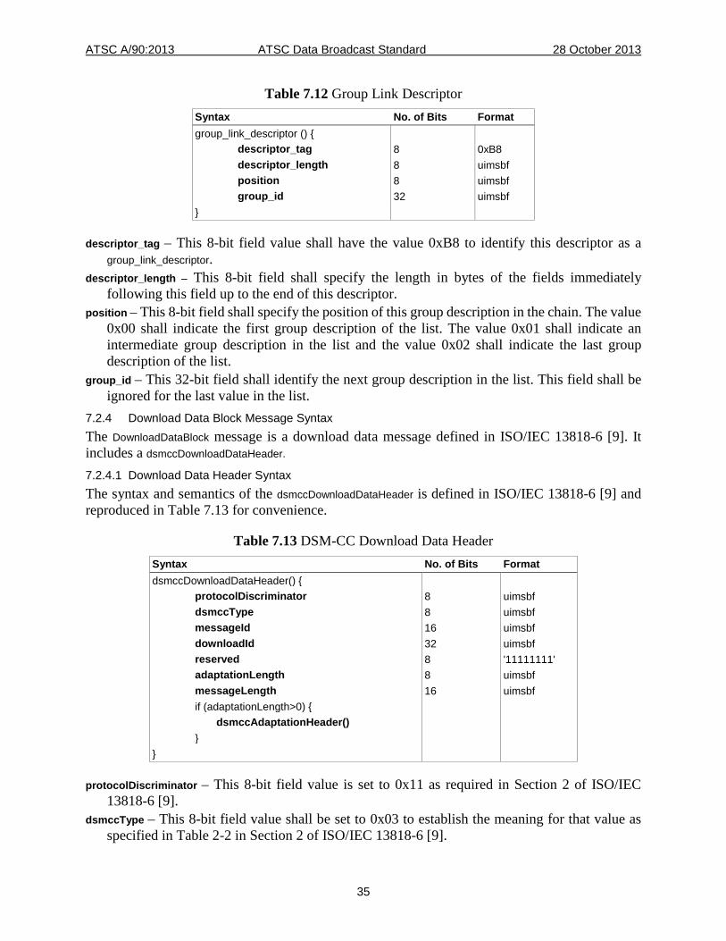
ATSC A/90:2013 ATSC Data Broadcast Standard 28 October 2013
35
Table 7.12 Group Link Descriptor Syntax No. of Bits Format group_link_descriptor () { descriptor_tag 8 0xB8 descriptor_length 8 uimsbf position 8 uimsbf group_id 32 uimsbf }
descriptor_tag – This 8-bit field value shall have the value 0xB8 to identify this descriptor as a group_link_descriptor.
descriptor_length – This 8-bit field shall specify the length in bytes of the fields immediately following this field up to the end of this descriptor.
position – This 8-bit field shall specify the position of this group description in the chain. The value 0x00 shall indicate the first group description of the list. The value 0x01 shall indicate an intermediate group description in the list and the value 0x02 shall indicate the last group description of the list.
group_id – This 32-bit field shall identify the next group description in the list. This field shall be ignored for the last value in the list.
7.2.4 Download Data Block Message Syntax The DownloadDataBlock message is a download data message defined in ISO/IEC 13818-6 [9]. It includes a dsmccDownloadDataHeader.
7.2.4.1 Download Data Header Syntax The syntax and semantics of the dsmccDownloadDataHeader is defined in ISO/IEC 13818-6 [9] and reproduced in Table 7.13 for convenience.
Table 7.13 DSM-CC Download Data Header Syntax No. of Bits Format dsmccDownloadDataHeader() { protocolDiscriminator 8 uimsbf dsmccType 8 uimsbf messageId 16 uimsbf downloadId 32 uimsbf reserved 8 '11111111' adaptationLength 8 uimsbf messageLength 16 uimsbf if (adaptationLength>0) { dsmccAdaptationHeader() } }
protocolDiscriminator – This 8-bit field value is set to 0x11 as required in Section 2 of ISO/IEC 13818-6 [9].
dsmccType – This 8-bit field value shall be set to 0x03 to establish the meaning for that value as specified in Table 2-2 in Section 2 of ISO/IEC 13818-6 [9].
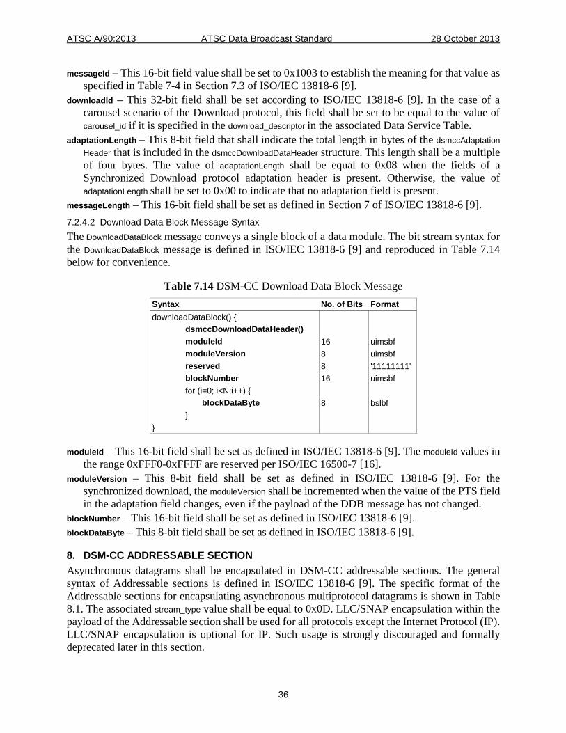
ATSC A/90:2013 ATSC Data Broadcast Standard 28 October 2013
36
messageId – This 16-bit field value shall be set to 0x1003 to establish the meaning for that value as specified in Table 7-4 in Section 7.3 of ISO/IEC 13818-6 [9].
downloadId – This 32-bit field shall be set according to ISO/IEC 13818-6 [9]. In the case of a carousel scenario of the Download protocol, this field shall be set to be equal to the value of carousel_id if it is specified in the download_descriptor in the associated Data Service Table.
adaptationLength – This 8-bit field that shall indicate the total length in bytes of the dsmccAdaptation Header that is included in the dsmccDownloadDataHeader structure. This length shall be a multiple of four bytes. The value of adaptationLength shall be equal to 0x08 when the fields of a Synchronized Download protocol adaptation header is present. Otherwise, the value of adaptationLength shall be set to 0x00 to indicate that no adaptation field is present.
messageLength – This 16-bit field shall be set as defined in Section 7 of ISO/IEC 13818-6 [9]. 7.2.4.2 Download Data Block Message Syntax The DownloadDataBlock message conveys a single block of a data module. The bit stream syntax for the DownloadDataBlock message is defined in ISO/IEC 13818-6 [9] and reproduced in Table 7.14 below for convenience.
Table 7.14 DSM-CC Download Data Block Message Syntax No. of Bits Format downloadDataBlock() { dsmccDownloadDataHeader() moduleId 16 uimsbf moduleVersion 8 uimsbf reserved 8 '11111111' blockNumber 16 uimsbf for (i=0; i<N;i++) { blockDataByte 8 bslbf } }
moduleId – This 16-bit field shall be set as defined in ISO/IEC 13818-6 [9]. The moduleId values in the range 0xFFF0-0xFFFF are reserved per ISO/IEC 16500-7 [16].
moduleVersion – This 8-bit field shall be set as defined in ISO/IEC 13818-6 [9]. For the synchronized download, the moduleVersion shall be incremented when the value of the PTS field in the adaptation field changes, even if the payload of the DDB message has not changed.
blockNumber – This 16-bit field shall be set as defined in ISO/IEC 13818-6 [9]. blockDataByte – This 8-bit field shall be set as defined in ISO/IEC 13818-6 [9].
8. DSM-CC ADDRESSABLE SECTION Asynchronous datagrams shall be encapsulated in DSM-CC addressable sections. The general syntax of Addressable sections is defined in ISO/IEC 13818-6 [9]. The specific format of the Addressable sections for encapsulating asynchronous multiprotocol datagrams is shown in Table 8.1. The associated stream_type value shall be equal to 0x0D. LLC/SNAP encapsulation within the payload of the Addressable section shall be used for all protocols except the Internet Protocol (IP). LLC/SNAP encapsulation is optional for IP. Such usage is strongly discouraged and formally deprecated later in this section.
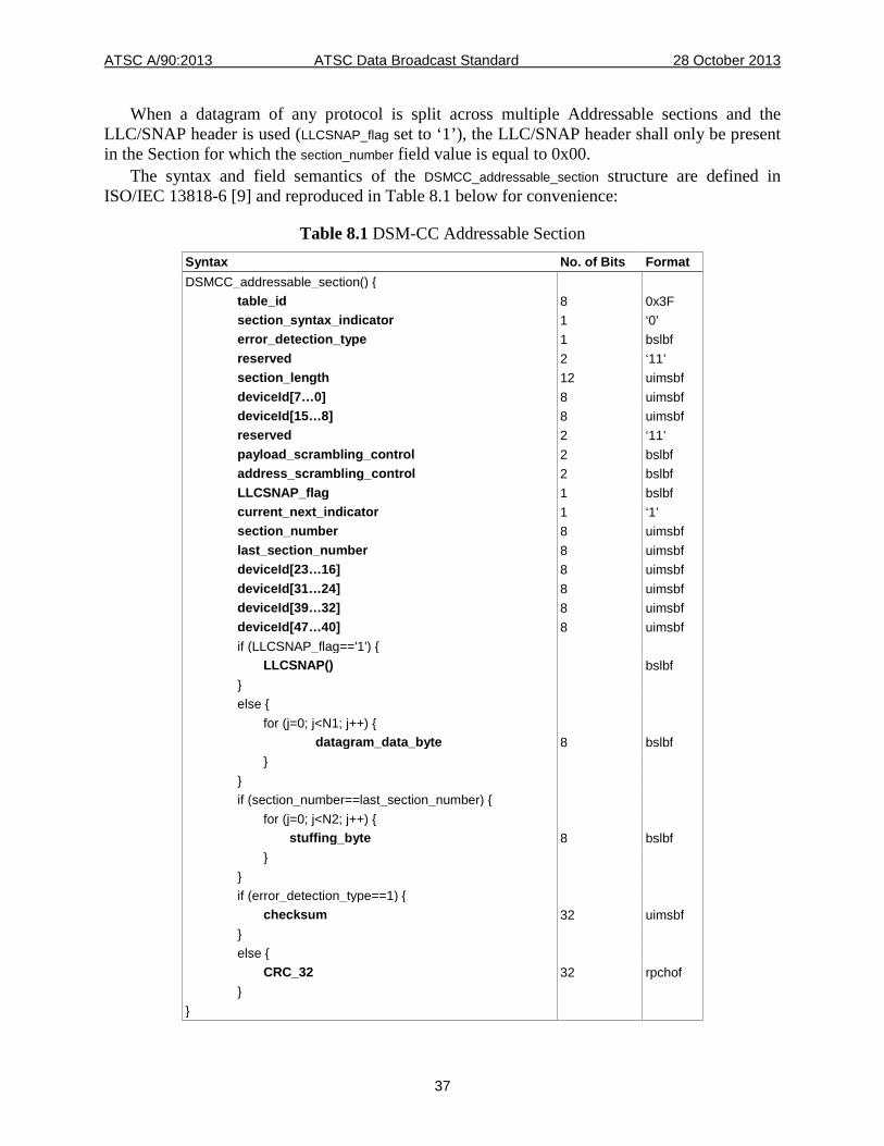
ATSC A/90:2013 ATSC Data Broadcast Standard 28 October 2013
37
When a datagram of any protocol is split across multiple Addressable sections and the LLC/SNAP header is used (LLCSNAP_flag set to ‘1’), the LLC/SNAP header shall only be present in the Section for which the section_number field value is equal to 0x00.
The syntax and field semantics of the DSMCC_addressable_section structure are defined in ISO/IEC 13818-6 [9] and reproduced in Table 8.1 below for convenience:
Table 8.1 DSM-CC Addressable Section Syntax No. of Bits Format DSMCC_addressable_section() { table_id 8 0x3F section_syntax_indicator 1 ‘0’ error_detection_type 1 bslbf reserved 2 ‘11’ section_length 12 uimsbf deviceId[7…0] 8 uimsbf deviceId[15…8] 8 uimsbf reserved 2 ‘11’ payload_scrambling_control 2 bslbf address_scrambling_control 2 bslbf LLCSNAP_flag 1 bslbf current_next_indicator 1 ‘1’ section_number 8 uimsbf last_section_number 8 uimsbf deviceId[23…16] 8 uimsbf deviceId[31…24] 8 uimsbf deviceId[39…32] 8 uimsbf deviceId[47…40] 8 uimsbf if (LLCSNAP_flag=='1') { LLCSNAP() bslbf } else { for (j=0; j<N1; j++) { datagram_data_byte 8 bslbf } } if (section_number==last_section_number) { for (j=0; j<N2; j++) { stuffing_byte 8 bslbf } } if (error_detection_type==1) { checksum 32 uimsbf } else { CRC_32 32 rpchof } }
ATSC A/90:2013 ATSC Data Broadcast Standard 28 October 2013
38
The semantics of the DSMCC_addressable_section fields are as follows: table_id – This 8-bit field shall be set as defined in ISO/IEC 13818-6 [9]. section_syntax_indicator – This 1-bit field shall be set as defined in ISO/IEC 13818-6 [9]. error_detection_type – This 1-bit field shall be set as defined in ISO/IEC 13818-6 [9]. reserved – This 2-bit field shall be set as defined in ISO/IEC 13818-6 [9]. section_length – This 12-bit field shall be set as defined in ISO/IEC 13818-6 [9]. deviceId – This 48-bit field shall identify the intended receiver device. The deviceId field shall be
reconstructed from the in order concatenation of the deviceId[47…40], deviceId[39…32], deviceId[31…24], deviceId[23…16], deviceId[15…8] and deviceId[7…0] fields, representing bit number 47 to 40, bit number 39 to 32, bit number 31 to 24, bit number 23 to 16, bit number 15 to 8, bit number 7 to 0, respectively. Note that the order of the bits in the bytes is not reversed and that the most significant bit of each byte of deviceId is still transmitted first.
payload_scrambling_control – This 2-bit field shall be set as defined in ISO/IEC 13818-6 [9]. address_scrambling_control – This 2 bit field shall be set as defined in ISO/IEC 13818-6 [9]. LLCSNAP_flag – This 1-bit field shall be set as defined in ISO/IEC 13818-6 [9]. When
protocol_encapsulation (defined in section 12.2.1 of this standard) is equal to 0x03, this flag shall be set to 1. When protocol_encapsulation field is equal to 0x04, this flag shall be set to 0.
current_next_indicator – This 1-bit field shall be set as defined in ISO/IEC 13818-6 [9]. section_number – This 8-bit field shall be set as defined in ISO/IEC 13818-6 [9]. last_section_number – This 8-bit shall be set as defined in ISO/IEC 13818-6 [9]. LLCSNAP() – This structure shall be set as defined in ISO/IEC 13818-6 [9]. datagram_data_byte – This 8-bit field shall be defined as in ISO/IEC 13818-6 [9]. This can be a
datagram header byte or a datagram payload byte. stuffing_byte – This 8-bit field shall be set as defined in ISO/IEC 13818-6 [9]. checksum – A 32 bit checksum calculated over the entire DSMCC_addressable_section. The checksum
shall be calculated by treating the DSMCC_addressable_section as a sequence of 32-bit integers and performing one’s complement addition over all the integers, most significant byte first, then taking the one’s complement of the result. For the purpose of computing the checksum, the value of the checksum field shall be considered ‘0’. If the message length is not a multiple of four bytes, the message shall be considered to be appended with zeroed bytes for the purpose of checksum calculation only. If the computed result is ‘0’, then the result shall be set to 0xFFFFFFFF (the alternative value for a one’s complement representation of ‘0’). In cases where a checksum is not desired, the value of this field shall be set to ‘0’ to indicate the checksum has not been calculated. This feature is useful for networks where error detection is provided at a protocol layer lower than the MPEG-2 Transport Stream.
CRC_32 – This 32 bit field shall be set as defined in ISO/IEC 13818-6 [9].
8.1 Encapsulation Rules in DSM-CC Addressable Sections Datagrams shall never be split across Sections. Therefore, the value of the section_number and last_section_number fields of the DSMCC_addressable_section Section shall always be equal to ‘0’. LLC/SNAP encapsulation is optional for IP packets but deprecated. The Maximum Transmission Unit (MTU) for IP shall be 4080 bytes if not encapsulated in LLC/SNAP. The Maximum Transmission Unit shall be 4072 bytes if LLC/SNAP is employed. Only one datagram shall be included in any one DSMCC_addressable_section.
ATSC A/90:2013 ATSC Data Broadcast Standard 28 October 2013
39
9. SYNCHRONOUS AND SYNCHRONIZED STREAMING DATA Streaming synchronous and streaming synchronized data services shall use PES packetization.
Synchronous data streaming shall mean the streaming of data with timing requirements such that the data and clock can be regenerated at the receiver into a synchronous data stream. Synchronous data streams shall be carried in PES packets. Furthermore, the header of such PES packets shall always include a 33-bit PTS field. Synchronous does not imply a timing association with other data streams.
Synchronized data streams shall be carried in PES packets. Furthermore, data classified as synchronized streaming shall have a strong timing association with another PES stream or streams referenced by one or more different PIDs.
For an MPEG-2 Program including at least one streaming synchronous or streaming synchronized data elementary stream, a valid PCR_PID value shall be specified in the Program Map Table in which the program is listed and in particular, the PCR_PID value shall not be equal to 0x1FFF. Furthermore, as required in Section 2.7.2 of ISO/IEC 13818-1 [8], the time interval between successive occurrences of the PCR base field in Transport Stream packets of the Program element referenced by the PID value PCR_PID is less than or equal to 100 milliseconds. The same PCR_PID value shall appear in the Service Location Descriptor of the virtual channel that includes the streaming synchronous or the streaming synchronized data elementary stream.
The value of the stream_type field of ISO/IEC 13818-1 [8] associated with synchronous data elementary streams shall be equal to 0xC2. The value of the stream_type field of ISO/IEC 13818-1 [8] associated with synchronized data elementary streams shall be equal to 0x06.
The synchronous and synchronized data streaming specifications shall use the standard PES packet syntax and semantics as defined in ISO/IEC 13818-1 [8] with the following constraints:
• stream_id – this 8-bit field defined in ISO/IEC 13818-1 [8] shall be set to 0xBD (private_stream_1).
• PES_packet_length – this 16-bit field defined in ISO/IEC 13818-1 [8] shall be set to a non-zero value.
Synchronous or synchronized multiprotocol datagrams shall be carried in PES packets. LLC/SNAP encapsulation within the payload of PES packets shall be used for all protocols except the Internet Protocol (IP). LLC/SNAP encapsulation is optional for IP packets but deprecated.
All data payload types in synchronous or synchronized data elementary streams, including multiprotocol datagrams, shall follow the streaming rules mentioned above.
9.1 Synchronous Data Bitstream Syntax The PES payload shall follow the PES header as specified in ISO/IEC 13818-1 [8]. The PES payload shall begin with a synchronous_data_header structure followed by the synchronous data payload carried in the synchronous_data_sequence structure of SCTE 19 [11]. The synchronous data header shall always be present and the PES header shall always include a valid PTS field. The value of the PTS field shall represent the time of removal from Bn (see SCTE 19 [11], Section 5) of the first 16 bit synchronous data access unit in the PES payload. The first byte of the synchronous_data_header shall immediately follow the last byte of the PES header. The first byte of the synchronous_data_sequence structure shall immediately follow the last byte of the synchronous_data_header structure. The first payload byte in a synchronous_data_sequence shall be the first byte of a synchronous_data_access_unit (following any adaptation, PES header, and synchronous_data_header fields), and the last byte of a PES packet carrying a synchronous_data_sequence
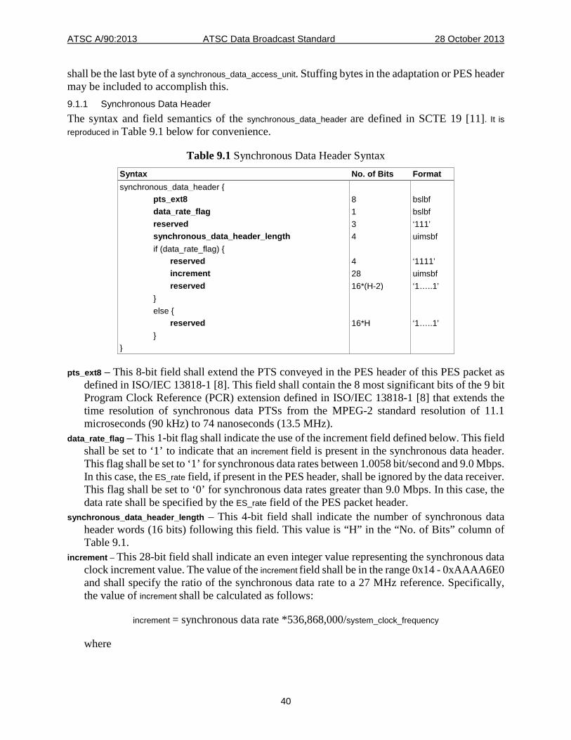
ATSC A/90:2013 ATSC Data Broadcast Standard 28 October 2013
40
shall be the last byte of a synchronous_data_access_unit. Stuffing bytes in the adaptation or PES header may be included to accomplish this. 9.1.1 Synchronous Data Header The syntax and field semantics of the synchronous_data_header are defined in SCTE 19 [11]. It is reproduced in Table 9.1 below for convenience.
Table 9.1 Synchronous Data Header Syntax Syntax No. of Bits Format synchronous_data_header { pts_ext8 8 bslbf data_rate_flag 1 bslbf reserved 3 ‘111’ synchronous_data_header_length 4 uimsbf if (data_rate_flag) { reserved 4 ‘1111’ increment 28 uimsbf reserved 16*(H-2) ‘1…..1’ } else { reserved 16*H ‘1…..1’ } }
pts_ext8 – This 8-bit field shall extend the PTS conveyed in the PES header of this PES packet as defined in ISO/IEC 13818-1 [8]. This field shall contain the 8 most significant bits of the 9 bit Program Clock Reference (PCR) extension defined in ISO/IEC 13818-1 [8] that extends the time resolution of synchronous data PTSs from the MPEG-2 standard resolution of 11.1 microseconds (90 kHz) to 74 nanoseconds (13.5 MHz).
data_rate_flag – This 1-bit flag shall indicate the use of the increment field defined below. This field shall be set to ‘1’ to indicate that an increment field is present in the synchronous data header. This flag shall be set to ‘1’ for synchronous data rates between 1.0058 bit/second and 9.0 Mbps. In this case, the ES_rate field, if present in the PES header, shall be ignored by the data receiver. This flag shall be set to ‘0’ for synchronous data rates greater than 9.0 Mbps. In this case, the data rate shall be specified by the ES_rate field of the PES packet header.
synchronous_data_header_length – This 4-bit field shall indicate the number of synchronous data header words (16 bits) following this field. This value is “H” in the “No. of Bits” column of Table 9.1.
increment – This 28-bit field shall indicate an even integer value representing the synchronous data clock increment value. The value of the increment field shall be in the range 0x14 - 0xAAAA6E0 and shall specify the ratio of the synchronous data rate to a 27 MHz reference. Specifically, the value of increment shall be calculated as follows:
increment = synchronous data rate *536,868,000/system_clock_frequency
where
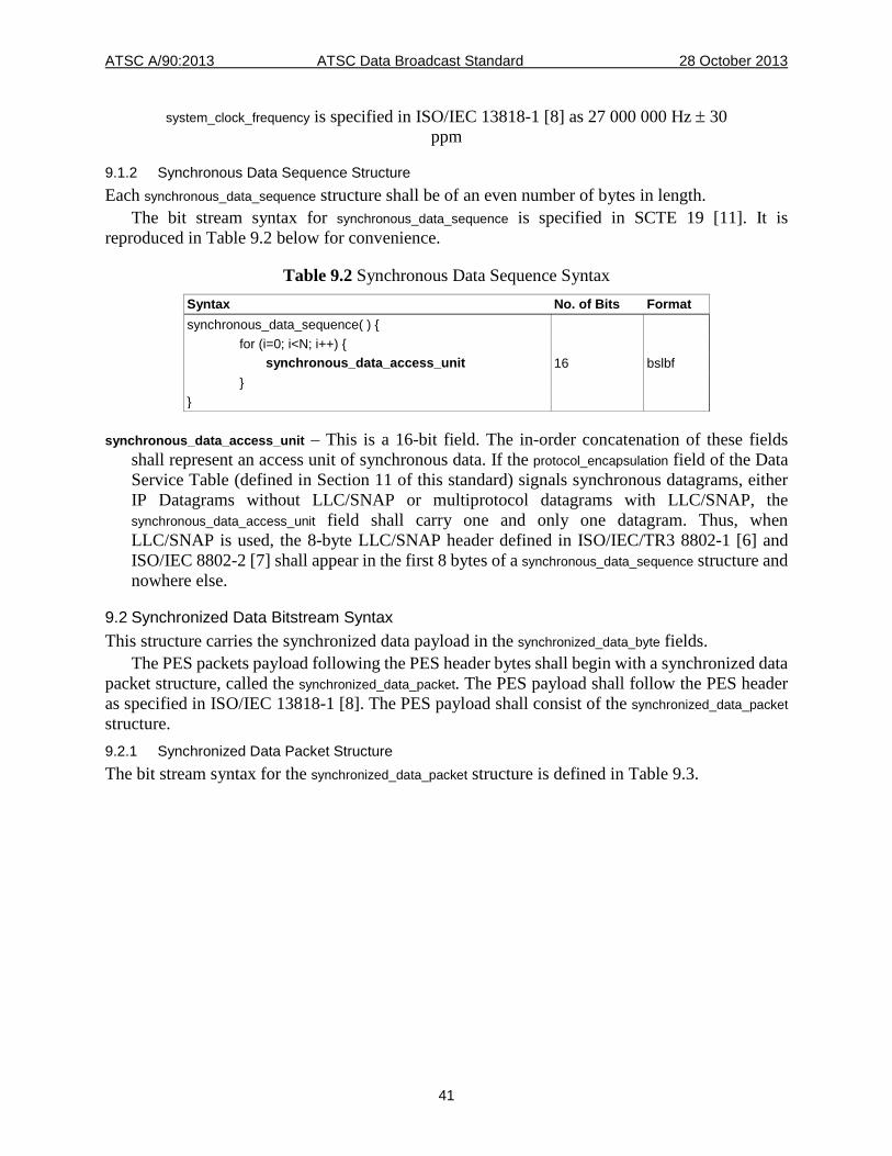
ATSC A/90:2013 ATSC Data Broadcast Standard 28 October 2013
41
system_clock_frequency is specified in ISO/IEC 13818-1 [8] as 27 000 000 Hz ± 30 ppm
9.1.2 Synchronous Data Sequence Structure Each synchronous_data_sequence structure shall be of an even number of bytes in length.
The bit stream syntax for synchronous_data_sequence is specified in SCTE 19 [11]. It is reproduced in Table 9.2 below for convenience.
Table 9.2 Synchronous Data Sequence Syntax Syntax No. of Bits Format synchronous_data_sequence( ) { for (i=0; i<N; i++) { synchronous_data_access_unit 16 bslbf } }
synchronous_data_access_unit – This is a 16-bit field. The in-order concatenation of these fields shall represent an access unit of synchronous data. If the protocol_encapsulation field of the Data Service Table (defined in Section 11 of this standard) signals synchronous datagrams, either IP Datagrams without LLC/SNAP or multiprotocol datagrams with LLC/SNAP, the synchronous_data_access_unit field shall carry one and only one datagram. Thus, when LLC/SNAP is used, the 8-byte LLC/SNAP header defined in ISO/IEC/TR3 8802-1 [6] and ISO/IEC 8802-2 [7] shall appear in the first 8 bytes of a synchronous_data_sequence structure and nowhere else.
9.2 Synchronized Data Bitstream Syntax This structure carries the synchronized data payload in the synchronized_data_byte fields.
The PES packets payload following the PES header bytes shall begin with a synchronized data packet structure, called the synchronized_data_packet. The PES payload shall follow the PES header as specified in ISO/IEC 13818-1 [8]. The PES payload shall consist of the synchronized_data_packet structure. 9.2.1 Synchronized Data Packet Structure The bit stream syntax for the synchronized_data_packet structure is defined in Table 9.3.
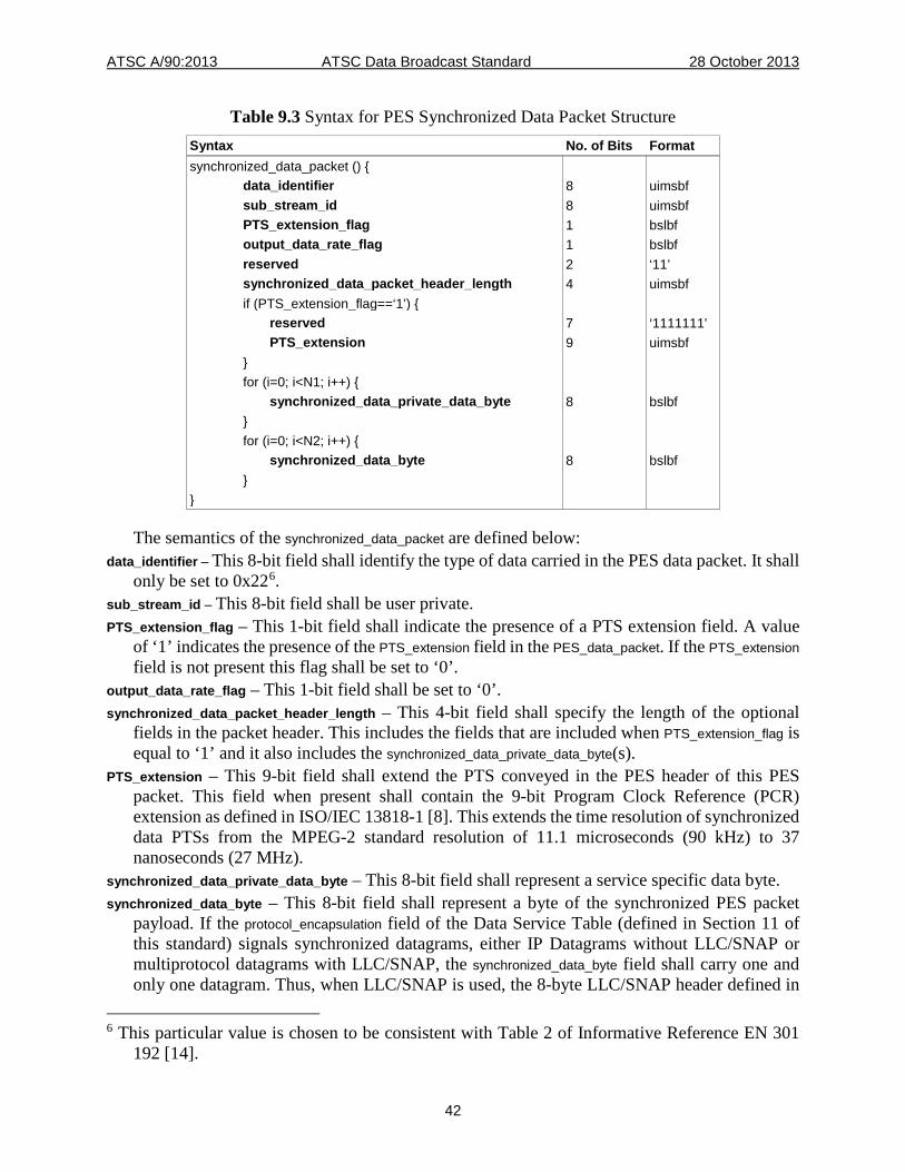
ATSC A/90:2013 ATSC Data Broadcast Standard 28 October 2013
42
Table 9.3 Syntax for PES Synchronized Data Packet Structure Syntax No. of Bits Format synchronized_data_packet () { data_identifier 8 uimsbf sub_stream_id 8 uimsbf PTS_extension_flag 1 bslbf output_data_rate_flag 1 bslbf reserved 2 ‘11’ synchronized_data_packet_header_length 4 uimsbf if (PTS_extension_flag==‘1’) { reserved 7 ‘1111111’ PTS_extension 9 uimsbf } for (i=0; i<N1; i++) { synchronized_data_private_data_byte 8 bslbf } for (i=0; i<N2; i++) { synchronized_data_byte 8 bslbf } }
The semantics of the synchronized_data_packet are defined below: data_identifier – This 8-bit field shall identify the type of data carried in the PES data packet. It shall
only be set to 0x226. sub_stream_id – This 8-bit field shall be user private. PTS_extension_flag – This 1-bit field shall indicate the presence of a PTS extension field. A value
of ‘1’ indicates the presence of the PTS_extension field in the PES_data_packet. If the PTS_extension field is not present this flag shall be set to ‘0’.
output_data_rate_flag – This 1-bit field shall be set to ‘0’. synchronized_data_packet_header_length – This 4-bit field shall specify the length of the optional
fields in the packet header. This includes the fields that are included when PTS_extension_flag is equal to ‘1’ and it also includes the synchronized_data_private_data_byte(s).
PTS_extension – This 9-bit field shall extend the PTS conveyed in the PES header of this PES packet. This field when present shall contain the 9-bit Program Clock Reference (PCR) extension as defined in ISO/IEC 13818-1 [8]. This extends the time resolution of synchronized data PTSs from the MPEG-2 standard resolution of 11.1 microseconds (90 kHz) to 37 nanoseconds (27 MHz).
synchronized_data_private_data_byte – This 8-bit field shall represent a service specific data byte. synchronized_data_byte – This 8-bit field shall represent a byte of the synchronized PES packet
payload. If the protocol_encapsulation field of the Data Service Table (defined in Section 11 of this standard) signals synchronized datagrams, either IP Datagrams without LLC/SNAP or multiprotocol datagrams with LLC/SNAP, the synchronized_data_byte field shall carry one and only one datagram. Thus, when LLC/SNAP is used, the 8-byte LLC/SNAP header defined in
6 This particular value is chosen to be consistent with Table 2 of Informative Reference EN 301
192 [14].
ATSC A/90:2013 ATSC Data Broadcast Standard 28 October 2013
43
ISO/IEC/TR3 8802-1 [6] and ISO/IEC 8802-2 [7] shall appear in the first 8 synchronized_data_byte bytes of a PES packet and nowhere else.
9.3 Datagram Encapsulation The synchronous_data_sequence (synchronous data elementary stream) or the synchronized_data_byte (synchronized data elementary stream) field definition allows for the tunneling of Internet Protocol (IP) datagrams with or without an LLC/SNAP header. Tunneling of IP Datagrams without any LLC/SNAP is recommended and tunneling of IP Datagrams with a LCC/SNAP header is deprecated. The IP Maximum Transmission Unit (MTU) shall be 4080 bytes if not encapsulated in LLC/SNAP, and 4072 bytes if LLC/SNAP is employed. A PES packet shall not include more than one IP Datagram whether the LLC/SNAP header is present or not. The absence or presence of the LLC/SNAP header shall be signaled in the protocol_encapsulation field defined in Table 12.5 of Section 12.
10. DATA PIPING This data broadcast standard defines data piping as a mechanism for delivery of arbitrary user-defined data inside an MPEG-2 transport stream. Data is inserted directly into the payload of MPEG-2 transport stream packets, and none of the Sections, tables or PES data structures defined in this standard are required. In other words, no methods are specified in this standard for fragmentation or re-assembly of data sent in this manner, and all interpretation of the data bits shall be application defined. However, the Service Description Framework information shall be provided as defined in Section 12 of this standard. Likewise, announcement and scheduling of data piping-based data services shall comply with requirements in Section 11 of this standard. When Data Piping is used an MRD per ISO/IEC 13818-1 [8] shall be placed in the descriptor() field after the tap_info_length field in the DST. Any use of the adaptation fields in Transport Stream packets shall be compliant with ISO/IEC 13818-1 [8].
11. DATA SERVICE ANNOUNCEMENT REQUIREMENTS
11.1 Introduction Program and System Information Protocol (PSIP), specified in A/65 [3], is a collection of hierarchically arranged tables for describing system information and program guide data. This standard utilizes and builds upon the PSIP Standard to select data services in the broadcast stream. This standard defines extensions to A/65 [3].
The schedule of a Data Service of service type value 0x04 shall not be announced as a separate event in an EIT-n; however, there shall be a data_service_descriptor presentif there is any Data Service associated with an Event in an EIT-n; see A/65 [3].
11.2 Virtual Channels Each virtual channel in a PSIP Virtual Channel Table (VCT)7 shall include no more than one data service. Consequently, there shall be no more than one data elementary stream of stream_type value 0x95 (Service Description Framework information) listed in each virtual channel's Service Location Descriptor in the VCT. Furthermore, there shall be no more than one data elementary
7 The VCT is a more general term that includes either the TCVT or the CVCT as defined in A/65
[3].
ATSC A/90:2013 ATSC Data Broadcast Standard 28 October 2013
44
stream of stream_type value 0x95 (Service Description Framework information) listed in a TS_program_map_section (instance of a Program Map Table) as defined in ISO/IEC 13818-1 [8].
The Service Location Descriptor of a virtual channel conveying a data service shall list all the data elementary streams belonging to the ISO/IEC 13818-1 Program associated with the Virtual Channel that may be used by the data service. The data service may utilize any or all of the protocol encapsulation types defined by this standard. The minor_channel_number (as defined in A/65 [3]) for services of service_type value 0x04 shall be equal to or greater than 100. Even with this constraint, up to 900 stand-alone data services per value of major virtual channel number can be present in the ATSC Transport Stream.
11.3 Data Event Table A new table, named the Data Event Table (DET) is defined hereinafter. The purpose of the DET is twofold:
• To support the announcement of a data service in a Virtual Channel (PSIP service_type field value equal to 0x04), which does not include any audio-visual event.
• To allow separate announcement of the data service portion of an audio/video/data event (PSIP service_type field value equal to 0x02) or audio/data event (PSIP service_type field value equal to 0x03) in a Virtual Channel.
When a virtual channel of service_type value 0x04 is present, the DET may be used to announce one or moredata service events in that virtual channel.
For a virtual channel of service_type 0x02 or 0x03, the data service portion of an audio/video/data event may be announced independently in a DET. The purpose of such separate announcement is:
• To convey a data service schedule that is not aligned with the associated audio/video event. In this situation, the data service schedule (start_time, duration) may span only a fraction of the audio/video portion of an event or it may span the audio/video portion of several events. The value of the source_id field in the DET(s) announcing the data portion of the event(s) shall match the value of the source_id field in the related EIT(s) where the audio/video portion of the event(s) is announced. This constraint captures the fact that the audio/video and data portions of the event(s) belong to the same virtual channel.
• To convey a distinct name or description for the data service portion of the audio/video/data event. In this situation, the data service portion of the event shares the same schedule (start_time, duration) as the audio/video portion of the event. The value of the source_id field in the DET(s) shall match the value of the source_id field in the related EIT(s) where the audio/video portion of the event is announced. This constraint captures the fact that audio/video and data portions of the event belong to the same virtual channel.
• To convey an Extended Text Table specific to the Data Service. In this situation, the data_id field in the DET allows identification of an ETT associated with the instance of the DET announcing the schedule of the data service.
• To enable realization of a data event which had originally been pre-announced earlier in an instance of a Long Term Service Table section (specified hereinafter).
The DET contains information (titles, start times, etc.) for data services on defined virtual channels for a three hour time span. Up to 128 DETs may be transmitted and each is referred to as DET-k, with k = 0, 1, … 127. The minimum required number of time segments for DET-k’s is 4. Any change in a DET-k shall trigger a change in version of the MGT.
ATSC A/90:2013 ATSC Data Broadcast Standard 28 October 2013
45
Each DET-k may have multiple instances, each of which contains information for one virtual channel, and each of which is identified by the combination of table_id and source_id. Each DET-k instance may be segmented into as many as 256 Sections. One Section may contain information for several data services, but the information for one data service shall not be segmented and put into two or more Sections. Thus the first field after protocol_version for each Section shall be num_data_in_section.
The PSIP may optionally have DETs containing data events for data services belonging to virtual channels of service_type 0x02 or 0x03. In this case, the data events in the DETs shall not duplicate information about the events announced in the EITs for those Virtual Channels. They shall announce only the data service portions of those Virtual Channels. Any data event announced for a time interval that extends over one or more DETs shall be described in each of these DETs, with the same data_id. For instance, an event that starts at 17:30 UTC and lasts until 19:30 UTC will appear in two DETs with the same data_id, the DET covering 15:00-18:00 UTC as well as the DET covering 18:00-21:00 UTC. For a particular virtual channel, a data_id identifies uniquely each of the data services for the 3-hour interval of a DET. The data_id field in DETs and event_id field in EITs shall not share the same value space.
The content_advisory_descriptor defined in A/65 [3] shall not appear in the data event descriptor loop of any DET-k's associated with a virtual channel of service_type 0x02 or 0x03.
Data events in a DET instance shall be in the order of their starting times; i.e., the start_time of the first data event in a Section shall be ahead of that of the second data event in the same Section, and the start_time of the last data event in Section one shall be ahead of that of the first data event in Section two, etc. Moreover, in any virtual channel, the start_time value of a data event shall not be less than the end time of the preceding event where the end time of an event is defined to be equal to that event's start_time plus that event's length_in_seconds value.
The Data Event Table is carried in Private Sections with table_id value 0xCE, and obeys the syntax and semantics of the Private Section as described in Section 2.4.4.10 and 2.4.4.11 of ISO/IEC 13818-1 [8]. The following constraints apply to Transport Stream packets if carrying DET sections:
• The value of the PID for DET-k shall be specified in the Master Guide Table (MGT) of A/65 [3] and shall be unique among the collection of table_type_PID values listed in the MGT
• transport_scrambling_control bits shall have the value ‘00’ • adaptation_field_control bits shall have the value ‘01’. The following constraints shall apply to the DET: • Each DET shall identify data services available on a particular virtual channel during a 3
hour time interval. • The beginning of the time interval associated with each DET shall be restricted to 00:00:00
(midnight), 3:00:00, 6:00:00, 9:00:00, 12:00:00 (noon), 15:00:00, 18:00:00 and 21:00:00. All of these times are UTC.
• DET-0 shall list all the available events for the current 3-hour time segment. DET-1 shall list all the available events for the next 3-hour time segment, and likewise, non-overlapping sequential time windows are allocated for all the other DET-k’s.
• Every digital Transport Stream where DETs are required shall broadcast the first four Data Event Tables (DET-0, DET-1, DET-2 and DET-3). All the other DETs and the whole collection of associated ETTs are optional.
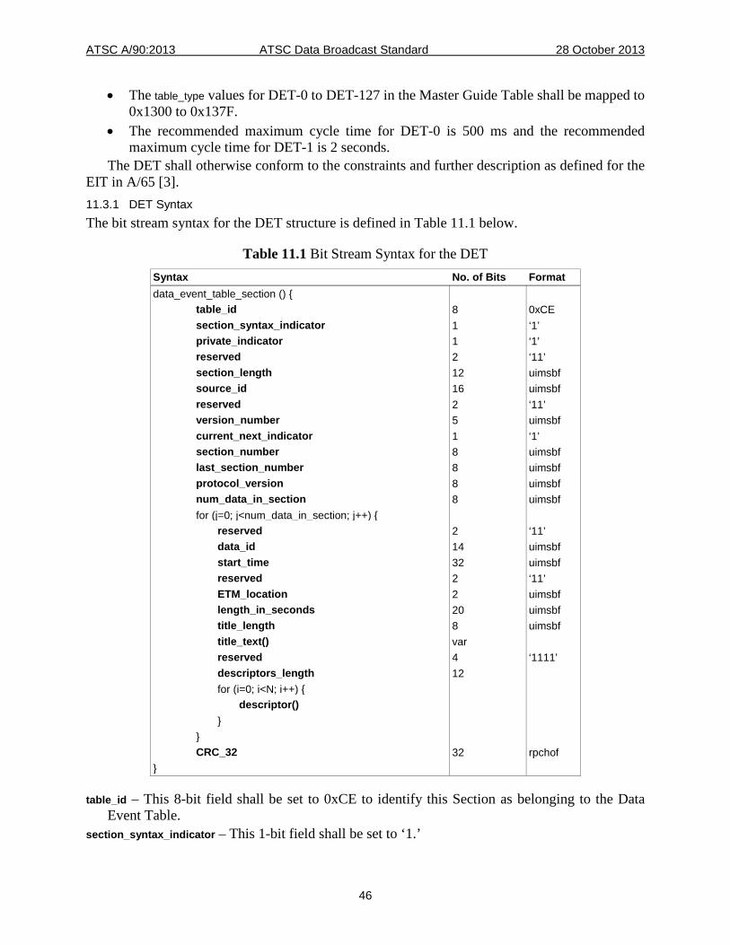
ATSC A/90:2013 ATSC Data Broadcast Standard 28 October 2013
46
• The table_type values for DET-0 to DET-127 in the Master Guide Table shall be mapped to 0x1300 to 0x137F.
• The recommended maximum cycle time for DET-0 is 500 ms and the recommended maximum cycle time for DET-1 is 2 seconds.
The DET shall otherwise conform to the constraints and further description as defined for the EIT in A/65 [3]. 11.3.1 DET Syntax The bit stream syntax for the DET structure is defined in Table 11.1 below.
Table 11.1 Bit Stream Syntax for the DET Syntax No. of Bits Format data_event_table_section () { table_id 8 0xCE section_syntax_indicator 1 ‘1’ private_indicator 1 ‘1’ reserved 2 ‘11’ section_length 12 uimsbf source_id 16 uimsbf reserved 2 ‘11’ version_number 5 uimsbf current_next_indicator 1 ‘1’ section_number 8 uimsbf last_section_number 8 uimsbf protocol_version 8 uimsbf num_data_in_section 8 uimsbf for (j=0; j<num_data_in_section; j++) { reserved 2 ‘11’ data_id 14 uimsbf start_time 32 uimsbf reserved 2 ‘11’ ETM_location 2 uimsbf length_in_seconds 20 uimsbf title_length 8 uimsbf title_text() var reserved 4 ‘1111’ descriptors_length 12 for (i=0; i<N; i++) { descriptor() } } CRC_32 32 rpchof }
table_id – This 8-bit field shall be set to 0xCE to identify this Section as belonging to the Data Event Table.
section_syntax_indicator – This 1-bit field shall be set to ‘1.’
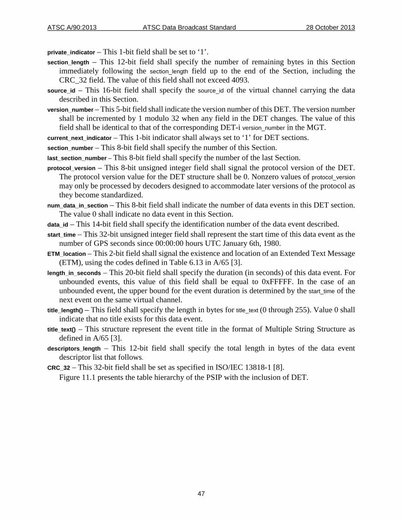
ATSC A/90:2013 ATSC Data Broadcast Standard 28 October 2013
47
private_indicator – This 1-bit field shall be set to ‘1’. section_length – This 12-bit field shall specify the number of remaining bytes in this Section
immediately following the section_length field up to the end of the Section, including the CRC_32 field. The value of this field shall not exceed 4093.
source_id – This 16-bit field shall specify the source_id of the virtual channel carrying the data described in this Section.
version_number – This 5-bit field shall indicate the version number of this DET. The version number shall be incremented by 1 modulo 32 when any field in the DET changes. The value of this field shall be identical to that of the corresponding DET-i version_number in the MGT.
current_next_indicator – This 1-bit indicator shall always set to ‘1’ for DET sections. section_number – This 8-bit field shall specify the number of this Section. last_section_number – This 8-bit field shall specify the number of the last Section. protocol_version – This 8-bit unsigned integer field shall signal the protocol version of the DET.
The protocol version value for the DET structure shall be 0. Nonzero values of protocol_version may only be processed by decoders designed to accommodate later versions of the protocol as they become standardized.
num_data_in_section – This 8-bit field shall indicate the number of data events in this DET section. The value 0 shall indicate no data event in this Section.
data_id – This 14-bit field shall specify the identification number of the data event described. start_time – This 32-bit unsigned integer field shall represent the start time of this data event as the
number of GPS seconds since 00:00:00 hours UTC January 6th, 1980. ETM_location – This 2-bit field shall signal the existence and location of an Extended Text Message
(ETM), using the codes defined in Table 6.13 in A/65 [3]. length_in_seconds – This 20-bit field shall specify the duration (in seconds) of this data event. For
unbounded events, this value of this field shall be equal to 0xFFFFF. In the case of an unbounded event, the upper bound for the event duration is determined by the start_time of the next event on the same virtual channel.
title_length() – This field shall specify the length in bytes for title_text (0 through 255). Value 0 shall indicate that no title exists for this data event.
title_text() – This structure represent the event title in the format of Multiple String Structure as defined in A/65 [3].
descriptors_length – This 12-bit field shall specify the total length in bytes of the data event descriptor list that follows.
CRC_32 – This 32-bit field shall be set as specified in ISO/IEC 13818-1 [8]. Figure 11.1 presents the table hierarchy of the PSIP with the inclusion of DET.
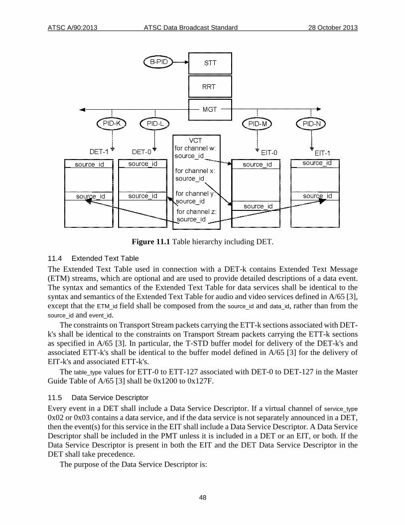
ATSC A/90:2013 ATSC Data Broadcast Standard 28 October 2013
48
Figure 11.1 Table hierarchy including DET.
11.4 Extended Text Table The Extended Text Table used in connection with a DET-k contains Extended Text Message (ETM) streams, which are optional and are used to provide detailed descriptions of a data event. The syntax and semantics of the Extended Text Table for data services shall be identical to the syntax and semantics of the Extended Text Table for audio and video services defined in A/65 [3], except that the ETM_id field shall be composed from the source_id and data_id, rather than from the source_id and event_id.
The constraints on Transport Stream packets carrying the ETT-k sections associated with DET-k's shall be identical to the constraints on Transport Stream packets carrying the ETT-k sections as specified in A/65 [3]. In particular, the T-STD buffer model for delivery of the DET-k's and associated ETT-k's shall be identical to the buffer model defined in A/65 [3] for the delivery of EIT-k's and associated ETT-k's.
The table_type values for ETT-0 to ETT-127 associated with DET-0 to DET-127 in the Master Guide Table of A/65 [3] shall be 0x1200 to 0x127F.
11.5 Data Service Descriptor Every event in a DET shall include a Data Service Descriptor. If a virtual channel of service_type 0x02 or 0x03 contains a data service, and if the data service is not separately announced in a DET, then the event(s) for this service in the EIT shall include a Data Service Descriptor. A Data Service Descriptor shall be included in the PMT unless it is included in a DET or an EIT, or both. If the Data Service Descriptor is present in both the EIT and the DET Data Service Descriptor in the DET shall take precedence.
The purpose of the Data Service Descriptor is:
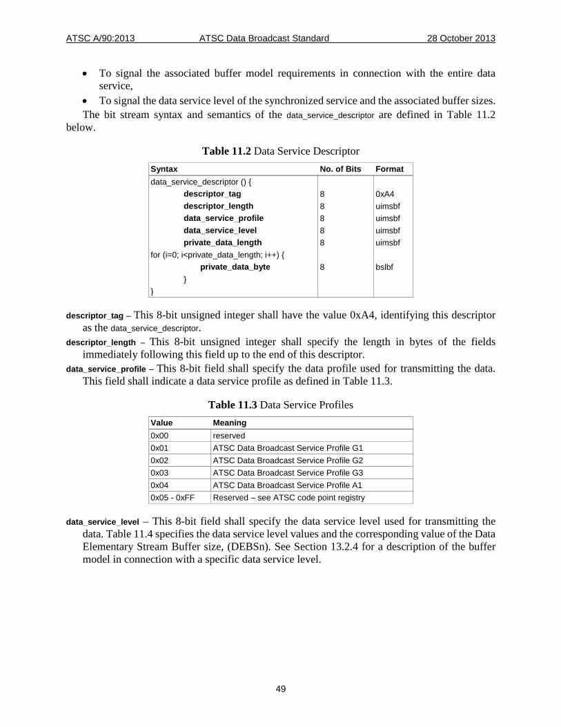
ATSC A/90:2013 ATSC Data Broadcast Standard 28 October 2013
49
• To signal the associated buffer model requirements in connection with the entire data service,
• To signal the data service level of the synchronized service and the associated buffer sizes. The bit stream syntax and semantics of the data_service_descriptor are defined in Table 11.2
below.
Table 11.2 Data Service Descriptor Syntax No. of Bits Format data_service_descriptor () { descriptor_tag 8 0xA4 descriptor_length 8 uimsbf data_service_profile 8 uimsbf data_service_level 8 uimsbf private_data_length 8 uimsbf for (i=0; i<private_data_length; i++) { private_data_byte 8 bslbf } }
descriptor_tag – This 8-bit unsigned integer shall have the value 0xA4, identifying this descriptor as the data_service_descriptor.
descriptor_length – This 8-bit unsigned integer shall specify the length in bytes of the fields immediately following this field up to the end of this descriptor.
data_service_profile – This 8-bit field shall specify the data profile used for transmitting the data. This field shall indicate a data service profile as defined in Table 11.3.
Table 11.3 Data Service Profiles Value Meaning 0x00 reserved 0x01 ATSC Data Broadcast Service Profile G1 0x02 ATSC Data Broadcast Service Profile G2 0x03 ATSC Data Broadcast Service Profile G3 0x04 ATSC Data Broadcast Service Profile A1 0x05 - 0xFF Reserved – see ATSC code point registry
data_service_level – This 8-bit field shall specify the data service level used for transmitting the data. Table 11.4 specifies the data service level values and the corresponding value of the Data Elementary Stream Buffer size, (DEBSn). See Section 13.2.4 for a description of the buffer model in connection with a specific data service level.
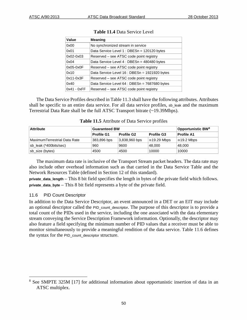
ATSC A/90:2013 ATSC Data Broadcast Standard 28 October 2013
50
Table 11.4 Data Service Level Value Meaning 0x00 No synchronized stream in service 0x01 Data Service Level 1 : DBESn = 120120 bytes 0x02-0x03 Reserved – see ATSC code point registry 0x04 Data Service Level 4 : DBESn = 480480 bytes 0x05-0x0F Reserved – see ATSC code point registry 0x10 Data Service Level 16 : DBESn = 1921920 bytes 0x11-0x3F Reserved – see ATSC code point registry 0x40 Data Service Level 64 : DBESn = 7687680 bytes 0x41 - 0xFF Reserved – see ATSC code point registry
The Data Service Profiles described in Table 11.3 shall have the following attributes. Attributes shall be specific to an entire data service. For all data service profiles, sb_leak and the maximum Terrestrial Data Rate shall be the full ATSC Transport bitrate (~19.39Mbps).
Table 11.5 Attribute of Data Service profiles Attribute Guaranteed BW Opportunistic BW8
Profile G1 Profile G2 Profile G3 Profile A1 MaximumTerrestrial Data Rate 383,896 bps 3,838,960 bps ≅19.29 Mbps ≅19.2 Mbps sb_leak (*400bits/sec) 960 9600 48,000 48,000 sb_size (bytes) 4500 4500 10000 10000
The maximum data rate is inclusive of the Transport Stream packet headers. The data rate may also include other overhead information such as that carried in the Data Service Table and the Network Resources Table (defined in Section 12 of this standard). private_data_length – This 8 bit field specifies the length in bytes of the private field which follows. private_data_byte – This 8 bit field represents a byte of the private field.
11.6 PID Count Descriptor In addition to the Data Service Descriptor, an event announced in a DET or an EIT may include an optional descriptor called the PID_count_descriptor. The purpose of this descriptor is to provide a total count of the PIDs used in the service, including the one associated with the data elementary stream conveying the Service Description Framework information. Optionally, the descriptor may also feature a field specifying the minimum number of PID values that a receiver must be able to monitor simultaneously to provide a meaningful rendition of the data service. Table 11.6 defines the syntax for the PID_count_descriptor structure.
8 See SMPTE 325M [17] for additional information about opportunistic insertion of data in an
ATSC multiplex.
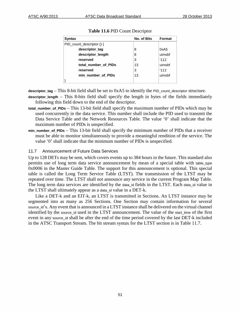
ATSC A/90:2013 ATSC Data Broadcast Standard 28 October 2013
51
Table 11.6 PID Count Descriptor Syntax No. of Bits Format PID_count_descriptor () { descriptor_tag 8 0xA5 descriptor_length 8 uimsbf reserved 3 ‘111’ total_number_of_PIDs 13 uimsbf reserved 3 ‘111’ min_number_of_PIDs 13 uimsbf }
descriptor_tag – This 8-bit field shall be set to 0xA5 to identify the PID_count_descriptor structure. descriptor_length – This 8-bits field shall specify the length in bytes of the fields immediately
following this field down to the end of the descriptor. total_number_of_PIDs – This 13-bit field shall specify the maximum number of PIDs which may be
used concurrently in the data service. This number shall include the PID used to transmit the Data Service Table and the Network Resources Table. The value ‘0’ shall indicate that the maximum number of PIDs is unspecified.
min_number_of_PIDs – This 13-bit field shall specify the minimum number of PIDs that a receiver must be able to monitor simultaneously to provide a meaningful rendition of the service. The value ‘0’ shall indicate that the minimum number of PIDs is unspecified.
11.7 Announcement of Future Data Services Up to 128 DETs may be sent, which covers events up to 384 hours in the future. This standard also permits use of long term data service announcement by mean of a special table with table_type 0x0006 in the Master Guide Table. The support for this announcement is optional. This special table is called the Long Term Service Table (LTST). The transmission of the LTST may be repeated over time. The LTST shall not announce any service in the current Program Map Table. The long term data services are identified by the data_id fields in the LTST. Each data_id value in the LTST shall ultimately appear as a data_id value in a DET-k.
Like a DET-k and an EIT-k, an LTST is transmitted in Sections. An LTST instance may be segmented into as many as 256 Sections. One Section may contain information for several source_id’s. Any event that is announced in a LTST instance shall be delivered on the virtual channel identified by the source_id used in the LTST announcement. The value of the start_time of the first event in any source_id shall be after the end of the time period covered by the last DET-k included in the ATSC Transport Stream. The bit stream syntax for the LTST section is in Table 11.7.
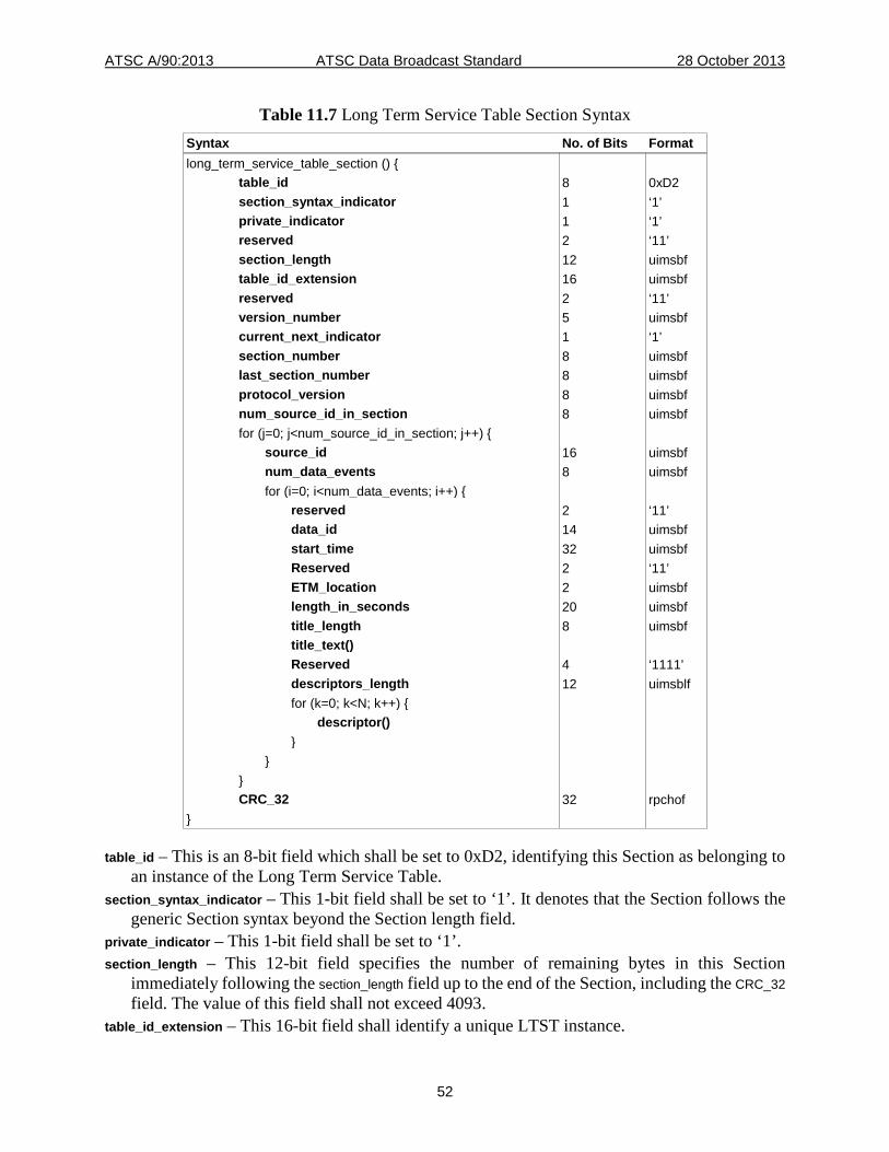
ATSC A/90:2013 ATSC Data Broadcast Standard 28 October 2013
52
Table 11.7 Long Term Service Table Section Syntax Syntax No. of Bits Format long_term_service_table_section () { table_id 8 0xD2 section_syntax_indicator 1 ‘1’ private_indicator 1 ‘1’ reserved 2 ‘11’ section_length 12 uimsbf table_id_extension 16 uimsbf reserved 2 ‘11’ version_number 5 uimsbf current_next_indicator 1 ‘1’ section_number 8 uimsbf last_section_number 8 uimsbf protocol_version 8 uimsbf num_source_id_in_section 8 uimsbf for (j=0; j<num_source_id_in_section; j++) { source_id 16 uimsbf num_data_events 8 uimsbf for (i=0; i<num_data_events; i++) { reserved 2 ‘11’ data_id 14 uimsbf start_time 32 uimsbf Reserved 2 ‘11’ ETM_location 2 uimsbf length_in_seconds 20 uimsbf title_length 8 uimsbf title_text() Reserved 4 ‘1111’ descriptors_length 12 uimsblf for (k=0; k<N; k++) { descriptor() } } } CRC_32 32 rpchof }
table_id – This is an 8-bit field which shall be set to 0xD2, identifying this Section as belonging to an instance of the Long Term Service Table.
section_syntax_indicator – This 1-bit field shall be set to ‘1’. It denotes that the Section follows the generic Section syntax beyond the Section length field.
private_indicator – This 1-bit field shall be set to ‘1’. section_length – This 12-bit field specifies the number of remaining bytes in this Section
immediately following the section_length field up to the end of the Section, including the CRC_32 field. The value of this field shall not exceed 4093.
table_id_extension – This 16-bit field shall identify a unique LTST instance.
ATSC A/90:2013 ATSC Data Broadcast Standard 28 October 2013
53
version_number – This 5-bit field is the version number of the LTST instance. The version number shall be incremented by 1 modulo 32 when any field in the LTST instance changes. Incrementing the value of this field shall force incrementing the value of the corresponding table_type_version_number in the MGT of A/65 [3] so that the version value remains identical.
current_next_indicator – This 1-bit indicator is always set to ‘1’ for LTST sections; the program guide sent is always currently applicable.
section_number – This 8-bit field gives the number of this Section. last_section_number – This 8-bit field specifies the number of the last Section. protocol_version – An 8-bit unsigned integer field whose function is to allow, in the future, any
defined table type to carry parameters that may be structured differently than those defined in the current protocol. At present, all defined message types in this protocol are defined for protocol_version zero only. Nonzero values of protocol_version may only be processed by decoders designed to accommodate later versions of the protocol as they become standardized.
num_source_id_in_section – This 8-bit field shall specify the number of source_id values listed in this LTST section.
source_id – This 16-bit field shall be used to link the announced events with the source_id of the virtual channel on which they will be carried. A source_id value of 0x0000 shall indicate that the virtual channel for the set of events in this source_id’s loop is unspecified. Source_id values in the range 0x0001 to 0x0FFF shall be unique within the Transport Stream that carries the LTST, while values 0x1000 to 0xFFFF shall be unique at the regional level. Values for source_id values 0x1000 and above shall be issued and administered by a Registration Authority designated by ATSC. As contrasted with A/65 [3], a virtual channel with this source_id is not required to be in the TVCT of A/65 [3] or the CVCT of A/65 [3] when the LTST is transmitted, though that is recommended.
num_data_events – This 8-bit field shall specify the number of data events for the value of the source_id field preceding this field.
data_id – This 14-bit field shall specify the identification number of the data event described. It shall be unique for each source_id value.
start_time – A 32-bit unsigned integer quantity representing the start time of this data event as the number of GPS seconds since 00:00:00 hours UTC, January 6th, 1980. This field also represents the download start time for scheduled events.
ETM_location – This 2-bit flag shall always be set to ‘00’. length_in_seconds – This 20-bit field shall specify the duration (in seconds) of this data event. For
unbounded events, this value shall be 0xFFFF. In the case of an unbounded event, the upper bound for the event duration is determined by the start_time of the next event on the same virtual channel.
title_length – This 8-bit field shall specify the length in bytes for title_text (0 through 255). The value 0x00 shall indicate that no title exists for this data event.
title_text() – The event title in the format of Multiple Compressed Strings. See Reference A/65 [3] Section 6.8.
descriptors_length – This 12-bit field shall specify the total length in bytes of the data event descriptors that follow.
CRC_32 – This is a 32-bit field that contains the CRC value that ensures a zero output from the registers in the decoder defined in Annex B of ISO/IEC 13818-1 [8] after processing the entire LTST section.
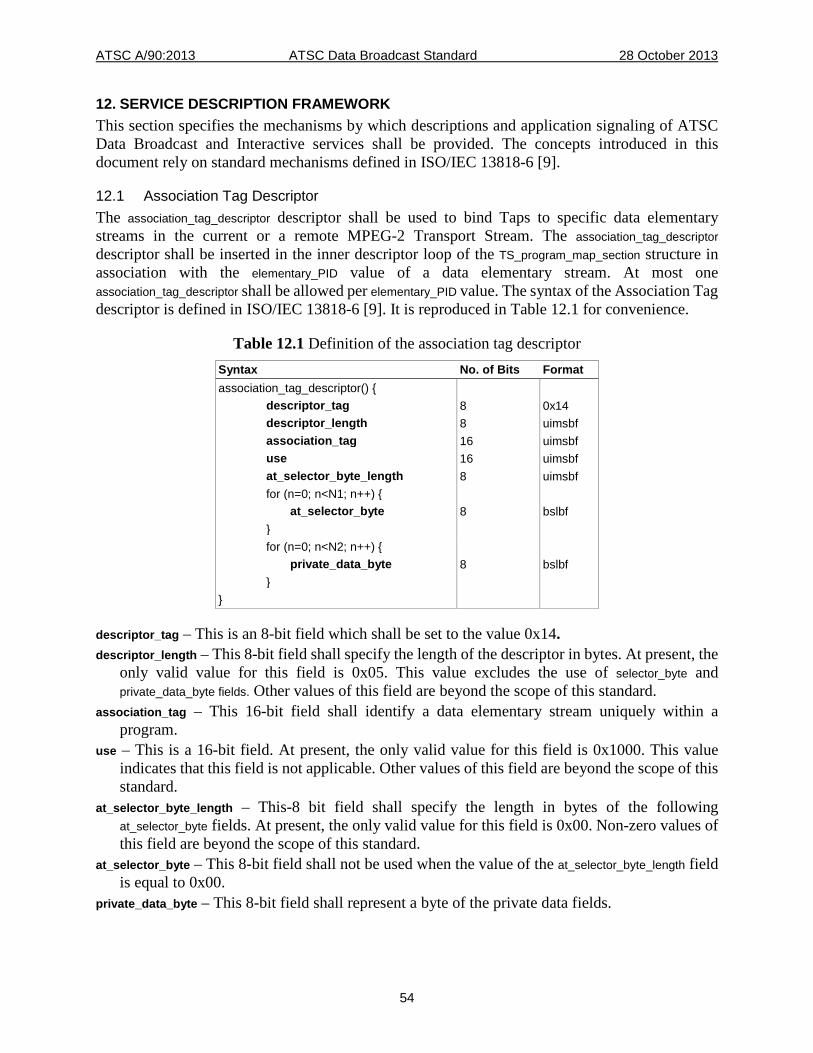
ATSC A/90:2013 ATSC Data Broadcast Standard 28 October 2013
54
12. SERVICE DESCRIPTION FRAMEWORK This section specifies the mechanisms by which descriptions and application signaling of ATSC Data Broadcast and Interactive services shall be provided. The concepts introduced in this document rely on standard mechanisms defined in ISO/IEC 13818-6 [9].
12.1 Association Tag Descriptor The association_tag_descriptor descriptor shall be used to bind Taps to specific data elementary streams in the current or a remote MPEG-2 Transport Stream. The association_tag_descriptor descriptor shall be inserted in the inner descriptor loop of the TS_program_map_section structure in association with the elementary_PID value of a data elementary stream. At most one association_tag_descriptor shall be allowed per elementary_PID value. The syntax of the Association Tag descriptor is defined in ISO/IEC 13818-6 [9]. It is reproduced in Table 12.1 for convenience.
Table 12.1 Definition of the association tag descriptor Syntax No. of Bits Format association_tag_descriptor() { descriptor_tag 8 0x14 descriptor_length 8 uimsbf association_tag 16 uimsbf use 16 uimsbf at_selector_byte_length 8 uimsbf for (n=0; n<N1; n++) { at_selector_byte 8 bslbf } for (n=0; n<N2; n++) { private_data_byte 8 bslbf } }
descriptor_tag – This is an 8-bit field which shall be set to the value 0x14. descriptor_length – This 8-bit field shall specify the length of the descriptor in bytes. At present, the
only valid value for this field is 0x05. This value excludes the use of selector_byte and private_data_byte fields. Other values of this field are beyond the scope of this standard.
association_tag – This 16-bit field shall identify a data elementary stream uniquely within a program.
use – This is a 16-bit field. At present, the only valid value for this field is 0x1000. This value indicates that this field is not applicable. Other values of this field are beyond the scope of this standard.
at_selector_byte_length – This-8 bit field shall specify the length in bytes of the following at_selector_byte fields. At present, the only valid value for this field is 0x00. Non-zero values of this field are beyond the scope of this standard.
at_selector_byte – This 8-bit field shall not be used when the value of the at_selector_byte_length field is equal to 0x00.
private_data_byte – This 8-bit field shall represent a byte of the private data fields.
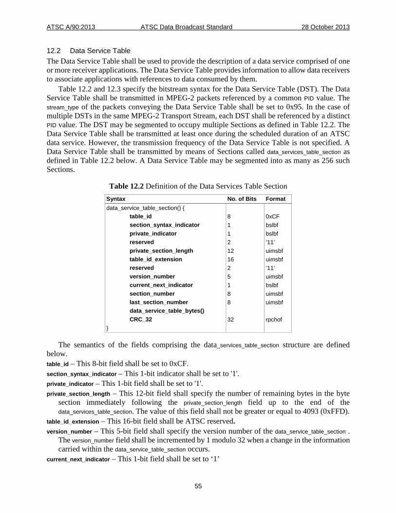
ATSC A/90:2013 ATSC Data Broadcast Standard 28 October 2013
55
12.2 Data Service Table The Data Service Table shall be used to provide the description of a data service comprised of one or more receiver applications. The Data Service Table provides information to allow data receivers to associate applications with references to data consumed by them.
Table 12.2 and 12.3 specify the bitstream syntax for the Data Service Table (DST). The Data Service Table shall be transmitted in MPEG-2 packets referenced by a common PID value. The stream_type of the packets conveying the Data Service Table shall be set to 0x95. In the case of multiple DSTs in the same MPEG-2 Transport Stream, each DST shall be referenced by a distinct PID value. The DST may be segmented to occupy multiple Sections as defined in Table 12.2. The Data Service Table shall be transmitted at least once during the scheduled duration of an ATSC data service. However, the transmission frequency of the Data Service Table is not specified. A Data Service Table shall be transmitted by means of Sections called data_services_table_section as defined in Table 12.2 below. A Data Service Table may be segmented into as many as 256 such Sections.
Table 12.2 Definition of the Data Services Table Section Syntax No. of Bits Format data_service_table_section() { table_id 8 0xCF section_syntax_indicator 1 bslbf private_indicator 1 bslbf reserved 2 ‘11’ private_section_length 12 uimsbf table_id_extension 16 uimsbf reserved 2 ‘11’ version_number 5 uimsbf current_next_indicator 1 bslbf section_number 8 uimsbf last_section_number 8 uimsbf data_service_table_bytes() CRC_32 32 rpchof }
The semantics of the fields comprising the data_services_table_section structure are defined below. table_id – This 8-bit field shall be set to 0xCF. section_syntax_indicator – This 1-bit indicator shall be set to '1'. private_indicator – This 1-bit field shall be set to '1'. private_section_length – This 12-bit field shall specify the number of remaining bytes in the byte
section immediately following the private_section_length field up to the end of the data_services_table_section. The value of this field shall not be greater or equal to 4093 (0xFFD).
table_id_extension – This 16-bit field shall be ATSC reserved. version_number – This 5-bit field shall specify the version number of the data_service_table_section .
The version_number field shall be incremented by 1 modulo 32 when a change in the information carried within the data_service_table_section occurs.
current_next_indicator – This 1-bit field shall be set to ‘1’
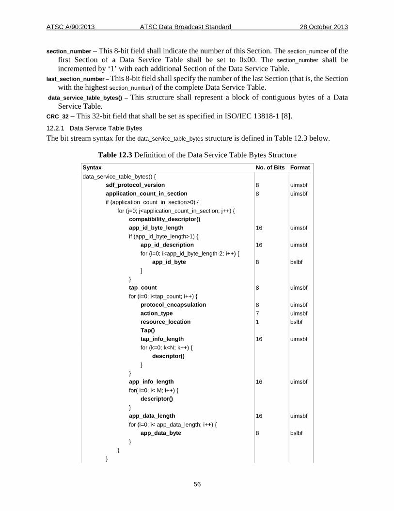
ATSC A/90:2013 ATSC Data Broadcast Standard 28 October 2013
56
section_number – This 8-bit field shall indicate the number of this Section. The section_number of the first Section of a Data Service Table shall be set to 0x00. The section_number shall be incremented by ‘1’ with each additional Section of the Data Service Table.
last_section_number – This 8-bit field shall specify the number of the last Section (that is, the Section with the highest section_number) of the complete Data Service Table.
data_service_table_bytes() – This structure shall represent a block of contiguous bytes of a Data Service Table.
CRC_32 – This 32-bit field that shall be set as specified in ISO/IEC 13818-1 [8]. 12.2.1 Data Service Table Bytes The bit stream syntax for the data_service_table_bytes structure is defined in Table 12.3 below.
Table 12.3 Definition of the Data Service Table Bytes Structure Syntax No. of Bits Format data_service_table_bytes() { sdf_protocol_version 8 uimsbf application_count_in_section 8 uimsbf if (application_count_in_section>0) { for (j=0; j<application_count_in_section; j++) { compatibility_descriptor() app_id_byte_length 16 uimsbf if (app_id_byte_length>1) { app_id_description 16 uimsbf for (i=0; i<app_id_byte_length-2; i++) { app_id_byte 8 bslbf } } tap_count 8 uimsbf for (i=0; i<tap_count; i++) { protocol_encapsulation 8 uimsbf action_type 7 uimsbf resource_location 1 bslbf Tap() tap_info_length 16 uimsbf for (k=0; k<N; k++) { descriptor() } } app_info_length 16 uimsbf for( i=0; i< M; i++) { descriptor() } app_data_length 16 uimsbf for (i=0; i< app_data_length; i++) { app_data_byte 8 bslbf } } }
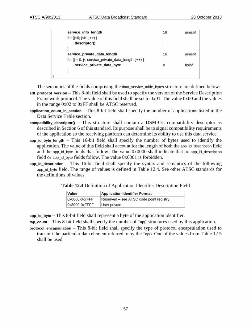
ATSC A/90:2013 ATSC Data Broadcast Standard 28 October 2013
57
service_info_length 16 uimsbf for (j=0; j<K; j++) { descriptor() } service_private_data_length 16 uimsbf for (j = 0; j< service_private_data_length; j++) { service_private_data_byte 8 bslbf } }
The semantics of the fields comprising the data_service_table_bytes structure are defined below. sdf_protocol_version – This 8-bit field shall be used to specify the version of the Service Description
Framework protocol. The value of this field shall be set to 0x01. The value 0x00 and the values in the range 0x02 to 0xFF shall be ATSC reserved.
application_count_in_section – This 8-bit field shall specify the number of applications listed in the Data Service Table section.
compatibility_descriptor() – This structure shall contain a DSM-CC compatibility descriptor as described in Section 6 of this standard. Its purpose shall be to signal compatibility requirements of the application so the receiving platform can determine its ability to use this data service.
app_id_byte_length – This 16-bit field shall specify the number of bytes used to identify the application. The value of this field shall account for the length of both the app_id_description field and the app_id_byte fields that follow. The value 0x0000 shall indicate that no app_id_description field or app_id_byte fields follow. The value 0x0001 is forbidden.
app_id_description – This 16-bit field shall specify the syntax and semantics of the following app_id_byte field. The range of values is defined in Table 12.4. See other ATSC standards for the definitions of values.
Table 12.4 Definition of Application Identifier Description Field Value Application Identifier Format 0x0000-0x7FFF Reserved – see ATSC code point registry 0x8000-0xFFFF User private
app_id_byte – This 8-bit field shall represent a byte of the application identifier. tap_count – This 8-bit field shall specify the number of Tap() structures used by this application. protocol_encapsulation – This 8-bit field shall specify the type of protocol encapsulation used to
transmit the particular data element referred to by the Tap(). One of the values from Table 12.5 shall be used.
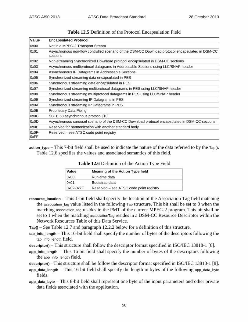
ATSC A/90:2013 ATSC Data Broadcast Standard 28 October 2013
58
Table 12.5 Definition of the Protocol Encapsulation Field Value Encapsulated Protocol 0x00 Not in a MPEG-2 Transport Stream 0x01 Asynchronous non-flow controlled scenario of the DSM-CC Download protocol encapsulated in DSM-CC
sections 0x02 Non-streaming Synchronized Download protocol encapsulated in DSM-CC sections 0x03 Asynchronous multiprotocol datagrams in Addressable Sections using LLC/SNAP header 0x04 Asynchronous IP Datagrams in Addressable Sections 0x05 Synchronized streaming data encapsulated in PES 0x06 Synchronous streaming data encapsulated in PES 0x07 Synchronized streaming multiprotocol datagrams in PES using LLC/SNAP header 0x08 Synchronous streaming multiprotocol datagrams in PES using LLC/SNAP header 0x09 Synchronized streaming IP Datagrams in PES 0x0A Synchronous streaming IP Datagrams in PES 0x0B Proprietary Data Piping 0x0C SCTE 53 asynchronous protocol [10] 0x0D Asynchronous carousel scenario of the DSM-CC Download protocol encapsulated in DSM-CC sections 0x0E Reserved for harmonization with another standard body 0x0F-0xFF
Reserved – see ATSC code point registry
action_type – This 7-bit field shall be used to indicate the nature of the data referred to by the Tap(). Table 12.6 specifies the values and associated semantics of this field.
Table 12.6 Definition of the Action Type Field Value Meaning of the Action Type field 0x00 Run-time data 0x01 Bootstrap data 0x02-0x7F Reserved – see ATSC code point registry
resource_location – This 1-bit field shall specify the location of the Association Tag field matching the association_tag value listed in the following Tap structure. This bit shall be set to 0 when the matching association_tag resides in the PMT of the current MPEG-2 program. This bit shall be set to 1 when the matching associationTag resides in a DSM-CC Resource Descriptor within the Network Resources Table of this Data Service.
Tap() – See Table 12.7 and paragraph 12.2.2 below for a definition of this structure. tap_info_length – This 16-bit field shall specify the number of bytes of the descriptors following the
tap_info_length field. descriptor() – This structure shall follow the descriptor format specified in ISO/IEC 13818-1 [8]. app_info_length – This 16-bit field shall specify the number of bytes of the descriptors following
the app_info_length field. descriptor() – This structure shall be follow the descriptor format specified in ISO/IEC 13818-1 [8]. app_data_length – This 16-bit field shall specify the length in bytes of the following app_data_byte
fields. app_data_byte – This 8-bit field shall represent one byte of the input parameters and other private
data fields associated with the application.
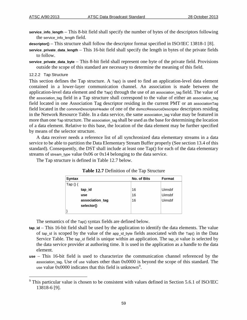
ATSC A/90:2013 ATSC Data Broadcast Standard 28 October 2013
59
service_info_length – This 8-bit field shall specify the number of bytes of the descriptors following the service_info_length field.
descriptor() – This structure shall follow the descriptor format specified in ISO/IEC 13818-1 [8]. service_private_data_length – This 16-bit field shall specify the length in bytes of the private fields
to follow. service_private_data_byte – This 8-bit field shall represent one byte of the private field. Provisions
outside the scope of this standard are necessary to determine the meaning of this field. 12.2.2 Tap Structure This section defines the Tap structure. A Tap() is used to find an application-level data element contained in a lower-layer communication channel. An association is made between the application-level data element and the Tap() through the use of an association_tag field. The value of the association_tag field in a Tap structure shall correspond to the value of either an association_tag field located in one Association Tag descriptor residing in the current PMT or an associationTag field located in the commonDescriptorHeader of one of the dsmccResourceDescriptor descriptors residing in the Network Resource Table. In a data service, the same association_tag value may be featured in more than one Tap structure. The association_tag shall be used as the base for determining the location of a data element. Relative to this base, the location of the data element may be further specified by means of the selector structure.
A data receiver needs a reference list of all synchronized data elementary streams in a data service to be able to partition the Data Elementary Stream Buffer properly (See section 13.4 of this standard). Consequently, the DST shall include at least one Tap() for each of the data elementary streams of stream_type value 0x06 or 0x14 belonging to the data service.
The Tap structure is defined in Table 12.7 below.
Table 12.7 Definition of the Tap Structure Syntax No. of Bits Format Tap () { tap_id 16 Uimsbf use 16 Uimsbf association_tag 16 Uimsbf selector() }
The semantics of the Tap() syntax fields are defined below. tap_id – This 16-bit field shall be used by the application to identify the data elements. The value
of tap_id is scoped by the value of the app_id_byte fields associated with the Tap() in the Data Service Table. The tap_id field is unique within an application. The tap_id value is selected by the data service provider at authoring time. It is used in the application as a handle to the data element.
use – This 16-bit field is used to characterize the communication channel referenced by the association_tag. Use of use values other than 0x0000 is beyond the scope of this standard. The use value 0x0000 indicates that this field is unknown9.
9 This particular value is chosen to be consistent with values defined in Section 5.6.1 of ISO/IEC
13818-6 [9].
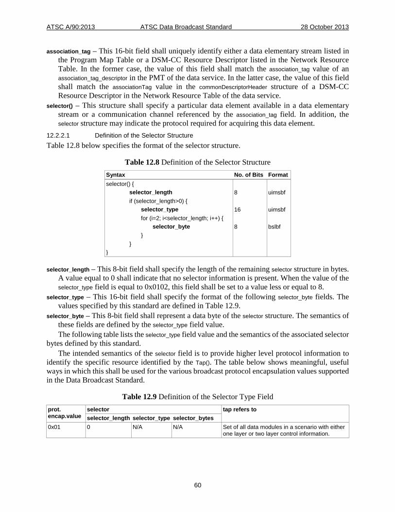
ATSC A/90:2013 ATSC Data Broadcast Standard 28 October 2013
60
association_tag – This 16-bit field shall uniquely identify either a data elementary stream listed in the Program Map Table or a DSM-CC Resource Descriptor listed in the Network Resource Table. In the former case, the value of this field shall match the association_tag value of an association_tag_descriptor in the PMT of the data service. In the latter case, the value of this field shall match the associationTag value in the commonDescriptorHeader structure of a DSM-CC Resource Descriptor in the Network Resource Table of the data service.
selector() – This structure shall specify a particular data element available in a data elementary stream or a communication channel referenced by the association_tag field. In addition, the selector structure may indicate the protocol required for acquiring this data element.
12.2.2.1 Definition of the Selector Structure Table 12.8 below specifies the format of the selector structure.
Table 12.8 Definition of the Selector Structure Syntax No. of Bits Format selector() { selector_length 8 uimsbf if (selector_length>0) { selector_type 16 uimsbf for (i=2; i<selector_length; i++) { selector_byte 8 bslbf } } }
selector_length – This 8-bit field shall specify the length of the remaining selector structure in bytes. A value equal to 0 shall indicate that no selector information is present. When the value of the selector_type field is equal to 0x0102, this field shall be set to a value less or equal to 8.
selector_type – This 16-bit field shall specify the format of the following selector_byte fields. The values specified by this standard are defined in Table 12.9.
selector_byte – This 8-bit field shall represent a data byte of the selector structure. The semantics of these fields are defined by the selector_type field value. The following table lists the selector_type field value and the semantics of the associated selector
bytes defined by this standard. The intended semantics of the selector field is to provide higher level protocol information to
identify the specific resource identified by the Tap(). The table below shows meaningful, useful ways in which this shall be used for the various broadcast protocol encapsulation values supported in the Data Broadcast Standard.
Table 12.9 Definition of the Selector Type Field prot. encap.value
selector tap refers to selector_length selector_type selector_bytes
0x01 0 N/A N/A Set of all data modules in a scenario with either one layer or two layer control information.
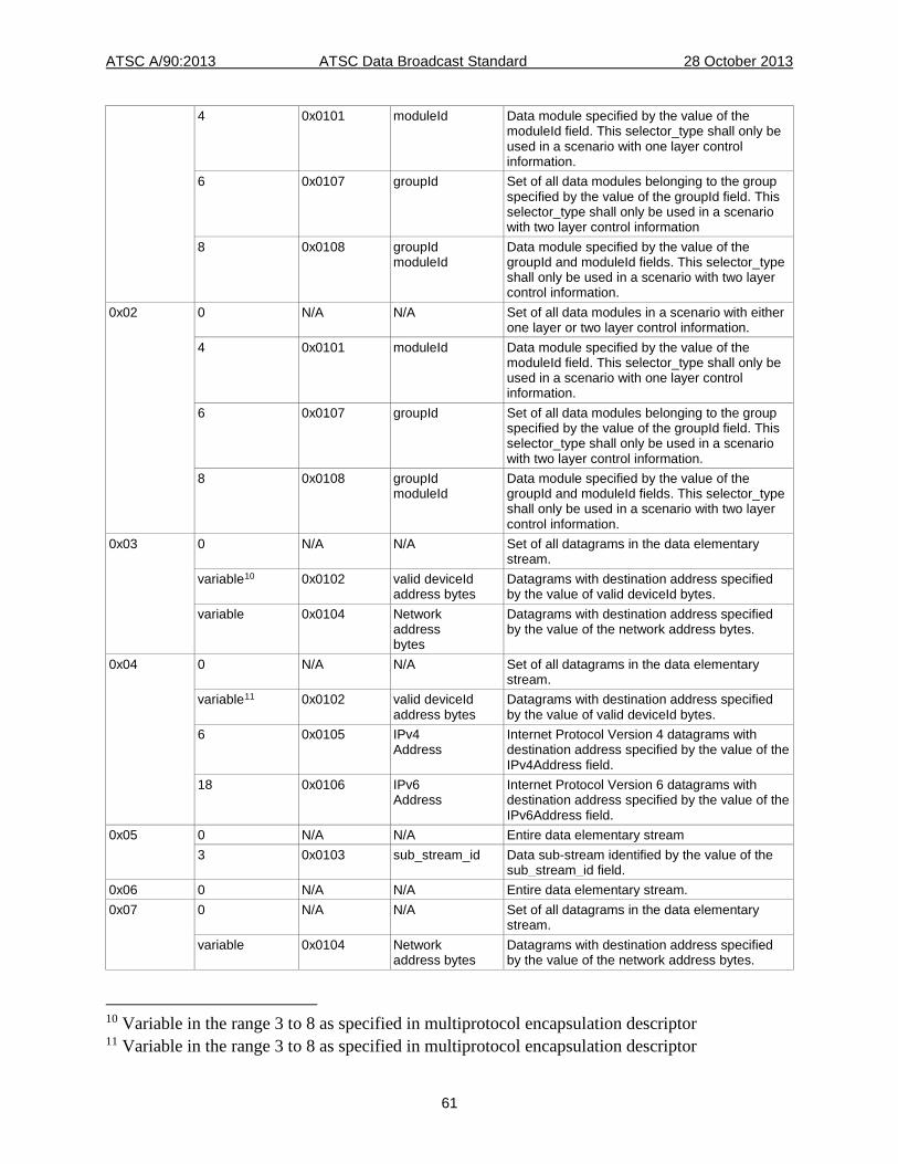
ATSC A/90:2013 ATSC Data Broadcast Standard 28 October 2013
61
4 0x0101 moduleId Data module specified by the value of the moduleId field. This selector_type shall only be used in a scenario with one layer control information.
6 0x0107 groupId Set of all data modules belonging to the group specified by the value of the groupId field. This selector_type shall only be used in a scenario with two layer control information
8 0x0108 groupId moduleId
Data module specified by the value of the groupId and moduleId fields. This selector_type shall only be used in a scenario with two layer control information.
0x02 0 N/A N/A Set of all data modules in a scenario with either one layer or two layer control information.
4 0x0101 moduleId Data module specified by the value of the moduleId field. This selector_type shall only be used in a scenario with one layer control information.
6 0x0107 groupId Set of all data modules belonging to the group specified by the value of the groupId field. This selector_type shall only be used in a scenario with two layer control information.
8 0x0108 groupId moduleId
Data module specified by the value of the groupId and moduleId fields. This selector_type shall only be used in a scenario with two layer control information.
0x03 0 N/A N/A Set of all datagrams in the data elementary stream.
variable10 0x0102 valid deviceId address bytes
Datagrams with destination address specified by the value of valid deviceId bytes.
variable 0x0104 Network address bytes
Datagrams with destination address specified by the value of the network address bytes.
0x04 0 N/A N/A Set of all datagrams in the data elementary stream.
variable11 0x0102 valid deviceId address bytes
Datagrams with destination address specified by the value of valid deviceId bytes.
6 0x0105 IPv4 Address
Internet Protocol Version 4 datagrams with destination address specified by the value of the IPv4Address field.
18 0x0106 IPv6 Address
Internet Protocol Version 6 datagrams with destination address specified by the value of the IPv6Address field.
0x05 0 N/A N/A Entire data elementary stream 3 0x0103 sub_stream_id Data sub-stream identified by the value of the
sub_stream_id field. 0x06 0 N/A N/A Entire data elementary stream. 0x07 0 N/A N/A Set of all datagrams in the data elementary
stream. variable 0x0104 Network
address bytes Datagrams with destination address specified by the value of the network address bytes.
10 Variable in the range 3 to 8 as specified in multiprotocol encapsulation descriptor 11 Variable in the range 3 to 8 as specified in multiprotocol encapsulation descriptor
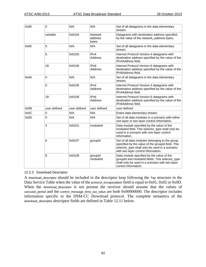
ATSC A/90:2013 ATSC Data Broadcast Standard 28 October 2013
62
0x08 0 N/A N/A Set of all datagrams in the data elementary stream.
variable 0x0104 Network address bytes
Datagrams with destination address specified by the value of the network_address bytes.
0x09 0 N/A N/A Set of all datagrams in the data elementary stream.
6 0x0105 IPv4 Address
Internet Protocol Version 4 datagrams with destination address specified by the value of the IPv4Address field.
18 0x0106 IPv6 Address
Internet Protocol Version 6 datagrams with destination address specified by the value of the IPv6Address field.
0x0A 0 N/A N/A Set of all datagrams in the data elementary stream.
6 0x0105 IPv4 Address
Internet Protocol Version 4 datagrams with destination address specified by the value of the IPv4Address field.
18 0x0106 IPv6 Address
Internet Protocol Version 6 datagrams with destination address specified by the value of the IPv6Address field.
0x0B user defined user defined user defined user defined 0x0C 0 N/A N/A Entire data elementary stream. 0x0D 0 N/A N/A Set of all data modules in a scenario with either
one layer or two layer control information. 4 0x0101 moduleId Data module specified by the value of the
moduleId field. This selector_type shall only be used in a scenario with one layer control information.
6 0x0107 groupId Set of all data modules belonging to the group specified by the value of the groupId field. This selector_type shall only be used in a scenario with two layer control information.
8 0x0108 groupId moduleId
Data module specified by the value of the groupId and moduleId fields. This selector_type shall only be used in a scenario with two layer control information.
12.2.3 Download Descriptor A download_descriptor should be included in the descriptor loop following the Tap structure in the Data Service Table when the value of the protocol_encapsulation field is equal to 0x01, 0x02 or 0x0D. When the download_descriptor is not present the receiver should assume that the values of carousel_period and the control_message_time_out_value are both 0x00000000. The descriptor includes information specific to the DSM-CC Download protocol. The complete semantics of the download_descriptor descriptor fields are defined in Table 12.11 below.
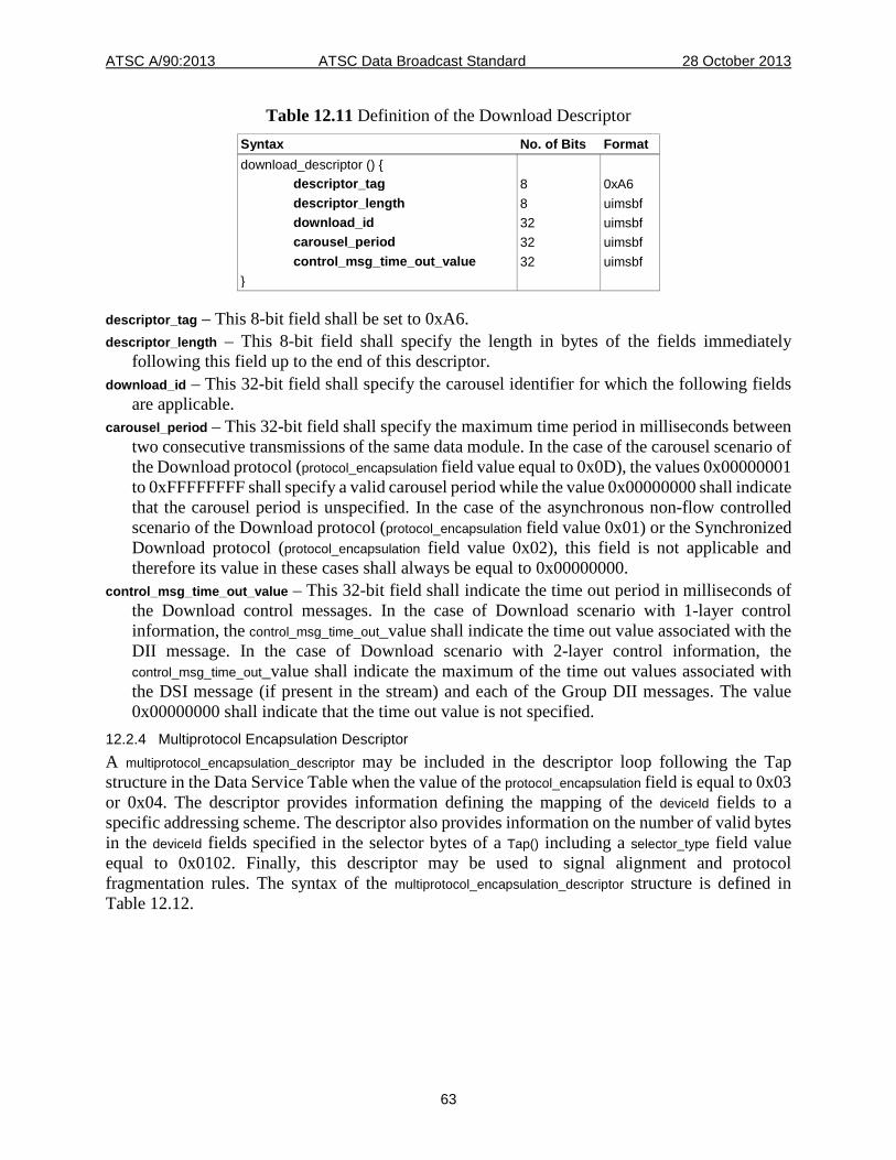
ATSC A/90:2013 ATSC Data Broadcast Standard 28 October 2013
63
Table 12.11 Definition of the Download Descriptor Syntax No. of Bits Format download_descriptor () { descriptor_tag 8 0xA6 descriptor_length 8 uimsbf download_id 32 uimsbf carousel_period 32 uimsbf control_msg_time_out_value 32 uimsbf }
descriptor_tag – This 8-bit field shall be set to 0xA6. descriptor_length – This 8-bit field shall specify the length in bytes of the fields immediately
following this field up to the end of this descriptor. download_id – This 32-bit field shall specify the carousel identifier for which the following fields
are applicable. carousel_period – This 32-bit field shall specify the maximum time period in milliseconds between
two consecutive transmissions of the same data module. In the case of the carousel scenario of the Download protocol (protocol_encapsulation field value equal to 0x0D), the values 0x00000001 to 0xFFFFFFFF shall specify a valid carousel period while the value 0x00000000 shall indicate that the carousel period is unspecified. In the case of the asynchronous non-flow controlled scenario of the Download protocol (protocol_encapsulation field value 0x01) or the Synchronized Download protocol (protocol_encapsulation field value 0x02), this field is not applicable and therefore its value in these cases shall always be equal to 0x00000000.
control_msg_time_out_value – This 32-bit field shall indicate the time out period in milliseconds of the Download control messages. In the case of Download scenario with 1-layer control information, the control_msg_time_out_value shall indicate the time out value associated with the DII message. In the case of Download scenario with 2-layer control information, the control_msg_time_out_value shall indicate the maximum of the time out values associated with the DSI message (if present in the stream) and each of the Group DII messages. The value 0x00000000 shall indicate that the time out value is not specified.
12.2.4 Multiprotocol Encapsulation Descriptor A multiprotocol_encapsulation_descriptor may be included in the descriptor loop following the Tap structure in the Data Service Table when the value of the protocol_encapsulation field is equal to 0x03 or 0x04. The descriptor provides information defining the mapping of the deviceId fields to a specific addressing scheme. The descriptor also provides information on the number of valid bytes in the deviceId fields specified in the selector bytes of a Tap() including a selector_type field value equal to 0x0102. Finally, this descriptor may be used to signal alignment and protocol fragmentation rules. The syntax of the multiprotocol_encapsulation_descriptor structure is defined in Table 12.12.
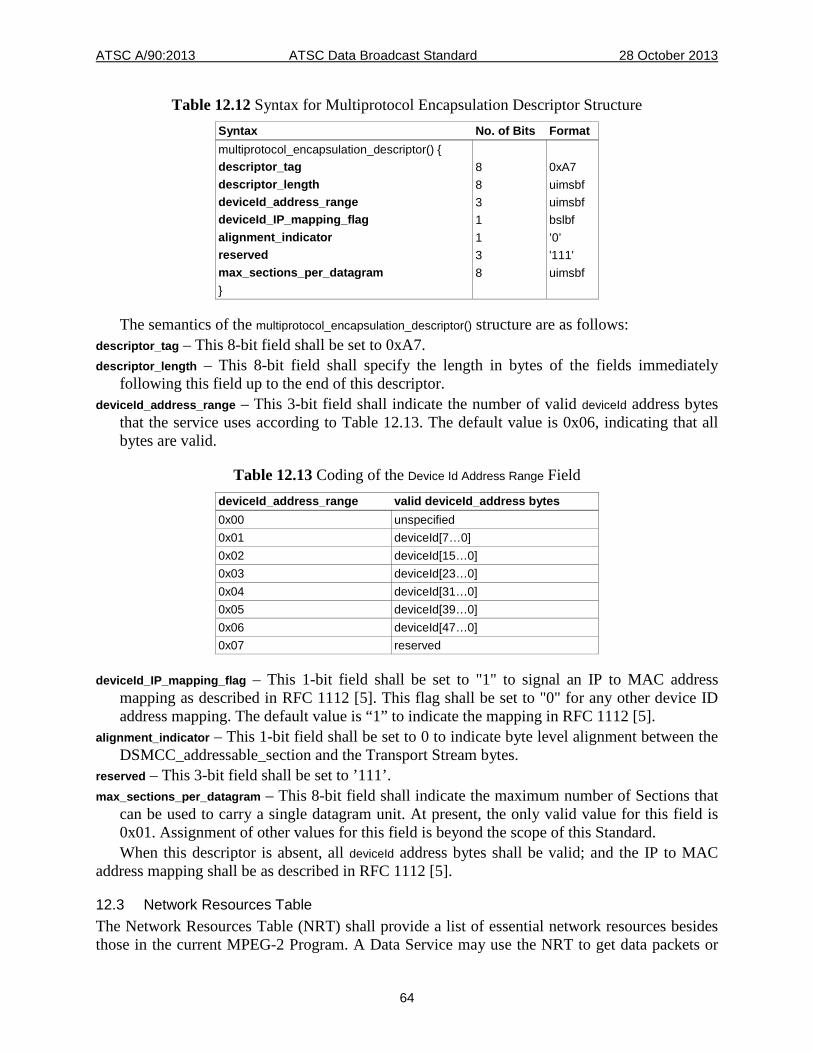
ATSC A/90:2013 ATSC Data Broadcast Standard 28 October 2013
64
Table 12.12 Syntax for Multiprotocol Encapsulation Descriptor Structure Syntax No. of Bits Format multiprotocol_encapsulation_descriptor() { descriptor_tag 8 0xA7 descriptor_length 8 uimsbf deviceId_address_range 3 uimsbf deviceId_IP_mapping_flag 1 bslbf alignment_indicator 1 ’0’ reserved 3 '111' max_sections_per_datagram 8 uimsbf }
The semantics of the multiprotocol_encapsulation_descriptor() structure are as follows: descriptor_tag – This 8-bit field shall be set to 0xA7. descriptor_length – This 8-bit field shall specify the length in bytes of the fields immediately
following this field up to the end of this descriptor. deviceId_address_range – This 3-bit field shall indicate the number of valid deviceId address bytes
that the service uses according to Table 12.13. The default value is 0x06, indicating that all bytes are valid.
Table 12.13 Coding of the Device Id Address Range Field deviceId_address_range valid deviceId_address bytes 0x00 unspecified 0x01 deviceId[7…0] 0x02 deviceId[15…0] 0x03 deviceId[23…0] 0x04 deviceId[31…0] 0x05 deviceId[39…0] 0x06 deviceId[47…0] 0x07 reserved
deviceId_IP_mapping_flag – This 1-bit field shall be set to "1" to signal an IP to MAC address mapping as described in RFC 1112 [5]. This flag shall be set to "0" for any other device ID address mapping. The default value is “1” to indicate the mapping in RFC 1112 [5].
alignment_indicator – This 1-bit field shall be set to 0 to indicate byte level alignment between the DSMCC_addressable_section and the Transport Stream bytes.
reserved – This 3-bit field shall be set to ’111’. max_sections_per_datagram – This 8-bit field shall indicate the maximum number of Sections that
can be used to carry a single datagram unit. At present, the only valid value for this field is 0x01. Assignment of other values for this field is beyond the scope of this Standard. When this descriptor is absent, all deviceId address bytes shall be valid; and the IP to MAC
address mapping shall be as described in RFC 1112 [5].
12.3 Network Resources Table The Network Resources Table (NRT) shall provide a list of essential network resources besides those in the current MPEG-2 Program. A Data Service may use the NRT to get data packets or

ATSC A/90:2013 ATSC Data Broadcast Standard 28 October 2013
65
datagrams other than the ones published in the Service Location Descriptor of the Virtual Channel. It may include data elementary streams in another MPEG-2 program within the same Transport Stream, data elementary streams in remote MPEG-2 Transport Streams, as well as bi-directional communication channels using other protocols such as IP. The Network Resources Table shall be transmitted in MPEG-2 packets referenced by a common PID value. In the case of multiple NRTs in the same MPEG-2 Transport Stream, each NRT shall be carried in packets identified with a distinct PID value. The PID value shall be identical to the value used for the MPEG-2 Transport packets conveying the Data Service Table associated with an NRT. The stream_type of the packets conveying the Network Resources Table shall be set to 0x95. The NRT may be segmented to occupy multiple Sections as defined in Table 12.13. The transmission of the Network Resources Table is optional for any ATSC data service using communication channels other than the current MPEG-2 Transport Stream. This standard does not establish the transmission frequency of the Network Resources Table. A Network Resources Table shall be transmitted by means of Sections called network_resources_table_section as defined in Table 12.14 below. A Network Resources Table may be segmented into as many as 256 such Sections.
Table 12.14 Network Resources Table Section Syntax No. of Bits Format network_resources_table_section() { table_id 8 0xD1 section_syntax_indicator 1 bslbf private_indicator 1 bslbf reserved 2 ‘11’ private_section_length 12 uimsbf table_id_extension 16 uimsbf reserved 2 ‘11’ version_number 5 uimsbf current_next_indicator 1 bslbf section_number 8 uimsbf last_section_number 8 uimsbf network_resources_table_bytes() CRC_32 32 rpchof }
table_id – This 8-bit field shall be set to 0xD1. section_syntax_indicator – This 1-bit field shall be set to '1'. private_indicator – This 1-bit field shall be set to '1'. private_section_length – This 12-bit field shall specify the number of remaining bytes in the byte
Section immediately following the private_section_length field up to the end of the network_resources_table_section. The value of this field shall not be equal or greater than 4093 (0xFFD).
table_id_extension – This 16-bit field shall be ATSC reserved. version_number – This 5-bit field shall specify the version number of the
network_resources_table_section. The version_number field shall be incremented by 1 modulo 32 when a change in the information carried within the network_resources_table_section occurs.
current_next_indicator – This 1-bit field which shall be set to ‘1’.
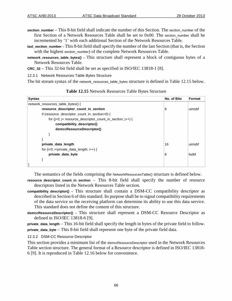
ATSC A/90:2013 ATSC Data Broadcast Standard 28 October 2013
66
section_number – This 8-bit field shall indicate the number of this Section. The section_number of the first Section of a Network Resources Table shall be set to 0x00. The section_number shall be incremented by ‘1’ with each additional Section of the Network Resources Table.
last_section_number – This 8-bit field shall specify the number of the last Section (that is, the Section with the highest section_number) of the complete Network Resources Table.
network_resources_table_bytes() – This structure shall represent a block of contiguous bytes of a Network Resources Table.
CRC_32 – This 32-bit field shall be set as specified in ISO/IEC 13818-1 [8]. 12.3.1 Network Resources Table Bytes Structure The bit stream syntax of the network_resources_table_bytes structure is defined in Table 12.15 below.
Table 12.15 Network Resources Table Bytes Structure Syntax No. of Bits Format network_resources_table_bytes() { resource_descriptor_count_in_section 8 uimsbf if (resource_descriptor_count_in_section>0) { for (j=0; j< resource_descriptor_count_in_section; j++) { compatibility_descriptor() dsmccResourceDescriptor() } } private_data_length 16 uimsbf for (i=0; i<private_data_length; i++) { private_data_byte 8 bslbf } }
The semantics of the fields comprising the NetworkResourcesTable() structure is defined below. resource_descriptor_count_in_section – This 8-bit field shall specify the number of resource
descriptors listed in the Network Resources Table section. compatibility_descriptor() – This structure shall contain a DSM-CC compatibility descriptor as
described in Section 6 of this standard. Its purpose shall be to signal compatibility requirements of the data service so the receiving platform can determine its ability to use this data service. This standard does not define the content of this structure.
dsmccResourceDescriptor() – This structure shall represent a DSM-CC Resource Descriptor as defined in ISO/IEC 13818-6 [9].
private_data_length – This 16-bit field shall specify the length in bytes of the private field to follow. private_data_byte – This 8-bit field shall represent one byte of the private field data. 12.3.2 DSM-CC Resource Descriptor This section provides a minimum list of the dsmccResourceDescriptor used in the Network Resources Table section structure. The general format of a Resource descriptor is defined in ISO/IEC 13818-6 [9]. It is reproduced in Table 12.16 below for convenience.
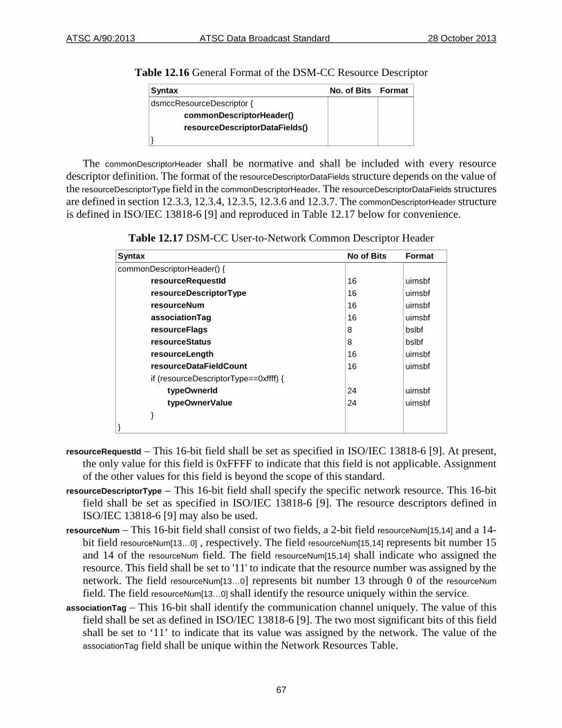
ATSC A/90:2013 ATSC Data Broadcast Standard 28 October 2013
67
Table 12.16 General Format of the DSM-CC Resource Descriptor Syntax No. of Bits Format dsmccResourceDescriptor { commonDescriptorHeader() resourceDescriptorDataFields() }
The commonDescriptorHeader shall be normative and shall be included with every resource descriptor definition. The format of the resourceDescriptorDataFields structure depends on the value of the resourceDescriptorType field in the commonDescriptorHeader. The resourceDescriptorDataFields structures are defined in section 12.3.3, 12.3.4, 12.3.5, 12.3.6 and 12.3.7. The commonDescriptorHeader structure is defined in ISO/IEC 13818-6 [9] and reproduced in Table 12.17 below for convenience.
Table 12.17 DSM-CC User-to-Network Common Descriptor Header Syntax No of Bits Format commonDescriptorHeader() { resourceRequestId 16 uimsbf resourceDescriptorType 16 uimsbf resourceNum 16 uimsbf associationTag 16 uimsbf resourceFlags 8 bslbf resourceStatus 8 bslbf resourceLength 16 uimsbf resourceDataFieldCount 16 uimsbf if (resourceDescriptorType==0xffff) { typeOwnerId 24 uimsbf typeOwnerValue 24 uimsbf } }
resourceRequestId – This 16-bit field shall be set as specified in ISO/IEC 13818-6 [9]. At present, the only value for this field is 0xFFFF to indicate that this field is not applicable. Assignment of the other values for this field is beyond the scope of this standard.
resourceDescriptorType – This 16-bit field shall specify the specific network resource. This 16-bit field shall be set as specified in ISO/IEC 13818-6 [9]. The resource descriptors defined in ISO/IEC 13818-6 [9] may also be used.
resourceNum – This 16-bit field shall consist of two fields, a 2-bit field resourceNum[15,14] and a 14-bit field resourceNum[13…0] , respectively. The field resourceNum[15,14] represents bit number 15 and 14 of the resourceNum field. The field resourceNum[15,14] shall indicate who assigned the resource. This field shall be set to '11' to indicate that the resource number was assigned by the network. The field resourceNum[13…0] represents bit number 13 through 0 of the resourceNum field. The field resourceNum[13…0] shall identify the resource uniquely within the service.
associationTag – This 16-bit shall identify the communication channel uniquely. The value of this field shall be set as defined in ISO/IEC 13818-6 [9]. The two most significant bits of this field shall be set to ‘11’ to indicate that its value was assigned by the network. The value of the associationTag field shall be unique within the Network Resources Table.
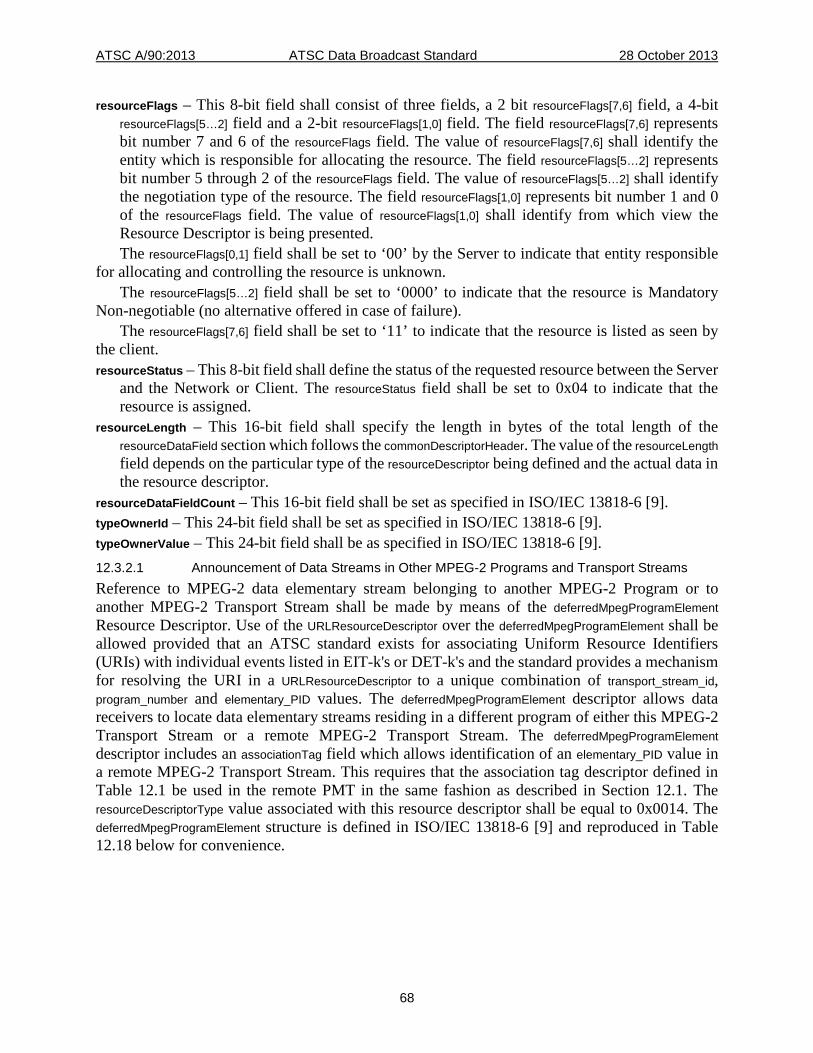
ATSC A/90:2013 ATSC Data Broadcast Standard 28 October 2013
68
resourceFlags – This 8-bit field shall consist of three fields, a 2 bit resourceFlags[7,6] field, a 4-bit resourceFlags[5…2] field and a 2-bit resourceFlags[1,0] field. The field resourceFlags[7,6] represents bit number 7 and 6 of the resourceFlags field. The value of resourceFlags[7,6] shall identify the entity which is responsible for allocating the resource. The field resourceFlags[5…2] represents bit number 5 through 2 of the resourceFlags field. The value of resourceFlags[5…2] shall identify the negotiation type of the resource. The field resourceFlags[1,0] represents bit number 1 and 0 of the resourceFlags field. The value of resourceFlags[1,0] shall identify from which view the Resource Descriptor is being presented. The resourceFlags[0,1] field shall be set to ‘00’ by the Server to indicate that entity responsible
for allocating and controlling the resource is unknown. The resourceFlags[5…2] field shall be set to ‘0000’ to indicate that the resource is Mandatory
Non-negotiable (no alternative offered in case of failure). The resourceFlags[7,6] field shall be set to ‘11’ to indicate that the resource is listed as seen by
the client. resourceStatus – This 8-bit field shall define the status of the requested resource between the Server
and the Network or Client. The resourceStatus field shall be set to 0x04 to indicate that the resource is assigned.
resourceLength – This 16-bit field shall specify the length in bytes of the total length of the resourceDataField section which follows the commonDescriptorHeader. The value of the resourceLength field depends on the particular type of the resourceDescriptor being defined and the actual data in the resource descriptor.
resourceDataFieldCount – This 16-bit field shall be set as specified in ISO/IEC 13818-6 [9]. typeOwnerId – This 24-bit field shall be set as specified in ISO/IEC 13818-6 [9]. typeOwnerValue – This 24-bit field shall be as specified in ISO/IEC 13818-6 [9]. 12.3.2.1 Announcement of Data Streams in Other MPEG-2 Programs and Transport Streams Reference to MPEG-2 data elementary stream belonging to another MPEG-2 Program or to another MPEG-2 Transport Stream shall be made by means of the deferredMpegProgramElement Resource Descriptor. Use of the URLResourceDescriptor over the deferredMpegProgramElement shall be allowed provided that an ATSC standard exists for associating Uniform Resource Identifiers (URIs) with individual events listed in EIT-k's or DET-k's and the standard provides a mechanism for resolving the URI in a URLResourceDescriptor to a unique combination of transport_stream_id, program_number and elementary_PID values. The deferredMpegProgramElement descriptor allows data receivers to locate data elementary streams residing in a different program of either this MPEG-2 Transport Stream or a remote MPEG-2 Transport Stream. The deferredMpegProgramElement descriptor includes an associationTag field which allows identification of an elementary_PID value in a remote MPEG-2 Transport Stream. This requires that the association tag descriptor defined in Table 12.1 be used in the remote PMT in the same fashion as described in Section 12.1. The resourceDescriptorType value associated with this resource descriptor shall be equal to 0x0014. The deferredMpegProgramElement structure is defined in ISO/IEC 13818-6 [9] and reproduced in Table 12.18 below for convenience.
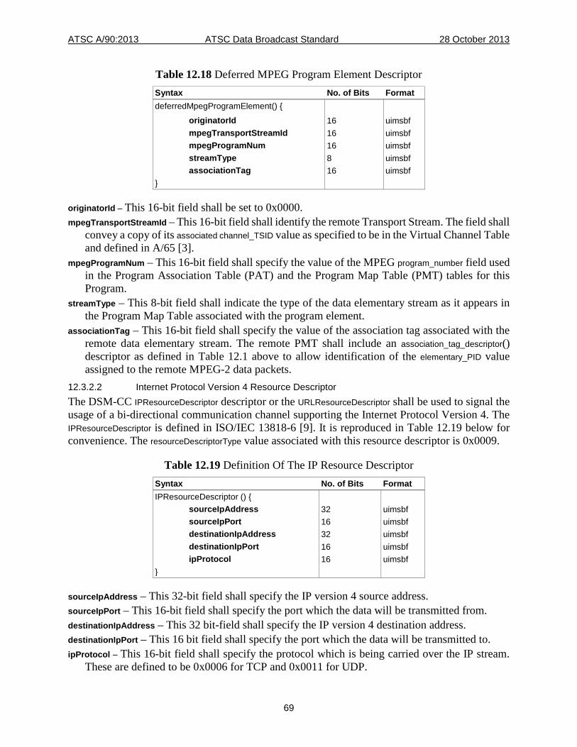
ATSC A/90:2013 ATSC Data Broadcast Standard 28 October 2013
69
Table 12.18 Deferred MPEG Program Element Descriptor Syntax No. of Bits Format deferredMpegProgramElement() { originatorId 16 uimsbf mpegTransportStreamId 16 uimsbf mpegProgramNum 16 uimsbf streamType 8 uimsbf associationTag 16 uimsbf }
originatorId – This 16-bit field shall be set to 0x0000. mpegTransportStreamId – This 16-bit field shall identify the remote Transport Stream. The field shall
convey a copy of its associated channel_TSID value as specified to be in the Virtual Channel Table and defined in A/65 [3].
mpegProgramNum – This 16-bit field shall specify the value of the MPEG program_number field used in the Program Association Table (PAT) and the Program Map Table (PMT) tables for this Program.
streamType – This 8-bit field shall indicate the type of the data elementary stream as it appears in the Program Map Table associated with the program element.
associationTag – This 16-bit field shall specify the value of the association tag associated with the remote data elementary stream. The remote PMT shall include an association_tag_descriptor() descriptor as defined in Table 12.1 above to allow identification of the elementary_PID value assigned to the remote MPEG-2 data packets.
12.3.2.2 Internet Protocol Version 4 Resource Descriptor The DSM-CC IPResourceDescriptor descriptor or the URLResourceDescriptor shall be used to signal the usage of a bi-directional communication channel supporting the Internet Protocol Version 4. The IPResourceDescriptor is defined in ISO/IEC 13818-6 [9]. It is reproduced in Table 12.19 below for convenience. The resourceDescriptorType value associated with this resource descriptor is 0x0009.
Table 12.19 Definition Of The IP Resource Descriptor Syntax No. of Bits Format IPResourceDescriptor () { sourceIpAddress 32 uimsbf sourceIpPort 16 uimsbf destinationIpAddress 32 uimsbf destinationIpPort 16 uimsbf ipProtocol 16 uimsbf }
sourceIpAddress – This 32-bit field shall specify the IP version 4 source address. sourceIpPort – This 16-bit field shall specify the port which the data will be transmitted from. destinationIpAddress – This 32 bit-field shall specify the IP version 4 destination address. destinationIpPort – This 16 bit field shall specify the port which the data will be transmitted to. ipProtocol – This 16-bit field shall specify the protocol which is being carried over the IP stream.
These are defined to be 0x0006 for TCP and 0x0011 for UDP.
ATSC A/90:2013 ATSC Data Broadcast Standard 28 October 2013
70
12.3.2.3 Internet Protocol Version 6 Resource Descriptor The DSM-CC IPV6ResourceDescriptor descriptor or the URLResourceDescriptor descriptor shall be used to signal the usage of a bi-directional communication channel supporting the Internet Protocol Version 6. The IPV6ResourceDescriptor is defined in ISO/IEC 13818-6 [9]. It is reproduced in Table 12.20 below for convenience. The resourceDescriptorType value associated with this resource descriptor is 0x0015.
Table 12.20 Definition of the IPV6 Resource Descriptor Syntax No. of Bits Format IPV6ResourceDescriptor () { sourceIpV6Address 128 nbomsbf sourceIpV6Port 16 nbomsbf destinationIpV6Address 128 nbomsbf destinationIpV6Port 16 nbomsbf ipV6Protocol 16 uimsbf }
sourceIpV6Address – This 128-bit field shall specify the IP version 6 source address. A value equal to 0 shall indicate that this is not a valid IP address.
sourceIpV6Port – This 16-bit field shall specify the port which the data will be transmitted from. destinationIpV6Address – This 128 bit-field shall specify the IP version 6 destination address. destinationIpV6Port – This 16-bit field shall specify the port which the data will be transmitted to. ipV6Protocol – This 16-bit field shall specify the protocol which is being carried over the IP
stream.These are defined to be 0x0006 for TCP and 0x0011 for UDP. The sourceIpV6Address, sourceIpV6Port, destinationIpV6Address and destinationIpV6Port fields shall be
transmitted as uimsbf bytes and following a Network Byte Order (most significant byte transmitted first). 12.3.2.4 URL Resource Descriptor The DSM-CC URLResourceDescriptor descriptor may be used to signal the usage of a resource defined by a Uniform Resource Locator (URL). The only alternative method for signaling a communication channel supporting either Internet Protocol Version 4 or 6 shall be to use an IPResourceDescriptor or an IPV6ResourceDescriptor, respectively. Use of the URLResourceDescriptor over the deferredProgramElement shall be allowed provided the condition that an ATSC standard exists for associating Uniform Resource Identifiers (URIs) with individual events listed in EIT-k's or DET-k's and the standard provides a mechanism for resolving the URI in a URLResourceDescriptor to a unique combination of transport_stream_id, program_number and elementary_PID values.
The URLResourceDescriptor is defined in ISO/IEC 13818-6 [9]. It is reproduced in Table 12.21 for convenience. The resourceDescriptorType value associated with this resource descriptor is 0x0016.
ATSC A/90:2013 ATSC Data Broadcast Standard 28 October 2013
71
Table 12.21 URL Resource Descriptor Definition Syntax No of Bits Format URLResourceDescriptor() { URL_length 16 uimsbf for (i=0; i<URL_length; i++) { URL_byte 8 bslbf } }
URL_length – This 16-bit field shall specify the length in bytes of the URL string. URL_byte – This 8-bit field shall represent a byte of the URL string.
13. SYSTEM TARGET DECODER MODEL Delivery of data elementary streams shall be subject to the Transport System Target Decoder (T-STD) buffer model specified in this section. The buffer model for asynchronous, synchronous and synchronized data elementary streams shall include a Transport Buffer and a Smoothing Buffer as defined in ISO/IEC 13818-1 [8]. The buffer model associated with a program element conveying Service Description Framework data shall be the same as the one used for asynchronous data elementary streams. The buffer parameters for asynchronous and synchronized data elementary streams are specified in Section 13.1. In addition, the buffer model for synchronized data broadcast services shall include a Data Elementary Stream buffer defined in Section 13.2. This section also specifies the descriptors informing a data receiver of the smoothing buffer model requirements.
13.1 Smoothing Buffer Descriptor The value of sb_leak and sb_size shall be the values defined by the data_service_profile field in the data_service_descriptor. If the smoothing buffer descriptor descriptor is included, the values of the sb_leak and sb_size fields shall be less than or equal to the values indicated by the data_service_profile.
The values assigned to the descriptors associated with the smoothing buffer SBn requirements shall be specific for each data service or individual data elementary stream within a service. The following parameters shall be used to constrain the data broadcast service’s buffering requirements:
• The sb_size and sb_leak_rate fields of the smoothing_buffer_descriptor defined in ISO/IEC 13818-1 [8],
• The maximum_bitrate field of the maximum_bit_rate descriptor defined in ISO/IEC 13818-1 [8], and
• The data_service_profile field in the data_service_descriptor.
Figure 13.1 defines the Transport Buffer and Smoothing Buffer configuration used in the System Target Decoder buffer model.
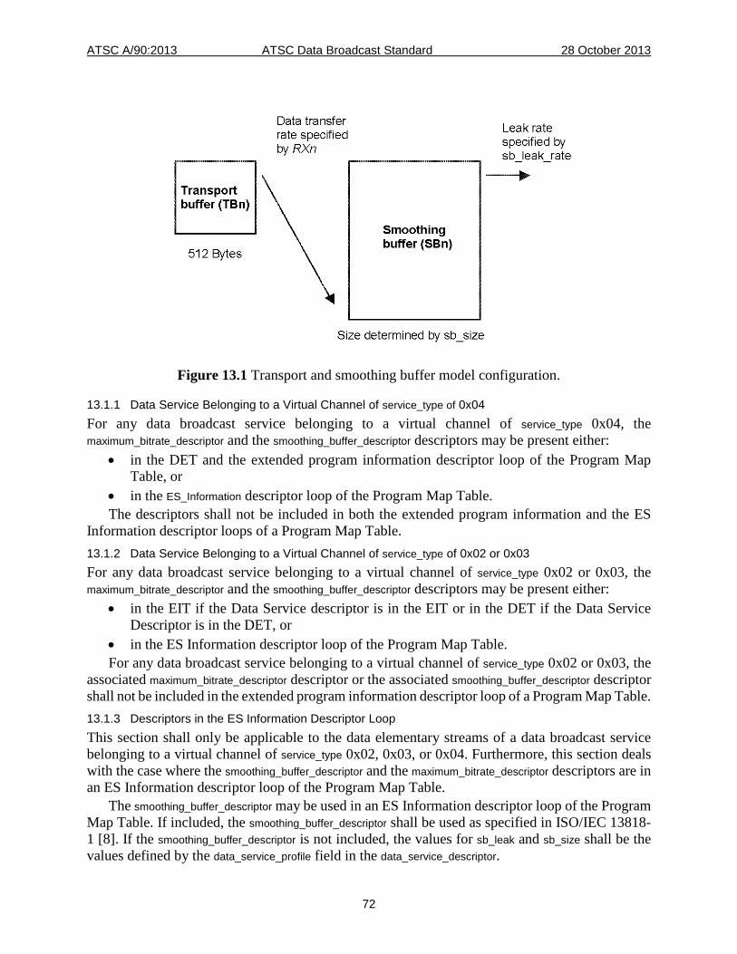
ATSC A/90:2013 ATSC Data Broadcast Standard 28 October 2013
72
Figure 13.1 Transport and smoothing buffer model configuration.
13.1.1 Data Service Belonging to a Virtual Channel of service_type of 0x04 For any data broadcast service belonging to a virtual channel of service_type 0x04, the maximum_bitrate_descriptor and the smoothing_buffer_descriptor descriptors may be present either:
• in the DET and the extended program information descriptor loop of the Program Map Table, or
• in the ES_Information descriptor loop of the Program Map Table. The descriptors shall not be included in both the extended program information and the ES
Information descriptor loops of a Program Map Table. 13.1.2 Data Service Belonging to a Virtual Channel of service_type of 0x02 or 0x03 For any data broadcast service belonging to a virtual channel of service_type 0x02 or 0x03, the maximum_bitrate_descriptor and the smoothing_buffer_descriptor descriptors may be present either:
• in the EIT if the Data Service descriptor is in the EIT or in the DET if the Data Service Descriptor is in the DET, or
• in the ES Information descriptor loop of the Program Map Table. For any data broadcast service belonging to a virtual channel of service_type 0x02 or 0x03, the
associated maximum_bitrate_descriptor descriptor or the associated smoothing_buffer_descriptor descriptor shall not be included in the extended program information descriptor loop of a Program Map Table. 13.1.3 Descriptors in the ES Information Descriptor Loop This section shall only be applicable to the data elementary streams of a data broadcast service belonging to a virtual channel of service_type 0x02, 0x03, or 0x04. Furthermore, this section deals with the case where the smoothing_buffer_descriptor and the maximum_bitrate_descriptor descriptors are in an ES Information descriptor loop of the Program Map Table.
The smoothing_buffer_descriptor may be used in an ES Information descriptor loop of the Program Map Table. If included, the smoothing_buffer_descriptor shall be used as specified in ISO/IEC 13818-1 [8]. If the smoothing_buffer_descriptor is not included, the values for sb_leak and sb_size shall be the values defined by the data_service_profile field in the data_service_descriptor.
ATSC A/90:2013 ATSC Data Broadcast Standard 28 October 2013
73
The maximum_bitrate_descriptor may be used in the ES Information descriptor loop of the Program Map Table. If included, the maximum_bitrate_descriptor shall be used as specified in ISO/IEC 13818-1 [8] and the value of the maximum_bitrate field shall be such that the corresponding bit rate is not greater than the bit rate value defined by the data_service_profile field in the data_service_descriptor. If the maximum_bitrate_descriptor is not included, the value for maximum_bitrate shall be the value defined by the data_service_profile field in the data_service_descriptor. 13.1.4 Descriptors in the Extended Program Information Descriptor Loop This section shall be applicable to a data broadcast service belonging only to a virtual channel of service_type 0x04. Furthermore, this section deals with the case where the smoothing_buffer_descriptor and the maximum_bitrate_descriptor descriptors are in the Program Information descriptor loop of the Program Map Table.
The smoothing_buffer_descriptor descriptor(s) may be used in the Program Information descriptor loop of the Program Map Table. If included, the smoothing_buffer_descriptor shall be used as specified in ISO/IEC 13818-1 [8]. If the smoothing_buffer_descriptor is not included, the values for sb_leak and sb_size shall be the values defined by the data_service_profile field in the data_service_descriptor.
The maximum_bitrate_descriptor descriptor may be used in the Program Information descriptor loop of the Program Map Table. If included, the maximum_bitrate_descriptor shall be used as specified in ISO/IEC 13818-1 [8] and the value of the maximum_bitrate field shall be such that the corresponding bit rate is not greater than the bit rate value defined by the data_service_profile field in the data_service_descriptor. If the maximum_bitrate_descriptor is not included, the value for maximum_bitrate shall be the value defined by the data_service_profile field in the data_service_descriptor. 13.1.5 Buffering This section addresses the characteristics of the hypothetical T-STD model for asynchronous, synchronous and synchronized data elementary streams.
Complete Transport packets containing data from data elementary stream n, as indicated by its PID, are passed to the transport buffer for stream n, TBn. This includes duplicate transport streams packets and packets with no payloads. Transfer of any byte from the System Target Decoder input to TBn is considered instantaneous. The size of TBn, TBSn, shall be equal to 512 bytes.
All bytes that enter the buffer TBn are removed at the rate RXn. Bytes that are part of a PES packet or a DST section or a NRT section or a DSM-CC section or a DSM-CC addressable section are delivered to the Smoothing buffer SBn. Other bytes are not and may be used to control the system. Duplicate Transport Stream packets are not delivered to SBn. The buffer TBn is emptied at the rate RXn = 1.2 Rmax[ data service profile ], where Rmax [ data service profile ] is the maximum data rate associated with the data service profile as specified in Table 11.5 of this standard. The Transport buffer TBn shall not overflow.
If there is data in buffer SBn, the data is taken out of SBn at a rate specified by sb_leak. The default sb_leak values are specified in Section 11.5 of this standard. The buffer SBn shall not be allowed to overflow.
13.2 Buffer Model for Synchronized Data Services A Data Elementary Buffer (DEBn) shall be used to ensure the timely and controlled delivery of synchronized data services to a target receiver. Input to this buffer shall be the bytes originating from the smoothing buffer SBn shown in Figure 13.1. The overall System Target Decoder model for synchronized data services is shown in Figure 13.2.
ATSC A/90:2013 ATSC Data Broadcast Standard 28 October 2013
74
13.2.1 General Constraints In the following sections, Synchronized Data Elementary Stream (SDES) shall be used to refer to either DSM-CC sections carrying non-streaming synchronized data modules or PES packets carrying streaming synchronized data payload. An SDES shall be partitioned into Data Access Units (DAUs). A Data Access Unit shall be equal to the in order concatenation of the payload of:
• one or more PES packets starting with a PES packet bearing a PTS field up to and not including the next PES packet bearing an PTS field or,
• one or more DSMCC_section sections of the same version, starting with the Section with section_number value 0 bearing a PTS field, conveying a single DSM-CC data module.
In the case of PES packets carrying streaming synchronized data, when the delivery of DAU's is discontinuous (meaning that the next PES packet bearing a PTS field would not arrive sufficiently early to cause removal of the DAU from the DEB) then an empty PES packet (bearing a PTS field and having an empty payload) shall be inserted to signal the end of the DAU.
A DAU shall include the PES header bytes or the DSMCC_section header bytes, respectively. Each DAU shall include a distinct Presentation Time Stamp. The purpose of the Presentation Time Stamp is to associate the complete DAU with a particular instant of the concurrent audio-visual event. The following sections define a buffer model for a data service consuming one or more data elementary streams of which only one is a synchronized data elementary stream. The size of the buffer DEBn (DEBSn) used for acquiring this SDES shall be specified by the value of the data_service_level field in the data_service_descriptor. If more than one SDES is used in a data service, the size DEBSn of the DEBn buffer as specified by the value of the data_service_level field in the data_service_descriptor, shall be split uniformly among all the synchronized data elementary streams used by that data service. In cases when such uniform splitting results in fractional byte allocation, the buffer size assigned to each synchronized data elementary stream shall be rounded up to the nearest integer byte size.
The Transport System Target Decoder model defined in this standard is a theoretical buffer model assuming instantaneous decoding. Multiplexer and receiver implementations will have to take into account time required to parse, decode and render the data in each individual Data Access Unit. Consequently, Data Access Units in a Data Elementary Stream may have to be inserted in an ISO/IEC 13818-1 Transport Stream with a pre-specified time advance. In turn, data receivers may elect to take a DAU out of the DEBn buffer at an earlier time depending on its own parsing, decoding and rendering capability in order to achieve synchronization. 13.2.2 Data Elementary Stream Buffer for Synchronized Services This section addresses the characteristics and additional constraints of the hypothetical T-STD model for synchronized data elementary streams.
All bytes at the output of the smoothing buffer SBn, associated with a synchronized data elementary stream denoted by index n, are passed to the Data Elementary Buffer, referred to as DEBn. If there is PES packet or DSM-CC section data in SBn and buffer DEBn is not full, the data is transferred from SBn to DEBn at a rate defined by sb_leak. During the transfer from SBn to DEBn, bytes from either the PES packet header or DSMCC_section header may be used to control the system and are then discarded. If DEBn is full, data are not removed from SBn. When there is no PES packet or DSM-CC section in SBn, no data is removed from SBn. The buffer DEBn shall not be allowed to overflow.
The Presentation Time ‘tpn’ is specified by the PTS field of the DAU. For the Data Elementary Buffer DEBn, all data for the Data Access Unit that has been in the buffer longest are removed
ATSC A/90:2013 ATSC Data Broadcast Standard 28 October 2013
75
instantaneously at time ‘tpn’ assuming instantaneous decoding. In the case of a non-streaming, synchronized data elementary stream (stream_type 0x14) or in the case of a streaming synchronized data elementary stream (stream_type 0x06), the buffer DEBn shall not underflow when a Data Access Unit is removed from the buffer at its associated decoding time. 13.2.3 Minimum Elementary Stream Buffer Size The minimal value for DEBSn shall be equal to 120120 bytes. This buffer size corresponds to three times the maximum amount of data that can be transmitted in 1/60 * 1000/1001 of a second at a 19.2 Mbits/sec data transfer rate (largest possible data rate). The assumption is made that a nominal DAU size corresponds to the maximum number of bytes that can be transmitted in 1/60th of a second. The size of a nominal DAU is therefore equal to 19.2 Mbits/sec * 1001 / (8 * 60 * 1000) = 40040 bytes and the nominal Data Access Units frequency is 59.94 Hz. The data conveyed in a nominal DAU can therefore be viewed as being in association with a particular DTV video field. The purpose of defining a nominal Data Access Unit is to provide a reference point to the specification of Data Elementary Stream Buffer size. The size of the Data Elementary Stream Buffer is such that it can hold up to three nominal Data Access Units. Such a choice for DEBSn allows for one nominal DAU to be flushed out of the buffer while a second re-assembled nominal DAU is held ready and a third nominal DAU is being acquired.
Data Access Units shall be separated in time by no less than 5.561111 milliseconds (corresponding to a Data Access Unit frequency of 3 times the nominal Data Access Unit frequency). 13.2.4 Buffer Sizes and Data Service Levels This section defines the concept of data service levels. A Data Service level is specific to a particular value of DEBSn, the size of the data elementary stream buffer. A level 1 data service shall correspond to an DEBSn size equal to 120120 bytes as described in the previous section. The Level 4, Level 16 and Level 64 data services are defined in term of the level 1 DEBSn value as follows: Level 1 (multiplicative factor is equal to 1) shall signal a DEBSn value equal to120120 bytes. Level 4 (multiplicative factor is equal to 4) shall signal a DEBSn value equal to 480480 bytes. Level 16 (multiplicative factor is equal to 16) shall signal a DEBSn value equal to 1921920 bytes. Level 64 (multiplicative factor is equal to 64) shall signal a DEBSn value equal to 7687680 bytes.
The nominal Data Access Unit size for level 1, level 4, level 16 and level 64 shall be 40040 bytes, 160160 bytes, 640640 bytes and 2562560 bytes, respectively.
The value of the data service level shall be signaled in the data_service_descriptor. 13.2.5 Buffer Arrangement Figure 13.2 below illustrates the buffer arrangement for synchronized data services. The size of the Transport Buffer TBn shall be equal to 512 bytes. The size and leak rate of the smoothing buffer SBn shall specified by sb_size and sb_leak_rate, respectively. The Data Access Units are input to the Data Elementary Buffer DEBn. In accordance with the T-STD model, the Data Access Units are taken out of the Data Elementary Buffer instantaneously and at presentation time ‘tpn’ 'specified in the PTS field of the DAU.
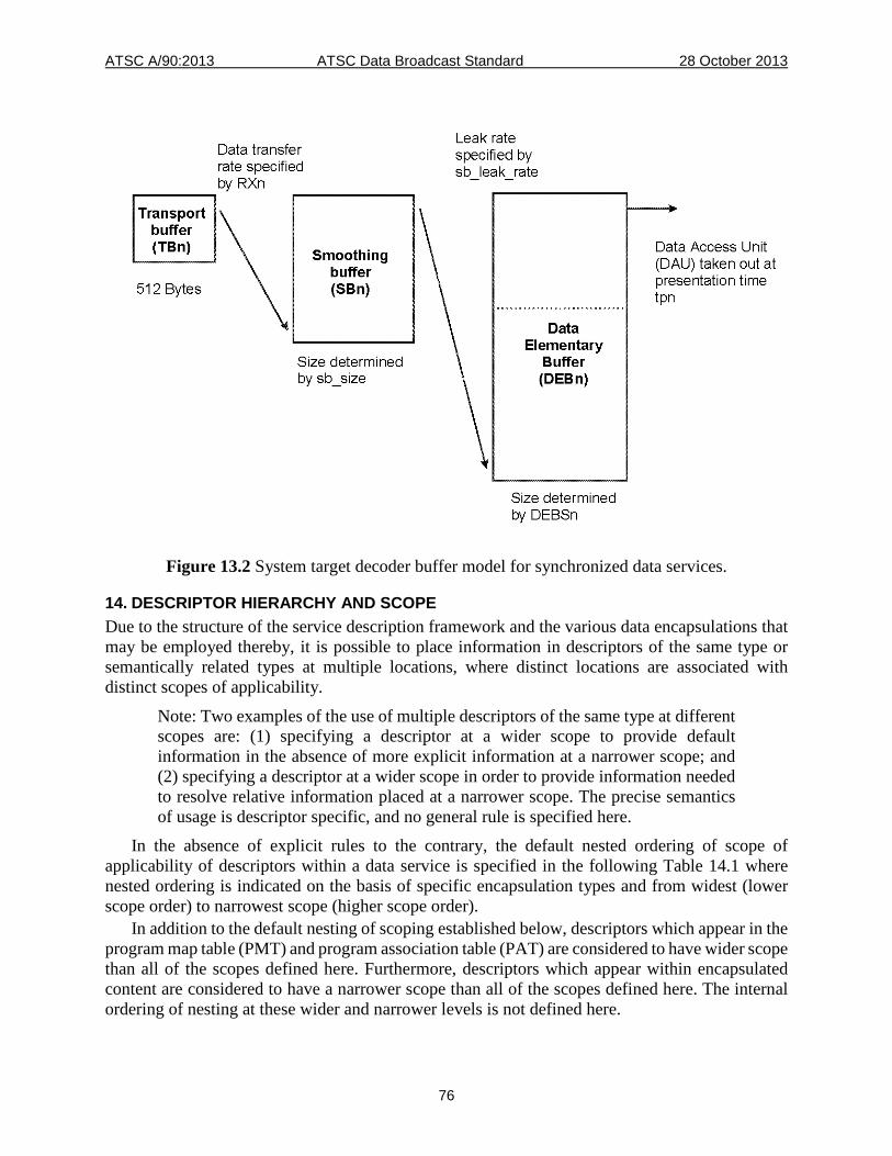
ATSC A/90:2013 ATSC Data Broadcast Standard 28 October 2013
76
Figure 13.2 System target decoder buffer model for synchronized data services.
14. DESCRIPTOR HIERARCHY AND SCOPE Due to the structure of the service description framework and the various data encapsulations that may be employed thereby, it is possible to place information in descriptors of the same type or semantically related types at multiple locations, where distinct locations are associated with distinct scopes of applicability.
Note: Two examples of the use of multiple descriptors of the same type at different scopes are: (1) specifying a descriptor at a wider scope to provide default information in the absence of more explicit information at a narrower scope; and (2) specifying a descriptor at a wider scope in order to provide information needed to resolve relative information placed at a narrower scope. The precise semantics of usage is descriptor specific, and no general rule is specified here.
In the absence of explicit rules to the contrary, the default nested ordering of scope of applicability of descriptors within a data service is specified in the following Table 14.1 where nested ordering is indicated on the basis of specific encapsulation types and from widest (lower scope order) to narrowest scope (higher scope order).
In addition to the default nesting of scoping established below, descriptors which appear in the program map table (PMT) and program association table (PAT) are considered to have wider scope than all of the scopes defined here. Furthermore, descriptors which appear within encapsulated content are considered to have a narrower scope than all of the scopes defined here. The internal ordering of nesting at these wider and narrower levels is not defined here.
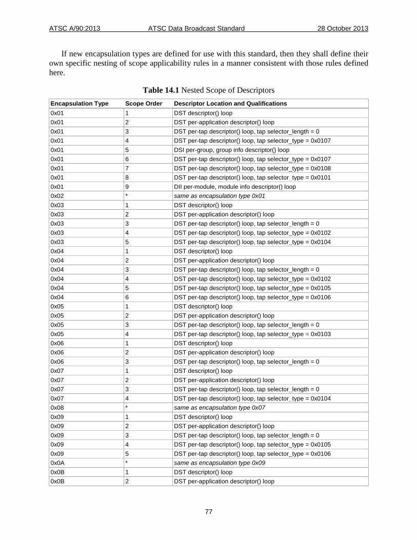
ATSC A/90:2013 ATSC Data Broadcast Standard 28 October 2013
77
If new encapsulation types are defined for use with this standard, then they shall define their own specific nesting of scope applicability rules in a manner consistent with those rules defined here.
Table 14.1 Nested Scope of Descriptors Encapsulation Type Scope Order Descriptor Location and Qualifications 0x01 1 DST descriptor() loop 0x01 2 DST per-application descriptor() loop 0x01 3 DST per-tap descriptor() loop, tap selector_length = 0 0x01 4 DST per-tap descriptor() loop, tap selector_type = 0x0107 0x01 5 DSI per-group, group info descriptor() loop 0x01 6 DST per-tap descriptor() loop, tap selector_type = 0x0107 0x01 7 DST per-tap descriptor() loop, tap selector_type = 0x0108 0x01 8 DST per-tap descriptor() loop, tap selector_type = 0x0101 0x01 9 DII per-module, module info descriptor() loop 0x02 * same as encapsulation type 0x01 0x03 1 DST descriptor() loop 0x03 2 DST per-application descriptor() loop 0x03 3 DST per-tap descriptor() loop, tap selector_length = 0 0x03 4 DST per-tap descriptor() loop, tap selector_type = 0x0102 0x03 5 DST per-tap descriptor() loop, tap selector_type = 0x0104 0x04 1 DST descriptor() loop 0x04 2 DST per-application descriptor() loop 0x04 3 DST per-tap descriptor() loop, tap selector_length = 0 0x04 4 DST per-tap descriptor() loop, tap selector_type = 0x0102 0x04 5 DST per-tap descriptor() loop, tap selector_type = 0x0105 0x04 6 DST per-tap descriptor() loop, tap selector_type = 0x0106 0x05 1 DST descriptor() loop 0x05 2 DST per-application descriptor() loop 0x05 3 DST per-tap descriptor() loop, tap selector_length = 0 0x05 4 DST per-tap descriptor() loop, tap selector_type = 0x0103 0x06 1 DST descriptor() loop 0x06 2 DST per-application descriptor() loop 0x06 3 DST per-tap descriptor() loop, tap selector_length = 0 0x07 1 DST descriptor() loop 0x07 2 DST per-application descriptor() loop 0x07 3 DST per-tap descriptor() loop, tap selector_length = 0 0x07 4 DST per-tap descriptor() loop, tap selector_type = 0x0104 0x08 * same as encapsulation type 0x07 0x09 1 DST descriptor() loop 0x09 2 DST per-application descriptor() loop 0x09 3 DST per-tap descriptor() loop, tap selector_length = 0 0x09 4 DST per-tap descriptor() loop, tap selector_type = 0x0105 0x09 5 DST per-tap descriptor() loop, tap selector_type = 0x0106 0x0A * same as encapsulation type 0x09 0x0B 1 DST descriptor() loop 0x0B 2 DST per-application descriptor() loop
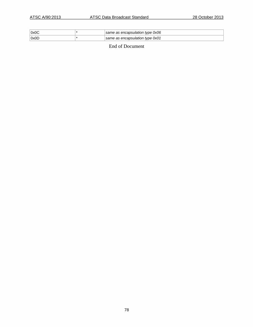
ATSC A/90:2013 ATSC Data Broadcast Standard 28 October 2013
78
0x0C * same as encapsulation type 0x06 0x0D * same as encapsulation type 0x01
End of Document