atmospheric water vapor differential absorption measurements on vertical paths with a co_2 lidar
TRANSCRIPT

Atmospheric water vapor differential absorption measurementson vertical paths with a CO2 lidar
P. W. Baker
Ground based vertical path differential absorption measurements were obtained up to a height of 1.5 kmwith a CO2 lidar transmitting alternatively on the R(20) (10.247-Am) and R(18) (10.260-,um) lines duringdaylight in conditions of both strong and weak temperature inversions. The differential absorption betweenthese lines for typical middle latitude lower atmosphere water vapor concentrations appears to be well suitedto this type of measurement as the power loss on the more absorbed backscattered line [R(20)] is not toogreat as to unduly restrict the operating range, while the power differential is still sufficiently large to bereadily measureable. In one set of measurements a strong temperature inversion at a height of 1 km resultedin a rapid vertical lapse in aerosol concentration with a consequent loss of SNR on the returns and severe dis-tortion to the differential absorption profiles at this level. Water vapor profiles were derived from all mea-surements except in the region of the strong temperature inversion where the atmospheric backscatteringcross section decayed rapidly. Reasonable results were obtained through the weak inversion region. Themeasurement capability of the lidar was found to be restricted by the length of the laser pulse tail and an in-adequate signal-to-noise performance in regions of strong temperature inversions due to the associated de-creases in aerosol concentration.
1. Introduction
The use of lidar measurements of the differentialabsorption due to a single absorbing atmosphericspecies to determine its concentration is now well es-tablished. Estimates have been made of atmosphericwater vapor content in the visible to IR region.1-3 AtCO2 wavelengths both water vapor3 and ozone4 havebeen measured. However, no measurements havepreviously been reported in which the CO2 lidar wasused for vertical differential absorption and water vapormeasurements.
The average vapor pressure of the absorbing molec-ular species over the height interval AH is given by1
e(H+ 4A 1 )= 1 {log [PABH +A~H] -log PB(H)11 (1)2 2 _ 1 I [P_,(H_ 1 [PA(H)]
where e(H + AH/2) = average vapor pressure of theabsorbing gas (atmospheres)in the height interval H to H +AH;
PA (H) = backscattered power (watts) atthe wavelength A, sufferingthe lesser absorption, from theinterval H - AH/2 to H +AH/2;
The author is with Department of Defence, Electronics ResearchLaboratory, Salisbury, South Australia 5108.
Received 15 April 1983.0003-6935/83/152257-08$01.00/0.© 1983 Optical Society of America.
PB (H) = backscattered power (watts) atthe wavelength B from theheight interval H - AH/2 to H+ AH/2; and
AK = KA - KA, where KB and KBare the absorption coefficientsof the absorbing molecularspecies at the two wavelengths(m-l atm-1).
In the derivation of Eq. (1) it has been assumed thatthe differences in the extinction and backscatteringcoefficients at the two wavelengths A and B are negli-gible. This is a reasonable approximation for the CO2line pairs employed in the measurements reported here.It has also been assumed that the absorption effects byother gases are negligible. Errors arising from thewavelength dependence of scintillations are negligibleover the small wavelength range employed in this ex-periment.
II. CO 2 Lidar System
A schematic diagram of the lidar is shown in Fig. 1.A concave lens was employed to focus the far field imageof the telescope on the detector. It was necessary toperform a logarithmic amplification on the detectedsignal because the analog-to-digital converter (ADC)was limited to a six-bit range. With this addition it waspossible to sample over an 80-dB electrical range. (Thiseffectively meant a 40-dB optical range because thedetector output voltage was proportional to the incidentoptical power.) However, the increase in dynamic range
1 August 1983 / Vol. 22, No. 15 / APPLIED OPTICS 2257

was gained at the expense of resolution which was cali-brated for each step of the ADC and had a value of 0.55dB at the center of its operating range. A small part ofthe laser pulse was deflected onto a pyroelectric detec-tor, and the integrated output was switched in place ofthe telescope signal to the ADC after the backscatteredpulse return had decayed below the receiver noiselevel.
The laser was operated in the fundamental transversemode by employing an unstable resonator as the frontmirror of the cavity. The alignment of the laser andtelescope was achieved by using a large mirror at rooflevel to reflect the optical axis through 90°, and bothlaser and telescope were centered on a target at a dis-tance of 450 m.
The system parameters of the CO2 lidar are given inTable I.
Ill. Range Resolution and Signal-to-NoiseConsiderations
When the TEA laser was operated at low pulse energylevels, by using the appropriate gas mixture, a shortpulse was obtained. The pulse had a sharp leading edge(with a rise time of -50 nsec) and exponentiallydecaying tail which took -100 nsec to decay to a valueof exp(-1) of the peak value. At much higher pulseenergy levels the rise time was the same, but the decayinterval [to exp(-1)] increased to 1 ,usec. This hadimportant implications for the differential absorptionmeasurements because to obtain good signal-to-noisereturns from moderate altitudes (i.e., 1 km) it was nec-essary to transmit at the highest laser pulse energy.However, the associated long pulse emitted at highenergies meant that significant backscattered power inthe tail of the pulse was received at the same time as thecontribution from the leading edge. The severity of theinterference from the pulse tail was dependent on thebackscattering aerosol density profile. It was mini-mized when the aerosol density profile had a slow heightdecay.
The effect of pulse length on the differential ab-sorption can be seen with the following simple model.
The laser pulse at time t is represented by a sharpleading edge followed by an exponential decay of theform exp(-t/TAU), with time constant TAU, so thatwhen the leading edge is returned from a height H apoint on the trailing edge of the pulse at X, corre-sponding to a time interval 2(H - X)/C, will arrive backat the receiver at the same time as the leading edge. Cis the velocity of light. The total energy received at agiven instant from all backscattered components of thepulse is proportional tofH1 e 2(H-X)j I x
Jx=o TAUC
exp (-2KB £b edZ)/X2dX, (2)
where HS is the scale height of the aerosol density andKB is the absorption coefficient of water vapor on theabsorbed wavelength emission. Combining this ex-pression with one for the unabsorbed transmission (KA
Fig. 1. Schematic diagram of lidar and recording system.
Table I. CO2 Lidar Parameters
CO2 TEA laserTransmitted energy:(a) Maximum(b) Without N2 in gas mixLines (10-,um band)Pulse width:(a) to exp(-1) level(b) to exp(-1) levelBeam divergenceTypical prfMaximum prf
ReceiverTelescope:DiameterField of viewHg-Cd-Te photoconductivedetectorD*Time constantSize
'9
I
:S
4J0.1JR (18),R (20)
1 ,usec100 nsec1 X 0.6 mrad0.07 Hz0.5 Hz
30 cm1 mrad
3 X 1010 cm Hz/W50 nsec1 X lmm
Fig. 2. Predicted differential absorption, R(18)-R(20), vs height forpulse lengths representative of CO2 laser output for a scale height HS
of 500 m.
2258 APPLIED OPTICS / Vol. 22, No. 15 / 1 August 1983
-

= 0), and assuming the same backscattering coefficient,yields the ratio
exp -7-A -exp (H) exp (2KB f edZ)/X2dX
{H [2(H - X)Jexp TAU C]
At heights of <100 m the inverse height dependenceshown in the above equation was replaced by a linearlyincreasing function whose value was zero at zero heightand equal to X-2 at a height of 50 m. This allows formasking effects on the telescope in this region and alsoclosely predicts the actual returned power distributionas a function of height.
This expression has been evaluated numerically forseveral values of the pulse length TAU and a scaleheight HS of 500 m. The water vapor pressure wasassumed to be 9.65 mbars up to a height of 1 km andzero at greater heights. This was at typical surfacevalue during the period of the measurements describedin Secs. IV-VI. The curves in Fig. 2 show the reductionin the returned power differential (in decibels) at lowerheights as the pulse length is increased. Pulse lengthsof 30 and 300 in are representative of the CO2 laser'sshort and long pulses, respectively.
Figure 2 illustrates that as the pulse length is in-creased the height at which the full differential ab-sorption is reached (due to the water vapor slab) isprogressively delayed.
IV. Differential Absorption Measurements for 3-12-81
When two laser beams of different wavelengthpropagate through a region of nonvarying water vaporpressure, and if one beam suffers a greater absorption,the differential absorption between the two wavelengthsexhibits a linear increase with range. If the beamssubsequently pass into a region of zero water vaporcontent there is no further change in the differentialabsorption. The type of water vapor profile which givesrise to a differential absorption characteristic of thistype occurs frequently in the presence of a temperatureinversion where the upward diffusion of water vaporfrom the earth's surface is trapped below the inversionlevel. It was, therefore, of considerable interest to seeif a water vapor profile with a sharp cutoff could bemeasured with the differential absorption technique.The local radiosonde flight for 0950 3-12-81 centralsummer time (CST) shown in Fig. 3 indicated that at-mospheric conditions were suitable for testing the lidar'sperformance as the ground based water vapor layerdryed out suddenly at 1 km just below a very strongtemperature inversion.
Differential absorption data for both the long andshort pulse operating modes were obtained within thehour following the release of the sonde (0950 CST).The laser transmitted alternatively on the R(20) andR(18) lines in the 10-Mm band every 13 sec. Thistransmission mode was adopted to minimize possibletemporal nonstationary effects in the atmosphere. Thepulse rate was determined by data recording constraints
(3)
exp ( x/X2dX
and could be speeded up to a sampling rate of 1 pulse/2sec with appropriate modifications to the recordingsystem.
The backscattered power as a function of height forthe long and short pulses are shown in Figs. 4 and 5,respectively, for both the R(18) and R(20) line pairs.The smoothed differential of the R(18) and R(20) re-turns in dB, 10 b(Hj)/log(10), shown in Fig. 6 was cal-culated as follows:
i~~ I N [lo P1 8(Hi t2k)fi(4(Hj)Z= E I log I / (nN), (4)
i=j-n k=1 P2 0 (Hi,t 2 k-1)J
where the power ratios were formed from alternativepulses received at times t2k and t2k-1, respectively.The logarithms of these ratios were averaged over Npulse pairs, and then a running mean was calculatedover n (= 11) adjacent height cells giving an effectiveheight resolution of 275 in.
The short pulse backscattered power and smootheddifferential absorption results (see Figs. 5 and 6, re-spectively) show a generally increasing absorption dif-ference up to 900 in. This is consistent with the fixedvalue of the atmospheric water vapor pressure up to thisheight. The absorption difference then only increasesmarginally in the 900-1000-m interval until it com-mences to fall at -1000 in. It seems that in this section
TEMPERATURE (C)0 20
1200
~ 800
(a) (b)
400
VAPOUR PRESSURE MBARS)
Fig. 3. Temperature (a) and water vapor pressure (b) profiles fromthe radiosonde at 0950 CST 3-12-81.
1 August 1983 / Vol. 22, No. 15 / APPLIED OPTICS 2259

40
30
am
R
3
20
10
R(20)
4..
4.
+.4
.0 . 3000
HEIGHT M
Fig. 4. Backscattered power from the long pulse sounding (65 pulsepairs) 0947-1017 CST 3-12-81.
40
30.
20
10
1000 2000 3000HEIGHT (M)
Fig. 5. Backscattered power from the short pulse sounding (63 pulsepairs) 1022-1054 CST 3-12-81.
S5.
6<
is
4
2
0
HEIGHT (M )1000
Fig. 6. Differential absorption vs height for the R(18)-R(20) linepair for the long pulse + and short pulse 0 soundings on 3-12-81.
xc e
aS
HEIGHT (I)
Fig. 7. Predicted long pulse differential absorption - together withreplot of measured values + for 3-12-81.
Table I. Water Vapor Absorption Coefficients at 300 K
AbsorptionCO2 line Wavelength (m) (km-' atm- 1 )
R(18) 10.260 381 9.65R(20) 10.246 625 86.4
2260 APPLIED OPTICS / Vol. 22, No. 15 / 1 August 1983
00000000
op * 0 +0 *+e4 .4.
0 + 0 +
e° .0
o +
0 +
o 1 +00 +
0 +
o ++
. N ........ .
b ~~~~~~~~~~~~~~~~R18) RI20)
*.4.
.,4.
.s
.4,
.4*+
a
I-
5
-
I
(900-1000 m) the absorption difference may have beendetermined by the falling SNR in the R(20) return. Asignificant feature of the short pulse R(18) backscat-tered power as a function of height (Fig. 5) was that itshowed only a small deviation from an inverse squareheight variation up to the inversion level, which indi-cated that below the inversion the aerosol density wasnearly constant. The plateau of the short pulse dif-ferential absorption curve in Fig. 6 at -900 m was dueeither to a rapid drying out of water vapor at this levelor more probably to the deterioration in the SNR.
The long pulse differential absorption results (Fig.6) illustrate the degrading effect introduced at shortranges (<500 m) by power from the tail of the pulsescattered back from heights of less than the gatedheight. The plateau commencing at-1100 was dueto the sharp decrease in aerosol density above the in-version. The shape of the long pulse curve in Fig. 6 canbe reproduced using the model introduced in Sec. IIImaking several changes to parameters. The relativeaerosol backscatter function was assumed to increaseup to 500 m and then level off before it again decreasedrapidly above the inversion. This layer is shown in Fig.7. In addition, to match the predicted curve to themeasured curve more closely it was necessary to assumethat all masking effects on the telescope were negligibleabove a height of 20 m; i.e., the inverse height depen-dence law was operative above this height. The pre-dicted curve is shown in Fig. 7 with the measured resultsreplotted for comparison. The pulse length giving thebest fit was found to be 280 m. The similarity of thesetwo curves supports the conclusion that the differentialabsorption curve below 500 m is effectively determinedby system parameters for long pulse lengths.
An extra aerosol layer which appeared during the longpulse transmission between 800 and 1000 m apparentlydid not affect the differential absoption measurementsas there is no indication of it on the curve in Fig. 6. Thisis to be expected because decreases rather than in-creases in aerosol density give rise to reductions in thepower differential between the backscattered returnsat the two wavelengths for long pulse length transmis-sions.
The sudden decrease of aerosol density at the inver-sion level prevented any further increase in the powerdifferential between the R (20) and R (18) lines at greaterheights as most of the backscattered energy came frombelow this level.
V. Water Vapor Estimates
A water vapor profile was derived from the long andshort pulse experimental results of 3-12-81 by com-bining Eqs. (1) and (4) in the form
e H =i [f) (Hj + ) - (Hj)]. (5)
The absorption coefficients for the CO2 lines R(18) andR(20) given in Table II were obtained from a best fitlinear curve to the results of Shumate et al.5 ,
6 for ab-sorption vs pressure. Although the absorption coeffi-cients KA and KB are temperature dependent, and this
O 600.
400
200
4 ' 8 ' 12 16VAPOUR PRESSURE (MBARS)
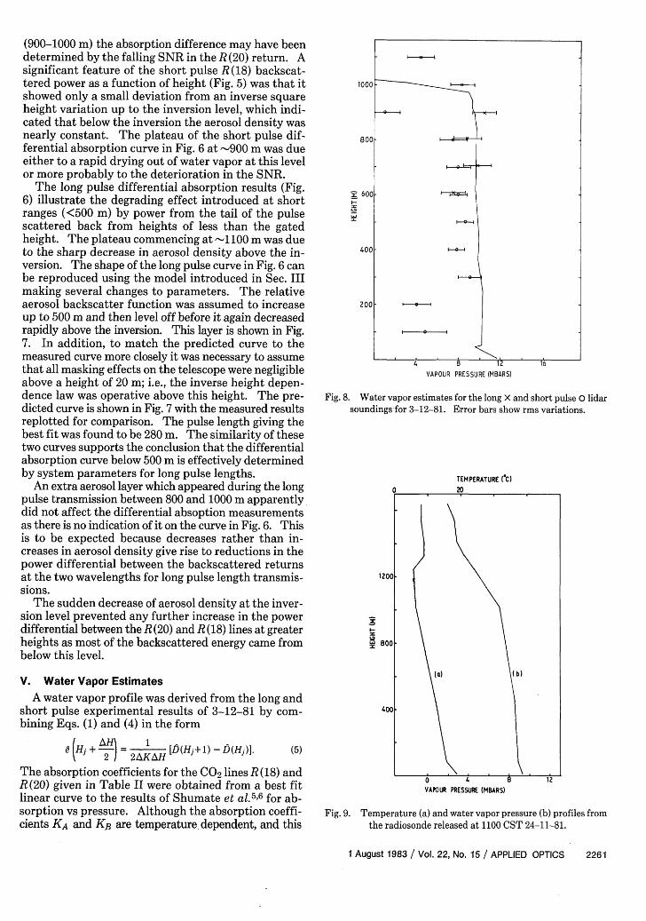
Fig. 8. Water vapor estimates for the long X and short pulse 0 lidarsoundings for 3-12-81. Error bars show rms variations.
TEMPERATURE (CI0 20
1200
A 800
(a) (~~~~b)400
0 4 8 12VAPOUR PRESSURE (MBARS)
Fig. 9. Temperature (a) and water vapor pressure (b) profiles fromthe radiosonde released at 1100 CST 24-11-81.
1 August 1983 / Vol. 22, No. 15 / APPLIED OPTICS 2261

dependence can be estimated from their semiempiricalrelationship with water vapor pressure and temperature(Peterson et al.
7), the corrections to the water vapor
estimates due to the temperature variations shown inthe profile of Fig. 3 have a maximum value of 3%, whichis most probably a smaller error than that introducedby the uncertainties in the reference values of the ab-sorption coefficients. Temperature corrections have,therefore, not been included in the present work. Theresulting water vapor estimates are shown in Fig. 8.Each point is a running mean over eleven height cells(275 i). The bars show the rms spread of the esti-mates. The vapor pressure values obtained from theshort pulse data are generally of smaller magnitude thanthose from the radiosonde and with a layer terminatingat a lower level. The low estimates at 100 and 200 mmay have been due to quantization by the ADC at lowheights where the signal level changes rapidly withdistances; this results in a stepping effect in the differ-ential absorption which is evident in Fig. 6 at an altitudeof 150 i. Profile points for the long pulse soundingabove 1100 m are not shown as they were too seriouslyaffected by the aerosol layer previously mentioned.They have also been omitted at levels below 600 m be-cause of the severity of the pulse tail distortion in thisregion.
Despite the distorting influence of the pulse tail ef-fects on the lower section of the differential absorptionvs range plot in Fig. 6, the long pulse water vapor esti-mates in the 700-1000-m height interval are quite closeto the radiosonde values. The aerosol layer appears toextend above the top of the radiosonde derived watervapor layer by -100 m. This accounts for the long pulseprofile points above 1000 m giving a significant watervapor content as is also implied by the model deriveddifferential absorption curve (Fig. 7).
VI. Results for a Weaker Temperature Inversion
Local radiosonde temperature and water vapor pro-files are plotted in Fig. 9 for 29-11-81. A temperatureinversion was evident in the 1250-1330-m height in-terval. The height gradient of the inversion on theoccasion was less severe than was observed in the resultsof 3-12-81. Since the two long pulse runs consisting of54 and 61 pulses, respectively, gave very similar resultsit was decided to average them together. The back-scattered power and differential absorption plots areshown in Figs. 10-12. The short pulse R(18) returnfollowed an inverse square law very closely indicatinga well-mixed aerosol layer up to the inversion height.At lower altitudes the long pulse differential absorptionin Fig. 12 shows similar characteristics to Fig. 5 con-firming that it is system determined. However, theplateau effect noted previously was not evident herebecause the ground based aerosol layer extended to agreater height and had a smaller decay rate through theinversion. The short pulse differential absorptionmeasurements were limited by signal-to-noise deteri-oration above 750 m.
The resulting water vapor estimates are plotted inFig. 13 together with the radiosonde profile. The short
40
30
I20
10
1000HEIGHT (M)
2000 300D
Fig. 10. Backscattered power from the long pulse sounding (115pulse pairs) 1002-1110 CST 24-11-81.
40
30laToi
20
10
1000HEIGHT (M)
2000 3000
Fig. 11. Backscattered power from the short pulse sounding (62pulse pairs) 1112 CST 24-11-81.
2262 APPLIED OPTICS / Vol. 22, No. 15 / 1 August 1983
4. R(.M
S..~~.4
-~~~~~~~C
I \
. 4..+
. 4I +
. .lf
we ~~~~~~~~~~~RI1) +R(20)
.4.
.+~~~~~~~~.4
w w -

pulse estimates appear to be affected by a pulse taileffect up to 200 m, and above this height they are sig-nificantly smaller than the radiosande measurements.The reason for this discrepancy is not known, but othersounder measurements including the long pulse esti-mates made shortly beforehand all showed betteragreement with the radiosonde data. The long pulseestimates follow the same trend as the radiosonde dataabove 700 m showing the decreasing water vapor con-tent above the 1-km height level in moderately goodagreement.
VII. Conclusions
The predicted differential absorption vs height fora CO2 lidar employing the R (20) (10.247-,um) and R (18)(10.2 6 0-Mim) lines indicates that the use of this line pairis well suited in terms of sensitivity of the differentialabsorption to typical vertical variations of water vaporin the lower atmosphere at midlatitudes for use in re-mote measurements of water vapor.
The first reported vertical path differential absorp-tion measurements with a CO2 lidar have been obtained.Both long (300-m) and short (-30-m) laser pulseswere employed. The prediction that the long pulsedifferential absorption at a given time delay is smallerthan would be obtained from the short pulse soundingdue to the larger height spread of the returns has beenexperimentally verified.
The performance of the CO2 lidar was adversely af-fected by rapid decreases in aerosol concentration neartemperature inversions with severe lapse rates with aconsequent drastic reduction in the SNR of the returnover a short height interval. This could be offset byimproving the sensitivity of the detection system.
Water vapor profiles derived from the differentialabsorption data are in general agreement with radio-sonde measurements when allowances are made for thedistortion introduced by the long tail of the transmitted
4 .4.4. ++4~~~~~~~~~~~~~~~~~~~44
z cr~~~~~~~~0~o~o° +
oo0.0 0 4. 0 +
0. ~~~00 000° + O
o ~~0 0
oO 0
0 + 0+
2 OP00 +0 4
0 4
500 1000HEIGHT (M)
Fig. 12. Differential absorption vs height for the R(18)-R(20) linepair for the long pulse + and short pulse soundings on 24-11-81.
pulse, which limited the resolution attainable from thedifferential absorption measurements. Neverthelessit has been found that reasonable accuracy is possiblein the estimation of water vapor variations up to aheight of 1.5 km provided that the ambient aerosolconcentration exhibits a smooth variation in thisrange.
The use of a short pulse length (30-m) high powerlaser (30-MW peak power) together with increaseddetection sensitivity would overcome the limitationsencountered with the present system. The detectionsensitivity was not background limited. Its thresholdsensitivity could be brought down closer to the back-ground level by cooling the first stage of the preampli-fier. If background level sensitivity were achieved, afurther improvement would be obtainable by use of anarrowband spectral filter.
This paper is published by permission of the Direc-tion, Electronics Research Laboratory. The authorwould also like to thank the following who have con-tributed to the lidar development. K. B. Whiting forcontinued support for the project. The optical systemand telescope were designed by N. Bromilow, and theconstruction was supervised by D. Anderson. Themicroprocessor based recording system was due to aninitial design by J. A. Silby and was implemented by J.C. Crombie who also developed the electronic controlsystem. The design and construction of numerouscomponents together with the initial assembly by the
1200
, 800
400
VAPOUR PRESSURE MBARS)
Fig. 13. Water vapor estimates for the long X and short pulse lidarsoundings for 24-11-81. Error bars show rms variations.
1 August 1983 / Vol. 22, No. 15 / APPLIED OPTICS 2263

lidar were due to R. Keough who also assisted with thealignment. B. A. See and M. G. Rowolle provided adviceon the optics of the laser and the suppression of elec-trical interference from the laser, respectively.
The author is presently attached to the RutherfordAppleton Laboratory, Chilton, U.K.
References1. R. M. Schotland, "The Determination of the Vertical Profile of
Atmospheric Gases by Means of a Ground Based Optical Radar,"in Proceedings, Third Symposium on Remote Sensing of theEnvironment (Environmental Research Institute of Michigan,Ann Arbor, 1964).
2. E. V. Browell, T. D. Wilkerson, and T. J. McIlrath, Appl. Opt. 18,3474 (1979).
3. E. R. Murray, R. D. Hake, J. E. Vander Laan, and J. G. Hawley,Appl. Phys. Lett. 28, 542 (1976).
4. K. Asai, T. Itake, and T. Igaraski, Appl. Phys. Lett. 35, 60(1979).
5. M. S. Shumate, R. T. Menzies, J. S. Margolis, and L.-G. Rosengren,Appl. Opt. 15, 2480 (1976).
6. It has been drawn to the author's attention by a reviewer that theabsorption coefficient given in Ref. 5 for the R(20) line is now opento question. J. S. Ryan, M. H. Hubert, and R. A. Crane in a re-cently reported measurement, Appl. Opt. 22, 711 (1983), havefound a value nearly one half that of Ref. 5.
7. J. C. Peterson, M. E. Thomas, R. J. Nordstrom, E. K. Damon, andR. K. Long, Appl. Opt. 18, 834 (1979).
ix ;. C Meeing Reports rt .00ftD70Information about future meetings should be sent to
the Managing Editor, P. R. WAKELING, WINC,1613 Nineteenth Street N. W., Washington, D. C. 20009
QEAS-IEEE China Study Group, 31 October-21November 1982Reported by Milton Birnbaum and Charles P. Wang,Aerospace Corporation
The China Study Group, comprising members of the QuantumElectronics Application Society of the IEEE, visited China from 31Oct. through 21 Nov. 1982. Lasers and optical device physics areamong the eight technical areas emphasized by the PRC; thus, sub-stantial efforts are in progress in these fields.
Briefly stated, the objectives of the study group were: to obtaina perspective on the status of Chinese technology in lasers andquantum electronics and to establish contacts between experts as ameans of facilitating the exchange of information. Additionally, wewere to foster cooperation between the QEAS-IEEE and its coun-terparts in the PRC and thus engender continuing professional liaisonbetween the technical communities.
The itinerary of the group included visits to the major institutesand centers of research in lasers and optical device physics in Beijing,1-8 Nov., Xian, 8-11 Nov., Shanghai, 11-14 Nov., Gweilin, 15-17 Nov.,and Canton, 17-19 Nov. The members of the China study group (andspouses) were:Chung L. Tang, ChairmanRichard Abrams (Jane)Michael BassMilton Birnbaum (Mildred)Robert ByerCyrus D. Cantrell (Mary Lynn Marple)Anthony J. DeMaria (Katherine)C. Hammond DuganChristos FlytzanisElsa Garmire (Robert Russell)Eugene GordonPierre LallemandMark Levenson (Naomi)Michael M. T. LoyJohn B. MacChesney (Janice)Peter Smith (Jacqueline)Charles P. Wang
All the photographs were by Milton2325.
Birnbaum; see also page
The QEAS Study Group at the entrance to the Shanghai Laser In-stitute of Optics and Fine Mechanics.
Chou Huang and Milton Birnbaum at the Peking Institute of Opto-Electronics.
2264 APPLIED OPTICS / Vol. 22, No. 15 / 1 August 1983
off, finite
lv_