atm module3
DESCRIPTION
mmmmTRANSCRIPT
ATM Basics, Version 1.6
T.O.P. BusinessInteractive GmbH
Page 1 of 21
3 ATM Technology
ATM Basics, Version 1.6
T.O.P. BusinessInteractive GmbH
Page 2 of 21
1 Introduction to GSM..............................................................1 1.1 Development (1/4) ...........Fehler! Textmarke nicht definiert. 1.2 GSM Today (1/4) ..............Fehler! Textmarke nicht definiert. 1.3 Evolution from GSM to the 3rd Generation ........... Fehler! Textmarke nicht definiert.
1.3.1 HSCSD.................................. Fehler! Textmarke nicht definiert. 1.3.2 GPRS.................................... Fehler! Textmarke nicht definiert. 1.3.3 EDGE.................................... Fehler! Textmarke nicht definiert. 1.3.4 UMTS.................................... Fehler! Textmarke nicht definiert.
ATM Basics, Version 1.6
T.O.P. BusinessInteractive GmbH
Page 3 of 21
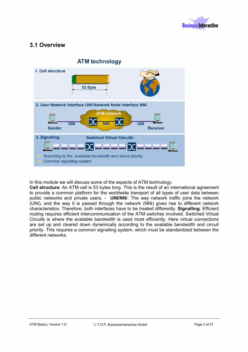
3.1 Overview
In this module we will discuss some of the aspects of ATM technology. Cell structure: An ATM cell is 53 bytes long. This is the result of an international agreement to provide a common platform for the worldwide transport of all types of user data between public networks and private users. - UNI/NNI: The way network traffic joins the network (UNI), and the way it is passed through the network (NNI) gives rise to different network characteristics. Therefore, both interfaces have to be treated differently. Signalling: Efficient routing requires efficient intercommunication of the ATM switches involved. Switched Virtual Circuits is where the available bandwidth is used most efficiently. Here virtual connections are set up and cleared down dynamically according to the available bandwidth and circuit priority. This requires a common signalling system, which must be standardized between the different networks.
ATM Basics, Version 1.6
T.O.P. BusinessInteractive GmbH
Page 4 of 21
3.2 ATM Cell Structure
The ATM cell is 53 bytes long. It consists of a 5 byte header and a 48 byte payload section.The header includes fields containing address and control information, to identify cells belonging to the same virtual circuit, and to notify the ATM switches as to how the different cells are to be handled. This cell is used for both the User-to-Network interface (UNI) and the Network-to-Network interface (NNI). The cell headers used at the UNI are only slightly different from those at the NNI. The UNI specification defines how an end system is connected to an ATM network. It specifies a number of physical interface standards, which in turn define how frames and other data streams are mapped into cells, and how point-to-point connections are set-up across the network. Basically, the NNI doesn't have to look at AALs. But here too, standards are required to guarantee cell switching, routing and interswitch communication.
ATM Basics, Version 1.6
T.O.P. BusinessInteractive GmbH
Page 5 of 21
3.3 ATM Interfaces (1/2)
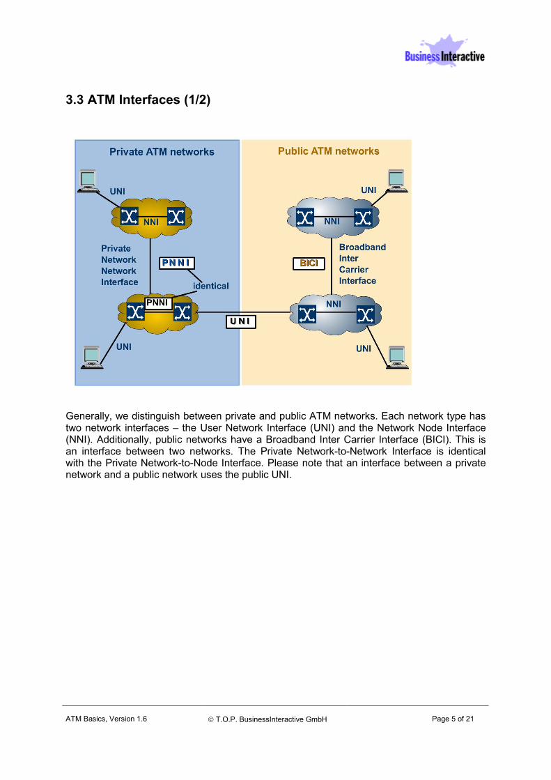
Generally, we distinguish between private and public ATM networks. Each network type has two network interfaces – the User Network Interface (UNI) and the Network Node Interface (NNI). Additionally, public networks have a Broadband Inter Carrier Interface (BICI). This is an interface between two networks. The Private Network-to-Network Interface is identical with the Private Network-to-Node Interface. Please note that an interface between a private network and a public network uses the public UNI.
ATM Basics, Version 1.6
T.O.P. BusinessInteractive GmbH
Page 6 of 21
3.3 ATM Interfaces (2/2)
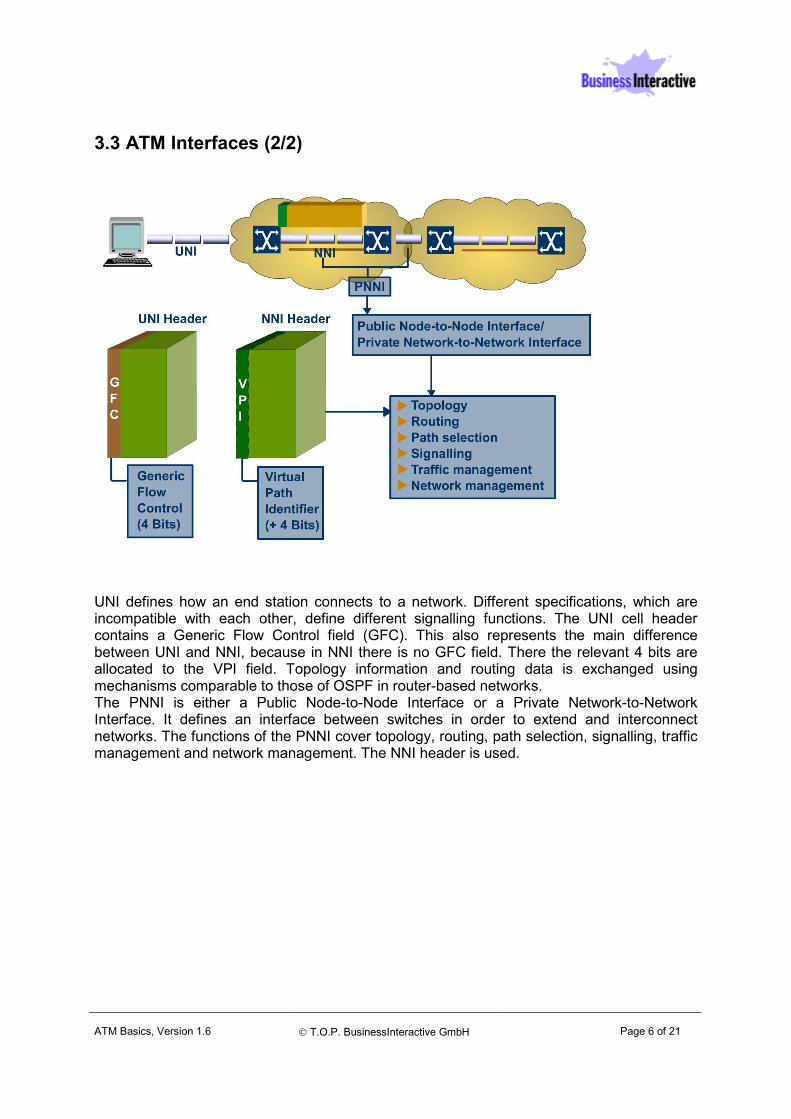
UNI defines how an end station connects to a network. Different specifications, which are incompatible with each other, define different signalling functions. The UNI cell header contains a Generic Flow Control field (GFC). This also represents the main difference between UNI and NNI, because in NNI there is no GFC field. There the relevant 4 bits are allocated to the VPI field. Topology information and routing data is exchanged using mechanisms comparable to those of OSPF in router-based networks. The PNNI is either a Public Node-to-Node Interface or a Private Network-to-Network Interface. It defines an interface between switches in order to extend and interconnect networks. The functions of the PNNI cover topology, routing, path selection, signalling, traffic management and network management. The NNI header is used.

ATM Basics, Version 1.6
T.O.P. BusinessInteractive GmbH
Page 7 of 21
3.3.1 ATM Cell Header Fields (1/3)
The Virtual Channel Identifier, or VCI, field identifies a virtual circuit established between two ATM end stations and any switches in between. The VCI is assigned when a virtual connection has been set up through the ATM signalling process. The end stations and switches use the VCI to route cells over the virtual circuit. The Virtual Path Identifier, or VPI, field is used to identify a group of virtual channels. In a UNI cell this field is 8 bits long. In an NNI cell it is 12 bits long. For virtual connections and paths, the maintenance of the quality of service is of particular importance. The ATM network reserves a specific bandwidth for each virtual circuit. This guarantees the feasibility of real-time applications like voice and video.
ATM Basics, Version 1.6
T.O.P. BusinessInteractive GmbH
Page 8 of 21
3.3.1 ATM Cell Header Fields (2/3)
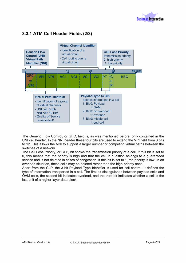
The Generic Flow Control, or GFC, field is, as was mentioned before, only contained in the UNI cell header. In the NNI header these four bits are used to extend the VPI field from 8 bits to 12. This allows the NNI to support a larger number of competing virtual paths between the switches of a network. The Cell Loss Priority, or CLP, bit shows the transmission priority of a cell. If this bit is set to 0, this means that the priority is high and that the cell in question belongs to a guaranteed service and is not deleted in cases of congestion. If this bit is set to 1, the priority is low. In an overload situation, these cells may be deleted rather than the high-priority ones. Apart from the CLP, the 3 bit Payload Type Identifier is used for cell control. It defines the type of information transported in a cell. The first bit distinguishes between payload cells and OAM cells, the second bit indicates overload, and the third bit indicates whether a cell is the last unit of a higher-layer data block.
ATM Basics, Version 1.6
T.O.P. BusinessInteractive GmbH
Page 9 of 21
3.3.1 ATM Cell Header Fields (3/3)
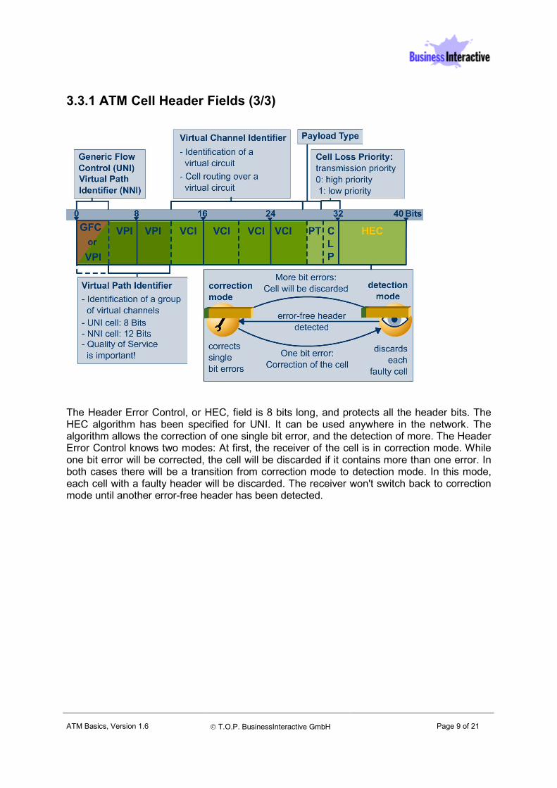
The Header Error Control, or HEC, field is 8 bits long, and protects all the header bits. The HEC algorithm has been specified for UNI. It can be used anywhere in the network. The algorithm allows the correction of one single bit error, and the detection of more. The Header Error Control knows two modes: At first, the receiver of the cell is in correction mode. While one bit error will be corrected, the cell will be discarded if it contains more than one error. In both cases there will be a transition from correction mode to detection mode. In this mode, each cell with a faulty header will be discarded. The receiver won't switch back to correction mode until another error-free header has been detected.
ATM Basics, Version 1.6
T.O.P. BusinessInteractive GmbH
Page 10 of 21
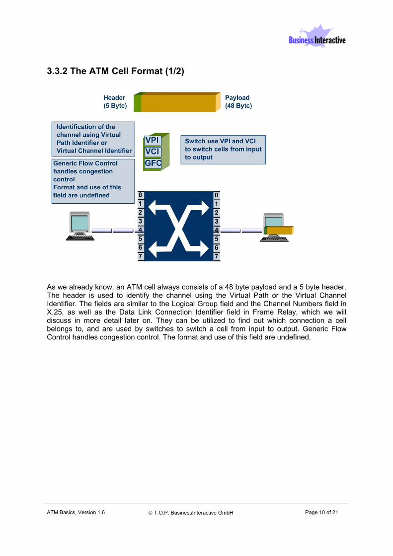
3.3.2 The ATM Cell Format (1/2)
As we already know, an ATM cell always consists of a 48 byte payload and a 5 byte header. The header is used to identify the channel using the Virtual Path or the Virtual Channel Identifier. The fields are similar to the Logical Group field and the Channel Numbers field in X.25, as well as the Data Link Connection Identifier field in Frame Relay, which we will discuss in more detail later on. They can be utilized to find out which connection a cell belongs to, and are used by switches to switch a cell from input to output. Generic Flow Control handles congestion control. The format and use of this field are undefined.
ATM Basics, Version 1.6
T.O.P. BusinessInteractive GmbH
Page 11 of 21
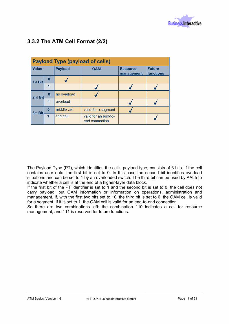
3.3.2 The ATM Cell Format (2/2)
The Payload Type (PT), which identifies the cell's payload type, consists of 3 bits. If the cell contains user data, the first bit is set to 0. In this case the second bit identifies overload situations and can be set to 1 by an overloaded switch. The third bit can be used by AAL5 to indicate whether a cell is at the end of a higher-layer data block. If the first bit of the PT identifier is set to 1 and the second bit is set to 0, the cell does not carry payload, but OAM information or information on operations, administration and management. If, with the first two bits set to 10, the third bit is set to 0, the OAM cell is valid for a segment. If it is set to 1, the OAM cell is valid for an end-to-end connection. So there are two combinations left: the combination 110 indicates a cell for resource management, and 111 is reserved for future functions.
ATM Basics, Version 1.6
T.O.P. BusinessInteractive GmbH
Page 12 of 21
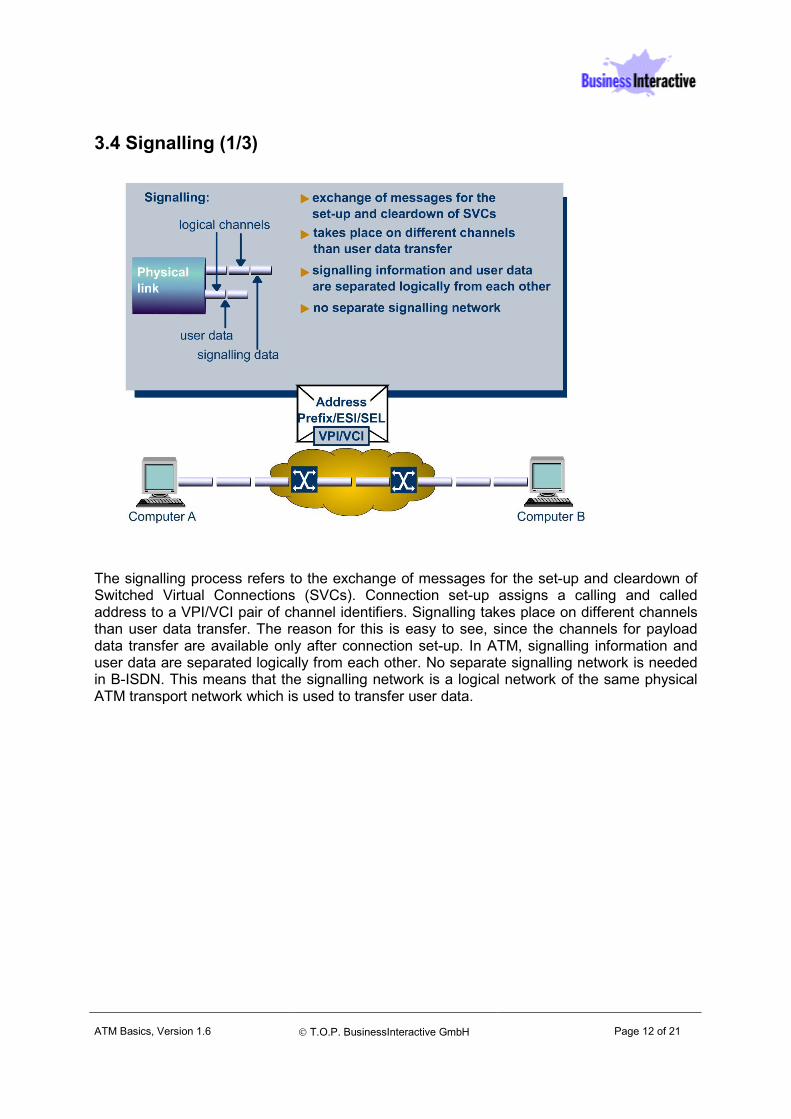
3.4 Signalling (1/3)
The signalling process refers to the exchange of messages for the set-up and cleardown of Switched Virtual Connections (SVCs). Connection set-up assigns a calling and called address to a VPI/VCI pair of channel identifiers. Signalling takes place on different channels than user data transfer. The reason for this is easy to see, since the channels for payload data transfer are available only after connection set-up. In ATM, signalling information and user data are separated logically from each other. No separate signalling network is needed in B-ISDN. This means that the signalling network is a logical network of the same physical ATM transport network which is used to transfer user data.
ATM Basics, Version 1.6
T.O.P. BusinessInteractive GmbH
Page 13 of 21
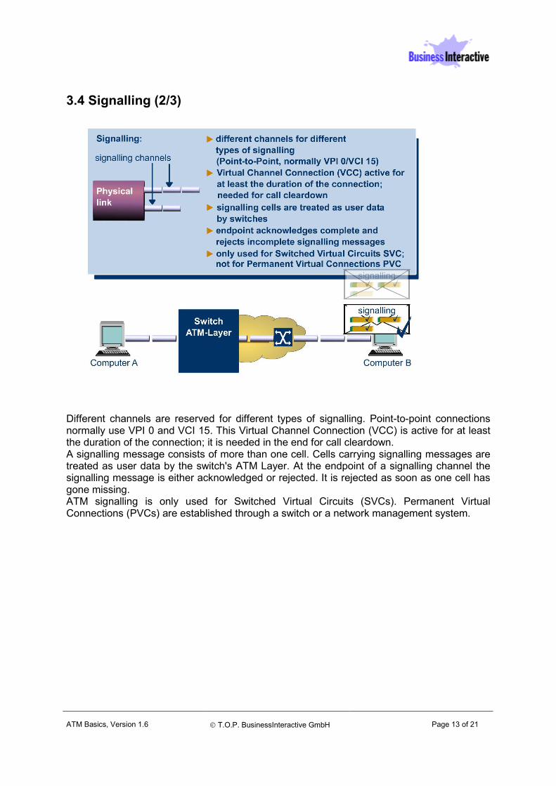
3.4 Signalling (2/3)
Different channels are reserved for different types of signalling. Point-to-point connections normally use VPI 0 and VCI 15. This Virtual Channel Connection (VCC) is active for at least the duration of the connection; it is needed in the end for call cleardown. A signalling message consists of more than one cell. Cells carrying signalling messages are treated as user data by the switch's ATM Layer. At the endpoint of a signalling channel the signalling message is either acknowledged or rejected. It is rejected as soon as one cell has gone missing. ATM signalling is only used for Switched Virtual Circuits (SVCs). Permanent Virtual Connections (PVCs) are established through a switch or a network management system.
ATM Basics, Version 1.6
T.O.P. BusinessInteractive GmbH
Page 14 of 21
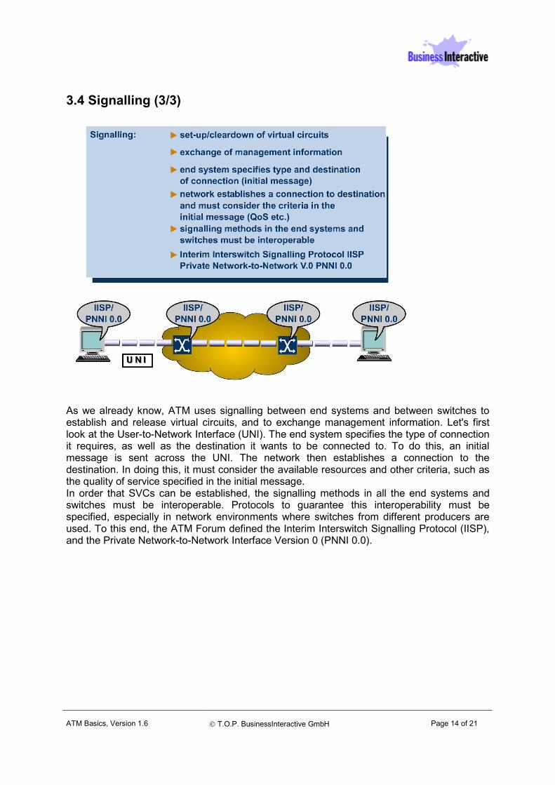
3.4 Signalling (3/3)
As we already know, ATM uses signalling between end systems and between switches to establish and release virtual circuits, and to exchange management information. Let's first look at the User-to-Network Interface (UNI). The end system specifies the type of connection it requires, as well as the destination it wants to be connected to. To do this, an initial message is sent across the UNI. The network then establishes a connection to the destination. In doing this, it must consider the available resources and other criteria, such as the quality of service specified in the initial message. In order that SVCs can be established, the signalling methods in all the end systems and switches must be interoperable. Protocols to guarantee this interoperability must be specified, especially in network environments where switches from different producers are used. To this end, the ATM Forum defined the Interim Interswitch Signalling Protocol (IISP), and the Private Network-to-Network Interface Version 0 (PNNI 0.0).
ATM Basics, Version 1.6
T.O.P. BusinessInteractive GmbH
Page 15 of 21
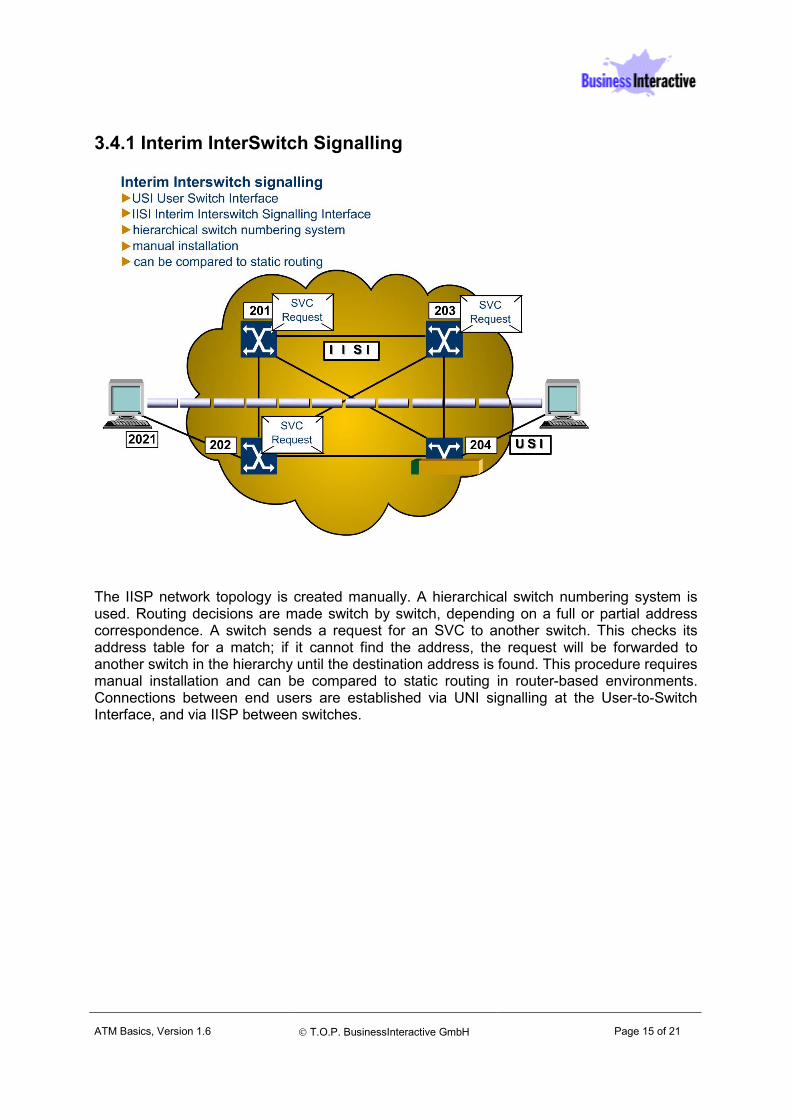
3.4.1 Interim InterSwitch Signalling
The IISP network topology is created manually. A hierarchical switch numbering system is used. Routing decisions are made switch by switch, depending on a full or partial address correspondence. A switch sends a request for an SVC to another switch. This checks its address table for a match; if it cannot find the address, the request will be forwarded to another switch in the hierarchy until the destination address is found. This procedure requires manual installation and can be compared to static routing in router-based environments. Connections between end users are established via UNI signalling at the User-to-Switch Interface, and via IISP between switches.
ATM Basics, Version 1.6
T.O.P. BusinessInteractive GmbH
Page 16 of 21
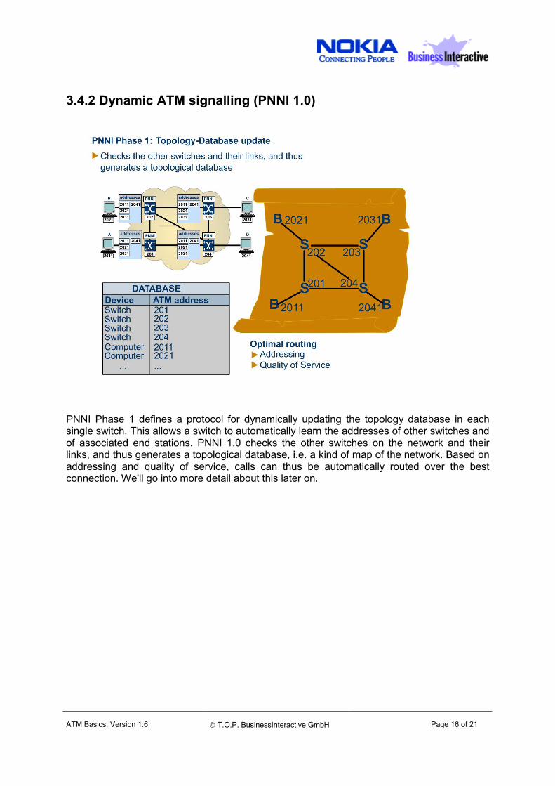
3.4.2 Dynamic ATM signalling (PNNI 1.0)
PNNI Phase 1 defines a protocol for dynamically updating the topology database in each single switch. This allows a switch to automatically learn the addresses of other switches and of associated end stations. PNNI 1.0 checks the other switches on the network and their links, and thus generates a topological database, i.e. a kind of map of the network. Based on addressing and quality of service, calls can thus be automatically routed over the best connection. We'll go into more detail about this later on.
ATM Basics, Version 1.6
T.O.P. BusinessInteractive GmbH
Page 17 of 21
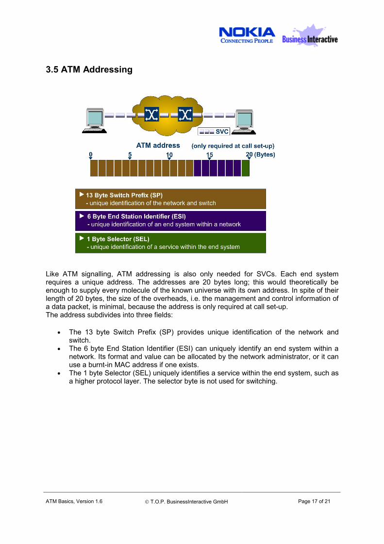
3.5 ATM Addressing
Like ATM signalling, ATM addressing is also only needed for SVCs. Each end system requires a unique address. The addresses are 20 bytes long; this would theoretically be enough to supply every molecule of the known universe with its own address. In spite of their length of 20 bytes, the size of the overheads, i.e. the management and control information of a data packet, is minimal, because the address is only required at call set-up. The address subdivides into three fields:
• The 13 byte Switch Prefix (SP) provides unique identification of the network and switch.
• The 6 byte End Station Identifier (ESI) can uniquely identify an end system within a network. Its format and value can be allocated by the network administrator, or it can use a burnt-in MAC address if one exists.
• The 1 byte Selector (SEL) uniquely identifies a service within the end system, such as a higher protocol layer. The selector byte is not used for switching.
Version 2.0
T.O.P. BusinessInteractive GmbH
Page 18 of 21
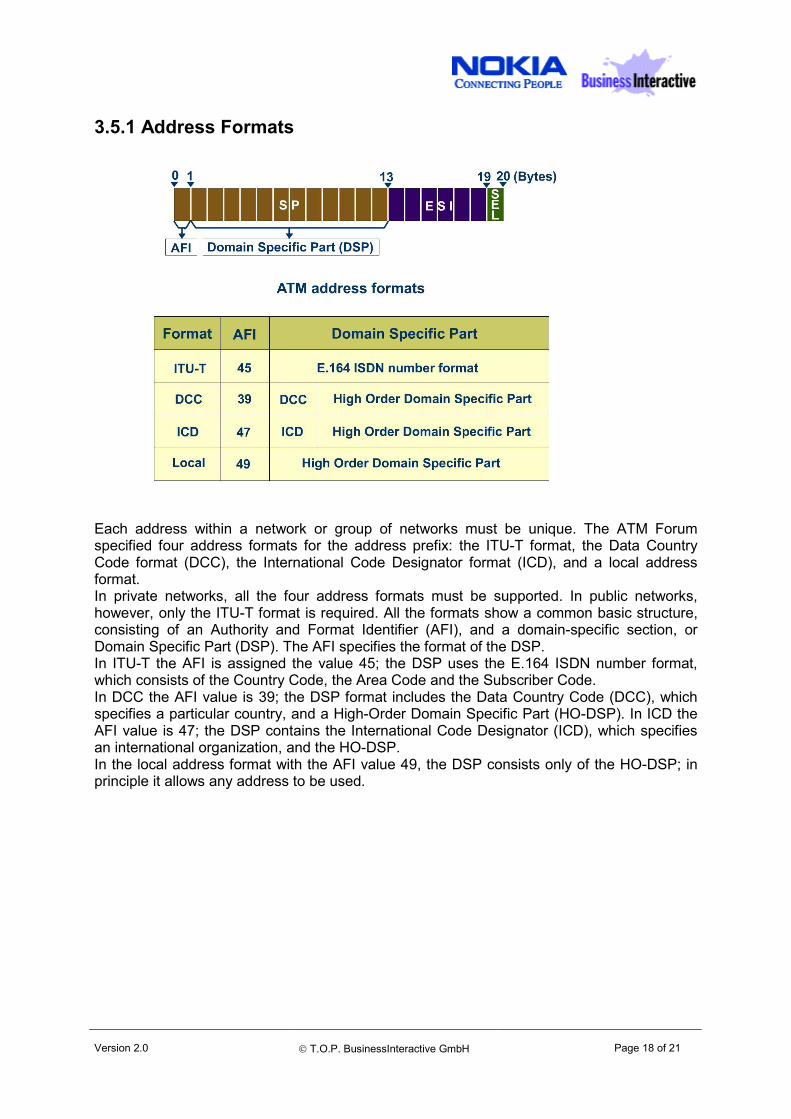
3.5.1 Address Formats
Each address within a network or group of networks must be unique. The ATM Forum specified four address formats for the address prefix: the ITU-T format, the Data Country Code format (DCC), the International Code Designator format (ICD), and a local address format. In private networks, all the four address formats must be supported. In public networks, however, only the ITU-T format is required. All the formats show a common basic structure, consisting of an Authority and Format Identifier (AFI), and a domain-specific section, or Domain Specific Part (DSP). The AFI specifies the format of the DSP. In ITU-T the AFI is assigned the value 45; the DSP uses the E.164 ISDN number format, which consists of the Country Code, the Area Code and the Subscriber Code. In DCC the AFI value is 39; the DSP format includes the Data Country Code (DCC), which specifies a particular country, and a High-Order Domain Specific Part (HO-DSP). In ICD the AFI value is 47; the DSP contains the International Code Designator (ICD), which specifies an international organization, and the HO-DSP. In the local address format with the AFI value 49, the DSP consists only of the HO-DSP; in principle it allows any address to be used.
Version 2.0
T.O.P. BusinessInteractive GmbH
Page 19 of 21
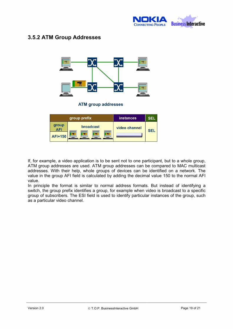
3.5.2 ATM Group Addresses
If, for example, a video application is to be sent not to one participant, but to a whole group, ATM group addresses are used. ATM group addresses can be compared to MAC multicast addresses. With their help, whole groups of devices can be identified on a network. The value in the group AFI field is calculated by adding the decimal value 150 to the normal AFI value. In principle the format is similar to normal address formats. But instead of identifying a switch, the group prefix identifies a group, for example when video is broadcast to a specific group of subscribers. The ESI field is used to identify particular instances of the group, such as a particular video channel.
Version 2.0
T.O.P. BusinessInteractive GmbH
Page 20 of 21
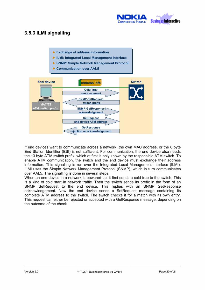
3.5.3 ILMI signalling
If end devices want to communicate across a network, the own MAC address, or the 6 byte End Station Identifier (ESI) is not sufficient. For communication, the end device also needs the 13 byte ATM switch prefix, which at first is only known by the responsible ATM switch. To enable ATM communication, the switch and the end device must exchange their address information. This signalling is run over the Integrated Local Management Interface (ILMI). ILMI uses the Simple Network Management Protocol (SNMP), which in turn communicates over AAL5. The signalling is done in several steps. When an end device in a network is powered up, it first sends a cold trap to the switch. This is a kind of cold start in network traffic. Then the switch sends its prefix in the form of an SNMP SetRequest to the end device. This replies with an SNMP GetResponse acknowledgement. Now the end device sends a SetRequest message containing its complete ATM address to the switch. The switch checks it for a match with its own entry. This request can either be rejected or accepted with a GetResponse message, depending on the outcome of the check.
Version 2.0
T.O.P. BusinessInteractive GmbH
Page 21 of 21
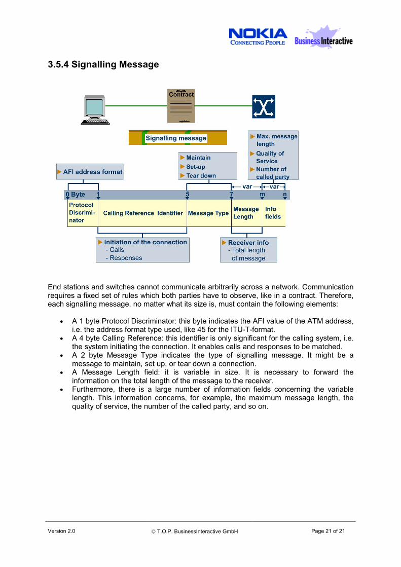
3.5.4 Signalling Message
End stations and switches cannot communicate arbitrarily across a network. Communication requires a fixed set of rules which both parties have to observe, like in a contract. Therefore, each signalling message, no matter what its size is, must contain the following elements:
• A 1 byte Protocol Discriminator: this byte indicates the AFI value of the ATM address, i.e. the address format type used, like 45 for the ITU-T-format.
• A 4 byte Calling Reference: this identifier is only significant for the calling system, i.e. the system initiating the connection. It enables calls and responses to be matched.
• A 2 byte Message Type indicates the type of signalling message. It might be a message to maintain, set up, or tear down a connection.
• A Message Length field: it is variable in size. It is necessary to forward the information on the total length of the message to the receiver.
• Furthermore, there is a large number of information fields concerning the variable length. This information concerns, for example, the maximum message length, the quality of service, the number of the called party, and so on.