atlas copco - simm engineering group · atlas copco’s fd refrigerant dryers. 3 2 5 4 1 6 fd...
TRANSCRIPT
Atlas CopcoRefrigerant Air DryersFD series (6-4000 l/s, 13-8480 cfm)
X
4
1
2
3
5
67
8
9
FD s
erie
s
FD s
erie
s
What is a refrigerant dryer?
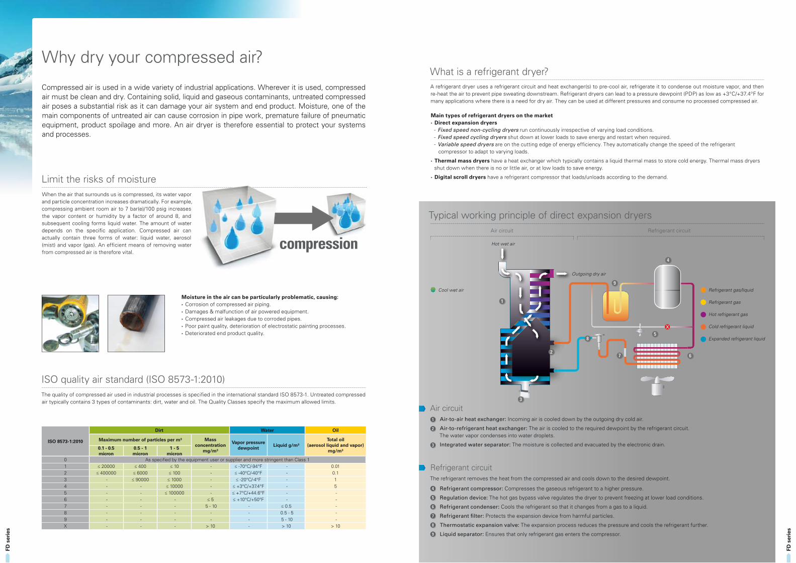
Typical working principle of direct expansion dryers
A refrigerant dryer uses a refrigerant circuit and heat exchanger(s) to pre-cool air, refrigerate it to condense out moisture vapor, and then re-heat the air to prevent pipe sweating downstream. Refrigerant dryers can lead to a pressure dewpoint (PDP) as low as +3°C/+37.4°F for many applications where there is a need for dry air. They can be used at different pressures and consume no processed compressed air.
Main types of refrigerant dryers on the market Direct expansion dryers - Fixed speed non-cycling dryers run continuously irrespective of varying load conditions. - Fixed speed cycling dryers shut down at lower loads to save energy and restart when required. - Variable speed dryers are on the cutting edge of energy efficiency. They automatically change the speed of the refrigerant
compressor to adapt to varying loads.
Thermal mass dryers have a heat exchanger which typically contains a liquid thermal mass to store cold energy. Thermal mass dryers shut down when there is no or little air, or at low loads to save energy.
Digital scroll dryers have a refrigerant compressor that loads/unloads according to the demand.
Air circuit Refrigerant circuit
Refrigerant gas/liquid
Refrigerant gas
Hot refrigerant gas
Cold refrigerant liquid
Expanded refrigerant liquid
Air circuit1 Air-to-air heat exchanger: Incoming air is cooled down by the outgoing dry cold air.
2 Air-to-refrigerant heat exchanger: The air is cooled to the required dewpoint by the refrigerant circuit. The water vapor condenses into water droplets.
3 Integrated water separator: The moisture is collected and evacuated by the electronic drain.
Refrigerant circuit The refrigerant removes the heat from the compressed air and cools down to the desired dewpoint.
4 Refrigerant compressor: Compresses the gaseous refrigerant to a higher pressure.
5 Regulation device: The hot gas bypass valve regulates the dryer to prevent freezing at lower load conditions.
6 Refrigerant condenser: Cools the refrigerant so that it changes from a gas to a liquid.
7 Refrigerant filter: Protects the expansion device from harmful particles.
8 Thermostatic expansion valve: The expansion process reduces the pressure and cools the refrigerant further.
9 Liquid separator: Ensures that only refrigerant gas enters the compressor.
Hot wet air
Cool wet air
Outgoing dry air
Compressed air is used in a wide variety of industrial applications. Wherever it is used, compressed air must be clean and dry. Containing solid, liquid and gaseous contaminants, untreated compressed air poses a substantial risk as it can damage your air system and end product. Moisture, one of the main components of untreated air can cause corrosion in pipe work, premature failure of pneumatic equipment, product spoilage and more. An air dryer is therefore essential to protect your systems and processes.
Limit the risks of moisture
ISO quality air standard (ISO 8573-1:2010)
When the air that surrounds us is compressed, its water vapor and particle concentration increases dramatically. For example, compressing ambient room air to 7 bar(e)/100 psig increases the vapor content or humidity by a factor of around 8, and subsequent cooling forms liquid water. The amount of water depends on the specific application. Compressed air can actually contain three forms of water: liquid water, aerosol (mist) and vapor (gas). An efficient means of removing water from compressed air is therefore vital.
The quality of compressed air used in industrial processes is specified in the international standard ISO 8573-1. Untreated compressed air typically contains 3 types of contaminants: dirt, water and oil. The Quality Classes specify the maximum allowed limits.
Moisture in the air can be particularly problematic, causing: Corrosion of compressed air piping. Damages & malfunction of air powered equipment. Compressed air leakages due to corroded pipes. Poor paint quality, deterioration of electrostatic painting processes. Deteriorated end product quality.
compression
ISO 8573-1:2010
Dirt Water Oil
Maximum number of particles per m³ Mass concentration
mg/m³
Vapor pressure dewpoint
Liquid g/m³Total oil
(aerosol liquid and vapor)mg/m³0.1 - 0.5
micron0.5 - 1 micron
1 - 5 micron
0 As specified by the equipment user or supplier and more stringent than Class 11 ≤ 20000 ≤ 400 ≤ 10 - ≤ -70°C/-94°F - 0.012 ≤ 400000 ≤ 6000 ≤ 100 - ≤ -40°C/-40°F - 0.13 - ≤ 90000 ≤ 1000 - ≤ -20°C/-4°F - 14 - - ≤ 10000 - ≤ +3°C/+37.4°F - 55 - - ≤ 100000 - ≤ +7°C/+44.6°F - - 6 - - - ≤ 5 ≤ +10°C/+50°F - - 7 - - - 5 - 10 - ≤ 0.5 - 8 - - - - - 0.5 - 5 - 9 - - - - - 5 - 10 - X - - - > 10 - > 10 > 10
Why dry your compressed air?
FD s
erie
s
FD s
erie
s
Protecting your reputation and productionCompressed air entering the air net is always 100% saturated. When it cools, this moisture will condense, causing damage to your air system and finished products. Removing moisture from compressed air with a dewpoint as low as +3°C/+37.4°F, Atlas Copco’s FD refrigerant dryers provide the clean, dry air you need to expand the life of your equipment and ensure the quality of your end product. In addition, FD dryers comply with the most stringent environmental regulations.
Keeping your production up and runningAtlas Copco’s FD refrigerant dryers are designed in-house, tested using the most stringent methods (at ambient temperatures up to 50°C/122°F) and manufactured on a very advanced production line. Separate components undergo severe endurance tests while the unique design of the heat exchanger significantly improves the dryer lifetime. Advanced control functions ensure dry air at all conditions and prevent freezing at low loads. FD dryers meet or exceed the international standards for compressed air purity and are tested according to ISO 7183:2007.
Driving down energy costsAtlas Copco’s refrigerant dryers incorporate a range of energy-saving features that will cut your carbon footprint and reduce costs. Incorporating unique heat exchanger technology and Saver Cycle Control, the FD ensures a low pressure drop of typically below 0.2 bar/2.9 psi and minimal energy consumption. The integrated Variable Speed Drive (VSD) technology offers extra energy savings by automatically tuning the energy input to the precise demand. All this ensures a low lifecycle cost.
Easy installation and long maintenance intervalsFD dryers have a small footprint thanks to an innovative all-in-one design. Delivered ready for use, installation is straightforward, minimizing costly production downtime. FD dryers come as all-in-one packages including an electronic no-loss drain, integrated OSD condensate treatment (optional) and spin-on DD/PD filters (optional). For easy installation against the wall, the in- and outlet connections on some models are positioned on top of the unit.
Assuring your peace of mindThrough continuous investment in our competent, committed and efficient service organization, Atlas Copco ensures superior customer value by maximizing productivity. With a presence in over 170 countries, we offer professional and timely service through interaction and involvement. Uptime is ensured by dedicated technicians and 24/7 availability.
Low environmental impact Fully compliant with ISO 14001 standards and Montreal Protocol regulations, FD dryers use CFC-free refrigerants (R134a, R410a, R404a) to prevent any damage to the earth’s ozone layer. FD dryers have an ozone depletion potential (ODP) of zero and are enclosed in a sound suppression canopy to reduce the noise levels, making FD dryers among the most environmentally friendly and quietest in their class.
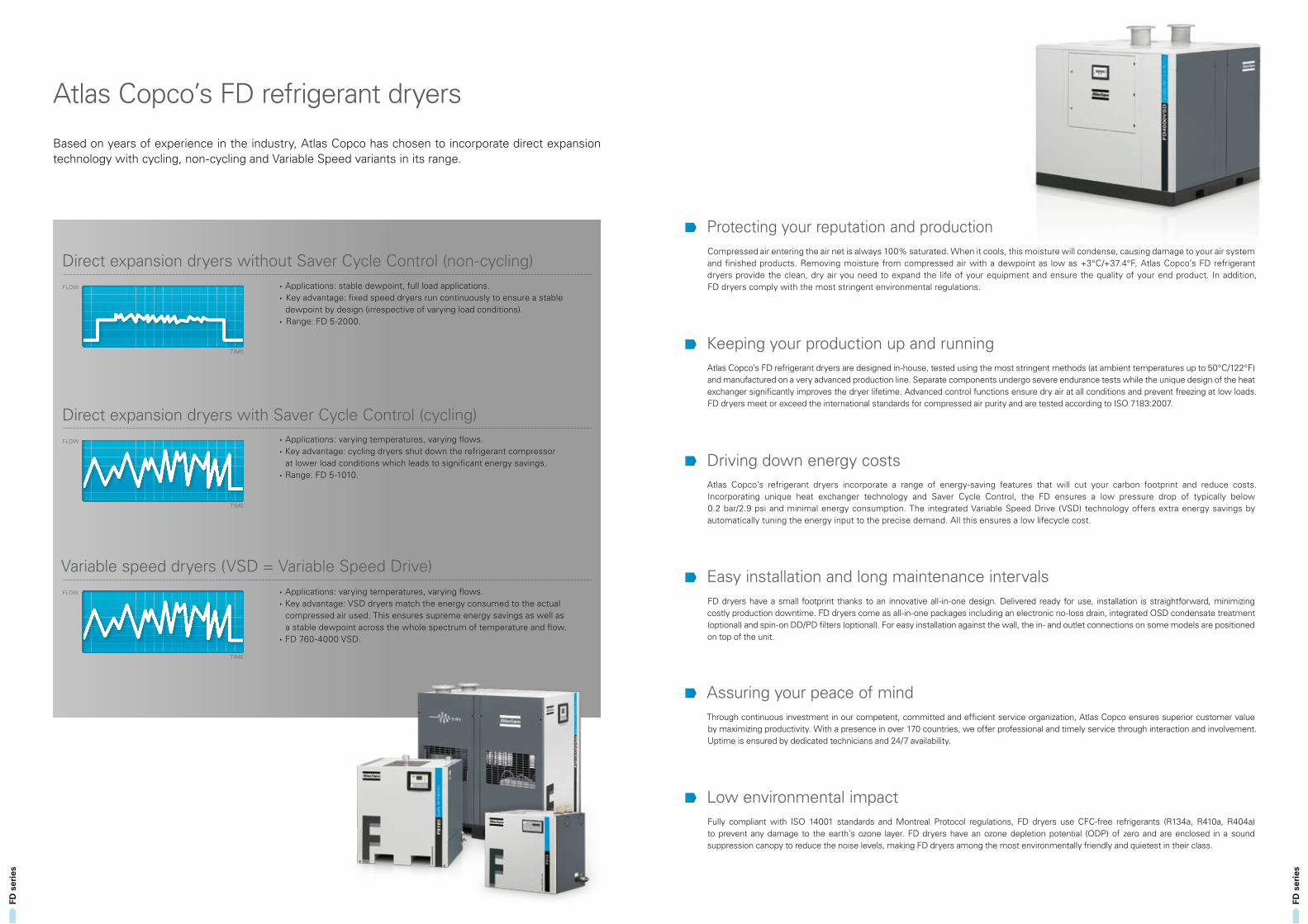
Based on years of experience in the industry, Atlas Copco has chosen to incorporate direct expansion technology with cycling, non-cycling and Variable Speed variants in its range.
Applications: stable dewpoint, full load applications. Key advantage: fixed speed dryers run continuously to ensure a stable
dewpoint by design (irrespective of varying load conditions). Range: FD 5-2000.
Applications: varying temperatures, varying flows. Key advantage: cycling dryers shut down the refrigerant compressor
at lower load conditions which leads to significant energy savings. Range: FD 5-1010.
Applications: varying temperatures, varying flows. Key advantage: VSD dryers match the energy consumed to the actual
compressed air used. This ensures supreme energy savings as well as a stable dewpoint across the whole spectrum of temperature and flow.
FD 760-4000 VSD.
Direct expansion dryers without Saver Cycle Control (non-cycling)
Direct expansion dryers with Saver Cycle Control (cycling)
Variable speed dryers (VSD = Variable Speed Drive)
TIME
FLOW
TIME
FLOW
TIME
FLOW
Atlas Copco’s FD refrigerant dryers
3
2
5
4
1
6
FD s
erie
s
FD s
erie
s
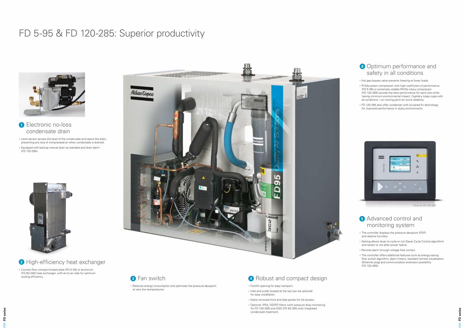
Robust and compact design Forklift opening for easy transport.
Inlet and outlet located at the top (can be optional) for easy installation.
Easily removed front and side panels for full access.
Optional: IP54, DD/PD filters (with pressure drop monitoring for FD 120-285) and OSD (FD 60-285 only) integrated condensate treatment.
High-efficiency heat exchanger Counter-flow compact brazed plate (FD 5-50) or aluminum
(FD 60-285) heat exchanger, with air-to-air side for optimum cooling efficiency.
Optimum performance and safety in all conditions
Hot gas bypass valve prevents freezing at lower loads.
R134a piston compressor with high coefficient of performance (FD 5-95) or extremely reliable R410a rotary compressor (FD 120-285) provide the best performance for each size while having minimum environmental impact. Capillary tubes cope with all conditions – no moving parts for extra reliability.
FD 120-285 also offer condenser with louvered fin technology for improved performance in dusty environments.
Electronic no-loss condensate drain
Level sensor senses the level of the condensate and opens the drain, preventing any loss of compressed air when condensate is drained.
Equipped with backup manual drain as standard and drain alarm (FD 120-285).
Fan switch Reduces energy consumption and optimizes the pressure dewpoint
at very low temperatures.
Advanced control and monitoring system
The controller displays the pressure dewpoint (PDP) and relative humidity.
Setting allows dryer to cycle or not (Saver Cycle Control algorithm) and restart or not after power failure.
Remote alarm through voltage-free contact.
The controller offers additional features such as energy-saving flow switch algorithm, alarm history, standard remote visualization (Ethernet plug) and communication extension possibility (FD 120-285).
* Only for FD 120-285.
FD 5-95 & FD 120-285: Superior productivity
3
2
1
1
2
7
4
5
6
FD s
erie
s
FD s
erie
s
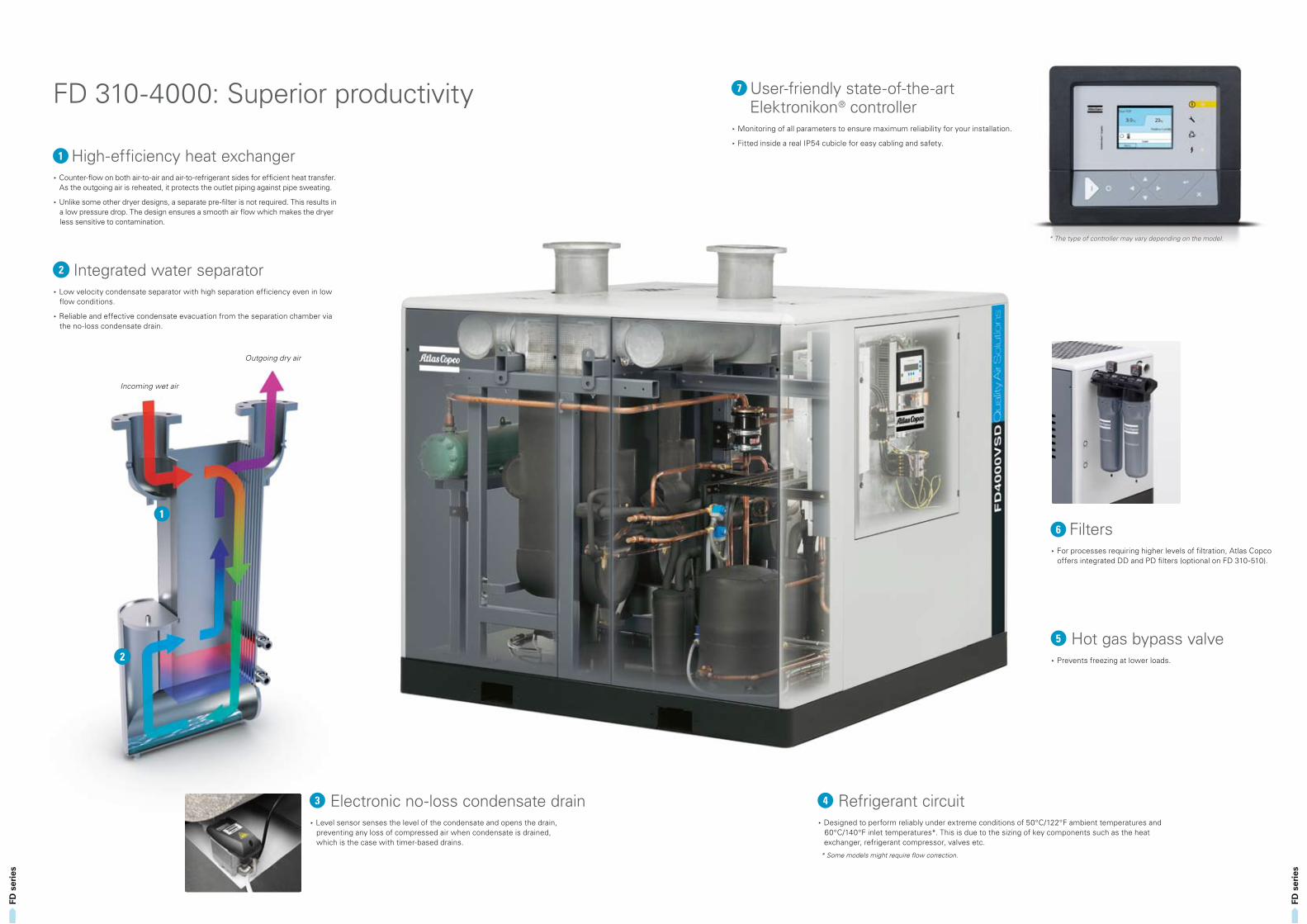
User-friendly state-of-the-art Elektronikon® controller
Monitoring of all parameters to ensure maximum reliability for your installation.
Fitted inside a real IP54 cubicle for easy cabling and safety.
High-efficiency heat exchanger Counter-flow on both air-to-air and air-to-refrigerant sides for efficient heat transfer.
As the outgoing air is reheated, it protects the outlet piping against pipe sweating.
Unlike some other dryer designs, a separate pre-filter is not required. This results in a low pressure drop. The design ensures a smooth air flow which makes the dryer less sensitive to contamination.
Integrated water separator Low velocity condensate separator with high separation efficiency even in low
flow conditions.
Reliable and effective condensate evacuation from the separation chamber via the no-loss condensate drain.
Refrigerant circuit Designed to perform reliably under extreme conditions of 50°C/122°F ambient temperatures and
60°C/140°F inlet temperatures*. This is due to the sizing of key components such as the heat exchanger, refrigerant compressor, valves etc.
* Some models might require flow correction.
Hot gas bypass valve Prevents freezing at lower loads.
Electronic no-loss condensate drain Level sensor senses the level of the condensate and opens the drain,
preventing any loss of compressed air when condensate is drained, which is the case with timer-based drains.
Filters For processes requiring higher levels of filtration, Atlas Copco
offers integrated DD and PD filters (optional on FD 310-510).
Incoming wet air
Outgoing dry air
* The type of controller may vary depending on the model.
FD 310-4000: Superior productivity
FD s
erie
s
FD s
erie
s
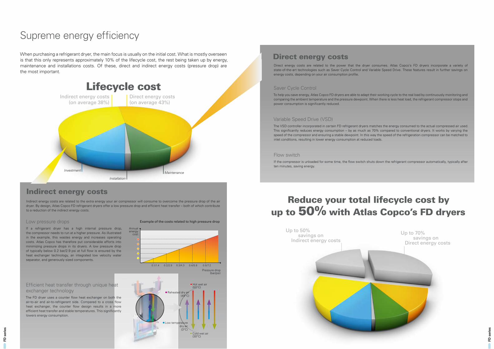
When purchasing a refrigerant dryer, the main focus is usually on the initial cost. What is mostly overseen is that this only represents approximately 10% of the lifecycle cost, the rest being taken up by energy, maintenance and installations costs. Of these, direct and indirect energy costs (pressure drop) are the most important.
Direct energy costs are related to the power that the dryer consumes. Atlas Copco's FD dryers incorporate a variety of state-of-the-art technologies such as Saver Cycle Control and Variable Speed Drive. These features result in further savings on energy costs, depending on your air consumption profile.
Saver Cycle ControlTo help you save energy, Atlas Copco FD dryers are able to adapt their working cycle to the real load by continuously monitoring and comparing the ambient temperature and the pressure dewpoint. When there is less heat load, the refrigerant compressor stops and power consumption is significantly reduced.
Variable Speed Drive (VSD) The VSD controller incorporated in certain FD refrigerant dryers matches the energy consumed to the actual compressed air used. This significantly reduces energy consumption – by as much as 70% compared to conventional dryers. It works by varying the speed of the compressor and ensuring a stable dewpoint. In this way the speed of the refrigeration compressor can be matched to inlet conditions, resulting in lower energy consumption at reduced loads.
Flow switchIf the compressor is unloaded for some time, the flow switch shuts down the refrigerant compressor automatically, typically after ten minutes, saving energy.
Low pressure drops If a refrigerant dryer has a high internal pressure drop, the compressor needs to run at a higher pressure. As illustrated in the example, this wastes energy and increases operating costs. Atlas Copco has therefore put considerable efforts into minimizing pressure drops in its dryers. A low pressure drop of typically below 0.2 bar/2.9 psi at full flow is ensured by the heat exchanger technology, an integrated low velocity water separator, and generously sized components.
Efficient heat transfer through unique heat exchanger technology The FD dryer uses a counter flow heat exchanger on both the air-to-air and air-to-refrigerant side. Compared to a cross flow heat exchanger, the counter flow design results in a more efficient heat transfer and stable temperatures. This significantly lowers energy consumption.
Direct energy costs
Lifecycle cost
Reduce your total lifecycle cost byup to 50% with Atlas Copco’s FD dryers
Example of the costs related to high pressure drop
Annual energy
cost
Pressure drop (bar/psi)
Indirect energy costs are related to the extra energy your air compressor will consume to overcome the pressure drop of the air dryer. By design, Atlas Copco FD refrigerant dryers offer a low pressure drop and efficient heat transfer – both of which contribute to a reduction of the indirect energy costs.
Indirect energy costs
Maintenance Investment
Indirect energy costs (on average 38%)
Direct energy costs (on average 43%)
Installation
Up to 70% savings on Direct energy costs
Up to 50% savings on Indirect energy costs
Hot wet air (50°C)
Cold wet air (30°C)
Reheated dry air (45°C)
Low temperature dry air (3°C)
Supreme energy efficiency
0.1/1.4 0.2/2.9 0.3/4.3 0.4/5.8 0.5/7.2
FD s
erie
s
FD s
erie
s
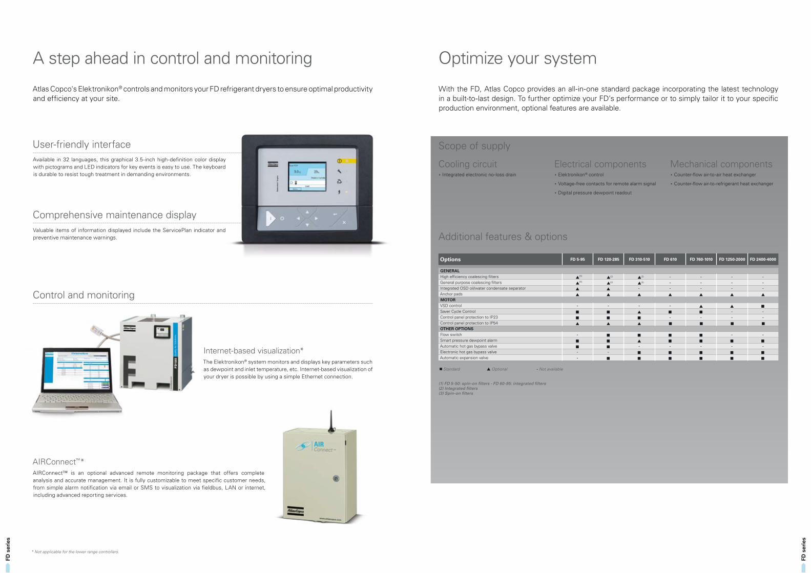
Atlas Copco's Elektronikon® controls and monitors your FD refrigerant dryers to ensure optimal productivity and efficiency at your site.
User-friendly interface
Comprehensive maintenance display
Control and monitoring
Available in 32 languages, this graphical 3.5-inch high-definition color display with pictograms and LED indicators for key events is easy to use. The keyboard is durable to resist tough treatment in demanding environments.
Valuable items of information displayed include the ServicePlan indicator and preventive maintenance warnings.
Internet-based visualization*The Elektronikon® system monitors and displays key parameters such as dewpoint and inlet temperature, etc. Internet-based visualization of your dryer is possible by using a simple Ethernet connection.
AIRConnect™* AIRConnect™ is an optional advanced remote monitoring package that offers complete analysis and accurate management. It is fully customizable to meet specific customer needs, from simple alarm notification via email or SMS to visualization via fieldbus, LAN or internet, including advanced reporting services.
* Not applicable for the lower range controllers.
A step ahead in control and monitoring
With the FD, Atlas Copco provides an all-in-one standard package incorporating the latest technology in a built-to-last design. To further optimize your FD’s performance or to simply tailor it to your specific production environment, optional features are available.
Scope of supply
Additional features & options
Cooling circuit Integrated electronic no-loss drain
Electrical components Elektronikon® control
Voltage-free contacts for remote alarm signal
Digital pressure dewpoint readout
Mechanical components Counter-flow air-to-air heat exchanger
Counter-flow air-to-refrigerant heat exchanger
Options FD 5-95 FD 120-285 FD 310-510 FD 610 FD 760-1010 FD 1250-2000 FD 2400-4000
GENERALHigh efficiency coalescing filters ▲(1) ▲(2) ▲(3) - - - -General purpose coalescing filters ▲(1) ▲(2) ▲(3) - - - -Integrated OSD oil/water condensate separator ▲ ▲ - - - - -Anchor pads ▲ ▲ ▲ ▲ ▲ ▲ ▲
MOTORVSD control - - - - ▲ ▲ ■
Saver Cycle Control ■ ■ ▲ ■ ■ - -Control panel protection to IP23 ■ ■ ■ - - - -Control panel protection to IP54 ▲ ▲ ▲ ■ ■ ■ ■
OTHER OPTIONSFlow switch - ■ ■ ■ ■ - -Smart pressure dewpoint alarm ■ ■ ▲ ■ ■ ■ ■
Automatic hot gas bypass valve ■ ■ - - - - -Electronic hot gas bypass valve - - ■ ■ ■ ■ ■
Automatic expansion valve - ■ ■ ■ ■ ■ ■
■ Standard ▲ Optional - Not available
(1) FD 5-50: spin-on filters - FD 60-95: integrated filters(2) Integrated filters(3) Spin-on filters
Optimize your system
FD s
erie
s
FD s
erie
s
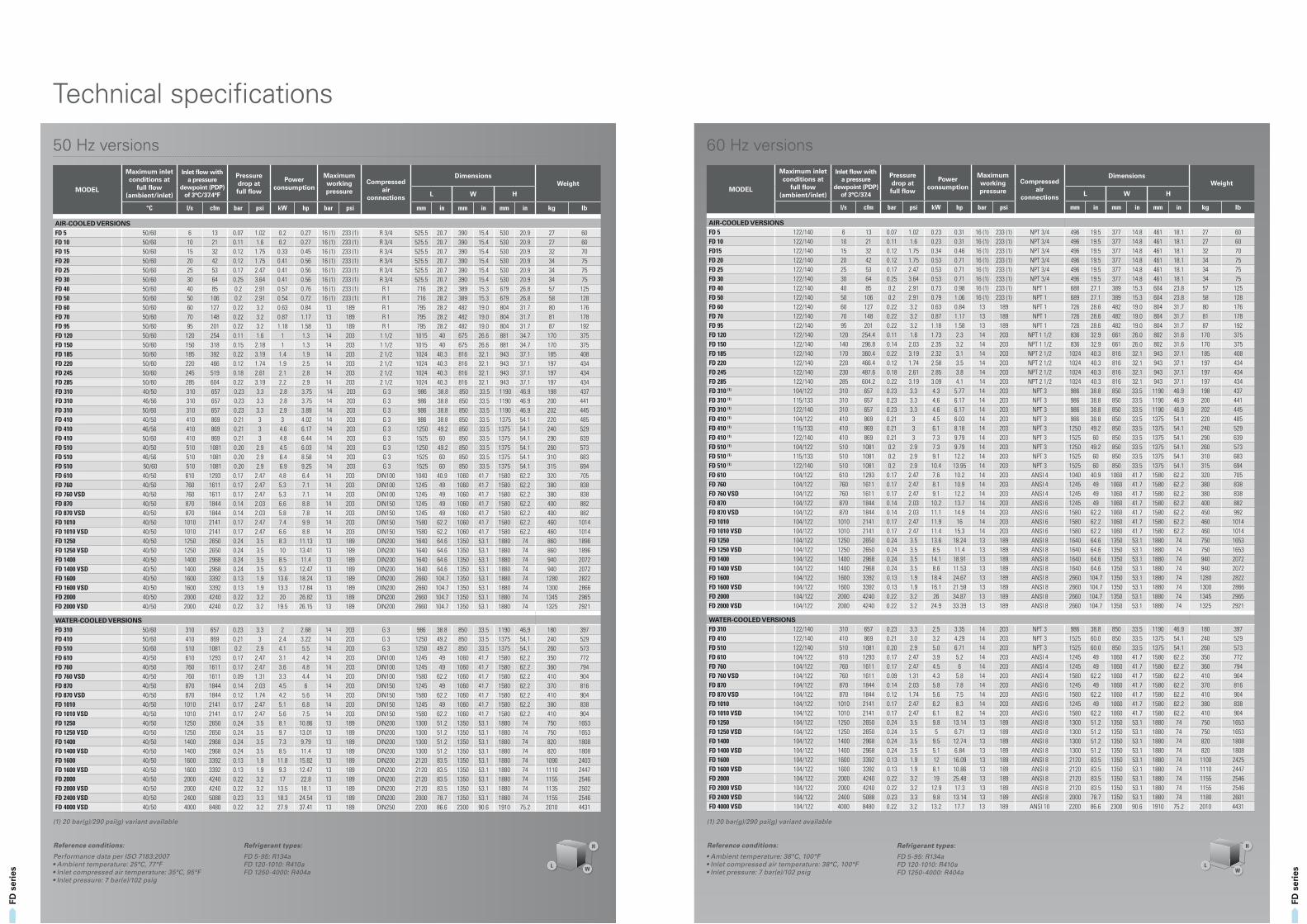
MODEL
Maximum inlet conditions at
full flow (ambient/inlet)
Inlet flow with a pressure
dewpoint (PDP) of 3°C/37.4
Pressure drop at full flow
Power consumption
Maximum working pressure
Compressed air
connections
DimensionsWeight
L W H
l/s cfm bar psi kW hp bar psi mm in mm in mm in kg lb
AIR-COOLED VERSIONS FD 5 122/140 6 13 0.07 1.02 0.23 0.31 16 (1) 233 (1) NPT 3/4 496 19.5 377 14.8 461 18.1 27 60FD 10 122/140 10 21 0.11 1.6 0.23 0.31 16 (1) 233 (1) NPT 3/4 496 19.5 377 14.8 461 18.1 27 60FD15 122/140 15 32 0.12 1.75 0.34 0.46 16 (1) 233 (1) NPT 3/4 496 19.5 377 14.8 461 18.1 32 70FD 20 122/140 20 42 0.12 1.75 0.53 0.71 16 (1) 233 (1) NPT 3/4 496 19.5 377 14.8 461 18.1 34 75FD 25 122/140 25 53 0.17 2.47 0.53 0.71 16 (1) 233 (1) NPT 3/4 496 19.5 377 14.8 461 18.1 34 75FD 30 122/140 30 64 0.25 3.64 0.53 0.71 16 (1) 233 (1) NPT 3/4 496 19.5 377 14.8 461 18.1 34 75FD 40 122/140 40 85 0.2 2.91 0.73 0.98 16 (1) 233 (1) NPT 1 688 27.1 389 15.3 604 23.8 57 125FD 50 122/140 50 106 0.2 2.91 0.79 1.06 16 (1) 233 (1) NPT 1 689 27.1 389 15.3 604 23.8 58 128FD 60 122/140 60 127 0.22 3.2 0.63 0.84 13 189 NPT 1 726 28.6 482 19.0 804 31.7 80 176FD 70 122/140 70 148 0.22 3.2 0.87 1.17 13 189 NPT 1 726 28.6 482 19.0 804 31.7 81 178FD 95 122/140 95 201 0.22 3.2 1.18 1.58 13 189 NPT 1 726 28.6 482 19.0 804 31.7 87 192FD 120 122/140 120 254.4 0.11 1.6 1.73 2.3 14 203 NPT 1 1/2 836 32.9 661 26.0 802 31.6 170 375FD 150 122/140 140 296.8 0.14 2.03 2.35 3.2 14 203 NPT 1 1/2 836 32.9 661 26.0 802 31.6 170 375FD 185 122/140 170 360.4 0.22 3.19 2.32 3.1 14 203 NPT 2 1/2 1024 40.3 816 32.1 943 37.1 185 408FD 220 122/140 220 466.4 0.12 1.74 2.58 3.5 14 203 NPT 2 1/2 1024 40.3 816 32.1 943 37.1 197 434FD 245 122/140 230 487.6 0.18 2.61 2.85 3.8 14 203 NPT 2 1/2 1024 40.3 816 32.1 943 37.1 197 434FD 285 122/140 285 604.2 0.22 3.19 3.09 4.1 14 203 NPT 2 1/2 1024 40.3 816 32.1 943 37.1 197 434FD 310 (1) 104/122 310 657 0.23 3.3 4.3 5.77 14 203 NPT 3 986 38.8 850 33.5 1190 46.9 198 437FD 310 (1) 115/133 310 657 0.23 3.3 4.6 6.17 14 203 NPT 3 986 38.8 850 33.5 1190 46.9 200 441FD 310 (1) 122/140 310 657 0.23 3.3 4.6 6.17 14 203 NPT 3 986 38.8 850 33.5 1190 46.9 202 445FD 410 (1) 104/122 410 869 0.21 3 4.5 6.03 14 203 NPT 3 986 38.8 850 33.5 1375 54.1 220 485FD 410 (1) 115/133 410 869 0.21 3 6.1 8.18 14 203 NPT 3 1250 49.2 850 33.5 1375 54.1 240 529FD 410 (1) 122/140 410 869 0.21 3 7.3 9.79 14 203 NPT 3 1525 60 850 33.5 1375 54.1 290 639FD 510 (1) 104/122 510 1081 0.2 2.9 7.3 9.79 14 203 NPT 3 1250 49.2 850 33.5 1375 54.1 260 573FD 510 (1) 115/133 510 1081 0.2 2.9 9.1 12.2 14 203 NPT 3 1525 60 850 33.5 1375 54.1 310 683FD 510 (1) 122/140 510 1081 0.2 2.9 10.4 13.95 14 203 NPT 3 1525 60 850 33.5 1375 54.1 315 694FD 610 104/122 610 1293 0.17 2.47 7.6 10.2 14 203 ANSI 4 1040 40.9 1060 41.7 1580 62.2 320 705FD 760 104/122 760 1611 0.17 2.47 8.1 10.9 14 203 ANSI 4 1245 49 1060 41.7 1580 62.2 380 838FD 760 VSD 104/122 760 1611 0.17 2.47 9.1 12.2 14 203 ANSI 4 1245 49 1060 41.7 1580 62.2 380 838FD 870 104/122 870 1844 0.14 2.03 10.2 13.7 14 203 ANSI 6 1245 49 1060 41.7 1580 62.2 400 882FD 870 VSD 104/122 870 1844 0.14 2.03 11.1 14.9 14 203 ANSI 6 1580 62.2 1060 41.7 1580 62.2 450 992FD 1010 104/122 1010 2141 0.17 2.47 11.9 16 14 203 ANSI 6 1580 62.2 1060 41.7 1580 62.2 460 1014FD 1010 VSD 104/122 1010 2141 0.17 2.47 11.4 15.3 14 203 ANSI 6 1580 62.2 1060 41.7 1580 62.2 460 1014FD 1250 104/122 1250 2650 0.24 3.5 13.6 18.24 13 189 ANSI 8 1640 64.6 1350 53.1 1880 74 750 1653FD 1250 VSD 104/122 1250 2650 0.24 3.5 8.5 11.4 13 189 ANSI 8 1640 64.6 1350 53.1 1880 74 750 1653FD 1400 104/122 1400 2968 0.24 3.5 14.1 18.91 13 189 ANSI 8 1640 64.6 1350 53.1 1880 74 940 2072FD 1400 VSD 104/122 1400 2968 0.24 3.5 8.6 11.53 13 189 ANSI 8 1640 64.6 1350 53.1 1880 74 940 2072FD 1600 104/122 1600 3392 0.13 1.9 18.4 24.67 13 189 ANSI 8 2660 104.7 1350 53.1 1880 74 1280 2822FD 1600 VSD 104/122 1600 3392 0.13 1.9 16.1 21.59 13 189 ANSI 8 2660 104.7 1350 53.1 1880 74 1300 2866FD 2000 104/122 2000 4240 0.22 3.2 26 34.87 13 189 ANSI 8 2660 104.7 1350 53.1 1880 74 1345 2965FD 2000 VSD 104/122 2000 4240 0.22 3.2 24.9 33.39 13 189 ANSI 8 2660 104.7 1350 53.1 1880 74 1325 2921
WATER-COOLED VERSIONSFD 310 122/140 310 657 0.23 3.3 2.5 3.35 14 203 NPT 3 986 38.8 850 33.5 1190 46.9 180 397FD 410 122/140 410 869 0.21 3.0 3.2 4.29 14 203 NPT 3 1525 60.0 850 33.5 1375 54.1 240 529FD 510 122/140 510 1081 0.20 2.9 5.0 6.71 14 203 NPT 3 1525 60.0 850 33.5 1375 54.1 260 573FD 610 104/122 610 1293 0.17 2.47 3.9 5.2 14 203 ANSI 4 1245 49 1060 41.7 1580 62.2 350 772FD 760 104/122 760 1611 0.17 2.47 4.5 6 14 203 ANSI 4 1245 49 1060 41.7 1580 62.2 360 794FD 760 VSD 104/122 760 1611 0.09 1.31 4.3 5.8 14 203 ANSI 4 1580 62.2 1060 41.7 1580 62.2 410 904FD 870 104/122 870 1844 0.14 2.03 5.8 7.8 14 203 ANSI 6 1245 49 1060 41.7 1580 62.2 370 816FD 870 VSD 104/122 870 1844 0.12 1.74 5.6 7.5 14 203 ANSI 6 1580 62.2 1060 41.7 1580 62.2 410 904FD 1010 104/122 1010 2141 0.17 2.47 6.2 8.3 14 203 ANSI 6 1245 49 1060 41.7 1580 62.2 380 838FD 1010 VSD 104/122 1010 2141 0.17 2.47 6.1 8.2 14 203 ANSI 6 1580 62.2 1060 41.7 1580 62.2 410 904FD 1250 104/122 1250 2650 0.24 3.5 9.8 13.14 13 189 ANSI 8 1300 51.2 1350 53.1 1880 74 750 1653FD 1250 VSD 104/122 1250 2650 0.24 3.5 5 6.71 13 189 ANSI 8 1300 51.2 1350 53.1 1880 74 750 1653FD 1400 104/122 1400 2968 0.24 3.5 9.5 12.74 13 189 ANSI 8 1300 51.2 1350 53.1 1880 74 820 1808FD 1400 VSD 104/122 1400 2968 0.24 3.5 5.1 6.84 13 189 ANSI 8 1300 51.2 1350 53.1 1880 74 820 1808FD 1600 104/122 1600 3392 0.13 1.9 12 16.09 13 189 ANSI 8 2120 83.5 1350 53.1 1880 74 1100 2425FD 1600 VSD 104/122 1600 3392 0.13 1.9 8.1 10.86 13 189 ANSI 8 2120 83.5 1350 53.1 1880 74 1110 2447FD 2000 104/122 2000 4240 0.22 3.2 19 25.48 13 189 ANSI 8 2120 83.5 1350 53.1 1880 74 1155 2546FD 2000 VSD 104/122 2000 4240 0.22 3.2 12.9 17.3 13 189 ANSI 8 2120 83.5 1350 53.1 1880 74 1155 2546FD 2400 VSD 104/122 2400 5088 0.23 3.3 9.8 13.14 13 189 ANSI 8 2000 78.7 1350 53.1 1880 74 1180 2601FD 4000 VSD 104/122 4000 8480 0.22 3.2 13.2 17.7 13 189 ANSI 10 2200 86.6 2300 90.6 1910 75.2 2010 4431
60 Hz versions
LW
HRefrigerant types:
FD 5-95: R134aFD 120-1010: R410aFD 1250-4000: R404a
(1) 20 bar(g)/290 psi(g) variant available
Reference conditions:
• Ambient temperature: 38°C, 100°F• Inlet compressed air temperature: 38°C, 100°F• Inlet pressure: 7 bar(e)/102 psig
MODEL
Maximum inlet conditions at
full flow (ambient/inlet)
Inlet flow with a pressure
dewpoint (PDP) of 3°C/37.4°F
Pressure drop at full flow
Power consumption
Maximum working pressure
Compressed air
connections
DimensionsWeight
L W H
°C l/s cfm bar psi kW hp bar psi mm in mm in mm in kg lb
AIR-COOLED VERSIONS FD 5 50/60 6 13 0.07 1.02 0.2 0.27 16 (1) 233 (1) R 3/4 525.5 20.7 390 15.4 530 20.9 27 60FD 10 50/60 10 21 0.11 1.6 0.2 0.27 16 (1) 233 (1) R 3/4 525.5 20.7 390 15.4 530 20.9 27 60FD 15 50/60 15 32 0.12 1.75 0.33 0.45 16 (1) 233 (1) R 3/4 525.5 20.7 390 15.4 530 20.9 32 70FD 20 50/60 20 42 0.12 1.75 0.41 0.56 16 (1) 233 (1) R 3/4 525.5 20.7 390 15.4 530 20.9 34 75FD 25 50/60 25 53 0.17 2.47 0.41 0.56 16 (1) 233 (1) R 3/4 525.5 20.7 390 15.4 530 20.9 34 75FD 30 50/60 30 64 0.25 3.64 0.41 0.56 16 (1) 233 (1) R 3/4 525.5 20.7 390 15.4 530 20.9 34 75FD 40 50/60 40 85 0.2 2.91 0.57 0.76 16 (1) 233 (1) R 1 716 28.2 389 15.3 679 26.8 57 125FD 50 50/60 50 106 0.2 2.91 0.54 0.72 16 (1) 233 (1) R 1 716 28.2 389 15.3 679 26.8 58 128FD 60 50/60 60 127 0.22 3.2 0.63 0.84 13 189 R 1 795 28.2 482 19.0 804 31.7 80 176FD 70 50/60 70 148 0.22 3.2 0.87 1.17 13 189 R 1 795 28.2 482 19.0 804 31.7 81 178FD 95 50/60 95 201 0.22 3.2 1.18 1.58 13 189 R 1 795 28.2 482 19.0 804 31.7 87 192FD 120 50/60 120 254 0.11 1.6 1 1.3 14 203 1 1/2 1015 40 675 26.6 881 34.7 170 375FD 150 50/60 150 318 0.15 2.18 1 1.3 14 203 1 1/2 1015 40 675 26.6 881 34.7 170 375FD 185 50/60 185 392 0.22 3.19 1.4 1.9 14 203 2 1/2 1024 40.3 816 32.1 943 37.1 185 408FD 220 50/60 220 466 0.12 1.74 1.9 2.5 14 203 2 1/2 1024 40.3 816 32.1 943 37.1 197 434FD 245 50/60 245 519 0.18 2.61 2.1 2.8 14 203 2 1/2 1024 40.3 816 32.1 943 37.1 197 434FD 285 50/60 285 604 0.22 3.19 2.2 2.9 14 203 2 1/2 1024 40.3 816 32.1 943 37.1 197 434FD 310 40/50 310 657 0.23 3.3 2.8 3.75 14 203 G 3 986 38.8 850 33.5 1190 46.9 198 437FD 310 46/56 310 657 0.23 3.3 2.8 3.75 14 203 G 3 986 38.8 850 33.5 1190 46.9 200 441FD 310 50/60 310 657 0.23 3.3 2.9 3.89 14 203 G 3 986 38.8 850 33.5 1190 46.9 202 445FD 410 40/50 410 869 0.21 3 3 4.02 14 203 G 3 986 38.8 850 33.5 1375 54.1 220 485FD 410 46/56 410 869 0.21 3 4.6 6.17 14 203 G 3 1250 49.2 850 33.5 1375 54.1 240 529FD 410 50/60 410 869 0.21 3 4.8 6.44 14 203 G 3 1525 60 850 33.5 1375 54.1 290 639FD 510 40/50 510 1081 0.20 2.9 4.5 6.03 14 203 G 3 1250 49.2 850 33.5 1375 54.1 260 573FD 510 46/56 510 1081 0.20 2.9 6.4 8.58 14 203 G 3 1525 60 850 33.5 1375 54.1 310 683FD 510 50/60 510 1081 0.20 2.9 6.9 9.25 14 203 G 3 1525 60 850 33.5 1375 54.1 315 694FD 610 40/50 610 1293 0.17 2.47 4.8 6.4 14 203 DIN100 1040 40.9 1060 41.7 1580 62.2 320 705FD 760 40/50 760 1611 0.17 2.47 5.3 7.1 14 203 DIN100 1245 49 1060 41.7 1580 62.2 380 838FD 760 VSD 40/50 760 1611 0.17 2.47 5.3 7.1 14 203 DIN100 1245 49 1060 41.7 1580 62.2 380 838FD 870 40/50 870 1844 0.14 2.03 6.6 8.8 14 203 DIN150 1245 49 1060 41.7 1580 62.2 400 882FD 870 VSD 40/50 870 1844 0.14 2.03 5.8 7.8 14 203 DIN150 1245 49 1060 41.7 1580 62.2 400 882FD 1010 40/50 1010 2141 0.17 2.47 7.4 9.9 14 203 DIN150 1580 62.2 1060 41.7 1580 62.2 460 1014FD 1010 VSD 40/50 1010 2141 0.17 2.47 6.6 8.8 14 203 DIN150 1580 62.2 1060 41.7 1580 62.2 460 1014FD 1250 40/50 1250 2650 0.24 3.5 8.3 11.13 13 189 DIN200 1640 64.6 1350 53.1 1880 74 860 1896FD 1250 VSD 40/50 1250 2650 0.24 3.5 10 13.41 13 189 DIN200 1640 64.6 1350 53.1 1880 74 860 1896FD 1400 40/50 1400 2968 0.24 3.5 8.5 11.4 13 189 DIN200 1640 64.6 1350 53.1 1880 74 940 2072FD 1400 VSD 40/50 1400 2968 0.24 3.5 9.3 12.47 13 189 DIN200 1640 64.6 1350 53.1 1880 74 940 2072FD 1600 40/50 1600 3392 0.13 1.9 13.6 18.24 13 189 DIN200 2660 104.7 1350 53.1 1880 74 1280 2822FD 1600 VSD 40/50 1600 3392 0.13 1.9 13.3 17.84 13 189 DIN200 2660 104.7 1350 53.1 1880 74 1300 2866FD 2000 40/50 2000 4240 0.22 3.2 20 26.82 13 189 DIN200 2660 104.7 1350 53.1 1880 74 1345 2965FD 2000 VSD 40/50 2000 4240 0.22 3.2 19.5 26.15 13 189 DIN200 2660 104.7 1350 53.1 1880 74 1325 2921
WATER-COOLED VERSIONSFD 310 50/60 310 657 0.23 3.3 2 2.68 14 203 G 3 986 38.8 850 33.5 1190 46,9 180 397FD 410 50/60 410 869 0.21 3 2.4 3.22 14 203 G 3 1250 49.2 850 33.5 1375 54,1 240 529FD 510 50/60 510 1081 0.2 2.9 4.1 5.5 14 203 G 3 1250 49.2 850 33.5 1375 54,1 260 573FD 610 40/50 610 1293 0.17 2.47 3.1 4.2 14 203 DIN100 1245 49 1060 41.7 1580 62.2 350 772FD 760 40/50 760 1611 0.17 2.47 3.6 4.8 14 203 DIN100 1245 49 1060 41.7 1580 62.2 360 794FD 760 VSD 40/50 760 1611 0.09 1.31 3.3 4.4 14 203 DIN100 1580 62.2 1060 41.7 1580 62.2 410 904FD 870 40/50 870 1844 0.14 2.03 4.5 6 14 203 DIN150 1245 49 1060 41.7 1580 62.2 370 816FD 870 VSD 40/50 870 1844 0.12 1.74 4.2 5.6 14 203 DIN150 1580 62.2 1060 41.7 1580 62.2 410 904FD 1010 40/50 1010 2141 0.17 2.47 5.1 6.8 14 203 DIN150 1245 49 1060 41.7 1580 62.2 380 838FD 1010 VSD 40/50 1010 2141 0.17 2.47 5.6 7.5 14 203 DIN150 1580 62.2 1060 41.7 1580 62.2 410 904FD 1250 40/50 1250 2650 0.24 3.5 8.1 10.86 13 189 DIN200 1300 51.2 1350 53.1 1880 74 750 1653FD 1250 VSD 40/50 1250 2650 0.24 3.5 9.7 13.01 13 189 DIN200 1300 51.2 1350 53.1 1880 74 750 1653FD 1400 40/50 1400 2968 0.24 3.5 7.3 9.79 13 189 DIN200 1300 51.2 1350 53.1 1880 74 820 1808FD 1400 VSD 40/50 1400 2968 0.24 3.5 8.5 11.4 13 189 DIN200 1300 51.2 1350 53.1 1880 74 820 1808FD 1600 40/50 1600 3392 0.13 1.9 11.8 15.82 13 189 DIN200 2120 83.5 1350 53.1 1880 74 1090 2403FD 1600 VSD 40/50 1600 3392 0.13 1.9 9.3 12.47 13 189 DIN200 2120 83.5 1350 53.1 1880 74 1110 2447FD 2000 40/50 2000 4240 0.22 3.2 17 22.8 13 189 DIN200 2120 83.5 1350 53.1 1880 74 1155 2546FD 2000 VSD 40/50 2000 4240 0.22 3.2 13.5 18.1 13 189 DIN200 2120 83.5 1350 53.1 1880 74 1135 2502FD 2400 VSD 40/50 2400 5088 0.23 3.3 18.3 24.54 13 189 DIN200 2000 78.7 1350 53.1 1880 74 1155 2546FD 4000 VSD 40/50 4000 8480 0.22 3.2 27.9 37.41 13 189 DIN250 2200 86.6 2300 90.6 1910 75.2 2010 4431
50 Hz versions
(1) 20 bar(g)/290 psi(g) variant available
Reference conditions:
Performance data per ISO 7183:2007• Ambient temperature: 25°C, 77°F• Inlet compressed air temperature: 35°C, 95°F• Inlet pressure: 7 bar(e)/102 psig
LW
HRefrigerant types:
FD 5-95: R134aFD 120-1010: R410aFD 1250-4000: R404a
Technical specifications
2935
058
2 10
– P
rin
ted
in B
elg
ium
– S
ub
ject
to
alt
erat
ion
wit
ho
ut
pri
or
no
tice
. Nev
er u
se c
om
pre
ssed
air
as
bre
ath
ing
air
wit
ho
ut
pri
or
pu
rifi
cati
on
in a
cco
rdan
ce w
ith
loca
l leg
isla
tio
n a
nd
sta
nd
ard
s.
www.atlascopco.com
Driven by innovation
With more than 135 years of innovation and experience, Atlas Copco will deliver the
products and services to help maximize your company’s efficiency and productivity.
As an industry leader, we are dedicated to offering high air quality at the lowest
possible cost of ownership. Through continuous innovation, we strive to safeguard
your bottom line and bring you peace of mind.
Building on interaction
As part of our long-term relationship with our customers, we have accumulated
extensive knowledge of a wide diversity of processes, needs and objectives. This
gives us the flexibility to adapt and efficiently produce customized compressed air
solutions that meet and exceed your expectations.
A committed business partner
With a presence in over 170 countries, we will deliver high-quality customer
service anywhere, anytime. Our highly skilled technicians are available 24/7
and are supported by an efficient logistics organization, ensuring fast delivery
of genuine spare parts when you need them. We are committed to providing
the best possible know-how and technology to help your company produce,
grow, and succeed. With Atlas Copco you can rest assured that your superior
productivity is our first concern!