atis system t702019
DESCRIPTION
ÂTRANSCRIPT

1
ATIS™ OPERATION MANUAL
Adsorbent Tube Injector System
T702019

2
Introduction The Adsorbent Tube Injector System (ATIS) is a sample preparation device that provides a quick and efficient way to transfer calibrations standards or samples onto an adsorbent tube. The ATIS employs the technique of flash vaporization to vaporize the sample into a continuous flow of an inert gas. The inert gas carries the sample to the tube. After enough time has elapsed, typically less then 5 minutes, the tube is removed from the ATIS and analyzed using the appropriate technique for that adsorbent tube.
The ATIS performs these tasks: • Inject calibration standards onto adsorbent tubes, to calibrate your analytical system. • Inject surrogates and system monitoring compounds onto an adsorbent tube before or after sampling. • Remove moisture from tubes prior to analysis (dry purging). • Vaporize neat compounds into a gas-sampling bag to create a calibration standard.
The ATIS can be expanded: • Thermally extract solid samples and collect the volatiles onto an adsorbent tube. The temperature
range is adjustable from ambient to 120°C. Extraction glassware is available (ordered separately) that will accommodate solid samples up to 76mm (3”) length, and 13mm (1/2”) in diameter.
• Purge volatiles from aqueous samples onto an adsorbent tube at ambient temperatures. A purge &
trap / humidifier module is available (ordered separately) that interfaces with the ATIS. This module can also be used to generate a dynamic humidified stream of an inert gas for spiking calibration standards. The purge & trap module includes purge and trap glassware, and a separate flow controller that allows the user to set a separate purge (wet) flow rate independently of the (dry) flow rate.
How the ATIS Works The ATIS is comprised of the following major components: • Injection Glassware • Adsorbent Injector Heating Block • Carrier Gas Flow Control Injection Glassware The sample pathway of the ATIS is constructed of glass and stainless steel. The calibration standard is injected by a syringe through a replaceable septum in the center of the injection glassware. The injection glassware has an internal volume of 10 milliliters. This provides adequate volume for the vaporized liquid to expand. Injector Heater Block The injector heater block transfers heat produced by the block heater to the injection glassware. The heated glassware vaporizes the sample. A thermometer port is located in the top of the injector block to monitor the temperature during use. Carrier Gas Flow Control A supply of clean gas (nitrogen, helium, or air) is required to flow through the injection glassware during sample introduction. The gas carries the calibration standards / sample to the adsorbent tube during sample preparation. The ATIS includes an adjustable flow controller and an on/off control valve. The flow controller will maintain a constant flow of gas, regardless of changing downstream pressures i.e., an adsorbent tube. The flow range is adjustable from 0 to 110mL/min. This flow controller provides better accuracy and control of the flow rate than a rotameter or needle valve. The on/off valve allows the gas supply to be turned off

3
when the unit is not in use. A gas purifier is included that will remove trace levels of hydrocarbon contaminants from your gas stream. However, additional purification may be required if your gas supply has high contamination levels.
Safety Information The Lab-Line Dri-Bath (Block Heater) included with this product is the heat source for the ATIS. This product operates at temperatures high enough to cause serious burns to the skin. A heat shield is provided to reduce the risk of getting burned while the ATIS is in use. The temperature of the heat shield will be approximately half of the set block temperature. Danger: Do not use the ATIS in the presence of flammable or combustible materials or explosive gases. Fire or explosion may result, causing death or injury. This device contains electrical components that may ignite such materials. Danger: Do not connect the ATIS to any flammable gases i.e., hydrogen. This will create a fire and/or explosion hazard. Warning: The ATIS should be placed in a fume hood or have its own ventilation duct when in use. Warning: Be careful when working around the ATIS when the block heater temperature is turned on. Warning: Do not block the exit port of the pressure relief valve. Doing so could cause pressure to build in the system that may cause the septum to blow out of the septum holder, or worse case, cause the glassware to explode. The pressure relief valve will open to relieve the gas pressure if it exceeds 6psig. Warning: Before performing any maintenance, turn off the block heater, unplug the electrical cord, and allow sufficient time to let the block heater to cool down. In addition to reading this manual, please read the operating manual included with the Lab-Line Dri-Bath (follow the instructions for model 2050) before using the ATIS.
Specifications Dimension Requires a 61mm x 61mm (2’ x 2’) space to house the assembled unit. Power Requirements for the Lab-Line Block Heater Cat# 28520-U ATIS 120 VAC +/-10% 50/60 Hz, 100 Watts, 0.83 Amps Cat# 28521-U ATIS 240 VAC +/-10% 50/60 Hz, 100 Watts, 0.42 Amps Electrical Certifications for the Lab-Line Block Heater
• 110vac model UL-125L Listed • 220vac model CE Marking
Temperature Range with all the ATIS parts attached Slightly above ambient to 120°C (248°F) Pneumatic Specifications Maximum operating pressure 60psig Suggested operating pressure 25-30psig Flow Range 0-110 mL/min at 25-30 psig

4
The ATIS Components • Operation Manual
1. Block Heater 2. 12-Hole Block 3. Injector Heater Block 4. Guide Pins with screws 5. Gas Purifier 6. Copper Tubing 1/8” OD 7. Flow Controller and On/Off Valve & Pressure Relief 8. Polypropylene Tubing 1/8”OD 9. 1/4” to 1/8” Reducing Union 10. Injection Glassware 11. 1/4” Union with Thumbwheel 12. Heat Shield 13. Thermometer 14. Luer / Hose-Barb Adapter
Spare Parts SP1. 6mm Ferrules “Black” SP2. 1/4” Ferrules “Orange” SP3. Half-Hole Septa SP4. Spare Relief Valve and 3/16” Ferrules
12
3
4
5
6
7
8
9 1011 12
13
14SP1
SP2
SP3 SP4

5
Installation
Site Preparation Place the ATIS in a fume hood and away from any combustibles. The ATIS requires a regulated supply (25–30psig) of nitrogen, helium, or air. Nitrogen is your best choice because it is dry, clean, and relatively inexpensive. The ATIS also requires an electrical supply 120 VAC or 240 VAC (depending on the unit you purchased). The Block Heater must be plugged into a grounded outlet. See the operation manual included with Lab-Line Dri-Bath (Block Heater) for additional information.
Tools Required for Assembly (not included) • 3/16” Hex-wrench • Small tubing cutter • Knife or scissors • 7/16” open-end wrench • 1/2” open-end wrench • 9/16” open-end wrench • Flow meter (to set the gas flow rate)
Assembling the ATIS To assemble the ATIS requires you to cut the supplied tubing to fit your workspace, and to attach the tubing to the appropriate fittings. We have installed the appropriate ferrules in each of the fittings for your convenience. The fittings that connect to the ATIS glassware include a Vespel® type ferrule. Use caution when tighten the fittings to the glassware – very little force is needed to create a seal to the glassware. For additional help in plumbing the ATIS see the pneumatic diagram in Appendix 1 of this manual.
The picture to the right illustrates what the ATIS should look like AFTER you have assembled it.
Place the block heater on a flat surface. Place the 12-hole block into the cavity of the block heater with the holes facing up.

6
Install the guide pins to the injector heater block using the hex-head screws provided. Tighten the screws using a 3/16” hex-wrench.
Place the injector heater block (with the open slot facing to your right) in the 12-hole block by aligning the guide pins with the center holes of the 12-hole block.
Using a tubing cutter, cut a piece of copper tubing to connect the gas purifier to a regulated gas supply (user supplied) of nitrogen, helium, or compressed air. Pressure should be set to 25 to 30psig after installation is complete. Using a wrench, tighten the nut 3/4 of a turn, past finger tight.
Cut a second piece of copper tubing to connect the outlet of the gas purifier to the inlet of the on/off valve connected to the flow controller. Using a wrench, tighten both of these nuts 3/4 of a turn, past fingertight. NOTE: Position the flow controller so you have access to it during use.
Open Slot
Danger: Do not plumb the ATIS to any flammable gases i.e., hydrogen. This will create a fire and/or explosion hazard.

7
Connect the 1/4” to 1/8” reducing union to the injection glassware. The SUPELCO Logo on the glassware should face you. Using a wrench, gently tighten the larger nut 1/8 of a turn, past fingertight. NOTE: Over-tightening will cause the glassware to break.
Cut a piece of the white polypropylene tubing to connect the outlet of the flow controller to the union you attached to the Injection Glassware.
Allow extra slack in the tubing so the tubing will absorb the shock if the tubing is accidentally bumped. This helps to prevent the glassware from breaking during use.
Using a wrench, tighten both of these nuts 3/4 of a turn, past fingertight.
Slide the injection glassware into the injector heater block until the stem of the injection glassware protrudes through the recess of the injector block.
Install the thumbwheel to the 1/4” union. See the next section to choose the correct size ferrule to install. Install the 1/4” union over the stem of the glassware that protrudes through the recess. Using a wrench, tighten the CENTER hex portion of the union 1/8 of a turn while holding the injection glassware by the septum holder.
The recess secures the union so you can attach your adsorbent tube by using only the thumbwheel. The recess also promotes heat to transfer to the union. This prevents the calibration standard/sample from condensing inside the union.
Recess
8
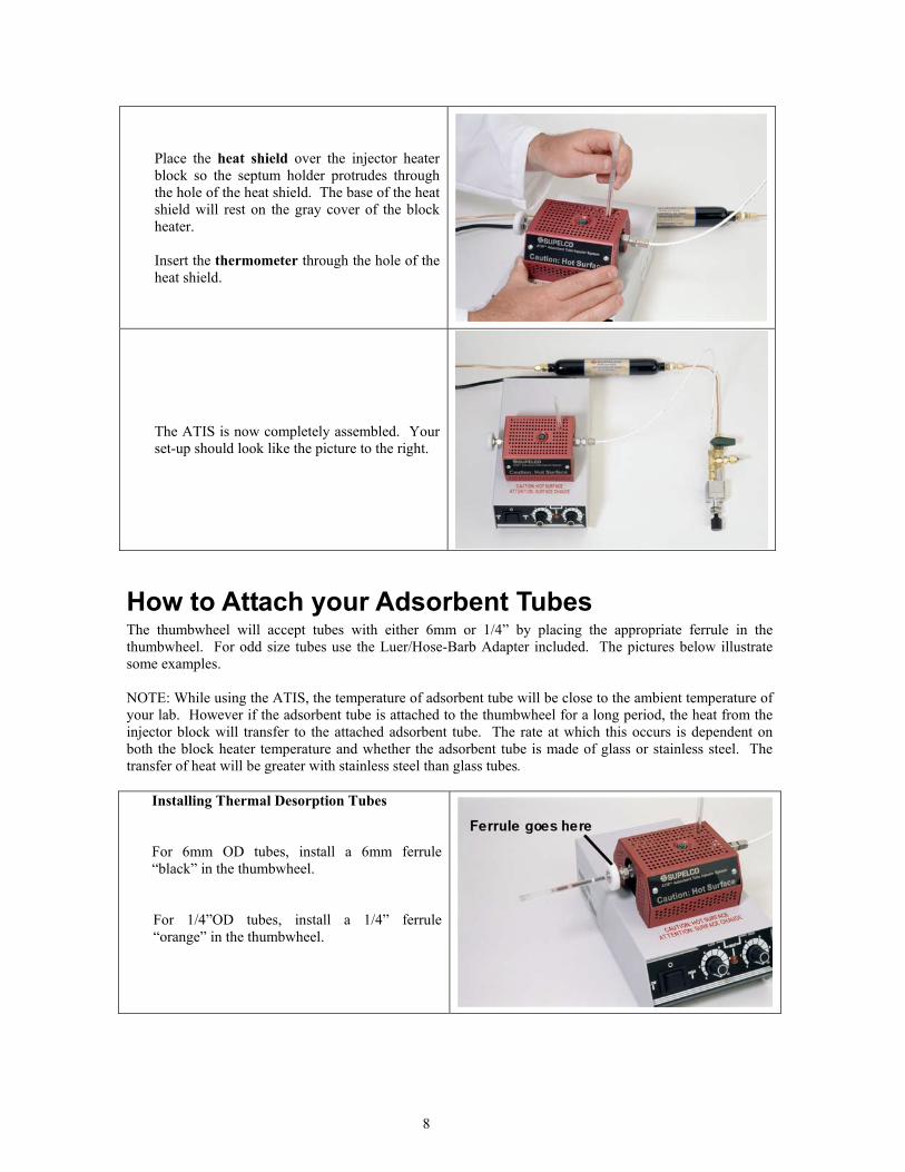
Place the heat shield over the injector heater block so the septum holder protrudes through the hole of the heat shield. The base of the heat shield will rest on the gray cover of the block heater. Insert the thermometer through the hole of the heat shield.
The ATIS is now completely assembled. Your set-up should look like the picture to the right.
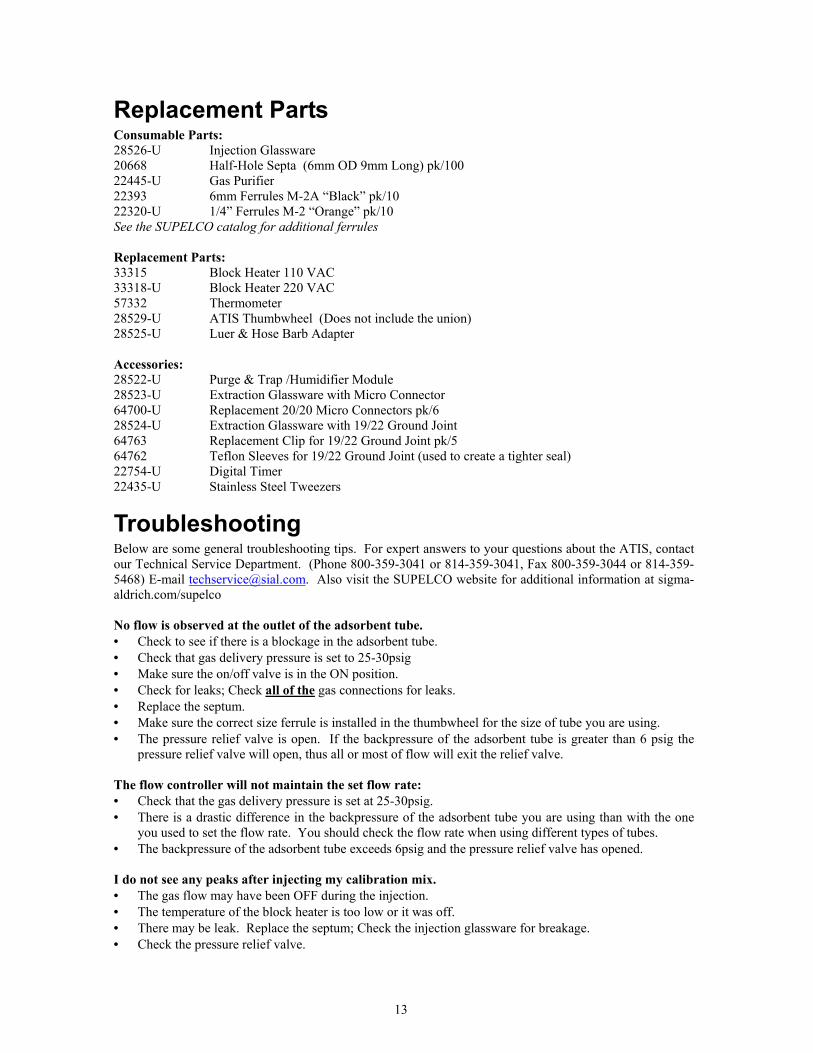
How to Attach your Adsorbent Tubes The thumbwheel will accept tubes with either 6mm or 1/4” by placing the appropriate ferrule in the thumbwheel. For odd size tubes use the Luer/Hose-Barb Adapter included. The pictures below illustrate some examples. NOTE: While using the ATIS, the temperature of adsorbent tube will be close to the ambient temperature of your lab. However if the adsorbent tube is attached to the thumbwheel for a long period, the heat from the injector block will transfer to the attached adsorbent tube. The rate at which this occurs is dependent on both the block heater temperature and whether the adsorbent tube is made of glass or stainless steel. The transfer of heat will be greater with stainless steel than glass tubes.
Installing Thermal Desorption Tubes For 6mm OD tubes, install a 6mm ferrule “black” in the thumbwheel.
For 1/4”OD tubes, install a 1/4” ferrule “orange” in the thumbwheel.

9
Installing Solvent Desorption Tube Use the Luer/Hose-Barb Adapter and a piece of flexible tubing (not supplied) to connect odd size adsorbent tubes. To attach the adapter, install a 1/4” ferrule “orange” in the thumbwheel. The smooth section of the adapter goes into the thumbwheel. Caution: Make sure the flexible tubing you choose will withstand the temperatures you plan on using. The wrong tubing could melt or off-gas by-products if left attached for a long period of time.
Installing Adsorbent Tubes with Male Luer fittings The inner diameter of the Luer/Hose Barb Adapter will accept adsorbent tubes that have a male luer fitting.
Installing Gas-Sampling Bags Gas-sampling bags can be attached using the Luer/Hose-Barb Adapter and a piece of flexible tubing. If the stem of the bag is 3/16” in diameter you can use 3/16” ferrule in the thumbwheel in place of the adapter.
Setting the ATIS Parameters There are two parameters you need set; one is the flow rate, the other is the block temperature.
Setting the Flow Rate (Carrier Gas) Insert the type of adsorbent tube you plan to use in the thumbwheel of the ATIS, and gently tighten the thumbwheel. With the gas supply on, attach a flow meter to the opposite end of the adsorbent tube. Turn the on/off valve attached to the flow controller to the ON position (The arrow on the knob should be pointing towards the flow controller when it is ON). Adjust the gas flow rate using the black knob of the flow controller.
• To increase the flow rate -- turn the knob counter-clockwise. • To decrease the flow rate -- turn the knob clockwise.

10
The flow controller has a 13-turn adjustment knob; each complete turn of the knob is approximately 8 to 10mL/min change in the flow rate. The flow range of the flow controller is 0 to 110mL/min at 25-30psig. Caution: Do not over-tighten the flow controller knob in either direction, or you could damage the flow controller.
Setting the Temperature The power switch is located on the left side of the block heater. When the switch is in the center position, the unit is OFF. Depressing the switch to the left engages the Low Heat range control. Depressing the switch to the right engages the High Heat range control. The temperature range of the block heater with all the ATIS components attached: • Low Heat Range is slightly above ambient to about 60°C (140°F) • High Heat Range is near 50°C to 120°C (122°F to 248°F)
Maintenance Suggested maintenance for the ATIS includes the following: • Check the temperature setting daily. • Check the flow rate daily. • Replace the septum after 25 injections. • Replace the injection glassware after the first sign of any deposits. • Replace the gas purifier annually.
Replacing the Pressure Relief Valve In the event that you need to replace the pressure relief valve, a spare valve is included with the ATIS. To replace the valve: 1) Remove the nut that holds the relief valve.
Note: You may have to break the old relief valve to remove it from the nut. 2) Place a new 3/16” ferrule in the fitting. 3) Start the nut on the threads of the fitting. 4) Insert the relief valve through the nut and into the ferrule. 5) Gently push the relief valve so it is flush with nut. 6) Tighten the nut 1/8 to 1/4 of a turn. Do not over-tighten.
LOW POWER SWITCH HIGH

11
Guidelines for Using the ATIS To accurately quantify the concentration of a sample, taken with an adsorbent tube, the analytical system must first be calibrated. The ATIS simplifies this task. Below are some starting parameters to begin using the ATIS. Some experimentation may be needed to optimize the proper conditions for your application. Allow enough time for the block heater to equilibrate to the desired temperature before injecting your standards. You will also want to make sure you have gas flowing through your adsorbent tube, prior to injecting your standard so the compounds will be carried to the tube.
Injecting Gas Phase Standards Gas phase standards are those typically available in compressed gas cylinders, made up in gas sampling bags, or gas sampling bulbs. • Set the block temperature between 60° to 75°C. • Set the flow rate of the carrier gas to 50mL/min. • Allow the adsorbent tube to remain attached for 2 to 5 minutes after injecting the gas mix with the
carrier gas on. • The delivery rate of the gas syringe should be less than 10mL/min.
Large syringe volumes of gas standards can be injected through the septum of the injection glassware, but the injection rate of the syringe plunger must be slow. The rate that you inject the gas mix will have an effect on the total flow going through the adsorbent tube. For example: If you injected a 100mL syringe volume of a gas mix into the injection glassware, and it took you 10 seconds to inject the entire 100mL volume. The flow rate going through the adsorbent tube for those 10 seconds is 600mL/min. That is too fast. There is a good chance that the compounds in the gas mix could
breakthrough the adsorbent and not be retained. In general, the delivery rate should be less than 10mL/min.
Injecting Liquid Phase Standards Liquid standards are typically made up in a solvent such as: methanol, hexane, or carbon disulfide. • Set the block temperature 10°C above the boiling point of the solvent. • Set the flow rate of the carrier gas to 50mL/min • Allow the tube to remain attached for 2 to 5 minutes after injecting the liquid mix with the carrier gas
flowing through the tube. Note: If compounds in your liquid standard are larger than C12, set the block heater temperature to 100°C Unlike gas standards there is a limit to how much volume you can inject. If too much liquid is injected, the liquid could flashback into the plumbing of the system. Injection volumes of any liquid should be limited to 25 microliters or less. The injection rate for liquid standards can be quicker than that of gas standards, since the displacement of microliter volumes will have minimum impact on the flow rate going through the adsorbent tube. It is important to allow enough time for the contents of the liquid standard to exit the injection glassware before removing the adsorbent tube. For example; If the flow rate of the carrier gas is set to 50mL/min, after two minutes the injection glassware will have been purged 10 times. Ten exchanges are typically enough to completely purge all of the compounds from the injection glassware.

12
Dry Purging When samples are taken in humid atmospheres, the adsorbent tube may retain some moisture. Moisture retention is dependent on the type of adsorbent used. In general, it is best to remove this moisture prior to analyses. The ATIS simplifies this task. Makes sure the injection glassware is clean prior to performing this task. • Set the block temperature to 50°C • Set the flow rate of the carrier gas to 50mL/min. • The total time/volume to leave the adsorbent tube attached will need to be determined experimentally. The key to dry purging is to allow enough (dry) gas to pass through the tube and carry the moisture away. Too much dry purge can actually start to push the compounds of interest through the adsorbent (Breakthrough). Dry purge is usually referenced as a volume instead of time. Dry Purge Volumes for a few types of adsorbents Tenax and Carbotrap(s) adsorbents usually need only 0.25 liters of dry purge (five minutes at 50mL/min). Carbosieve and Carboxen(s) adsorbents may need anywhere from 0.5 liters to 3 liters, depending on how much moisture was in the air during sampling. Gas-Sampling Bags The ATIS can be used to vaporize neat compound(s) prior to injecting them into the bag. Gas sampling bags are often used to make calibration standards. Simply install the gas-sampling bag in the thumbwheel, and the process of filling the bag and injecting the compound can happen at the same time. By volatizing the compounds with the ATIS, it allows you to use the contents of the bag immediately without having to let it equilibrate overnight. Using the Extraction Glassware (ordered separately)
Two different styles of extraction glassware are available, one with a micro connector, the other with a ground joint. The style you choose is your preference; both have their advantages. Both styles include a replaceable septum and glass frit at the outlet. The replaceable septum allows surrogate or internal standards to be injected during the extraction process. The glass frit helps to prevent solids from passing through to the adsorbent tube during the extraction.
Solid samples up to 13mm (1/2”) OD and 76mm (3”) in length can be inserted into both styles. To use the extraction glassware, simply remove the injection glassware from the injector heater block and reinstall the fittings as described in the assembly instruction of injection glassware. See Appendix 2: ATIS Glassware Configurations for additional information.
In most extraction applications, the block temperature is set to the desired temperature, and the sample is placed in the glassware using a probe or tweezers. Caution: Be extremely careful when working with high temperatures. Whether you choose to have the adsorbent tube attached to the thumbwheel before, or after you place the sample in the extraction glassware is up to you. By attaching the adsorbent after the sample is placed in the glassware will allow some of the volatiles to exit before being collected by the tube. In some applications this may be desirable.
This picture illustrates an example of a bud of a flower being placed into the extraction glassware.
13
Replacement Parts Consumable Parts: 28526-U Injection Glassware 20668 Half-Hole Septa (6mm OD 9mm Long) pk/100 22445-U Gas Purifier 22393 6mm Ferrules M-2A “Black” pk/10 22320-U 1/4” Ferrules M-2 “Orange” pk/10 See the SUPELCO catalog for additional ferrules Replacement Parts: 33315 Block Heater 110 VAC 33318-U Block Heater 220 VAC 57332 Thermometer 28529-U ATIS Thumbwheel (Does not include the union) 28525-U Luer & Hose Barb Adapter Accessories: 28522-U Purge & Trap /Humidifier Module 28523-U Extraction Glassware with Micro Connector 64700-U Replacement 20/20 Micro Connectors pk/6 28524-U Extraction Glassware with 19/22 Ground Joint 64763 Replacement Clip for 19/22 Ground Joint pk/5 64762 Teflon Sleeves for 19/22 Ground Joint (used to create a tighter seal) 22754-U Digital Timer 22435-U Stainless Steel Tweezers
Troubleshooting Below are some general troubleshooting tips. For expert answers to your questions about the ATIS, contact our Technical Service Department. (Phone 800-359-3041 or 814-359-3041, Fax 800-359-3044 or 814-359-5468) E-mail [email protected]. Also visit the SUPELCO website for additional information at sigma-aldrich.com/supelco No flow is observed at the outlet of the adsorbent tube. • Check to see if there is a blockage in the adsorbent tube. • Check that gas delivery pressure is set to 25-30psig • Make sure the on/off valve is in the ON position. • Check for leaks; Check all of the gas connections for leaks. • Replace the septum. • Make sure the correct size ferrule is installed in the thumbwheel for the size of tube you are using. • The pressure relief valve is open. If the backpressure of the adsorbent tube is greater than 6 psig the
pressure relief valve will open, thus all or most of flow will exit the relief valve. The flow controller will not maintain the set flow rate: • Check that the gas delivery pressure is set at 25-30psig. • There is a drastic difference in the backpressure of the adsorbent tube you are using than with the one
you used to set the flow rate. You should check the flow rate when using different types of tubes. • The backpressure of the adsorbent tube exceeds 6psig and the pressure relief valve has opened. I do not see any peaks after injecting my calibration mix. • The gas flow may have been OFF during the injection. • The temperature of the block heater is too low or it was off. • There may be leak. Replace the septum; Check the injection glassware for breakage. • Check the pressure relief valve.
14
I am seeing extraneous peaks in my analyses. • Check the glassware, it may be contaminated. • Gas purifier may need to be changed. • May need to install additional gas purification. • The calibration standard or sample may have flashed back into the pneumatics of the ATIS. This may
require you to purchase a new flow controller, on/off valve, and to replace the tubing. Contact our Technical Service for assistance in ordering replacement parts.
Questions & Answers Q: Can I leave the unit turned ON for an extended period?
A: Yes, leaving the temperature of the block heater on, and a flow of gas going through the injection glassware will help to keep the glassware clean and ready for use. To save electrical energy: Utilized the feature of the two temperature ranges of the block heater: Set the low range temperature to around 50°C, and use the high range setting for the temperature you are using to inject your standards. When you are not using the ATIS for an extended period of time, just simply set the power switch to the low range.
Q: Can I use Teflon ferrules instead of the VESPEL ferrules to connect the ATIS glassware?
A: Yes, You can use Teflon ferrules instead of VESPEL ferrules. The VESPEL ferrules were chosen for their inert properties and high reusability. All of the ATIS glassware uses 1/4” OD connections.
Q: How can I be sure that I have complete transfer of my calibration standard?
A: This may require you to do some experimentation by making several analytical runs of your spiked adsorbent tubes. Change the amount of time you leave the tube attached after making an injection from 2 to 5 minutes. Also, experiment by raising the temperature of the injection block. Compare the results. In most cases you will not need to change the flow rate from 50mL/min
Q: How can I determine if my adsorbent tube is dry? (Dry Purge)
A: The best way is to weigh the adsorbent tube and record its tare weight prior to sampling. Then after sampling, reweigh the tube. If the difference is greater than 2 milligrams you may want to remove the moisture prior to analysis. Attach the tube to the ATIS and allow 0.5 to 1 Liter of the carrier gas to pass through the tube. Reweigh the tube. The adsorbent tube can be considered dry when it is within 1.0mg of the weight of the tube prior to sampling.
Q: Why does the pressure relief valve open at 6psig?
A: The pressure relief valve is designed to relieve the pressure if an adsorbent tube with a complete blockage was accidentally installed. The relief valve prevents pressure from building up in ATIS glassware. The pressure relief valve will reseal itself, once the pressure falls below 6psig.
Q: Does the white polypropylene tubing off-gas volatiles?
A: No, this tubing does not off-gas any volatiles at ambient temperatures. However if the tubing is heated, some volatiles should be expected. The maximum temperature of this tubing is 93°C (200°F).
Trademarks: ATIS – Sigma-Aldrich Carbotrap– Sigma-Aldrich Carboxen– Sigma-Aldrich Teflon, VESPEL - E.I du Pont de Nemours & Co., Inc. Tenax- Enka Research Institute Arhem Lab-Line Dri-bath- Barnstead International
15
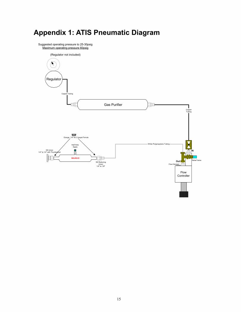
Appendix 1: ATIS Pneumatic Diagram
Copper Tubing
CopperTubing
White Polypropylene Tubing
Flow Element
FlowController
IN
Out
Gas Purifier
Orange 1/4" M-2 Vespel Ferrule
Suggested operating pressure to 25-30psigMaximum operating pressure 60psig
(Regulator not included)
Half-HoleSepta
SS ReducingUnion
1/4" to 1/8"
Regulator
SS Union1/4" to 1/4" with Thumbwheel
Relief Valve

16
Appendix 2: ATIS Glassware Configurations
White PolypropyleneTubing
White PolypropyleneTubing
White PolypropyleneTubing
SS Reducing Union1/4" to 1/8"
SS ReducingUnion
1/4" to 1/8"
SS ReducingUnion
1/4" to 1/8"
3
2
1
Orange 1/4" M-2 Vespel Ferrule
SS Union1/4" to 1/4" with Thumbwheel
SS Union1/4" to 1/4" with Thumbwheel
SS Union1/4" to 1/4" with Thumbwheel
1. Standard Injection Glassware Cat# 28526-U2. Extraction Glassware with Ground Joint Cat# 28524-U3. Extraction Glassware with Micro Connector Cat# 28523-U
Orange 1/4" M-2 Vespel Ferrule
Orange 1/4" M-2 Vespel Ferrule

© 2002 Sigma-Aldrich Co. Printed in USA. Supelco brand products are sold through Sigma-Aldrich, Inc. Sigma-Aldrich, Inc. warrants that its products conform to the information containedin this and other Sigma-Aldrich publications. Purchaser must determine the suitability of the product(s) for their particular use. Additional terms and conditions may apply. Please see reverseside of the invoice or packing slip.
The SIGMA-ALDRICH FamilyWe are committed to the success of our Customers, Employees and Shareholders through leadership in Life Science, High Technology and Service.
Order/Customer Service 800-247-6628, 800-325-3010 ● Fax 800-325-5052 ● E-mail [email protected]
Technical Service 800-359-3041, 814-359-3041 ● Fax 800-359-3044, 814-359-5468 ● E-mail [email protected]
SUPELCO � Supelco Park, 595 North Harrison Road, Bellefonte, PA 16823-0048 � 814-359-3441
sigma-aldrich.com/supelco
T702019