atex table of contents - hoisting...
TRANSCRIPT

426
ATEX Table of contents
Page General information 428 - 441
ATEX Pneumatic chain hoists 442 - 447
ATEX Hand chain hoists 448 - 459
ATEX Trolleys 460 - 462
ATEX Ratchet lever hoist 463
ATEX Electric winch & Accessories 464 - 465
ATEX Manual winch 466
ATEX Rack & Pinion jack 467
ATEX Hand pallet truck 468
ATEX Load moving system 469
INFO
Apart from electric explosion protection regulation, there are standards on mechanical explosion proof. Please consider these standards!
General information on explosion protection.
Some products from our standard range have been modi-fied for use in potentially explosive atmospheres (areas).
The products of this field have been approved by the TÜV Rheinland and DEKRA EXAM. The corresponding documentation is deposited by the notified bodies.

427
ATEX

428
Why explosion protection?Explosion protection for electrical and mechanical machinery is an important precautionary measure to ensure the safety of persons and all kinds of production, storage and distribution systems, when explosive mixtures of combustible gases, dusts and air may occur.
What does explosion protection achieve?Explosion protection can mean to generally prevent the occurrence of an explosive mixture. Explosion protection can also be achieved by eliminating potential ignition sources in advance, e.g. high temperatures and sparking by designing components accordingly and by permanent monitoring of operation, or by using a flame-proof enclo-sure for the source of ignition to protect the surrounding area against possible effects of an internal explosion.
Examples of explosion hazards in various industries:Chemical industryIn the chemical industry, combustible gases, liquids and solids are converted and processed in various procedures. Explosive mixtures may be created during these processes.
Waste disposal sitesAt waste disposal sites, combustible gases may form. Comprehensive technical measures are required to pre-vent their uncontrolled escaping and possible ignition.
Energy production companiesCoal dust, which may form explosive dust/air mixtures, may occur during production, breaking and drying from coal lumps which themselves are not explosive with air.
Waste management companiesThe fermentation gases released during treatment of waste water in waste water treatment plants may form explosive gas/air mixtures.
Gas suppliersIf natural gas escapes through leakages or similar, explosive gas/air mixtures may be created.
Metal processing companiesDuring the production of formed metal parts, explosive metal dusts may occur during surface treatment (grind-ing). This applies in particular to light metals. These metal dusts may cause an explosion risk in separators.
Wood-processing companiesWhen processing wood workpieces, wood dust occurs, which may form explosive dust/air mixtures in filters or silos for example.
Paint shopsOverspray, which may occur during painting of surfaces using spray guns as well as any released solvent vapours, may form an explosive atmosphere with air.
AgricultureSome agricultural facilities operate systems for the production of biogas. If biogas escapes as a consequence of leakages, for example, explosive biogas/air mixtures may form.
Food and feeding-stuffs industryDuring the transportation and storage of grain, sugar, etc. explosive dusts may occur. When these are evacuated and separated using filters, an explosive atmosphere may occur in the filter.
Pharmaceutical industryIn pharmaceutical production, alcohols are frequently used as solvents. Furthermore, active and auxiliary sub- stances with a dust explosion hazard may also be used.
RefineriesThe hydrocarbons processed in refineries are all com-bustible and, depending on their flash point, are capable of causing an explosive atmosphere even at ambient temperatures.
Recycling companiesWhen processing recycling waste, explosion hazards may be caused by cans which are not completely empty or other containers with combustible gases and/or liquids; explosion hazards may also be caused by paper or plastic dust.
ATEX General information on explosion protection

429
Cooperation of parties involvedObligations of user, installer and manufacturerClose cooperation of all parties involved is essential for the safety in potentially explosive areas. The user is responsible for the safety of the installation. He has to assess possible explosion hazards and assign zones accordingly. In addition, he is also responsible for ensuring that the equipment is installed in accordance with regulations and is tested before it is put into service for the first time. The equipment must be kept in appropriate condition by regular inspections and maintenance. The installer must observe the relevant installation require-ments and select and install the equipment correctly for its intended use.
Manufacturers of explosion-proof equipment must ensure that each device manufactured complies with the type-tested design.
Legal basisThe acronym ATEX is the abbreviation of the French term “Atmosphères explosibles”, which means explosive atmospheres. This designation is currently still used as a synonym for these two directives of the European Union: 2014/34/EU and 99/92/EC. Directive 2014/34/EU is primarily intended for manufac-turers of explosion-proof equipment. Directive 99/92/EC is primarily intended for users of installations with a potentially explosive atmosphere.
Risk assessmentFor taking efficient measures in areas with an explosion hazard, a risk assessment ‒ in accordance with national health and safety regulations taking into account national industrial safety acts as well as hazardous substances ordinances must be carried out first. If this risk assess-ment shows that the formation of explosive atmospheres is not safely prevented, the likelihood that explosive atmospheres will occur based on their frequency and persistence, the likelihood that ignition sources will be present and become active and effective and the scale of the anticipated effects of explosions must be determined. The results of the risk assessment must be recorded in the form of an explosion protection document.
User Installer Manufacturer Inspection Standardisation authority Authorities
ATEX General information on explosion protection

430
Categories and zones
Requirements from the ATEX directives to be fulfilled by manufacturer and user
Essential requirements to be fulfilled by the manufacturer according to 2014/34/EU
Essential requirements to be fulfilled by the user according to 99/92/EG
Definition of the area for the use of equipment, specifications of equipment group II/category
Definition of zones in an installation; selection of the appropriate equipment
The equipment must comply with the essential safety and health requirements or the relevant standards
Compliance with the relevant requirements for installation, putting into service and maintenance
Category 1 Category 2 Category 3
Zone 0/20 Zone 1/21 Zone 2/22
Performance of a risk/ignition source assessment for the relevant equipment
Performance of a hazard analysis for the operating area; need for coordination
Compilation of a declaration of conformity Compilation of an explosion protection document
Appropriate quality assurance Regular updating
Technical basisIn Directive 2014/34/EU, equipment for areas with an explosion hazard is assigned to groups, categories and temperature classes. This is necessary as the requirements for equipment need not be the same for every application and for every hazard classification.
Equipment group I (mines, firedamp and combustible dusts)
Category M1 Category M2
Very high level of protection: Equipment must feature integrated explosion protection measures
High level of protection: Protection measures must ensure the required level of safety during normal operation also under arduous conditions and in particular heavy handling
and under changing ambient conditions
The equipment must continue to operate in an explosive atmosphere even in the event of rare faults
It must be possible to switch off the equipment if an explosive atmosphere occurs
Equipment group II (explosive atmospheres caused by mixtures of gas/air or dust/air, vapours or mists)
Category Zone Equipment safety Explosive atmosphereG [Gas] D [Dust]
1 0 20 Equipment which ensures a very high level of safety.
In the event of rare equipment faults.
Intended for use in areas in which explosive atmospheres caused by mixtures of air and gases,
vapours or mists or by air/dust mixtures are present continuously, for long periods or frequently.
2 1 21 Equipment which ensures a high level of safety.
If equipment faults are to be expected.
Intended for use in areas in which explosive atmospheres caused by mixtures of air and gases, vapours or mists or by air/dust mixtures are likely
to occur occasionally.
3 2 22 Equipment which ensures a normal level of safety.
For normal operation.
Intended for use in areas in which explosive atmospheres caused by gases, vapours or mists or
whirled up dust are unlikely to occur or, if they do occur, are likely to do so only
infrequently and for a short period.
ATEX General information on explosion protection

Product
Ignition source assessment for the product and the location of application (user)
Equipment group I Equipment group II
Category M1 Category M2 Category 1 Category 2 Category 3
Cat. 1G Cat. 1D Cat. 2G Cat. 2D Cat 3G Cat 3D Zone 0 Zone 20 Zone 1 Zone 21 Zone 2 Zone 22
Zone 0/20 Zone 1/21 Zone 2/22
Time Time Time
Permanent Ex hazard Occasional Ex hazard Rare Ex hazard
431
Conc
entra
tion
Conc
entra
tion
Conc
entra
tion
ATEX General information on explosion protection

432
Preconditions for an explosionExplosive atmospheres may occur wherever combustible gases, vapours, mists or dusts can form. These are mixtures which produce a chemical reaction when they meet the oxygen in the air; this reaction may trigger an explosion, even if only an extremely small spark occurs.
Combustible material + Oxidizing agent + Ignition source • Gases • Oxygen in the air • e.g. sparks, of electrical or • Vapours mechanical origin • Mists (aerosols) • Hot surfaces • Combustible dusts (whirled up) • Electrostatic charges • Flames
Explosive atmospheres Mixture in the range between the lower and the upper explosion limit
Explosion
ATEX General information on explosion protection

433
Primary explosion protection Secondary explosion protection Tertiary explosion protection
Prevent the formation of potentially explosive atmospheres
Prevent the ignition of potentially explosive atmospheres
Restrict the effects of an explosion
Inerting ¹ Open flames Explosion-pressure resistant design
Limit concentration under the lower explosion limit
Hot gases Pressure compensation surfaces for buildings
Hot surfaces Explosion suppression
Electrical sparks
Atmospheric discharge
¹ Inerting substancesInerting substances means their transformation or processing into slow-reacting (inert) substances. Inert substances are, for example, inert gases, glass and porcelain. In refuse dump systems, inerting is used, for example, to render hazardous waste substances harmless. Substances containing heavy metal, which are radioactive or other-wise detrimental, are, for example, often glazed in order to make it possible to finally dispose of them.Inerting roomsInerting rooms means to displace the oxygen contents in the air or potentially reactive or explosive gases or gas mixtures in rooms by adding inert gases or vapours. When inerting as a protection against fire and explosion (industry example: chemicals storage or production facilities), the oxygen contents in the air are displaced by adding inert gas (e.g. argon, nitrogen, carbon dioxide) in order to prevent an explosive atmosphere. In fire protection, this is also called “active fire prevention by permanent inerting”.
Explosion limits of selected gases and vapours
Substance designation Explosion limits in airlower volumes % upper volumes %
Acetone 2.5 13.0
Benzol 1.2 8.0
Methane 5.0 15.0
City gas 4.0 30.0
Hydrogen 4.0 75.6
Explosion limitsIn order to prevent an explosion, the relevant key data of combustible substances must be observed.
Mixtures can only cause an explosive ignition within a specific range. This is defined by the lower and the upper explosion limit.
Minimum ignition energyThe minimum ignition energy is an explosion related parameter. It describes the ignition sensitivity compared to the discharge of static electricity.
Examples for minimum ignition energy
Substance designation Min. ignition energy
Mustard seed oil 3.8 mJ
Methane 0.29 mJ
Ethylene 0.082 mJ
Hydrogen 0.017 mJ
Explosion pressure Ideal mixture Ignition energy Most ignitable mixture P
max
Lean Rich mixture mixture
Pred
Min. ignition energy
Lower explosion limit Upper explosion limit
ATEX General information on explosion protection

434
Temperature classesThe ignition temperature is the lowest temperature of a heated surface at which the gas/air or vapour/air mixture ignites. In other words, it represents the lowest temperature value at which a hot surface is capable of igniting the corresponding explosive atmosphere. Thus the highest surface temperature of any equipment must always be less than the ignition temperature of the gas/air or vapour/air mixture.
Temperature classes
Temperature classes Permissible max. surface temperature of the equipment
Ignition temperature range of the mixtures
T1 450 °C > 450 °C
T2 300 °C > 300… ≤ 450 °C
T3 200 °C > 200… ≤ 300 °C
T4 135 °C > 135… ≤ 200 °C
T5 100 °C > 100… ≤ 135 °C
T6 85 °C > 85… ≤ 100 °C
Explosion groupsEquipment of group II, for appropriate use in explosive gas atmospheres may also be classified by the type of explosive area.
Explosion groups
Explosion group of the explosive atmosphere Equipment with marking of the explosion group which may be used in these atmospheres
IIA IIA, IIB, IIC
IIB IIB, IIC
IIC IIC
Explosion groups and maximum experimental safe gap
Explosion group Maximum experimental safe gap
IIA > 0.9 mm
IIB ≤ 0.9 - ≥ 0.5 mm
IIC < 0.5 mm
This classification is based on the Maximum Experimental Safe Gap (MESG) and the Minimum Ignition Current (MIC) of the gas mixture (see IEC 60079-12) or the explosion groups can also be used for classification of the equipment based on their inflammability.
ATEX General information on explosion protection

435
Classification of combustible gases, vapours and mistsExplosion groups and temperature classes of some gases and vapours (selection)
Classification of combustible gases, vapours, mists
Ex group Temperature classes
T1 T2 T3 T4 T5 T6
Ignition temperature range of the mixtures
> 450 °C > 300 ≤ 450 °C > 200 ≤ 300 °C >135 ≤ 200 °C >100 ≤ 135 °C >85 ≤ 100 °C
Permissible max. surface temperature of the equipment
450 °C 300 °C 200 °C 135 °C 100 °C 85 °C
IIA Acetone Ethanol Petrol (general) Acetaldehyde
Ammonium i-Amyl acetate Diesel fuels
Benzene (pure) n-Butane Aircraft fuels
Acetic acid n-Butanol Fuel oil DIN 51603
Ethane Cyclohexan n-Hexane
Ethyl acetate Acetic anhydride
Ethyl chloride
Carbon monoxide
Methane
Methanol
Methyl chloride
Naphthalene
Phenol
Propane
Toluene
IIB City gas Ethylene Ethylene glycol Ethyl ether
Ethylene oxide Hydrogen sulfide
IIC Hydrogen Acetylene Carbon disulphide
ATEX General information on explosion protection

436
Dust-explosion protectionToday, in many industries, powder or dust-like products are processed or are by-products of the production process. The vast majority of all dust-like substances pose a dan-ger of fire or – under certain conditions – even explosion. A dust layer of only 1 mm in a closed room is already sufficient to trigger an explosion when the dust is whirled up and ignited. The graphic shows that many different industries are affected by the hazard of dust, ranging from the food-stuffs and wood-processing industries, paper and plastic material production to the pharmaceutical industry. Compared with gas explosions, dust explosions have a different process of propagation which may in some cases be much more devastating. If a gas/air mixture is ignited, the pressure of the resulting explosion causes the gas cloud to dissipate rapidly and thus finally dilutes the gas/air mixture to a concentration lower than that necessary for further combustion. If no further gas is added, the explosion is over after several milliseconds. With combustible dusts it is different: If, for example, a draft of air whirls up a layer of dust, the dust, together with oxygen, forms a combustible dust/air mixture. If this mixture is ignited by an ignition source, an explosion is triggered. The resulting blast wave whirls up further dust layers, which are in turn also ignited. This process continues, and, under adverse conditions, “chain reactions” such as these sweep through entire buildings or facilities and destroy them. As is the case with gases, there are various ignition sources for dusts, such as sparks generated by electrical or mechanical processes, electric arcs, open flames, elec-trostatic discharges, electromagnetic waves and others.
Definitions in dust explosion protection
Term Definition Remarks
Explosive dust atmosphere
Mixture with air, under atmospheric conditions, of combustible substances in the form of dust or fibres in which, after ignition,
combustion spreads throughout the entire unconsumed mixture. (EN 50281-1-1,3.4)
The condition is that the process ends only after one reactant has been entirely consumed.
Atmospheric condition
Range of pressure between 0.8 and 1.1 bar Temperature range between -20 °C and +60 °C
Hazardous explosive
atmospheres
Explosive atmosphere in hazardous amount. The presence of a hazardous explosive atmosphere must be assumed if
ignition causes an exothermal reaction that endangers persons, domestic animals and property
A thickness of a dust layer of less than 1 mm on the floor of a normal room is sufficient to fill it with a hazardous
explosive atmosphere.
Wood 34 %
Grain 24 %
Other 6 %Plastics 14 %
Paper 2 %
Coal/peat 10 % Metals 10 %
Permissible equipment IP code ¹ by zones and type of dust
Zone 20
Zone 21Zone 22 electrically
conductive dust
Zone 22
IP 6X IP 6X IP 5X
Marking II 1 D
Marking II 2 D
Marking II 3 D
¹ IP code = International protection code: EN 60529; VDE 0470-1 degrees of protection provided by enclosures (IP code)
ATEX General information on explosion protection

437
Safety characteristics of dusts
Characteristic Definition/description Remarks
Particle size Dust with a particle size larger than 400 µm is not considered to be ignitable. Dust particles are ignitable when they measure less than
20 µm up to 400 µm.
Due to abrasion, the transportation and processing of coarse dust result in the formation of fine dust.
Explosion limits For most dust/air mixtures of combustible substances the lower explosion limit is approx. 20… 60 g/m³ air and the
upper explosion limit approx. 2… 6 kg/m³ air.
In this case allocation of particle size, density, humidity as well as the ignition point is decisive.
Maximum explosion pressure
In enclosed containers of simple design, combustible dust can reach explosion pressures of 8… 10 bar.
For light metal dusts the explosion pressure can exceed this value.
KSt value This is a classification value which expresses the shattering effect of the combustion. Numerically, it is equal to the value of the
maximum rate of explosion pressure rise during the explosion of a dust/air mixture in a 1 m³ vessel.
This value is the basis for calculating explosion pressure relief surfaces.
Moisture The moisture of a dust is a significant factor for its ignition and explosion behaviour. Currently it is only known that a higher
moisture content requires a higher ignition energy and impedes the formation of dust swirls.
Minimum ignition energy
Emin
Lowest energy of an electrical spark which is sufficient to effect ignition of the critical (most easily ignitable explosive) dust/air mixture under
defined framework conditions.
Not every spark is ignitable. The decisive factor is whether sufficient energy is introduced into the dust/air mixture to initi-
ate a self-sustaining combustion of the entire mixture.
Ignition temperature
Tzünd
The lowest temperature of a hot inner wall (e. g. furnace) on which the dust/air mixture is ignited after brief contact.
The surface temperature must not exceed 2/3 of the ignition temperature in ° C of the relevant dust/air mixture, e. g. starch/milk powder/gelatine:
Ignition temperature 390 °C x 2/3 = 260 °C max. permissible surface temperature
2Tmax
≤ — Tzünd 3
Smouldering temperature
Tglimm
The lowest temperature of a hot surface on which ignition occurs in a dust layer with a thickness of 5 mm.
On surfaces where a dangerous deposit of ignitable dust is not effectively prevented, the surface temperature must not exceed the ignition temperature
reduced by 75 K of the respective dust.
With layer thicknesses over 5 mm, a further reduction of the temperature of the surface is necessary: e. g. wood, grinding dust
Ignition temperature 290 °C - 75 °C = 215 °C max. permissible surface temperatureT
max ≤ T
glimm - 75 K
The smoldering temperature is usually well below the calculated ignition temperature of a dust cloud.
The smoldering temperature decreases almost linearly with an increase in the layer thickness.
For the acceptable surface temperatures safety clearances have to be adhered to.
ATEX General information on explosion protection

438
Example II 2 G d IIB T3
Identification for protectionagainst explosions (ATEX 100a)
Equipment group II = Non-mining application
Category 1 = extremely high safety 2 = high safety 3 = normal safety
Ex atmosphere G = Gas D = Dust
Protection type p = pressurized enclosure d = flame-proof enclosure e = increased safety nA = non-sparking i = intrinsic safety c = design safety b = ignition source monitoring k = liquid immersion
Explosion group IIA IIB IIC
Temperature class Limit temperature T1 = max. 450 °C T2 = max. 300 °C T3 = max. 200 °C T4 = max. 135 °C T5 = max. 100 °C T6 = max. 85 °C
Examples of explosion characteristics of dusts
Substance Tzünd [°C] Tglimm [°C] ØEmin [mJ] min [mJ]
Wood ≥ 410 ≥ 200 ≥ 100 6
Lignite ≥ 380 ≥ 225 – 5
Coal ≥ 500 ≥ 240 ≥ 1000 13
PVC ≥ 530 ≥ 340 ≥ 5 < 1
Aluminium ≥ 560 ≥ 270 ≥ 5 < 1
Sulphur ≥ 240 ≥ 250 10 5
Lycopodium ≥ 410 – – –
Explosion characteristics of dustsGenerally applicable values for dust-specific characteristics cannot be specified. The table shows some limit values for selected products:
Marking key
ATEX General information on explosion protection

439
International comparison of zones in areas with an explosion hazard
Country Standard Zone/division
AS AS 2430.2:1986 Class II
GB BS6467.2:1988 Z Y
DE VDE 0165:1991 10 11
USA NEC 500-6: 2002 Div. 1 Div.2
EU EN50281-3:2002 20 21 22
INT IEC 61241-10:2004 20 21 22
EU EN 61241-10:2005
Area in which an explosive atmosphere in the form of a cloud of combustible
dust in air is present continuously, or for long periods or frequently.
Area in which an explosive atmosphere in the form of a cloud of combustible
dust in air is likely to occur occasionally in normal operation.
Area in which during normal operation, it is not to be expected that an explosive
atmosphere occurs in the form of a cloud of combustible dust in the air, if it does occur, however, only for a
brief time.
ATEX General information on explosion protection

440
Protection classification
ATEX General information on explosion protection
Design BASIC MEDIUM HIGH SPECIAL
Protection classification II 3 GD c IIB T4/ II 2 GD c IIA T4
II 2 GD c (de) (ck) IIB T4 II 2 GD c IIC T4 I M2
only for mining
Pneumatic chain hoist model CPA ATEX 1-13 up to 10-9 only II 3 GD c IIB T4 on request (see hint page 442)
Pneumatic chain hoist model CPA ATEX 20-8 up to 100-3 X X X
Hand chain hoist model Yalelift 360 ATEX X X X
Hand chain hoist with integrated push or geared type trolley model Yalelift 360 IT ATEX X X X
Hand chain hoist with integrated push or geared type trolley (low headroom) model Yalelift 360 LH ATEX X X X
Push and geared trolley model HTP/G ATEX X X
Ratchet lever hoist model UNOplus ATEX only II 3 GD c IIB T4 X
Electric winch model BETA-EX X (de)
Sheave block for rope guidance model DSRBX S X
Hand winch model OMEGA-EX X (ck)
Rack and pinion jack model ZWW-EX X
Hand pallet truck, stainless steel version model HU 20-115 VATP ATEX PROLINE II 2 GD c IIC T6
STEERMAN model SX ATEX II 2 GD c IIB T4

441
Design BASIC MEDIUM HIGH SPECIAL
Protection classification II 3 GD c IIB T4/ II 2 GD c IIA T4
II 2 GD c (de) (ck) IIB T4 II 2 GD c IIC T4 I M2
only for mining
Pneumatic chain hoist model CPA ATEX 1-13 up to 10-9 only II 3 GD c IIB T4 on request (see hint page 442)
Pneumatic chain hoist model CPA ATEX 20-8 up to 100-3 X X X
Hand chain hoist model Yalelift 360 ATEX X X X
Hand chain hoist with integrated push or geared type trolley model Yalelift 360 IT ATEX X X X
Hand chain hoist with integrated push or geared type trolley (low headroom) model Yalelift 360 LH ATEX X X X
Push and geared trolley model HTP/G ATEX X X
Ratchet lever hoist model UNOplus ATEX only II 3 GD c IIB T4 X
Electric winch model BETA-EX X (de)
Sheave block for rope guidance model DSRBX S X
Hand winch model OMEGA-EX X (ck)
Rack and pinion jack model ZWW-EX X
Hand pallet truck, stainless steel version model HU 20-115 VATP ATEX PROLINE II 2 GD c IIC T6
STEERMAN model SX ATEX II 2 GD c IIB T4
BASIC• Load chain galvanic zinc-plated, stainless steel hand chain
• Trolleys with buffers
• Brake with cooling element (only for Yalelift range)
MEDIUM• Load chain galvanic zinc-plated, stainless steel hand chain
• Top and load hook copper-plated
• Trolley equipped with buffers and bronze trolley wheels
• Brake with cooling element (only for Yalelift range)
HIGH• Stainless steel load and hand chain
• Load and top hook copper-plated
• Trolley equipped with buffers and bronze trolley wheels
• Brake with cooling element (only for Yalelift range)
• Conductive load rollers (only hand pallet truck)
SPECIAL• Only for mining industry
ATEX General information on explosion protection
INFO
Due to the use of stainless steel load chains for the HIGH design a reduction of the load capacity is necessary. Please see the table "technical data" for the appropriate values.

442
Pneumatic chain hoist model CPA ATEXCapacity 125 - 980 kgPneumatic chain hoists are characterized by high durabili-ty in a great number of industrial applications. The robust housing allows an easy transport.
Features• Working pressures 5 - 7 bar
• Rotating piston motor with 100 % duty rating and an unlimited number of starts for continuous operation.
• Integrated limit switches for highest and lowest hook position as standard.
• Self-adjusting automatic disc brake
• Extremely sensitive control with emergency-stop for a precise positioning of the load.
• Air release for brake as standard for models CPA 2-31, CPA 5-17 and CPA 10-9
Options• Manual and powered trolleys with shackle to fit top
hook suspended pneumatic chain hoists.
• All models available with push or geared trolley.
• Models CPA 2-31 and CPA 5-17 also available for ope-ration in hazardous areas, category 2 (Zone 1/21).
• Models CPA 2-31, CPA 5-17 and CPA 10-9 also availa-ble with chain control.
• Maintenance unit for main air supply pipe (pressure regulator, manometer, lubricator and support).
• Chain container
ApplicationsAutomobile and aircraft industries, shipyards, on ships and docks. Foundries, on-/offshore, paint factories and paint shops, refineries, oil depots, galvanizing. Printing, textile and food industries, pulp, paper and cement mills. Glass and ceramic industries, wood working industries, chemical industries, heat treatment and power plants etc.
ATEX Pneumatic chain hoists
INFO
Also suitable for operation with nitrogen.
MEDIUM (Zone 1), only possible for model CPA ATEX 2-31 and CPA ATEX 5-17.
To ensure faultless operation the compressed air supply must be filtered and oiled!

443
Model EAN-No. 4025092*
Capacity in kg/
number of chain falls
Lifting speed with
rated load ¹m/min.
Lifting speed without load ¹
m/min.
Lowering speed with
rated load ¹m/min.
Air consumption with
rated load ¹m³/min.
Hoist motor
kW
Weight at 3 m lift
kg
CPA ATEX 1-13 *911795 125/1 13.1 17.1 11.3 0.9 0.4 15.4CPA ATEX 2-10 *911788 250/1 9.8 17.1 13.7 0.9 0.4 15.4CPA ATEX 2-31 *911801 250/1 31.0 52.0 36.0 1.98 1.33 21.8CPA ATEX 5-5 *911818 500/2 4.6 7.9 6.7 0.9 0.4 17.2CPA ATEX 5-17 *911825 500/1 16.8 32.3 29.6 1.27 1.33 21.8CPA ATEX 10-9 *911832 980/2 8.5 16.2 14.9 1.27 1.33 27.7
¹ Values for 6.3 bar (flow pressure) and 2 m control drop. Speeds will be reduced in case of longer control length.Model CPA 1-13, CPA 2-10 and CPA 5-5 max. hose length 12 m, air supply 3/8" NPT Model CPA 2-31, CPA 5-17 and CPA 10-9 max. hose length 20 m, air supply 1/2" NPT.
Technical data model CPA ATEX BASIC II 3 GD c IIB T4
Model CPA ATEX 1-13 CPA ATEX 2-10 CPA ATEX 2-31 CPA ATEX 5-5 CPA ATEX 5-17 CPA ATEX 10-9
A, mm 292 292 457 324 457 457A1, mm 410 410 483 410 483 508B, mm 21 21 25 14 25 27C, mm 20 20 24 24 24 28D, mm 16 16 26 14 26 28F1, mm 90 90 130 90 130 130F2, mm 120 120 180 120 180 180K, mm 103 103 146 103 146 165L, mm 57 57 102 57 102 83M, mm 120 120 114 120 114 135N, mm 50 50 54 50 54 25Q1, mm 142 142 162 142 162 162Q2, mm 183 183 181 183 181 181
Dimensions model CPA ATEX
Model CPA ATEX 1-13 / 2-10 / 5-5 Model CPA ATEX 2-31 / 5-17 / 10-9
ATEX Pneumatic chain hoists

444
Pneumatic chain hoist with suspension hook or with integrated trolley model CPA ATEXCapacity 2000 - 10000 kgWith 100 % duty rating and an unlimited number of starts the model CPA is suitable for heavy duty applications. It is insusceptible to contamination, humidity and aggressive mediums from the outside. The hoists are composed of three main components which makes service easy and inexpensive.
Features• Working pressures 4 - 6 bar.
• Robust rotating piston motor has an adjustable spring pressure brake that holds the load secure even in the event of an air failure.
• The standard, oil bath lubricated planetary gearbox is particularly smooth running and enables a low overall height.
• High starting torque due to switching valves in the motor body.
• Low noise emission due to large dimension silencer.
• Sensitive control by means of 2 resp. 4 button pendant control with emergency stop.
• The assembly of component parts result in a low ove-rall height (up to 3000 kg only one chain fall).
• The 5-pocket load chain sheave, manufactured from wear resistant case hardening steel, is matched perfectly to the load chain to guarantee smooth and precise chain motion.
• Drop forged suspension and load hooks are made from non-aging, high tensile steel and fitted with robust safety latches.
• The standard case hardened and zinc-plated link chain is matched perfectly to the load chain to guarantee smooth and precise chain motion. All requirements of national and international standards and regulations are fulfilled.
• Copper-coated suspension and load hooks for MEDIUM design or higher.
• Stainless steel load chain for HIGH design.
Options• Trolley for suspension hook version or integrated
trolleys for all three designs (BASIC, MEDIUM, HIGH).
• Rope control
• Limit switch
• Chain container
Image shows BASIC design
Image shows MEDIUM design incl. rope control
ATEX Pneumatic chain hoists

445
Technical data model CPA ATEX BASIC II 3 GD c IIB T4 / II 2 GD c IIA T4
Model EAN-No. 4025092*
Capacity in kg/
number of chain falls
Lifting speed with
rated load ¹m/min
Lifting speed without load ¹
m/min
Lowering speed with
rated load ¹m/min
Hoist motor
kW
Weight ² suspension
hook
kg
Weight ² push trolley
kg
Weight ² geared trolley
kg
Weight ² pneumatic
trolley
kg
CPA ATEX 20-8 *377942 2000/1 7.4 9.9 11.0 2.6 121 184 188 199CPA ATEX 30-6 *377959 3000/1 6.0 9.9 13.0 3.2 121 184 188 199CPA ATEX 40-4 *377966 4000/2 3.7 5.0 5.5 2.6 140 202 206 218CPA ATEX 50-3 *377973 5000/2 3.4 5.0 6.0 3.0 140 202 206 218CPA ATEX 75-2 *377980 7500/3 2.0 3.3 4.3 3.2 – – – –CPA ATEX 100-3 *377997 10000/4 3.4 5.0 6.0 2 x 3.0 – – – –
Technical data trolleys
Capacity
kg
Size Beam flange width
b
mm
Beam flange thickness
t max.
mm
Curve radius min.
m
Pneumatic trolley
travel speed
m/min
Pneumatic trolley motor
kW
2000 - 6000 A 98 - 180 27 2.0 18 0.552000 - 6000 B 180 - 300 27 1.8 18 0.557500 - 10000 B 125 - 310 40 1.8 – –
Flow pressure 6 bar, air consumption with rated load 0.75 m³/min.
Technical data model CPA ATEX HIGH II 2 GD c IIC T4
Model EAN-No. 4025092*
Capacity ³ in kg/
number of chain falls
Lifting speed with
rated load ¹m/min
Lifting speed without load ¹
m/min
Lowering speed with
rated load ¹m/min
Hoist motor
kW
Weight ² suspension
hook
kg
Weight ² push trolley
kg
Weight ² geared trolley
kg
Weight ² pneumatic
trolley
kg
CPA ATEX 20-8 *409872 2000/1 7.4 9.9 11.0 2.6 121 184 188 199CPA ATEX 40-4 *409995 4000/2 3.7 5.0 5.5 2.6 140 202 206 218CPA ATEX 75-2 *410045 6000/3 2.0 3.3 4.3 3.2 – – – –CPA ATEX 100-3 *409926 8000/4 3.4 5.0 6.0 2 x 3.0 – – – –
¹ Values for 6 bar (flow pressure), air consumption with rated load 4.7 m³/min. For CPA 100-2: 9.4 m³/min. ² Weight for standard 3 m lift. Other lifting heights on request. ³ Models in HIGH design are already labelled with reduced capacities when delivered.
Technical data model CPA ATEX MEDIUM II 2 GD c IIB T4
Model EAN-No. 4025092*
Capacity in kg/
number of chain falls
Lifting speed with
rated load ¹m/min
Lifting speed without load ¹
m/min
Lowering speed with
rated load ¹m/min
Hoist motor
kW
Weight ² suspension
hook
kg
Weight ² push trolley
kg
Weight ² geared trolley
kg
Weight ² pneumatic
trolley
kg
CPA ATEX 20-8 *393690 2000/1 7.4 9.9 11.0 2.6 121 184 188 199CPA ATEX 30-6 *409438 3000/1 6.0 9.9 13.0 3.2 121 184 188 199CPA ATEX 40-4 *409469 4000/2 3.7 5.0 5.5 2.6 140 202 206 218CPA ATEX 50-3 *409483 5000/2 3.4 5.0 6.0 3.0 140 202 206 218CPA ATEX 75-2 *410175 7500/3 2.0 3.3 4.3 3.2 – – – –CPA ATEX 100-3 *409520 10000/4 3.4 5.0 6.0 2 x 3.0 – – – –
ATEX Pneumatic chain hoists
INFO
To ensure faultless operation the compressed air supply must be filtered and oiled!

446
Dimensions model CPA ATEX
Model CPA ATEX 20-8 CPA ATEX 30-6 CPA ATEX 40-4 CPA ATEX 50-3 CPA ATEX 75-2 CPA ATEX 100-3
A, mm 516 516 681 681 950 1.068A1, mm 286 286 428 428 479 651B, mm 35 35 45 45 60 60C, mm 37 37 46 46 52 52D, mm 24 24 30 30 40/45 40/45F1, mm 160 160 160 160 160 160F2, mm 165 165 165 165 165 165G, mm 220 220 220 220 220 581G1, mm 180 180 140 140 268 311G2 (13 m), mm 258 258 218 218 – –G2 (21 m), mm 278 278 238 238 345 408H1, mm 110 110 110 110 110 110H2, mm 135 135 135 135 307 256H3, mm 115 115 115 115 115 115K1, mm 100 100 100 100 92 92K2, mm 51 51 51 51 62 62M, mm 50 50 9,6 9,6 139 181N, mm 60 60 100 100 136 291Q1, mm 272 272 272 272 272 272Q2, mm 325 325 325 325 325 325
Model CPA ATEX with suspension hook, 4000 - 5000 kg, double fall Model CPA ATEX with suspension hook, 10000 kg, four fall
Model CPA ATEX with suspension hook, 2000 - 3000 kg, single fall Model CPA ATEX with suspension hook, 7500 kg, three fall
ATEX Pneumatic chain hoists

447
Dimensions model CPA ATEX
Model CPA ATEX 20-8 CPA ATEX 30-6 CPA ATEX 40-4 CPA ATEX 50-3 CPA ATEX 75-2 CPA ATEX 100-3
A2 (13 m), mm 430 430 430 430 – –A2 (21 m), mm 530 530 530 530 530 530A4, mm 465 465 615 615 855 965A5, mm 298 298 298 298 477 425A6, mm 190 190 190 190 182 182
b, mm A = 98 - 180/ B = 180 - 300
A = 98 - 180/ B = 180 - 300
A = 98 - 180/ B = 180 - 300
A = 98 - 180/ B = 180 - 300 125 - 310 125 - 310
F, mm 150 150 150 150 113 113I, mm 142.5 142.5 142.5 142.5 130 130L1, mm 209 209 209 209 200 200L2, mm 262.5 262.5 262.5 262.5 215 215L3, mm 265 265 265 265 265 265L4, mm 213 213 253 253 291 291L5, mm 312 312 272 272 – –L6, mm 315 315 275 275 – –O, mm 125 125 125 125 150 150P, mm 208 208 208 208 208 208P1, mm 284 284 284 284 284 284S, mm b + 70 b + 70 b + 70 b + 70 b + 98 b + 98t, mm 27 27 27 27 40 40T1 size A 182 182 182 182 – –T1 size B 242 242 242 242 270 270
Model CPA ATEX with integrated manual push or geared trolley Model CPA ATEX with integrated pneumatic trolley
ATEX Pneumatic chain hoists

448
Image shows MEDIUM design
Hand chain hoist model Yalelift 360 ATEXCapacity 500 - 20000 kgThe hand chain hoist model Yalelift 360 ATEX once again prooves its worth in an environment that far exceeds the requirements of a classical hand chain hoist. On the basis of the European Directive 2014/34/EU this model series has been further developed for the use in potentially explosive atmospheres (ATEX zones).
Features• The enclosed robust stamped steel housing protects all
internal components even in the toughest conditions.
• The extremely low headroom allows maximum use of the lifting height.
• The revolutionary 360° rotating hand chain guide allows the operator to work from virtually any position, in confined spaces or above the load. The Yalelift can even be operated from the side of the load which also makes it possible to use the hoist for horizontal pulling or tensioning. Due to the additional flexibility, the operator is no longer forced to work in the danger zone near the load.
• The brake system is extremely quiet and guarantees operational safety and improved serviceability due to omission of the vulnerable ratchet pawls. All parts are made of high quality materials, additionally zinc-plated or yellow-chromated to increase corrosion prevention.
• Chain guide and gearbox are almost totally enclosed. Even under the toughest conditions the internal gear-box remains protected.
• The hardened load sheave with four precision ma-chined pockets ensures accurate movement of the load chain.
• The surface protected zinc-plated alloy steel load chains fulfil all requirements of current national and international standards and regulations. They are mat-ched perfectly to the load chain sheave and guarantee smooth and precise chain motion.
• Drop forged load and suspension hooks that yield under overload instead of breaking, are made of high tensile steel. The hooks are fitted with robust safety latches and rotate 360°.
• Explosion protected version with spark resistant coating.
• Copper-coated suspension and load hooks for MEDIUM design or higher.
• Stainless steel load chain for HIGH design.
Options• Adjustable overload protection device
• Chain container
Patented!
Rotating
hand chain
guide!
ATEX Hand chain hoists
INFO
Easy modification from Yalelift 360 ATEX to Yalelift IT ATEX is possible.

449
Technical data model Yalelift 360 ATEX BASIC II 3 GD c IIB T4 / II 2 GD c IIA T4
Model EAN-No. 4025092*
Capacity in kg/
number of chain falls
Chain dimensions
d x pmm
Load chain grade
Lift per 1 m hand chain overhaul
mm
Handle pull at WLL
daN
Weight at standard lift
(3 m)kg
YL ATEX 500 *194969 500/1 5 x 15 T 33 21 9YL ATEX 1000 *198196 1000/1 6 x 18 T 20 30 13YL ATEX 2000 *199872 2000/1 8 x 24 T 14 32 20YL ATEX 3000 *210522 3000/1 10 x 30 T 12 38 29YL ATEX 5000 *218672 5000/2 10 x 30 T 6 34 38YL ATEX 10000 *224611 10000/3 10 x 30 V 4 44 71YL ATEX 20000 *225625 20000/6 10 x 30 V 2 2 x 44 196
Technical data model Yalelift 360 ATEX MEDIUM II 2 GD c IIB T4
Model EAN-No. 4025092*
Capacity in kg/
number of chain falls
Chain dimensions
d x pmm
Load chain grade
Lift per 1 m hand chain overhaul
mm
Handle pull at WLL
daN
Weight at standard lift
(3 m)kg
YL ATEX 500 *206365 500/1 5 x 15 T 33 21 9YL ATEX 1000 *206419 1000/1 6 x 18 T 20 30 13YL ATEX 2000 *206426 2000/1 8 x 24 T 14 32 20YL ATEX 3000 *206440 3000/1 10 x 30 T 12 38 29YL ATEX 5000 *206464 5000/2 10 x 30 T 6 34 38YL ATEX 10000 *239547 10000/3 10 x 30 V 4 44 71YL ATEX 20000 *251846 20000/6 10 x 30 V 2 2 x 44 196
Technical data model Yalelift 360 ATEX HIGH II 2 GD c IIC T4
Model EAN-No. 4025092*
Capacity ³ in kg/
number of chain falls
Chain dimensions
d x pmm
Load chain grade
Lift per 1 m hand chain overhaul
mm
Handle pull at WLL
daN
Weight at standard lift
(3 m)kg
YL ATEX 500 *929806 500/1 5 x 15 S 33 21 9YL ATEX 1000 *929790 900/1 6 x 18 S 20 30 13YL ATEX 2000 *929783 1250/1 8 x 24 P 14 32 20YL ATEX 3000 *929776 2000/1 10 x 30 P 12 38 29YL ATEX 5000 *929769 4000/2 10 x 30 P 6 34 38YL ATEX 10000 *929752 6000/3 10 x 30 P 4 44 71YL ATEX 20000 *929745 12000/6 10 x 30 P 2 2 x 44 196
³ Models in HIGH design are already labelled with reduced capacities when delivered.
ATEX Hand chain hoists

450
Model YL 500 YL 1000 YL 2000 YL 3000 YL 5000 YL 10000 YL 20000
A min., mm 300 335 395 520 654 825 1010B, mm 17 22 30 38 45 68 85C, mm 24 29 35 40 47 68 64D, mm 133 156 182 220 220 220 303E, mm 148 175 203 250 250 383 555F, mm 148 167 194 219 219 219 250G, mm 139 164 192 225 242 326 391H, mm 206 242 283 335 352 436 501I, mm 24 24 31 34 21 136 –K, mm 61 70 83 95 95 95 396L, mm 87 97 111 124 124 124 125M, mm 110 125 156 178 285 401 471N, mm 14 19 22 30 37 50 56
Dimensions model Yalelift 360 ATEX
Model Yalelift 360 ATEX, 10000 kg, three fall
Model Yalelift 360 ATEX, 500 - 3000 kg, single fall
Model Yalelift 360 ATEX, 20000 kg, six fall
Model Yalelift 360 ATEX, 5000 kg, double fall
ATEX Hand chain hoists

451
ATEX Hand chain hoists

452
Hand chain hoist with integrated push or geared type trolley model Yalelift IT ATEXCapacity 500 - 20000 kgThe combination of the Yalelift 360 with a low headroom manual trolley provides even more flexibility in the appli-cation of the Yalelift 360.
Features• All units of this series up to a capacity of 3000 kg are
provided with single chain fall and the min. headroom (Dim. A) has been further reduced. Ideal for applica-tions with low ceilings and limited headroom.
• The proven and almost stepless adjustment system allows quick and easy assembly of the trolley.
• Trolleys up to 5 t are offered for two beam ranges. Range A for a flange width up to 180 mm is standard and covers approx. 80 % of all requirements. Conversion to range B for beam width up to 300 mm can be easily accomplished.
• The trolley wheels (only for MEDIUM and HIGH design) are designed for a max. beam profile incline of 14 % (DIN 1025-1), excellent rolling features are guaranteed by prelubricated, encapsulated ball bearings.
• Anti-drop and anti-tilt devices as standard.
• Explosion protected version with spark resistant coating.
• Trolleys equipped with rubber buffers.
• Copper-coated load hooks for MEDIUM design or higher.
• Stainless steel load chain for HIGH design.
Options• Adjustable overload protection device
• Chain container
• Beam locking device to secure the unloaded trolley in a fixed position on the beam (park position e.g. on ships).
Image shows HIGH design
ATEX Hand chain hoists
INFO
Yale hoists and trolleys are not designed for passenger elevation applications and must not be used for this purpose.

453
Technical data model Yalelift ITP ATEX BASIC with integrated push type trolley II 3 GD c IIB T4 / II 2 GD c IIA T4
Model EAN-No. 4025092*
Capacity in kg/
number of chain falls
Size ¹ Beam flange width
bmm
Beam flange thickness
t max.mm
Curve radius min.
m
Weight ²
kg
Weight ² with
locking devicekg
YLITP ATEX 500 *237253 500/1 A 50 - 180 19 0.9 20 26YLITP ATEX 1000 *237864 1000/1 A 50 - 180 19 0.9 27 35YLITP ATEX 2000 *243131 2000/1 A 58 - 180 19 1.15 44 52
Technical data model Yalelift ITP ATEX MEDIUM with integrated push type trolley II 2 GD c IIB T4
Model EAN-No. 4025092*
Capacity in kg/
number of chain falls
Size ¹ Beam flange width
bmm
Beam flange thickness
t max.mm
Curve radius min.
m
Weight ²
kg
Weight ² with
locking devicekg
YLITP ATEX 500 *205177 500/1 A 50 - 180 19 0.9 20 26YLITP ATEX 1000 *205382 1000/1 A 50 - 180 19 0.9 27 35YLITP ATEX 2000 *206310 2000/1 A 58 - 180 19 1.15 44 52
Technical data model Yalelift ITP ATEX HIGH with integrated push type trolley II 2 GD c IIC T4
Model EAN-No. 4025092*
Capacity ³ in kg/
number of chain falls
Size ¹ Beam flange width
bmm
Beam flange thickness
t max.mm
Curve radius min.
m
Weight ²
kg
Weight ² with
locking devicekg
YLITP ATEX 500 *257688 500/1 A 50 - 180 19 0.9 20 26YLITP ATEX 1000 *257787 900/1 A 50 - 180 19 0.9 27 35YLITP ATEX 2000 *258760 1250/1 A 58 - 180 19 1.15 44 52
¹ Size B on request² Weight for standard 3 m lift. Other lifting heights available.³ Models in HIGH design are already labelled with reduced capacities when delivered.
ATEX Hand chain hoists

454
Technical data model Yalelift ITG ATEX BASIC with integrated geared type trolley II 3 GD c IIB T4 / II 2 GD c IIA T4
Model EAN-No. 4025092*
Capacity in kg/
number of chain falls
Size ¹ Beam flange width
bmm
Beam flange thickness
t max.mm
Curve radius min.
m
Weight ²
kg
Weight ²with
locking devicekg
YLITG ATEX 500 *253055 500/1 A 50 - 180 19 0.9 24 31YLITG ATEX 1000 *929844 1000/1 A 50 - 180 19 0.9 32 40YLITG ATEX 2000 *929837 2000/1 A 58 - 180 19 1.15 49 57YLITG ATEX 3000 *929820 3000/1 A 74 - 180 27 1.5 82 91YLITG ATEX 5000 *929813 5000/2 A 98 - 180 27 2.0 130 140YLITG ATEX 10000 *941112 10000/3 B 125 - 310 40 1.8 on request on requestYLITG ATEX 20000 *941556 20000/6 B 180 - 310 40 5.0 on request on request
Technical data model Yalelift ITG ATEX MEDIUM with integrated geared type trolley II 2 GD c IIB T4
Model EAN-No. 4025092*
Capacity in kg/
number of chain falls
Size ¹ Beam flange width
bmm
Beam flange thickness
t max.mm
Curve radius min.
m
Weight ²
kg
Weight ²with
locking devicekg
YLITG ATEX 500 *206334 500/1 A 50 - 180 19 0.9 24 31YLITG ATEX 1000 *206341 1000/1 A 50 - 180 19 0.9 32 40YLITG ATEX 2000 *206358 2000/1 A 58 - 180 19 1.15 49 57YLITG ATEX 3000 *206549 3000/1 A 74 - 180 27 1.5 82 91YLITG ATEX 5000 *206563 5000/2 A 98 - 180 27 2.0 130 140YLITG ATEX 10000 *520072 10000/3 B 125 - 310 40 1.8 on request on requestYLITG ATEX 20000 *419765 20000/6 B 180 - 310 40 5.0 on request on request
Technical data model Yalelift ITG ATEX HIGH with integrated geared type trolley II 2 GD c IIC T4
Model EAN-No. 4025092*
Capacity ³ in kg/
number of chain falls
Size ¹ Beam flange width
bmm
Beam flange thickness
t max.mm
Curve radius min.
m
Weight ²
kg
Weight ²with
locking devicekg
YLITG ATEX 500 *273626 500/1 A 50 - 180 19 0.9 24 31YLITG ATEX 1000 *273633 900/1 A 50 - 180 19 0.9 32 40YLITG ATEX 2000 *273640 1250/1 A 58 - 180 19 1.15 49 57YLITG ATEX 3000 *273657 2000/1 A 74 - 180 27 1.5 82 91YLITG ATEX 5000 *273664 4000/2 A 98 - 180 27 2.0 130 140YLITG ATEX 10000 *941938 6000/3 B 125 - 310 40 1.8 on request on requestYLITG ATEX 20000 *941945 12000/6 B 180 - 310 40 5.0 on request on request
¹ Size B on request² Weight for standard 3 m lift. Other lifting heights available.³ Models in HIGH design are already labelled with reduced capacities when delivered.
ATEX Hand chain hoists

455
Dimensions model Yalelift IT ATEX
Model YLIT ATEX 500 YLIT ATEX 1000 YLIT ATEX 2000 YLIT ATEX 3000 YLIT ATEX 5000 YLIT ATEX 10000
A min., mm 245 272 323 382 550 784A1, mm 158 178 205.5 252 260.5 380A2, mm – – – – – –B, mm 17 22 30 38 45 68C, mm 24 29 35 40 47 68D, mm 14 19 22 30 37 50F (Geared trolley), mm 92 92 91 107 149.5 113H1, mm 24.5 24 23.5 32 30.5 55I (Push trolley), mm 71.5 71.5 95.5 131 142.5 169I (Geared trolley), mm 76.5 76.5 98 132.5 148.5 169L, mm 270 310 360 445 525 430L1, mm 130 130 150 180 209 200L2, mm 159 175 207 256 283 261M, mm M 18 M 22 M 27 M 30 M 42 M 48O, mm 60 60 80 112 125 150P (Geared trolley), mm 108 110 112 112 117 158T (Area A), mm 280 290 305 320 364 –T (Area B), mm 400 410 425 440 484 540
Model Yalelift ITG ATEX, 500 - 3000 kg, single fall
Model Yalelift ITP ATEX, 500 - 3000 kg, single fall
Model Yalelift ITG ATEX, 10000 kg, three fall
Model Yalelift ITP/ITG ATEX, 5000 kg, double fall
ATEX Hand chain hoists

with
extremely
low headroom
456
Hand chain hoist with integrated push or geared type trolley (low headroom) model Yalelift LH ATEXCapacity 500 - 10000 kgThe hand chain hoist model Yalelift LH with integrated low headroom manual trolley is the consequent further development of the Yalelift IT. Wherever an even smaller headroom is essential, the Yalelift LH is the ideal choice.
Features• The specially developed chain reeving system and
chain guide allow the bottom block to be pulled laterally to the hoist even further up and almost against the beam flange.
• The integrated design of the innovative Yalelift LH uses the same manual trolleys as incorporated in the Yalelift IT series.
• All models of the LH series up to 3000 kg capacity are provided with single chain fall.
• The proven and almost stepless adjustment system allows quick and easy assembly of the trolley.
• The trolleys up to 5 t are offered for two beam ranges. Range A for a flange width up to 180 mm is standard and covers approx. 80 % of all requirements. Conversion to range B for beam width up to 300 mm can be easily accomplished.
• The trolley wheels (only for MEDIUM and HIGH design) are designed for a max. beam profile incline of 14 % (DIN 1025-1), excellent rolling features are guaranteed by prelubricated, encapsulated ball bearings.
• The low headroom version of the Yalelift IT is adju stable to fit a wide range of beam profiles (e. g. INP, IPE, IPB).
• Anti-drop and anti-tilt devices as standard.
• Explosion protected version with spark resistant coating.
• Trolleys equipped with rubber buffers.
• Copper-coated load hooks for MEDIUM design or higher.
• Stainless steel load chain for HIGH design.
Options• Adjustable overload protection device
• Chain container
• Beam locking device to secure the unloaded trolley in a fixed position on the beam (park position e.g. on ships).
Image shows HIGH design
ATEX Hand chain hoists
457
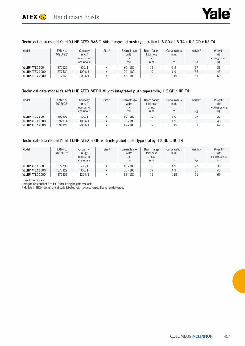
Technical data model Yalelift LHP ATEX BASIC with integrated push type trolley II 3 GD c IIB T4 / II 2 GD c IIA T4
Model EAN-No. 4025092*
Capacity in kg/
number of chain falls
Size ¹ Beam flange width
bmm
Beam flange thickness
t max.mm
Curve radius min.
m
Weight ²
kg
Weight ² with
locking devicekg
YLLHP ATEX 500 *377522 500/1 A 60 - 180 19 0.9 27 33YLLHP ATEX 1000 *377539 1000/1 A 70 - 180 19 0.9 35 43YLLHP ATEX 2000 *377546 2000/1 A 82 - 180 19 1.15 61 69
Technical data model Yalelift LHP ATEX MEDIUM with integrated push type trolley II 2 GD c IIB T4
Model EAN-No. 4025092*
Capacity in kg/
number of chain falls
Size ¹ Beam flange width
bmm
Beam flange thickness
t max.mm
Curve radius min.
m
Weight ²
kg
Weight ² with
locking devicekg
YLLHP ATEX 500 *592291 500/1 A 60 - 180 19 0.9 27 33YLLHP ATEX 1000 *592314 1000/1 A 70 - 180 19 0.9 35 43YLLHP ATEX 2000 *592321 2000/1 A 82 - 180 19 1.15 61 69
Technical data model Yalelift LHP ATEX HIGH with integrated push type trolley II 2 GD c IIC T4
Model EAN-No. 4025092*
Capacity ³ in kg/
number of chain falls
Size ¹ Beam flange width
bmm
Beam flange thickness
t max.mm
Curve radius min.
m
Weight ²
kg
Weight ² with
locking devicekg
YLLHP ATEX 500 *377799 500/1 A 60 - 180 19 0.9 27 33YLLHP ATEX 1000 *377829 900/1 A 70 - 180 19 0.9 35 43YLLHP ATEX 2000 *377836 1250/1 A 82 - 180 19 1.15 61 69
¹ Size B on request² Weight for standard 3 m lift. Other lifting heights available.³ Models in HIGH design are already labelled with reduced capacities when delivered.
ATEX Hand chain hoists

458
Technical data model Yalelift LHG ATEX BASIC with integrated geared type trolley II 3 GD c IIB T4 / II 2 GD c IIA T4
Model EAN-No. 4025092*
Capacity in kg/
number of chain falls
Size ¹ Beam flange width
bmm
Beam flange thickness
t max.mm
Curve radius min.
m
Weight ²
kg
Weight ² with
locking devicekg
YLLHG ATEX 500 *377744 500/1 A 60 - 180 19 0.9 31 38YLLHG ATEX 1000 *377768 1000/1 A 70 - 180 19 0.9 40 48YLLHG ATEX 2000 *378697 2000/1 A 82 - 180 19 1.15 65 73YLLHG ATEX 3000 *377782 3000/1 A 100 - 180 19 1.5 112 121YLLHG ATEX 5000 *378703 5000/2 A 110 - 180 27 2.0 157 167YLLHG ATEX 10000 *378727 10000/3 B 190 - 310 40 1.8 232 on request
Technical data model Yalelift LHG ATEX MEDIUM with integrated geared type trolley II 2 GD c IIB T4
Model EAN-No. 4025092*
Capacity in kg/
number of chain falls
Size ¹ Beam flange width
bmm
Beam flange thickness
t max.mm
Curve radius min.
m
Weight ²
kg
Weight ² with
locking devicekg
YLLHG ATEX 500 *594592 500/1 A 60 - 180 19 0.9 31 38YLLHG ATEX 1000 *594608 1000/1 A 70 - 180 19 0.9 40 48YLLHG ATEX 2000 *594615 2000/1 A 82 - 180 19 1.15 65 73YLLHG ATEX 3000 *594622 3000/1 A 100 - 180 19 1.5 112 121YLLHG ATEX 5000 *594639 5000/2 A 110 - 180 27 2.0 157 167YLLHG ATEX 10000 *941549 10000/3 B 190 - 310 40 1.8 232 on request
Technical data model Yalelift LHG ATEX HIGH with integrated geared type trolley II 2 GD c IIC T4
Model EAN-No. 4025092*
Capacity ³ in kg/
number of chain falls
Size ¹ Beam flange width
bmm
Beam flange thickness
t max.mm
Curve radius min.
m
Weight ²
kg
Weight ² with
locking devicekg
YLLHG ATEX 500 *377843 500/1 A 60 - 180 19 0.9 31 38YLLHG ATEX 1000 *377867 900/1 A 70 - 180 19 0.9 40 48YLLHG ATEX 2000 *377874 1250/1 A 82 - 180 19 1.15 65 73YLLHG ATEX 3000 *377898 2000/1 A 100 - 180 19 1.5 112 121YLLHG ATEX 5000 *377911 4000/2 A 110 - 180 27 2.0 157 167YLLHG ATEX 10000 *377928 6000/3 B 190 - 310 40 1.8 232 on request
¹ Size B on request² Weight for standard 3 m lift. Other lifting heights available.³ Models in HIGH design are already labelled with reduced capacities when delivered.
Copper-coated for MEDIUM design or higher!
ATEX Hand chain hoists
INFO
Yale hoists and trolleys are not designed for passenger elevation applications and must not be used for this purpose.

459
Dimensions model Yalelift LH ATEX
Model YLLH ATEX 500 YLLH ATEX 1000 YLLH ATEX 2000 YLLH ATEX 3000 YLLH ATEX 5000 YLLH ATEX 10000
A min., mm 188 211 264 316 425 565A1, mm 223 250 289 346 345 365A2, mm 381 427 511 614 612 665B, mm 17 22 30 38 45 68C, mm 24 29 35 40 47 68D, mm 14 19 22 30 37 50F (Geared trolley), mm 92 92 91 107 150 150H1, mm 24 24 24 32 31 45I (Push trolley), mm 72 72 96 131 143 170I (Geared trolley), mm 77 77 98 133 149 170L, mm 270 310 360 445 525 485L1, mm 130 130 150 180 209 225L2, mm 444 488 582 690 720 805L3, mm 124 135 172 203 175 215L4, mm 184 201 230 265 283 348M, mm M 18 M 22 M 27 M 30 M 42 M 48O, mm 60 60 80 112 125 150P (Geared trolley), mm 108 110 112 112 117 165T (Area A), mm 280 290 305 320 364 440T (Area B), mm 400 410 425 440 484 540
Model Yalelift LHG ATEX, 500 - 3000 kg, single fall
Model Yalelift LHP ATEX, 500 - 3000 kg, single fall
Model Yalelift LHG ATEX, 10000 kg, three fall
Model Yalelift LHP/LHG ATEX, 5000 kg, double fall
ATEX Hand chain hoists

460
Technical data model HTP ATEX BASIC II 3 GD c IIB T4 / II 2 GD c IIA T4
Model EAN-No. 4025092*
Capacity
kg
Size Beam flange width
bmm
Beam flange thickness
t max.mm
Curve radius min.
m
Hand effort at WLL
daN
Weight
kg
Weight with
locking devicekg
HTP ATEX 500 *362504 500 A 50 - 220 25 0.9 – 8.0 14.5HTP ATEX 1000 *362535 1000 A 50 - 220 25 0.9 – 9.0 17.0HTP ATEX 2000 *362542 2000 A 66 - 220 25 1.15 – 16.0 24.0HTP ATEX 500 *362559 500 B 160 - 300 40 0.9 – 10.6 17.1HTP ATEX 1000 *362573 1000 B 160 - 300 40 0.9 – 12.0 20.0HTP ATEX 2000 *362580 2000 B 160 - 300 40 1.15 – 19.3 27.3
Technical data model HTP ATEX HIGH II 2 GD c IIC T4
Model EAN-No. 4025092*
Capacity
kg
Size Beam flange width
bmm
Beam flange thickness
t max.mm
Curve radius min.
m
Hand effort at WLL
daN
Weight
kg
Weight with
locking devicekg
HTP ATEX 500 *573894 500 A 50 - 220 25 0.9 – 8.0 14.5HTP ATEX 1000 *573900 1000 A 50 - 220 25 0.9 – 9.0 17.0HTP ATEX 2000 *573917 2000 A 66 - 220 25 1.15 – 16.0 24.0HTP ATEX 500 *362764 500 B 160 - 300 40 0.9 – 10.6 17.1HTP ATEX 1000 *362771 1000 B 160 - 300 40 0.9 – 12.0 20.0HTP ATEX 2000 *362788 2000 B 160 - 300 40 1.15 – 19.3 27.3
Push and geared type trolley model HTP/G ATEXCapacity 500 - 20000 kgThe trolley enables the exact positioning or easy traver-sing of large loads with either manual or powered hoisting equipment.
Features• The trolley wheels (only for HIGH design) are designed
for a max. beam profile incline of 14 % (DIN 1025-1), excellent rolling features due to prelubricated and encapsulated ball bearings.
• Adjustable to fit a wide range of beam widths and profiles (e. g. INP, IPE and IPB).
• Adjustments are made by rotating the clevis load bar which also ensures the centred positioning of the hoist in the clevis – no creeping to the left or the right.
• Explosion protected version with spark resistant coating.
• Trolleys equipped with rubber buffers.
• Stainless steel hand chain for model HTG.
Option• Locking device to secure the trolley in position on the
beam (park position e.g. on ships).
Image shows HIGH design
ATEX Trolleys

461
Technical data model HTG ATEX BASIC II 3 GD c IIB T4 / II 2 GD c IIA T4
Model EAN-No. 4025092*
Capacity
kg
Size Beam flange width
bmm
Beam flange thickness
t max.mm
Curve radius min.
m
Hand effort at WLL
daN
Weight*
kg
Weight* with
locking devicekg
HTG ATEX 500 *362597 500 A 50 - 220 25 0.9 3 9.7 16.2HTG ATEX 1000 *362603 1000 A 50 - 220 25 0.9 6 11.2 19.2HTG ATEX 2000 *362610 2000 A 66 - 220 25 1.15 7 18.0 26.0HTG ATEX 3000 *362627 3000 A 74 - 220 25 1.4 7 35.4 44.6HTG ATEX 5000 *362634 5000 A 90 - 220 25 1.8 9 51.8 62.3HTG ATEX 500 *362641 500 B 160 - 300 40 0.9 3 12.6 19.1HTG ATEX 1000 *362658 1000 B 160 - 300 40 0.9 6 14.1 22.1HTG ATEX 2000 *362665 2000 B 160 - 300 40 1.15 7 21.3 29.3HTG ATEX 3000 *362672 3000 B 160 - 300 40 1.4 7 39.2 48.4HTG ATEX 5000 *362689 5000 B 180 - 300 40 1.8 9 56.0 66.5HTG ATEX 8000 *362719 8000 B 125 - 310 40 1.8 14 104.0 –HTG ATEX 10000 *362726 10000 B 125 - 310 40 1.8 14 104.0 –HTG ATEX 15000 *377577 15000 B 125 - 310 40 5.0 29 230.0 –HTG ATEX 20000 *377584 20000 B 125 - 310 40 5.0 29 230.0 –
Technical data model HTG ATEX HIGH II 2 GD c IIC T4
Model EAN-No. 4025092*
Capacity
kg
Size Beam flange width
bmm
Beam flange thickness
t max.mm
Curve radius min.
m
Hand effort at WLL
daN
Weight ¹
kg
Weight ¹ with
locking devicekg
HTG ATEX 500 *573948 500 A 50 - 220 25 0.9 3 9.7 16.2HTG ATEX 1000 *573955 1000 A 50 - 220 25 0.9 6 11.2 19.2HTG ATEX 2000 *573962 2000 A 66 - 220 25 1.15 7 18.0 26.0HTG ATEX 3000 *573979 3000 A 74 - 220 25 1.4 7 35.4 44.6HTG ATEX 5000 *573986 5000 A 90 - 220 25 1.8 9 51.8 62.3HTG ATEX 500 *362825 500 B 160 - 300 40 0.9 3 12.6 19.1HTG ATEX 1000 *362795 1000 B 160 - 300 40 0.9 6 14.1 22.1HTG ATEX 2000 *362801 2000 B 160 - 300 40 1.15 7 21.3 29.3HTG ATEX 3000 *377591 3000 B 160 - 300 40 1.4 7 39.2 48.4HTG ATEX 5000 *362818 5000 B 180 - 300 40 1.8 9 56.0 66.5HTG ATEX 8000 *573702 8000 B 125 - 310 40 1.8 14 104.0 –HTG ATEX 10000 *573719 10000 B 125 - 310 40 1.8 14 104.0 –HTG ATEX 15000 *573726 15000 B 125 - 310 40 5.0 29 230.0 –HTG ATEX 20000 *573733 20000 B 125 - 310 40 5.0 29 230.0 –
¹ Weight HTG without hand chain
ATEX Trolleys
INFO
Yale hoists and trolleys are not designed for passenger elevation applications and must not be used for this purpose.

462
Dimensions model HTP ATEX
Model HTP ATEX 500-A
HTP ATEX 1000-A
HTP ATEX 2000-A
HTP ATEX 3000-A
HTP ATEX 5000-A
HTP ATEX 500-B
HTP ATEX 1000-B
HTP ATEX 2000-B
HTP ATEX 3000-B
HTP ATEX 5000-B
A, mm 77 82.5 98.5 114 132.5 92 97.5 113.5 129 147.5D, mm 16 17 22 26 33 16 17 22 26 33D1, mm 25 30 40 48 60 25 30 40 48 60D2, mm 30 35 47 58 70 30 35 47 58 70F1, mm 46 46 46 46 45.5 46 46 46 46 45.5H1, mm 30.5 30.5 30.5 30 30 45.5 45.5 45.5 45 45I (HTP ATEX), mm 71.5 71.5 95.5 131 142.5 71.5 71.5 95.5 131 142.5L, mm 260 260 310 390 450 260 260 310 390 450L1, mm 130 130 150 180 209 130 130 150 180 209O, mm 60 60 80 112 125 60 60 80 112 125P1, mm 168 168 168 168 168 168 168 168 168 168P2, mm 146 150 155 160 167.5 187 187 189.5 191.5 191.5L3, mm 346 346 396 476 556 346 346 396 476 556
Dimensions model HTG ATEX
Model HTG ATEX 500-A
HTG ATEX
1000-A
HTG ATEX
2000-A
HTG ATEX
3000-A
HTG ATEX
5000-A
HTG ATEX 500-B
HTG ATEX
1000-B
HTG ATEX
2000-B
HTG ATEX
3000-B
HTG ATEX
5000-B
HTG ATEX
8000-B
HTG ATEX
10000-B
HTG ATEX
15000-B
HTG ATEX
20000-B
A, mm 77 82.5 98.5 114 132.5 92 97.5 113.5 129 147.5 276 276 270 270B, mm – – – – – – – – – – 52 52 70 70D, mm 16 17 22 26 33 16 17 22 26 33 30 30 35 35D1, mm 25 30 40 48 60 25 30 40 48 60 80 80 110 110D2, mm 30 35 47 58 70 30 35 47 58 70 114 114 155 155F (HTG ATEX), mm 91.5 91.5 90.5 107.5 149.5 91.5 91.5 90.5 107.5 149.5 113 113 113 113F1, mm 46 46 46 46 45.5 46 46 46 46 45.5 77 77 – –H1, mm 30.5 30.5 30.5 30 30 45.5 45.5 45.5 45 45 45 45 45 45I (HTG ATEX), mm 76.5 76.5 98 132.5 148.5 76.5 76.5 98 132.5 148.5 170 170 170 170L, mm 260 260 310 390 450 260 260 310 390 450 430 430 870 870L1, mm 130 130 150 180 209 130 130 150 180 209 200 200 200 200L2, mm – – – – – – – – – – – – 115 115O, mm 60 60 80 112 125 60 60 80 112 125 150 150 150 150P (HTG ATEX), mm 110 110 110 110 110 110 110 110 110 110 163 163 163 163P1, mm 168 168 168 168 168 168 168 168 168 168 193 193 – –P2, mm 146 150 155 160 167.5 187 187 189.5 191.5 191.5 – – – –T, mm – – – – – – – – – – 270 270 270 270L3, mm 346 346 396 476 556 346 346 396 476 556 536 536 976 976P3, mm 194 194 194 195 195 194 194 194 195 195 – – – –
P
P
b
D1
2
2
H1
A
t
OIF
D
D
L 1
LP b
F
P1
H1
t
F 1
P2
O I
L
L1
D1
D2
B
L2
Model HTP/HTG ATEX 500 - 5000 kg Model HTP/HTG ATEX 500 - 5000 kg, with locking device
Model HTG ATEX 10000 kg, locking device Model HTG ATEX 10000 kg Model HTG ATEX 20000 kg
P bT
t
F O IA
H1
D
L
L1
D1
D2
B
ATEX Trolleys

463
Technical data model UNOplus ATEX BASIC II 3 GD c IIB T4 und I M2
Model EAN-No. 4025092*
Capacity in kg/
number of chain falls
Chain dimensions
d x pmm
Load chain grade
Lift with one full lever turn
mm
Handle pull at WLL
daN
Weight at standard lift
(1.5 m)kg
UNOplus ATEX 750 *336536 750/1 6 x 18 T 20 20 7.2UNOplus ATEX 1500 *336543 1500/1 8 x 24 T 22 35 12.5UNOplus ATEX 3000 *336550 3000/1 10 x 30 T 17 40 21.5UNOplus ATEX 6000 *336567 6000/2 10 x 30 T 9 40 32.0
Model UNOplus ATEX 750 UNOplus ATEX 1500 UNOplus ATEX 3000 UNOplus ATEX 6000
A min., mm 340 410 510 690B, mm 22 28 36 45C, mm 26 32 40 44D, mm 16 21 27 33E, mm 250 330 380 380F, mm 150 170 220 220G, mm 70 80 100 100H, mm 80 90 120 120J, mm 150 180 210 210K, mm 60 80 90 90L, mm 90 100 120 120
Dimensions model UNOplus ATEX
Ratchet lever hoist model UNOplus ATEXCapacity 750 - 6000 kgFurther technical development turns the ratchet lever hoist into the successor of our proven UNO model. The versatile tool for lifting, pulling and securing of loads is characterised by its compact design and robust stam-ped steel construction.
Features• Due to optimized gearing and improved bearings in the
housing cover a minimum effort is required to operate the short hand lever.
• Steel hand wheel as standard.
• Automatic screw-and-disc type load brake with corrosion protected components.
• Standard free chaining device to quickly attach the load or to pull the chain through the hoist in both directions.
• Robust chain guide rollers eliminate fouling and jamming of chain on the load sheave.
• Sturdy bottom block with encapsulated bolt connections.
• Alloyed steel link chain in accordance with national and international standards and regulations.
• Drop forged suspension and load hooks are made from non-aging, high tensile steel and fitted with robust safety latches.
ATEX Ratchet lever hoists
INFO
Yale hoists and trolleys are not designed for passenger elevation applications and must not be used for this purpose.
464
ATEX Electric winches
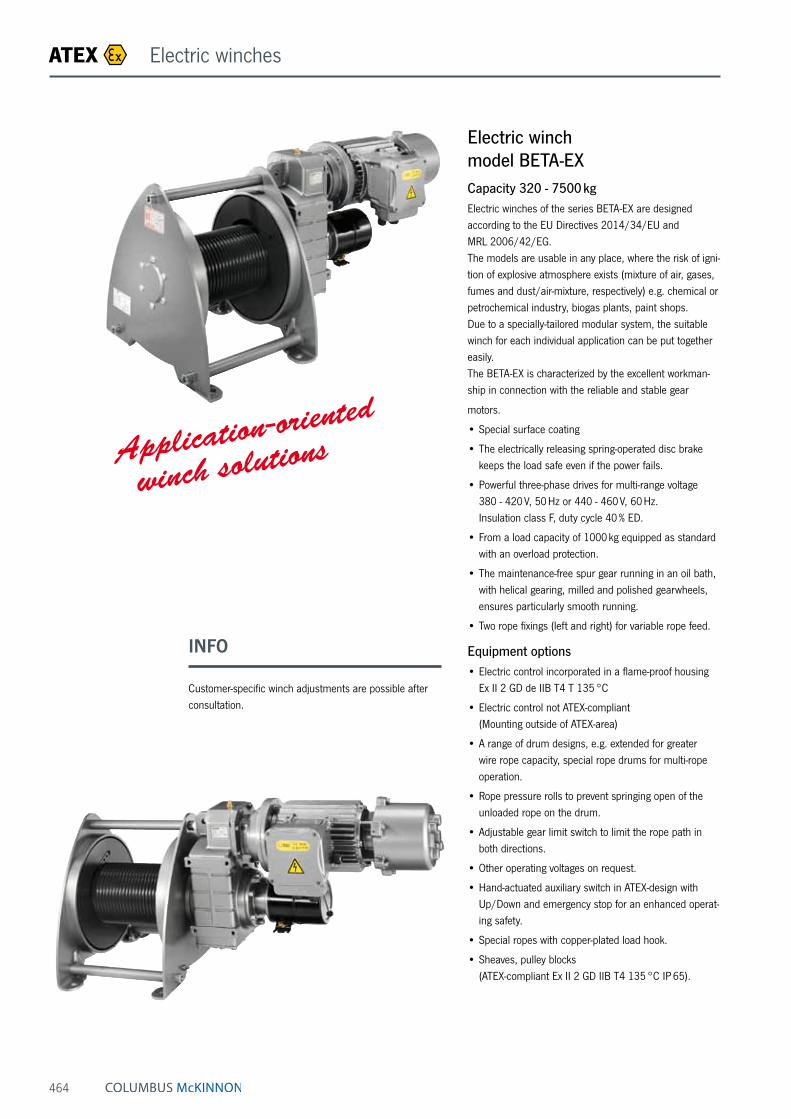
Electric winch model BETA-EXCapacity 320 - 7500 kgElectric winches of the series BETA-EX are designed according to the EU Directives 2014/34/EU and MRL 2006/42/EG. The models are usable in any place, where the risk of igni-tion of explosive atmosphere exists (mixture of air, gases, fumes and dust/air-mixture, respectively) e.g. chemical or petrochemical industry, biogas plants, paint shops. Due to a specially-tailored modular system, the suitable winch for each individual application can be put together easily. The BETA-EX is characterized by the excellent workman-ship in connection with the reliable and stable gear
motors.
• Special surface coating
• The electrically releasing spring-operated disc brake keeps the load safe even if the power fails.
• Powerful three-phase drives for multi-range voltage 380 - 420 V, 50 Hz or 440 - 460 V, 60 Hz. Insulation class F, duty cycle 40 % ED.
• From a load capacity of 1000 kg equipped as standard with an overload protection.
• The maintenance-free spur gear running in an oil bath, with helical gearing, milled and polished gearwheels, ensures particularly smooth running.
• Two rope fixings (left and right) for variable rope feed.
Equipment options• Electric control incorporated in a flame-proof housing
Ex II 2 GD de IIB T4 T 135 °C
• Electric control not ATEX-compliant (Mounting outside of ATEX-area)
• A range of drum designs, e.g. extended for greater wire rope capacity, special rope drums for multi-rope operation.
• Rope pressure rolls to prevent springing open of the unloaded rope on the drum.
• Adjustable gear limit switch to limit the rope path in both directions.
• Other operating voltages on request.
• Hand-actuated auxiliary switch in ATEX-design with Up/Down and emergency stop for an enhanced operat-ing safety.
• Special ropes with copper-plated load hook.
• Sheaves, pulley blocks (ATEX-compliant Ex II 2 GD IIB T4 135 °C IP 65).
Application-oriented
winch solutions
INFO
Customer-specific winch adjustments are possible after consultation.

465
Sheave block-EX for rope guidance, equipped with ball bearings, incl. earthing screw and copper-coated sheave model DSRBX S
Dimensions model DSRBX S
Model DSRBX S 90/4
DSRBX S 145/5
DSRBX S 145/6
DSRBX S 185/8
DSRBX S 185/9
DSRBX S 270/12
DSRBX S 325/14
DSRBX S 400/16
DSRBX S 400/18
DSRBX S 490/20
Art.-No. 0400431113 0400431114 0400431115 0400431117 0400431118 0400431121 0400431123 0400431124 0400431125 0400431126B, mm 85 125 125 138 138 191 260 302 302 313C, mm 90 160 160 195 195 290 350 430 430 580Ø D, mm 90 145 145 185 185 270 325 400 400 490Ø D1, mm 20 25 25 30 30 40 50 50 50 65Ø Dm, mm 80 125 125 160 162 246 297 368 364 450E, mm 62 88 88 106 106 138 180 212 212 220H, mm 134 224 224 273 273 407 490 612 612 694K, mm 65 110 110 135 135 202 242 310 310 340L, mm 120 200 200 245 245 360 440 530 530 650Ø M/M1, mm 9/9 11.5/13 11.5/13 13.5/15 13.5/15 18/20 22/25 26/30 26/30 34/40S, mm 4 6 6 8 8 10 12 15 15 16
Model Art.-No. Classification
FEM/ISO
Pulling force in kg
at deflection
90°
Pulling force in kg
at deflection
180°
Rope diameter
mm
DSRBX S 90/4 0400431113 2m/M5 700 500 4DSRBX S 145/5 0400431114 4m/M6 1100 800 5DSRBX S 145/6 0400431115 2m/M5 1100 800 6DSRBX S 185/8 0400431117 2m/M5 2300 1630 8DSRBX S 185/9 0400431118 1 Am/M4 2300 1630 9DSRBX S 270/12 0400431121 2m/M5 2500 1800 12DSRBX S 325/14 0400431123 2m/M5 4500 3200 14DSRBX S 400/16 0400431124 3m/M6 5000 3800 16DSRBX S 400/18 0400431125 2m/M5 5000 3800 18DSRBX S 490/20 0400431126 3m/M6 8000 6000 20
Technical data model DSRBX S MEDIUM II 2 GD c IIB T4
F Rope
F Rope
Rope-Ø
ATEX Electric winches/Accessories

466
Manual winch with load pressure brake model OMEGA-EXCapacity 1000 daNThe hand winch OMEGA-EX is a complete new construc-tion and was developed especially for the high safety requirements in potentially explosive atmospheres. All components of the OMEGA-EX are designed to avoid effectively an inadmissible heating of the surfaces. Carefully selected materials and the sophisticated construction of the winch prevent the occurrence of mechanically caused sparks, for example by intrusion of foreign materials.
Features• Winch housing made of aluminum permanent mold
casting for a low own weight, rope drum made of steel, chemically nickel-plated for a high versatility.
• Integrated load pressure brake
• Closed gear with oil bath lubrication. The large oil volume ensures a high cooling effect.
• Equipotential bonding to avoid electrostatic charging.
• Pivotable crank handle
• Suitable for ambient temperatures of -20 °C up to +40 °C.
Model OMEGA-EX 10
A, mm 345B, mm 300C, mm 110D, mm 65E, mm 156F, mm 424G, mm 90H, mm 95I, mm 126J, mm 320Ø K, mm 17L, mm 85M, mm 116N, mm 88O, mm 310.5P, mm 56Q, mm 56R, mm 117.5Ø S, mm 100T, mm 200
ATEX Manual winches
Model EAN-No. 4053981**
Capacity 1st layer
kg
Capacity top layer
kg
Rope diameter
mm
Lift per crank rotation
mm
Required crank effort
daN
Weight without
ropekg
OMEGA-EX 10 **004570 1000 692 8 ⁵ 29 17 38
⁵ recommended rope: EN 12385-2
Technical data model OMEGA-EX MEDIUM II 2 GD ck IIB T4
Application areasChemical or petrochemical industry, biogas plants, paint shops

467
Wall-mounted rack and pinion jacks model ZWW-EXCapacity 250 kgThe rack and pinion jack is suitable for lifting, lowering, pulling and pushing, for horizontal displacement, supporting, adjusting or fixing of heavy components or whole appliances and equipment in hazardous areas.
Features• Carefully selected materials and a high-grade coating
prevent the occurrence of mechanically caused sparks.
• No inadmissible heating of the surfaces due to the intelligent design of the individual parts.
• Equipotential bonding and limited surface area to avoid electrostatic charging.
• The grease-lubricated, self-locking worm gear is set into operation by rotations on the crank. It provides not only for easy movement of the load, but also for a reliable safety in every position.
Application areasPlant construction, shipping, wastewater treatment plants, chemical industry and food industry.
Technical data model ZWW-EX MEDIUM II 2 GD c IIB T4
Model Art.-No. Capacity
kg
Rack length
mm
Lift
mm
Weight
kg
ZWW-EX 250 040052648 250 735 530 5.7
30 20
735
20
35
200
175
175
225
20
60
123
8
Ø11
Ø11
Ø10
.5
5050
90
28
313
1193226.4
530
Lift
Rack
leng
th
Earthing screw
ATEX Rack & Pinion jacks

468
Hand pallet truck, stainless steel version model HU 20-115 VATP ATEX PROLINECapacity 2000 kgThe hand pallet truck is designed for the use in explosive environments (zone 1 and 2).
Features• Ergonomic safety control handle for one-hand operation
of lifting, driving and lowering.
• Low maintenance high performance hydraulic pump with hard chromium plated piston and pressure relief valve. Hydraulic unit made of V4A-316 stainless steel.
• Frame, adjustable connecting rods, bolts and the tor-sion tube are made of high quality V4A-316 stainless steel.
• Steering angle of 105 degree to each side for easy handling in confined spaces.
• Conductive steering rollers (antistatic).
Technical data HU 20-115 VATP ATEX PL HIGH II 2 GD c IIC T6
Model HU 20-115 VATP ATEX PL
Art.-No. 040054147Capacity, kg 2000Weight, kg 86Tyre type ¹ PA/VGSteering rollers, mm 200 x 50Load rollers, mm 82 x 70Stroke h3, mm 115Height of control handle h14, mm 1200Fork height lowered h13, mm 85Fork width e, mm 160Fork length l, mm 1150Outside dimension of forks b1, mm 540
¹ PA … Polyamide, VG … Solid rubber
ATEX Hand pallet trucks
INFO
Before the use in explosive environments the operator has to create an explosion protection document acc. to the machinery directive 1999/92/EG!

469
ATEX Load moving systems
• The universal joint suspension of the roller groups contributes to a positive contact when travelling over uneven floors.
• Conductive load wheels (antistatic).
• Each individual roller is made from high tensile mate-rial which ensures extremely quiet running.
• The rollers are suitable for all in-plant floors and will not damage normal floor covering.
• The load moving systems can be easily dismantled and facilitate transport even in small trucks.
• The load moving systems have been developed for professional applications and are practically mainte-nance-free.
• All rollers are provided with two encapsulated, lifetime lubricated ball bearings.
• The front steering skate is equipped with an amply di-mensioned axial ball bearing underneath the turntable.
• The front and rear skates are available individually.
Technical data model SX ATEX II 2 GD c IIB T4
Model EAN-No. 4053981**
Capacity
t
Overall height
mm
Number of rollers
Roller diameter
mm
Colour of rollers
Weight
kg
SX-10 ATEX **534107 10 102 16 82 black 54SX-20 ATEX **814063 20 102 32 82 black 76SX-30 ATEX **325163 30 110 48 82 black 136
Model SX-20 ATEX
Steerman® Heavy load moving system model SX ATEXCapacity 10 - 30 tThese universal heavy load moving systems have been designed for the safe and cost saving transport of loads. Transport of heavy loads (e.g. machines, construction parts, steel structures) is normally made with a stable three point loading system. Transport of extremely bulky or heavy loads with an unfavourable center of balance, may also be executed with a four point loading system. The robust towing bar in connection with the unique turn-table on large diameter thrust bearings allows effortless steering of the load. The rear skates are aligned parallel by means of a tie rod and kept in position, thus ensuring time saving and smooth transportation of the load.
The skates are powder coated and all connecting ele-ments corrosion-resistant. Highest safety requirements have been considered.
Features• The modular design ensures an extremely simple
operation and simultaneously offers a wider range of combinations.
• The construction of the load moving systems is ex-tremely robust and resistant to distortion.
• The skates are smooth-running and provide an incred-ibly low rolling resistance even with the heaviest loads.
• Twin rollers (instead of one wide roller) ensure low roll-ing resistance even at a narrow curve radius.

Pfaff-silberblau Hebezeugfabrik GmbHAm Silberpark 2-8, 86438 KissingPhone +49 / 83 33 / 21 21-800, Fax +49 / 83 33 / 21 21-805 E-Mail: [email protected], Internet: www.pfaff-silberblau.com
Questionnaire - Page 1
5.2CHECKLISTforexplosionprotectiondata
■Devicegroup,devicecategoryandzoneallocation(seeItem2.1)
Pleaseenteracross
Notavailable
Devicegroup
Device group I
DevicegroupII X
Pleasecomplete
Ignitiontemperatureofthedust/airmixture
Max.surfacetemperaturefordust[°C]
Firm: __________________________________________________________________________________________________________________________
Address: __________________________________________________________________________________________________________________________
Department: ____________________________________________________________________________ Phone: _______________________________________
Fax: ____________________________________________________________________________ E-mail: _______________________________________
Name: __________________________________________________________________________________________________________________________
ToenablePfaff-silberblauliftingunits/driveelementstobedesignedinaccordancewithECdirective94/9/ECitisimperativethatthischecklistis
completedandalloutstandingquestionsregardingexplosionprotectionbeansweredconscientiously.
Temp.class Max.surfacetemperatureoftheequipment[°C] Ignitiontemperatureofthecombustible
substances[°C]
T1 450 > 450
T2 300 > 300... < 450
T3 200 > 200... < 300
T4 135 > 135... < 200
T5 100 > 100... < 135
T6 85 > 85... < 100
■Temperatureclassesandexplosiongroups(seeItem2.4)
Pleaseenteracross
Notavailable
Notavailable
Category/Zone Ex-atmosphere....
Category1(=Zone0/20) ...is the permanent, long-term or frequent situation.
Category2(=Zone1/21) ...isanoccasionaloccurrence.
Category3(=Zone2/22) ...isarareoccurrenceandthenonlytemporarily.
Notavailable
the equipment
explosion
2 WhatkindofpotentiallyexplosiveareasdowesupplyPfaff-silberblaudriveelementsfor?
• Our customer undertakes to provide us with all the required data. • Our customer must check the applicability based on the information provided by us. • The operator is responsible for - complying with the maximum capacity of the drive mechanism/lifting system - avoiding explosive atmospheres - minimizing or limiting the time of the explosion hazard - observing the information in the operating instructions supplied by us. Iftheoperatinginstructionsarenotadheredto,thedeclarationofconformitywillceasetobevalidin accordancewith94/9/EC. • During the offer/order stage, Pfaff-silberblau creates a checklist, which subsequently forms part of the order documentation.
1Responsibility
2.2Devicecategory
Category 2 includes Category 3.2.3Zoning Zonesinpotentiallyexplosiveatmospheres
Zone Probability of occurrence of a potentially explosive atmosphere
Gas Dust
0 20 Permanent,long-term,frequent(prevailingsituation)
1 21 Occasional,duringnormaloperations
2 22 Seldom,temporary
Pfaff-silberblau drive elements are designed on the basis of an D housing temperature of 80 °C, such that if the room temperature is 40 °C the surface temperature
will be 120 °C. This results in a safety factor of 1.12 relative to the max. surface temperature of 135 °C.
For explosion-proofing in respect of dust, the operator is required to provide information on the maximum ignition temperature of the air/dust mixture.
2.4Temperatureclassesandexplosiongroups Temperature Max.surfacetemperature Ignitiontemperatureof Explosiongroup
class oftheequipment[°C] thecombustiblesubstances[°C] IIA IIB IIC
T1 450 > 450 Ammonia, acetone-benzole, Coke oven gas, Hydrogen
ethane, ethyl acetate, carbon water gas (enriched)
monoxide, methane, methanol,
methyl benzene, propane
T2 300 > 300... < 450 n-butane, n-butanol, Butadiene 1,3 Acetylene
cyclohexanone, ethanol, ethylene,
acetic anhydride, ethylene oxide
natural gas, liquid gas
T3 200 > 200... < 300 Petrol, diesel, heating oil, Crude oil, isoprene,
aircraft fuel, n-hexane hydrogen sulphide
T4 135 > 135... < 200 Acetaldehyde ether Ethyl ether
T5 100 > 100... < 135
T6 85 > 85... < 100 Carbon bisulphide
2.1Deviceclass
Devicegroup Use Remarks
I Mining Not available
II All other devices Available
DevicegroupII
Safety Zone
Category1
(=Zone0/20)
Category2
(=Zone1/21)
Category3
(=Zone2/22)
Devices providing an ultra-highlevel of
safety.
In association with infrequentdrivefaults!
Devices providing a highlevel of safety.
In association with expecteddevicefaults!
Devices providing a normallevel of safety.
In association with normaloperation!
Designed for use in areas in which there is a permanent,long-termorfrequentpresence of
a potentially explosive atmosphere consisting of a mixture of air and gases, vapors or mist or of
dust/air mixtures.
Designed for use in areas in which there is an occasionalpresence of a potentially explosive
atmosphere consisting of a mixture of air and gases, vapors or mist or of dust/air mixtures.
Designed for use in areas in which a potentially explosive atmosphere caused by gases, vapors,
mist or raised dust can be ruled out or, where such an atmosphere should nevertheless occur,
the likelihoodofsuchoccurrenceisveryrareandwillbeforashorttimeonly.
2 What kind of potentially explosive areas do we supply Pfaff-silberblau
• Our customer undertakes to provide us with all the required data. • Our customer must check the applicability based on the information provided by us. • The operator is responsible for
- complying with the maximum capacity of the drive mechanism/lifting system- avoiding explosive atmospheres- minimizing or limiting the time of the explosion hazard- observing the information in the operating instructions supplied by us.If the operating instructions are not adhered to, the declaration of conformity
accordance with 94/9/EC. • During the offer/order stage, Pfaff-silberblau creates a checklist, which subsequently forms part of the order
documentation.
1 Responsibility
2.2 Device category
2.3 ZoningZones Zones in potentially explosive atmospheres
Zone Probability of occurrence of a potentially explosive atmosphere
Gas Dust
0 20 Permanent, long-term, frequent (prevailing situation)
1 21 Occasional, during normal operations
2.1 Device class
Device Device Device group Use Remarks
I Mining Not available
II All other devices Available
Device group II
Safety Zone
Category 1
(= Zone 0/20)
Category 2
(= Zone 1/21)
Category 3
(= Zone 2/22)
Devices providing an ultra-high level of
safety.
In association with infrequent drive faults!
Devices providing a high level of safety.
In association with expected device faults!
Devices providing a normal level of safety.
In association with normal operation!
Designed for use in areas in which there is a permanent,
a potentially explosive atmosphere consisting of a mixture of air and gases, vapors or mist or of
dust/air mixtures.
Designed for use in areas in which there is an occasional
atmosphere consisting of a mixture of air and gases, vapors or mist or of dust/air mixtures.
Designed for use in areas in which a potentially explosive atmosphere caused by gases, vapors,
mist or raised dust can be ruled out or, where such an atmosphere should nevertheless occur,
the likelihood of such occurrence is very rare
3Whichcertificationorcheckisrequiredforwhichzone?
Directive 94/9/EC Chapter II Item 8 and Appendix VII
*G = Gas / D = Dust
Category 2 3
Zone 1 21 2 22
Explosiveatmosphere* G D G D
Motor
EC type examination EC type examination
certificate from a nominated office certificate from a nominated office
Internal process control by manufacturer (Directive 94/9/EC Appendix VIII)
Drive Declaration of conformity from the manufacturer and filing of the explosion
prevention documentation with a nominated office
Internal process control by manufacturer
(Directive 94/9/EC Appendix VIII)
Declaration of conformity
from the manufacturer
Questionnaire - Page 1
2.5Typeofprotection
• Pfaff-silberblau drive elements are designed in accordance with typeofprotection„c-Protectionbyconstructionalsafety“.
• Drive elements produced for use in Zones1and2(gas) are designed in accordance with typeofprotection„k-Protectionbyliquidimmersion“
(drive elements with oil lubrication).
• Typeofprotection„b-Protectionbycontrolofignitionsource“ can be provided by means of control of motor performance.
EN13463-2 Protection by flow restricting enclosure „fr“
EN13463-3 Protection by flameproof enclosure „d“
EN13463-4 Protection by inherent safety „g“
EN13463-5 Protection by constructional safety „c“
EN13463-6 Protection by control of ignition source „b“
EN13463-7 Protection by pressurization „p“
EN13463-8 Protection by liquid immersion „k“
for non-electrical equipment for use in potentially explosive areas:
4HazardanalysisaccordingtoDINEN1127
The purpose of the hazard analysis is to establish which risks of ignition apply to Pfaff-silberblau drive elements and the
safety precautions to be taken to provide the level of safety required.
Hot surface
Mechanically generated sparks caused by friction, impact and degradation
Riskofignitionfrom: Electrostatic charging
Chemical reaction
Improper assembly/installation
5Documentationforsecuringprotectionagainstexplosion
• Checklist for provision of all data of relevance to explosion
protection.
• Questionnaire for the specification of technical data.
• Written order contract for the design of the drive elements.
• Documented calculations for the specification of the
thermal limits and the life of the bearings.
• Production checklist for testing the components: Sealing faces, roughness of the spindle and
bearing nuts, bearing face of the gearing.
• Operating manual with 94/9/EC declaration of conformity.
• Rating plate.
5.1Identifyingmarkings
Ex-marking
Device group
Category
Ex-atmosphere
Type of protection
Temperature class
Max. surface temperature on which 5 mm of dust can settle
II 2 G/D ckT4/100°C
Please complete
temperature of the dust/air mixture
temperature for dust [°C]
> 200... < 300
> 135... < 200
> 100... < 135
> 85... < 100
Not available
Not available
temperature
surface temperature
Category 2 includes Category 3.
housing temperature of 80 °C, such that if the room temperature is 40 °C the surface temperature
Carbon bisulphide
of
a potentially explosive atmosphere consisting of a mixture of air and gases, vapors or mist or of
of a potentially explosive
Designed for use in areas in which a potentially explosive atmosphere caused by gases, vapors,
mist or raised dust can be ruled out or, where such an atmosphere should nevertheless occur,
Checklist
Worm gear screw jacks/Linear Drivesaccording to 94/9/EC (ATEX)for use in potentially explosive areas
Safety - Made by Pfaff-silberblau
470
ChecklistPfaff-silberblau develops, produces and sets up system solutions and complete actuator units according to indivi-dual customer requirements for different applications: product technique, transport technique, foundry technique, mining, hydraulic engineering, shipbuilding, research, building service, etc.Of course, also available in accordance with regulation 2014/34/EU (ATEX) for the use in areas with an explosi-on hazard.
Simply ask for our checklist for screw jacks and linear drives!
ATEX Screw jacks and linear drives

471
Technical questionnaireTo enable us to design lifting units/drive elements in accordance with EU-directive 2014/34/EU it is essential that this checklist is completed and all open questions regarding explosion protection are answered carefully.
Equipment group, categories and zones
Equipment group I Equipment group II
(only for mining fire damp protection)
Category - Zone Ex-atmosphere ...
— Category 1 - Zone 0/20 … is present continuously for long periods or frequently (not available)
Category M1 Category 2 - Zone 1/21 … is present occasionally in normal operation
Category M2 Category 3 - Zone 2/22 … is unlikely to be present except for a short period of time.
Ex-atmosphere
Medium? If dusts are involved - please specify Surrounding temperature (only permiss- able between
-20 up to +40 °C)
Zone Explosion group
Gases/Vapours G Dust D
— 0 — 20 IIA
1 21 IIB
2 22 IIC
Temperature classes
Temperature class Max. surface temperature of the equipment [°C]
Max. ignition temperature of combustible substances [°C]
Max. surface temperature for dust [°C]
T1 450 > 450 Ignition temperature …….……….Smouldering temperature ……………
T2 300 > 300... < 450
T3 200 > 200... < 300
T4 135 > 135... < 200
— T5 100 > 100... < 135
— T6 85 > 85... < 100
T1 up to T4 available, T5 and T6 not available
Place, Date Signature
ATEX Questionnaire