assessment of the fatigue parameters from random …lab.fs.uni-lj.si/ladisk/data/pdf/assessment of...
TRANSCRIPT
*Corr. Author’s Address: University of Ljubljana, Faculty of Mechanical Engineering, Aškerčeva ulica 6, 1000 Ljubljana, Slovenia, [email protected] 471
Strojniški vestnik - Journal of Mechanical Engineering 62(2016)7-8, 471-482 Received for review: 2016-05-03© 2016 Journal of Mechanical Engineering. All rights reserved. Received revised form: 2016-06-02DOI:10.5545/sv-jme.2016.3774 Original Scientific Paper Accepted for publication: 2016-06-03
0 INTRODUCTION
In a product’s design and development stages standard accelerated vibration tests [1] and [2] are performed in order to prove that no fatigue failure due to the vibration load will occur within the expected service life. Clearly, for the case of vibration loading the structure’s own dynamic response directly imposes a certain stress load to the structure that is greatly amplified in the vicinity of natural frequencies [3] and [4]. The introduced stress state together with the material’s fatigue parameters directly leads to the damage accumulation rate [5], which can be obtained in time- or in frequency domain [6]. Since the structure’s dynamic response to the random vibration excitation is commonly described in terms of a response power spectrum the damage-counting methods in the frequency domain [7] and [8] are the most convenient for a vibration fatigue analysis. In this way the analyst is able to predict whether the structure will withstand the given vibration test beforehand at the design stage.
During a service life the fatigue failure often occurs at the construction elements used for joining
different parts (e. g. welds, solder joints, rivets), where high stress concentrations appear. The fatigue assessment for the quasi-static harmonic or random loading of welded [9] and riveted joints is well researched field for safety assurance of airplanes [10] and [11] and offshore structures [12]. However, when the stress load leading to the fatigue failure depends not only on the external loading but also on the structure’s own dynamic response the phenomenon exceeds classical fatigue scope and should be regarded as vibration fatigue problem [13]. Accordingly, much initial research in the field of vibration fatigue has been applied to the case of microelectronic solder joints (e. g. ball grid array (BGA), plastic ball grid array (PBGA)) in order to increase the reliability of the electronic components. Liu et al. [14] observed the propagation of a crack in a solder joint for the case of a sinusoidal vibration load. Additionally, Chen et al. [15] combined harmonic vibration testing with a numerically obtained stress response to assess the S-N curve of solder material. Using the harmonic-excitation approach for assessing material’s fatigue parameters Yu et al. [16] estimated the solder joint fatigue life under random vibration loading. By
Assessment of the Fatigue Parameters from Random Vibration Testing: Application to a Rivet Joint
Česnik, M. – Slavič, J. – Boltežar, M.Martin Česnik – Janko Slavič – Miha Boltežar*
University of Ljubljana, Faculty of Mechanical Engineering, Slovenia
In order to estimate a structure’s fatigue life when excited with an acceleration profile the fatigue parameters must be known. However, material’s fatigue exponent and fatigue strength are not always readily available, especially for complex structures that include riveted or welded joints for which additional fatigue tests are needed. This study introduces a new fatigue-parameter assessment method based on random vibration loading and its application to a blind-hole rivet joint that diminishes the need for additional fatigue tests. The presented procedure requires a simple experimental setup; however, a more extensive analysis of the experimental results is necessary. The method of fatigue parameter assessment is presented and applied on real, experimentally obtained data from vibration tests of rivet-joint specimens, excited with a random base-vibration load in the frequency range of a single natural frequency. Special attention was given to the modelling of the rivet joint and the uncertainties arising from the riveting process were considered. With the presented procedure it is possible to obtain the fatigue parameters solely from the results of random-vibration testing with different acceleration profiles and therefore diminishing the need for additional classic fatigue tests. The obtained fatigue parameters indirectly include the stress concentration factor and the damping-loss-factor increase during the damage accumulation. Additionally, by applying the random-vibration load the influences of the natural-frequency shift and the small nonlinearities of the structure are reduced, which can present a major issue in classic harmonic-vibration fatigue testing.Keywords: vibration fatigue testing, fatigue parameters, random base-excitation, frequency-domain counting method
Highlights• A method for fatigue parameter assessment from vibration tests with electro-dynamic shaker is presented.• The tested specimens were excited with acceleration-controlled random signal.• Frequency based Tovo-Benasciutti method was applied to the parametrized numerical model to determine expected fatigue
life of a particular specimen.• The method was applied to actual testing of blind-hole rivet joint with nonlinear response.
Strojniški vestnik - Journal of Mechanical Engineering 62(2016)7-8, 471-482
472 Česnik, M. – Slavič, J. – Boltežar, M.
further work of George et al. [17] and Česnik et al. [4] harmonic vibration testing has been shown to present an adequate alternative to classic fatigue testing for fatigue parameter assessment.
On the other hand, several studies dealing with vibration fatigue for the case of random vibration have been presented. Pagnacco et al. [18] optimised the thickness distribution of a plate structure to prolong the structure’s fatigue life when exposed to random vibration. Furthermore, Paulus and Dasgupta [19] proposed a semi-empirical model for a fatigue-life estimation in the case of random vibration. Han et al. [20] performed a vibration fatigue analysis of a spot-welded structure with an iterative approach. Recently, significant advances with the applicative note to the random vibration fatigue analysis of real components from automotive industry were made by Braccesi et al. [21].
In studies [4] and [15] to [20] the fatigue parameters were obtained either with standard fatigue tests or with harmonic vibration excitation of the specimen. In any case an additional test with a different experimental setup was needed to obtain the fatigue parameters. In this study a new methodology is presented that enables the assessment of fatigue parameters (e. g. fatigue exponent b and fatigue strength C) only from a series of random-signal base-excitation vibration tests in the frequency range of specimen’s dynamic response. Using the developed methodology the need for additional fatigue tests is diminished. The presented method introduces several enhancements to the application of the vibration fatigue analysis to real structures. Firstly, by identifying the fatigue parameters it provides an analyst with a physically consistent evaluation of the random-vibration tests that resulted in the fatigue failure. Secondly, it allows the fatigue testing with electro-dynamic shaker, even when the tested structure shows large changes of modal parameters and high nonlinearities [22], which in the case of harmonic base-excitation [4] and [17] present a main source of unstable response. Thirdly, the presented methodology improves Allegri and Zhang’s approach [23] with inverse power law by applying physically more consistent Tovo-Benasciutti counting method to the real experiment of the dynamic structure on the electro-dynamic shaker.
To show the applicative contribution of this methodology the vibration fatigue of blind-hole rivet is studied, which fastens a metal plate to the rigid base structure. A blind-rivet joint presents an economically favorable alternative to the bolted joint when a shell structure is required to be fastened to the solid base structure, for example a thermal shield in the vehicle’s
exhaust system. Here, the blind-rivet joint is the part of the structure where the lowest local stiffness occurs; hence a large strain and stress occur in the rivet itself when the structure is exposed to a vibration load, so leading to the vibration fatigue failure of the rivet. Opposed to the several research that study the influence of rivets to the fatigue life riveted plate [24] to [28], this research deals with the fatigue damage accumulation on the rivet itself as a result of the dynamic response of the riveted plate structure. The nonlinearity aspect of this phenomenon has already been studied by Proso et al. [22]. What is more, significant uncertainties already occur at the stage of riveting process, inherently altering the dynamic responses of individual blind-hole rivet specimens. Therefore, in this research a parametric model of the rivet is proposed that is for the process of fatigue parameter assessment individually adjusted to each tested specimen.
This manuscript is organised as follows. Section 1 deals with a linear structure’s response to a random base-excitation, which is then applied to the vibration fatigue analysis. Additionally, the frequency based cycle counting method is used to obtain the rivet-joint fatigue parameters. In Section 2, first the experiments of the rivet-joint specimens are presented. Afterwards a general numerical model of the specimen is introduced with special attention given to the individualization of each specimen’s numerical model. Lastly, according to the experimental results the fatigue parameters of the rivet joint are assessed. Section 3 draws the conclusions.
1 THEORETICAL BACKGROUND
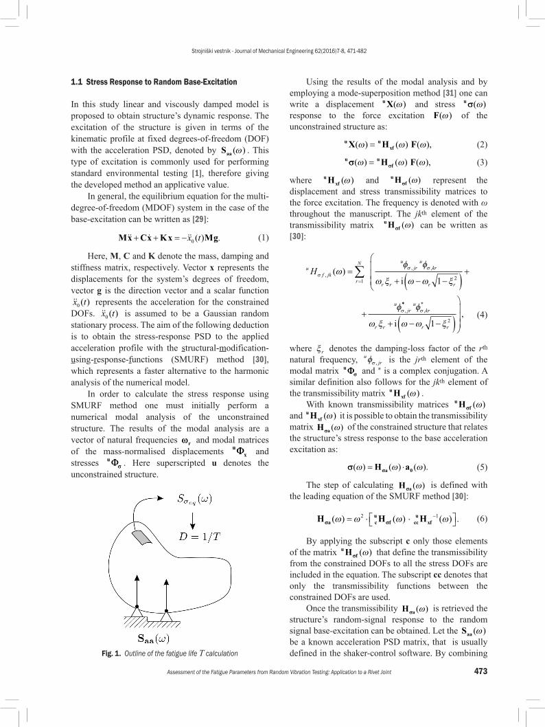
A novel method of fatigue-parameter assessment from a random-signal base-excitation testing can be divided into three main steps. Firstly, the power spectral density (PSD) of the structure’s stress response to the random-signal base-excitation is obtained. Secondly, the structure’s stress response is introduced into the proposed fatigue-life estimation method (Fig. 1). Lastly, by associating the experimentally obtained specimens’s fatigue lives with the numerical fatigue-life estimation the representative values of fatigue strength and fatigue exponent are obtained for the set of tested specimens. This section provides the underlying theoretical background of the new fatigue-parameter assessment method.
Strojniški vestnik - Journal of Mechanical Engineering 62(2016)7-8, 471-482
473Assessment of the Fatigue Parameters from Random Vibration Testing: Application to a Rivet Joint
1.1 Stress Response to Random Base-Excitation
In this study linear and viscously damped model is proposed to obtain structure’s dynamic response. The excitation of the structure is given in terms of the kinematic profile at fixed degrees-of-freedom (DOF) with the acceleration PSD, denoted by Saa ( )ω . This type of excitation is commonly used for performing standard environmental testing [1], therefore giving the developed method an applicative value.
In general, the equilibrium equation for the multi-degree-of-freedom (MDOF) system in the case of the base-excitation can be written as [29]:
Mx Cx Kx Mg + + = −x t0 ( ) . (1)
Here, M, C and K denote the mass, damping and stiffness matrix, respectively. Vector x represents the displacements for the system’s degrees of freedom, vector g is the direction vector and a scalar function x t0 ( ) represents the acceleration for the constrained DOFs. x t0 ( ) is assumed to be a Gaussian random stationary process. The aim of the following deduction is to obtain the stress-response PSD to the applied acceleration profile with the structural-modification-using-response-functions (SMURF) method [30], which represents a faster alternative to the harmonic analysis of the numerical model.
In order to calculate the stress response using SMURF method one must initially perform a numerical modal analysis of the unconstrained structure. The results of the modal analysis are a vector of natural frequencies ωωr and modal matrices of the mass-normalised displacements u
xΦΦ and stresses uΦΦσσ . Here superscripted u denotes the unconstrained structure.
Fig. 1. Outline of the fatigue life T calculation
Using the results of the modal analysis and by employing a mode-superposition method [31] one can write a displacement uX( )ω and stress uσσ( )ω response to the force excitation F( )ω of the unconstrained structure as:
u uxfX H F( ) ( ) ( ),ω ω ω= (2)
u ufH Fσσ σσ( ) ( ) ( ),ω ω ω= (3)
where uxfH ( )ω and u
fHσσ ( )ω represent the displacement and stress transmissibility matrices to the force excitation. The frequency is denoted with ω throughout the manuscript. The jkth element of the transmissibility matrix u
fHσσ ( )ω can be written as [30]:
uf jk
r
N ujru
kr
r r r r
ujr
Hσσ σ
σ
ωφ φ
ω ξ ω ω ξ
φ
,
, ,
,
( ) =+ − −( )
+
+
=∑1
21i
**
,
*
,
ukr
r r r r
φ
ω ξ ω ω ξσ
+ − −( )
i 1 2
(4)
where ξr denotes the damping-loss factor of the rth natural frequency, u
jrφσ , is the jrth element of the modal matrix uΦΦσσ and * is a complex conjugation. A similar definition also follows for the jkth element of the transmissibility matrix u xfH ( )ω .
With known transmissibility matrices ufHσσ ( )ω
and u xfH ( )ω it is possible to obtain the transmissibility matrix H aσσ ( )ω of the constrained structure that relates the structure’s stress response to the base acceleration excitation as:
σσ σσ( ) ( ) ( ).ω ω ω= ⋅H aa 0 (5)
The step of calculating H aσσ ( )ω is defined with the leading equation of the SMURF method [30]:
H H Ha cu
f ccu
xfσσ σσ( ) ( ) ( ) .ω ω ω ω= ⋅ ⋅ −2 1 (6)
By applying the subscript c only those elements of the matrix u fHσσ ( )ω that define the transmissibility from the constrained DOFs to all the stress DOFs are included in the equation. The subscript cc denotes that only the transmissibility functions between the constrained DOFs are used.
Once the transmissibility H aσσ ( )ω is retrieved the structure’s random-signal response to the random signal base-excitation can be obtained. Let the Saa ( )ω be a known acceleration PSD matrix, that is usually defined in the shaker-control software. By combining
Strojniški vestnik - Journal of Mechanical Engineering 62(2016)7-8, 471-482
474 Česnik, M. – Slavič, J. – Boltežar, M.
Eqs. (5) and (6) the stress-response PSD matrix can be obtained as [32] and [33]:
S H S Ha aa aσσσσ σσ σσ( ) ( ) ( ) ( ) .ω ω ω ω= ⋅ ⋅∗ T (7)
Once the stress-response PSD matrix to the random base-excitation is obtained for an arbitrary point on the structure with Eq. (7), the fatigue analysis passes over from the whole dynamic structure to an individual point on the structure, whose stress state is further analysed. For the case of the planar stress state superscript (p) the stress-response PSD matrix at a single point on the structure has the form:
S pσσσσ( )
, , ,
,( )
( ) ( ) ( )
( )ω
ω ω ω
ωσ σ σ σ σ σ
σ σ σ=
S S S
S Sxx xx xx yy xx xy
yy xx yy ,, ,
, , ,
( ) ( )
( ) ( ) ( )
σ σ σ
σ σ σ σ σ σ
ω ω
ω ω ωyy yy xy
xx xy yy xy xy xy
S
S S S
. (8)
Accordingly, for a three-dimensional stress state the stress-response PSD matrix is of size [6×6] [34].
To perform a fatigue analysis of the multi-axial stress in the frequency domain it is essential to obtain the PSD matrix of an equivalent Von Mises stress [23] and [34] of the whole structure with:
Seqσ ω ω( ) [ ( )].= Trace QSσσσσ (9)
In Eq. (9) Q is a constant matrix, which is for a planar stress state given as:
Q =−
−
1 1 2 0
1 2 1 0
0 0 3
/
/ . (10)
Using this definition, the equivalent Von Mises stress is a stationary zero-mean Gaussian process [23] and [34]; therefore, the existing frequency methods [7] for fatigue-life calculations can be adopted. Before this, some general properties of the equivalent stress-response PSD for an individual point on the dynamic structure need to be defined.
1.1.1 Characteristics of a Stress-Response PSD
Since the damage intensity is calculated with frequency-domain counting methods some characteristics of the stress-response spectrum are given here. The shape of the equivalent stress PSD ( S
eqσ ω( ) , Eq. (9)) can be characterized with a set of spectral moments; for a stationary and a zero mean-valued random process σ eq t( ) the mth moment is defined as [7]:
λ ω ω ωσmm S
eq=
∞
∫0 ( ) .d (11)
From Eq. (11) it is obvious that the presented calculation is fully performed in the frequency domain as frequency ω represents the independent variable. Certain spectral moments of the equivalent stress PSD can be used to describe the key properties of a stress loading in the time domain [7]. The number of zero crossings with a positive slope per unit time is defined with:
νπ
λλ02
0
1
2= . (12)
Additionally, the combination of spectral moments gives a number of bandwidth parameters, generally defined as:
αλλ λm
m
m
=0 2
. (13)
1.2 Stress Response to Random Base-Excitation
When the stress loading within a structure is random, the fatigue life can be estimated in the time or frequency domain [5]. For the case of random base-excitation, the frequency-domain methods are faster and based only on the characteristics of the equivalent stress PSD and on the fatigue properties of the material.
Whether the time- or frequency-domain method is used for the fatigue-life estimation, the general rules for fatigue-damage accumulation hold. The most fundamental principle is Palmgren-Miner’s linear damage-accumulation rule [7]:
D nNi
ii=∑ . (14)
In Eq. (14) D denotes the total fatigue damage; the fatigue failure is recognized when D equals unity. ni denotes the number of cycles at a certain load amplitude and Ni is the total number of cycles of a certain load amplitude that would cause fatigue failure. In order to obtain Ni for an arbitrary load amplitude the material fatigue parameters should be considered, as stated in Basquin’s equation [35]:
σ = −C N b1/ . (15)Here, σ denotes the stress amplitude and N the
number of total cycles to the fatigue failure. Eq. (15) introduces two material parameters; the fatigue
Strojniški vestnik - Journal of Mechanical Engineering 62(2016)7-8, 471-482
475Assessment of the Fatigue Parameters from Random Vibration Testing: Application to a Rivet Joint
strength C and the fatigue exponent b. Introducing Eq. (15) into Eq. (14) the damage intensity can be written as [7]:
D C pbp
ba= − ∞
∫1
2 0πν σ σ σ( ) ,d (16)
where pa ( )σ denotes the amplitude distribution of the load history. From Eq. (16) it is evident that the damage intensity relates directly to the bth moment of the stress-amplitude distribution.
According to Pitoiset and Preumont [34] the equivalent stress can be proposed in Eq. (16). In the time domain the stress distribution pa ( )σ is obtained from the rainflow matrix of the stress history [5]; however, in the frequency-domain method the bth moment of pa ( )σ is calculated with the use of statistical characteristics of the equivalent stress PSD. In this study the Tovo-Benasciutti method [36] is used, as it has been proved to give the most accurate results for a number of different random-load profiles [8]. With the Tovo-Benasciutti method the damage intensity is obtained as:
D B B Dtb tbB
NBtb= + −( )−
( ) .1 2
1
2α α (17)
Here, DNB is the damage intensity for the narrow-band stress profile and Btb is a factor obtained from the bandwidth parameters of the stress PSD:
D C bNB p
b b= ( ) ⋅ +
−α ν λ2 02 12
Γ , (18)
Btb =−−
⋅
+ − + + −( )
( )
( )
. ( ( )) ( ) ,.
α αα
α α α α α αα
1 2
2
2
1 2 1 2
2 11
1 2
1
1 112 1 2e (19)
where α1 and α2 are the bandwidth parameters, defined in Eq. (13).
1.3 Fatigue-Parameter Assessment
The most often used approach for vibration fatigue analysis is firstly to obtain the fatigue parameters on specially prepared samples with classic fatigue-testing machines and later use these fatigue parameters on a numerical model and in equations for the damage intensity. However, when designing a new or modified product, often only the information about the product’s fatigue life during accelerated random-vibration tests or service life is available. If the fatigue parameters could be obtained from accelerated vibration tests with random excitation only, the
classic fatigue testing would become unnecessary. However, for the vibration fatigue testing the classical specimens cannot be used since they don’t exhibit any dynamic response in the shaker’s frequency range. Consequently, an alternative testing specimen with adequate dynamic response needs to be designed. In any case, when predicting the vibration fatigue life the vibration testing is an unavoidable step for two reasons: firstly, to verify the numerical model of the structure and, secondly, to obtain the damping ratios of the structure (damping greatly influences the magnitude of stress PSD and can only be identified experimentally).
In terms of existing procedures for fatigue parameter assessment of welded joints [9] the new method developed in this study can be regarded as notch stress approach, relating the numerically obtained stress concentration at the fatigue zone to the actual fatigue life of specimen. Drawing further parallels to existing studies related to the presented research, Allegri and Zhang [23] applied inverse power law to obtain S-N curve from experimental results of fatigue testing with random loading [37]. However, the experimental data Allegri and Zhang analyzed was obtained by exciting the specimens with random loading in the frequency range, that was significantly below the specimens first natural frequency. Consequently, no structural dynamic amplification was involved in the stress response leading to the fatigue fracture. To the author’s knowledge, the only research dealing with vibration fatigue of rivet joints under random vibration was done by Proso et al. [22] who focused their work on the nonlinear damage accumulation. Compared to the existing studies, the main contribution of the presented research is complete and comprehensive vibration fatigue analysis of randomly excited dynamic structure with complex joint, applied to real experimental data from vibration tests. With it, one can adequately evaluate the vibration testing results and obtain joint fatigue parameters. However, in order to obtain values of fatigue parameters, that can be used in future analyses, the following assumptions were made: linear model of dynamic structure, linear damage accumulation and Gaussian stress load distribution.
In this study a Tovo-Benasciutti frequency-domain counting method (Eq. (17)) is implemented in the process of fatigue-parameter assessment. This enables an accurate estimation of the fatigue parameters in which the fatigue tests with different forms of stress-response PSDs can be evaluated altogether. With this, it is possible to establish or broaden a fatigue-parameter database from different
Strojniški vestnik - Journal of Mechanical Engineering 62(2016)7-8, 471-482
476 Česnik, M. – Slavič, J. – Boltežar, M.
accelerated fatigue tests and to predict the vibration fatigue life of a new product, based on the results of earlier vibration fatigue tests of a different structure made from the same material.
From Eq. (15) which relates the number of cycles N to the stress amplitude σ it is clear that for the case of harmonic load the fatigue parameters b and C directly relate to the slope of the Woehler curve and can easily be obtained with the linear least-squares method [5]. However, when assessing the fatigue parameters with the Tovo-Benasciutti frequency method (Eq. (17)) the damage intensity is not linearly related to different shapes of stress PSD. Therefore the numerical minimization of the sum of the squared differences between the estimated and experimental fatigue lives of the test specimens is used. Different shapes of stress PSD arise due to the uncertainties of riveting process (Sec. 2.1) and scatter of damping ratio between specimens, consequently requiring individualized numerical model for each particular specimen in order to obtain adequate stress concentration values. Here, the function being minimized is written as:
∆T b C T T b Ci
act i est i( , ) log ( ) log ( ( , )) .( ), ,= −∑ 10 10
2 (20)
In Eq. (20) i denotes a single test specimen, Tact is the measured fatigue life of the specimen and Test is the estimated fatigue life of the specimen, based on the numerical model and damage-intensity equation (Eq. (16)). In this study, a simplex algorithm [38] is used for the numerical minimization of ΔT (b, C).
2 EXPERIMENTAL WORK AND NUMERICAL ANALYSIS
In order to show the feasibility of assessing the fatigue parameters with a random base-excitation a blind-hole rivet joint was analyzed both experimentally and numerically. Firstly, a series of experiments with different excitation levels was performed on test specimens with a single blind-hole rivet joint, Fig. 2. Secondly, the individualized numerical model was constructed to obtain a valid stress response for each test specimen. Lastly, the fatigue parameters of the rivet joint were obtained with a numerical minimization of the difference between the actual and calculated vibration fatigue lives.
2.1 Random Vibration Test of a Single Rivet Joint
In engineering practice the blind-hole rivet joints are used for assembling and attaching sheet metal; usually there are several rivet joints in the whole riveted
assembly. From previous testing experience, for the case of a riveted assembly the rivet-joint failure occurs on the edge between the rivet head and the rivet stem, Fig. 3. Here, an isolated single rivet joint is used as a test specimen with the same location of the anticipated fatigue zone, as can be seen from the numerical model in Section 2.2.
Fig. 2. Experiment setup for the fatigue test of a single blind-hole rivet joint
The riveting material is an aluminum alloy A95052 with 2.5 % Mg. The blind hole for the rivet’s installation has a diameter of 5.6 mm, and the total height of the rivet is 11.5 mm. The riveted metal strip is made from stainless steel with dimensions of 2 mm × 20 mm × 60 mm. The weight, bolted to the metal strip, weighs 19.1 g and the distance between the weight’s and rivet’s central axis is 40 mm.
Fig. 3. Cross-section of a rivet joint during riveting process
For each vibration test the rivet joint was produced with a manual riveting tool by pulling the rivet mandrel. The riveting force was monitored
Strojniški vestnik - Journal of Mechanical Engineering 62(2016)7-8, 471-482
477Assessment of the Fatigue Parameters from Random Vibration Testing: Application to a Rivet Joint
during the riveting process; the maximum measured force was 1800 N. The fatigue test of the rivet joint was performed by exciting the experimental setup with a white noise defined in the frequency area of the first natural frequency from 150 Hz to 350 Hz; outside of defined frequency range the excitation was not present. The PSD amplitude of white noise acceleration profile was monitored and held constant through the whole fatigue test of individual specimen. A total of 16 specimens were tested on a LDS V555 electro-dynamical shaker with constant PSD amplitudes at levels from 30 (m/s2)2/Hz to 100 (m/s2)2/Hz. The fatigue crack initiated on the outer radii on the edge between the rivet stem and the rivet head, which then proceeded through to reach the inner radii of the rivet stem, as can be seen in Fig. 4. The results of the fatigue tests are presented in Fig. 5 in terms of a graph relating the acceleration PSD amplitude to the fatigue life.
Fig. 4. Fatigue crack at the rivet-joint
Fig. 5. Experimental fatigue lives for AlMg25 rivet joints
Apart from the experimental results, presented in Fig. 5, it is also necessary to address the uncertainties occurring within the experiment and to appropriately account for them in the numerical evaluation of the experiment. For the proposed experimental setup
the main source of uncertainty presents a process of forming a rivet joint. Here, rivet joint is formed by pulling the rivet mandrel (Fig. 3) through the rivet until the mandrel breaks. When connecting the metal sheet to the base by riveting in the blind hole the pulling length until breaking varied, from 3 mm to 7.5 mm. This alters the geometry and stiffness of the rivet joint, which then changes the initial natural frequency ω01 and the damping ξ01 of the tested specimen. As can be seen from Fig. 6, the initial natural frequencies ranged from 266 Hz to 294 Hz. Furthermore, due to the scatter of the pull length the damping and the stress amplitudes at the fatigue zone between the specimens vary as well. The measured data for all the tested specimens are collected in Table 1. This should be taken into account during the numerical evaluation of the experimental results. In order to obtain accurate material parameters for the rivet joint these uncertainties were considered in the numerical evaluation by building several numerical models with different geometries of deformed rivet and modal damping, to obtain an appropriate stress response for each specimen.
Fig. 6. Frequency shift of the first natural frequency for the 16 tested specimens
Furthermore, during the fatigue test the values of the natural frequencies and the damping ratios change. These changes are a consequence of the growing fatigue crack and can be easily observed from the measurements shown in Figs. 6 and 7. Transmissibility measurements were made with the control and response accelerometer (see Fig. 2) every 20 seconds. By comparing individual frequency shifts (Fig. 6) it is obvious that the natural frequency of the specimens with a shorter fatigue life decreased steadily, as opposed to the specimens with a longer fatigue life, where the decrease of the natural frequency occurred in the last 10 % of the fatigue life. In any case, the natural frequency of the specimens remained within the excitation-frequency band of 150 Hz to 350 Hz;
Strojniški vestnik - Journal of Mechanical Engineering 62(2016)7-8, 471-482
478 Česnik, M. – Slavič, J. – Boltežar, M.
therefore, the excitation in the specimen’s resonant area was ensured throughout the fatigue test.
Fig. 7. Transmissibility during the fatigue testing of specimen V5
2.2 Numerical Evaluation of Experimental Results
As discussed in Sec. 2.1, the specimens have different initial modal properties (natural frequency and damping), which tend to change in different ways during the fatigue test. Additionally, due to the nature of the rivet joint and the growing fatigue crack, the rivet-joint specimens are nonlinear dynamic structures. To accommodate all the stated considerations in the fatigue-parameter assessment a fatigue model should be constructed that:• includes different initial natural frequencies and
damping ratios of the individual test specimen,
• includes and predicts continuous changes of the structure’s modal parameters,
• predicts the response of a nonlinear dynamic structure with increasing nonlinearity.The main aim of this study is to present a feasible
procedure to assess the fatigue parameters from a random base-excitation that can be easily applied to different MDOF structures without extensive analysis of the phenomena that occur during the fatigue process. Therefore, a linear numerical model of a dynamic structure is proposed, whose linear response matches the initial response that was measured for each specimen. The model’s modal parameters are assumed to be constant during the fatigue life. Since the random excitation is broad-band and covering the whole area of the frequency shift, the assumption of a constant natural frequency can be made. Although the damping ratio of the numerical model is constant, a rise of the damping ratio is indirectly included in the final values of the fatigue parameters. The increase of the damping ratio reduces the actual stress response in the fatigue zone. Since the constant damping ratio is included in the numerical model, a more severe stress history is predicted with the numerical model when compared to the actual stress during the fatigue test. By equalizing the fatigue lives of the actual test with a lower stress response with the numerically obtained fatigue lives at a higher stress response (Eq. (20)) a higher value of the assessed fatigue strength is anticipated (usually, the fatigue strength equals the yield strength of the material [5]).
Table 1. Results of rivet-joint fatigue testing and numerical calculation
Specimen Initial f01 [Hz] Initial ξ01 [Hz] PSD amplitude [(m/s2)2/Hz] Measured life [s] Calculated life [s]
V01 286 0.0140 30 7100 10328V02 285 0.0142 30 25260 11119V03 281 0.0177 40 5060 5982V04 266 0.0167 40 5480 2963V05 288 0.0134 50 1580 1790V06 294 0.0139 50 5140 3896V07 280 0.0164 60 1600 982V08 284 0.0200 60 1740 3112V09 279 0.0193 70 820 853V10 285 0.0165 70 800 809V11 266 0.0267 80 540 1092V12 270 0.0254 80 900 1068V13 281 0.0230 90 680 790V14 266 0.0251 90 580 683V15 294 0.0137 100 160 273V16 266 0.0175 100 260 114
Strojniški vestnik - Journal of Mechanical Engineering 62(2016)7-8, 471-482
479Assessment of the Fatigue Parameters from Random Vibration Testing: Application to a Rivet Joint
2.2.1 Numerical Model of a Rivet Joint
In order to include the different initial modal parameters of the tested specimens into the numerical analysis a number of different numerical models with different rivet geometries were designed; the rivet geometry is based on the pull length of the rivet mandrel. A shorter pull length results in a thinner rivet wall and a larger distance between the rivet-base contact and the rivet head, which leads to a lower stiffness of the rivet joint. In contrast, a longer pull length results in a thicker rivet wall and a shorter distance between the rivet-base contact and the rivet head, making the rivet joint stiffer. When calculating the stem-wall thickness the volume of the riveting material in the rivet stem was considered to be constant. In this way the first natural frequencies for the numerical model ranged from 265 Hz to 300 Hz.
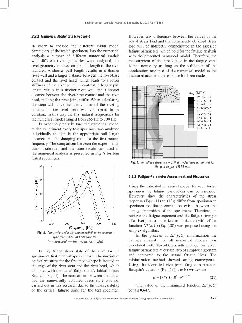
In order to precisely tune the numerical model to the experiment every test specimen was analysed individually to identify the appropriate pull length distance and the damping ratio for the first natural frequency. The comparison between the experimental transmissibilities and the transmissibilities used in the numerical analysis is presented in Fig. 8 for four tested specimens.
Fig. 8. Comparison of initial transmissibilities for selected specimens V02, V03, V06 and V16
(- - - measured, —— from numerical model)
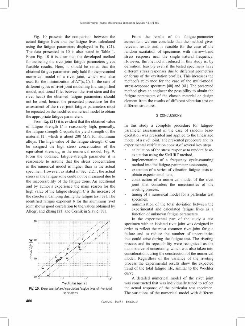
In Fig. 9 the stress state of the rivet for the specimen’s first mode-shape is shown. The maximum equivalent stress for the first mode-shape is located on the edge of the rivet stem and the rivet head, which complies with the actual fatigue-crack initiation (see Sec. 2.1, Fig. 4). The comparison between the actual and the numerically obtained stress state was not carried out in this research due to the inaccessibility of the critical fatigue zone for the test specimen.
However, any differences between the values of the actual stress load and the numerically obtained stress load will be indirectly compensated in the assessed fatigue parameters, which hold for the fatigue analysis with the presented numerical model. Therefore, the measurement of the stress state in the fatigue zone is not necessary as long as the validation of the acceleration response of the numerical model to the measured acceleration response has been made.
Fig. 9. Von Mises stress state of first modeshape at the rivet for the pull length of 5.75 mm
2.2.2 Fatigue-Parameter Assessment and Discussion
Using the validated numerical model for each tested specimen the fatigue parameters can be assessed. However, since the characteristics of the stress response (Eqs. (11) to (13)) differ from specimen to specimen no linear correlation exists between the damage intensities of the specimens. Therefore, to retrieve the fatigue exponent and the fatigue strength of a rivet joint a numerical minimization with of the function ΔT (b, C) (Eq. (20)) was proposed using the simplex algorithm.
In the process of ΔT (b, C) minimization the damage intensity for all numerical models was calculated with Tovo-Benasciutti method for given fatigue parameters at certain step of simplex algorithm and compared to the actual fatigue lives. The minimization method showed strong convergence. Using the identified rivet-joint fatigue parameters Basquin’s equation (Eq. (15)) can be written as:
σ = ⋅ ⋅ −1748 3 106 1 7 52. ./ .N (21)
The value of the minimized function ΔT (b, C) equals 0.647.
Strojniški vestnik - Journal of Mechanical Engineering 62(2016)7-8, 471-482
480 Česnik, M. – Slavič, J. – Boltežar, M.
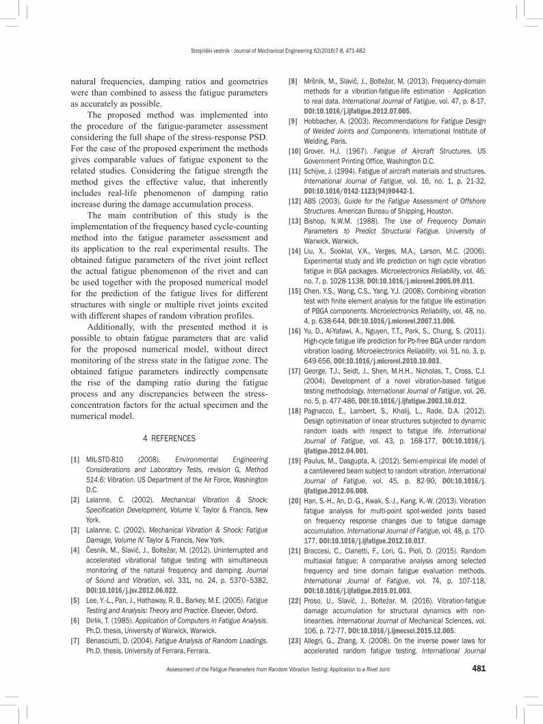
Fig. 10 presents the comparison between the actual fatigue lives and the fatigue lives calculated using the fatigue parameters displayed in Eq. (21). The data presented in 10 is also stated in Table 1. From Fig. 10 it is clear that the developed method for assessing the rivet-joint fatigue parameters gives feasible results. Here, it should be noted that the obtained fatigue parameters only hold for the presented numerical model of a rivet joint, which was also used for the minimization of ΔT (b, C). In the case of different types of rivet-joint modelling (i.e. simplified model, additional fillet between the rivet stem and the rivet head) the obtained fatigue parameters should not be used; hence, the presented procedure for the assessment of the rivet-joint fatigue parameters must be repeated on the modified numerical model to obtain the appropriate fatigue parameters.
From Eq. (21) it is evident that the obtained value of fatigue strength C is reasonably high; generally, the fatigue strength C equals the yield strength of the material [5], which is about 200 MPa for aluminum alloys. The high value of the fatigue strength C can be assigned the high stress concentration of the equivalent stress σeq in the numerical model, Fig. 9. From the obtained fatigue-strength parameter it is reasonable to assume that the stress concentration in the numerical model is higher than in the actual specimen. However, as stated in Sec. 2.2.1, the actual stress in the fatigue zone could not be measured due to the inaccessibility of the fatigue zone. An additional and by author’s experience the main reason for the high value of the fatigue strength C is the increase of the structural damping during the fatigue test [39]. The identified fatigue exponent b for the aluminum rivet joint shows good correlation to the values obtained by Allegri and Zhang [23] and Česnik in Slavič [39].
Fig. 10. Experimental and calculated fatigue lives of rivet-joint specimens
From the results of the fatigue-parameter assessment we can conclude that the method gives relevant results and is feasible for the case of the random excitation of specimens with narrow-band stress response near the single natural frequency. However, the method introduced in this study is, by definition, feasible even if the tested specimens have different stress responses due to different geometries or forms of the excitation profiles. This increases the method’s relevance for the case of the multi-modal stress-response spectrum [40] and [41]. The presented method gives an engineer the possibility to obtain the fatigue parameters of the chosen material or design element from the results of different vibration test on different structures.
3 CONCLUSIONS
In this study a complete procedure for fatigue-parameter assessment in the case of random base-excitation was presented and applied to the linearized model of a rivet joint. The presented procedure and its experimental verification consist of several key steps:• calculation of the stress response to random base-
excitation using the SMURF method,• implementation of a frequency cycle-counting
method into the fatigue-parameter assessment,• execution of a series of vibration fatigue tests to
obtain experimental data,• construction of a numerical model of the rivet
joint that considers the uncertainties of the riveting process,
• tuning of a numerical model for a particular test specimen,
• minimization of the total deviation between the experimental and calculated fatigue lives as a function of unknown fatigue parameters.In the experimental part of the study a test
specimen with an isolated rivet joint was designed in order to reflect the most common rivet-joint fatigue failure and to reduce the number of uncertainties that could arise during the fatigue test. The riveting process and its repeatability were recognized as the main source of uncertainty, which was also taken into consideration during the construction of the numerical model. Regardless of the variance of the riveting process the experimental results show the expected trend of the total fatigue life, similar to the Woehler curve.
A detailed numerical model of the rivet joint was constructed that was individually tuned to reflect the actual response of the particular test specimen. The variations of the numerical model with different
Strojniški vestnik - Journal of Mechanical Engineering 62(2016)7-8, 471-482
481Assessment of the Fatigue Parameters from Random Vibration Testing: Application to a Rivet Joint
natural frequencies, damping ratios and geometries were than combined to assess the fatigue parameters as accurately as possible.
The proposed method was implemented into the procedure of the fatigue-parameter assessment considering the full shape of the stress-response PSD. For the case of the proposed experiment the methods gives comparable values of fatigue exponent to the related studies. Considering the fatigue strength the method gives the effective value, that inherently includes real-life phenomenon of damping ratio increase during the damage accumulation process.
The main contribution of this study is the implementation of the frequency based cycle-counting method into the fatigue parameter assessment and its application to the real experimental results. The obtained fatigue parameters of the rivet joint reflect the actual fatigue phenomenon of the rivet and can be used together with the proposed numerical model for the prediction of the fatigue lives for different structures with single or multiple rivet joints excited with different shapes of random vibration profiles.
Additionally, with the presented method it is possible to obtain fatigue parameters that are valid for the proposed numerical model, without direct monitoring of the stress state in the fatigue zone. The obtained fatigue parameters indirectly compensate the rise of the damping ratio during the fatigue process and any discrepancies between the stress-concentration factors for the actual specimen and the numerical model.
4 REFERENCES
[1] MIL-STD-810 (2008). Environmental Engineering Considerations and Laboratory Tests, revision G, Method 514.6: Vibration. US Department of the Air Force, Washington D.C.
[2] Lalanne, C. (2002). Mechanical Vibration & Shock: Specification Development, Volume V. Taylor & Francis, New York.
[3] Lalanne, C. (2002). Mechanical Vibration & Shock: Fatigue Damage, Volume IV. Taylor & Francis, New York.
[4] Česnik, M., Slavič, J., Boltežar, M. (2012). Uninterrupted and accelerated vibrational fatigue testing with simultaneous monitoring of the natural frequency and damping. Journal of Sound and Vibration, vol. 331, no. 24, p. 5370–5382, DOI:10.1016/j.jsv.2012.06.022.
[5] Lee, Y.-L., Pan, J., Hathaway, R. B., Barkey, M.E. (2005). Fatigue Testing and Analysis: Theory and Practice. Elsevier, Oxford.
[6] Dirlik, T. (1985). Application of Computers in Fatigue Analysis. Ph.D. thesis, University of Warwick, Warwick.
[7] Benasciutti, D. (2004). Fatigue Analysis of Random Loadings. Ph.D. thesis, University of Ferrara, Ferrara.
[8] Mršnik, M., Slavič, J., Boltežar, M. (2013). Frequency-domain methods for a vibration-fatigue-life estimation - Application to real data. International Journal of Fatigue, vol. 47, p. 8-17, DOI:10.1016/j.ijfatigue.2012.07.005.
[9] Hobbacher, A. (2003). Recommendations for Fatigue Design of Welded Joints and Components. International Institute of Welding, Paris.
[10] Grover, H.J. (1967). Fatigue of Aircraft Structures. US Government Printing Office, Washington D.C.
[11] Schijve, J. (1994). Fatigue of aircraft materials and structures. International Journal of Fatigue, vol. 16, no. 1, p. 21-32, DOI:10.1016/0142-1123(94)90442-1.
[12] ABS (2003). Guide for the Fatigue Assessment of Offshore Structures. American Bureau of Shipping, Houston.
[13] Bishop, N.W.M. (1988). The Use of Frequency Domain Parameters to Predict Structural Fatigue. University of Warwick, Warwick.
[14] Liu, X., Sooklal, V.K., Verges, M.A., Larson, M.C. (2006). Experimental study and life prediction on high cycle vibration fatigue in BGA packages. Microelectronics Reliability, vol. 46, no. 7, p. 1028-1138, DOI:10.1016/j.microrel.2005.09.011.
[15] Chen, Y.S., Wang, C.S., Yang, Y.J. (2008). Combining vibration test with finite element analysis for the fatigue life estimation of PBGA components. Microelectronics Reliability, vol. 48, no. 4, p. 638-644, DOI:10.1016/j.microrel.2007.11.006.
[16] Yu, D., Al-Yafawi, A., Nguyen, T.T., Park, S., Chung, S. (2011). High-cycle fatigue life prediction for Pb-free BGA under random vibration loading. Microelectronics Reliability, vol. 51, no. 3, p. 649-656, DOI:10.1016/j.microrel.2010.10.003.
[17] George, T.J., Seidt, J., Shen, M.H.H., Nicholas, T., Cross, C.J. (2004). Development of a novel vibration-based fatigue testing methodology. International Journal of Fatigue, vol. 26, no. 5, p. 477-486, DOI:10.1016/j.ijfatigue.2003.10.012.
[18] Pagnacco, E., Lambert, S., Khalij, L., Rade, D.A. (2012). Design optimisation of linear structures subjected to dynamic random loads with respect to fatigue life. International Journal of Fatigue, vol. 43, p. 168-177, DOI:10.1016/j.ijfatigue.2012.04.001.
[19] Paulus, M., Dasgupta, A. (2012). Semi-empirical life model of a cantilevered beam subject to random vibration. International Journal of Fatigue, vol. 45, p. 82-90, DOI:10.1016/j.ijfatigue.2012.06.008.
[20] Han, S.-H., An, D.-G., Kwak, S.-J., Kang, K.-W. (2013). Vibration fatigue analysis for multi-point spot-welded joints based on frequency response changes due to fatigue damage accumulation. International Journal of Fatigue, vol. 48, p. 170-177, DOI:10.1016/j.ijfatigue.2012.10.017.
[21] Braccesi, C., Cianetti, F., Lori, G., Pioli, D. (2015). Random multiaxial fatigue: A comparative analysis among selected frequency and time domain fatigue evaluation methods. International Journal of Fatigue, vol. 74, p. 107-118, DOI:10.1016/j.ijfatigue.2015.01.003.
[22] Proso, U., Slavič, J., Boltežar, M. (2016). Vibration-fatigue damage accumulation for structural dynamics with non-linearities. International Journal of Mechanical Sciences, vol. 106, p. 72-77, DOI:10.1016/j.ijmecsci.2015.12.005.
[23] Allegri, G., Zhang, X. (2008). On the inverse power laws for accelerated random fatigue testing. International Journal
Strojniški vestnik - Journal of Mechanical Engineering 62(2016)7-8, 471-482
482 Česnik, M. – Slavič, J. – Boltežar, M.
of Fatigue, vol. 30, no. 6, p. 967-977, DOI:10.1016/j.ijfatigue.2007.08.023.
[24] Skorupa, M., Skorupa, A., Machniewicz, T., Korbel, A. (2010). Effect of production variables on the fatigue behaviour of riveted lap joints. International Journal of Fatigue, vol. 32, no. 7, p. 996-1003, DOI:10.1016/j.ijfatigue.2009.11.007.
[25] Skorupa, A., Skorupa, M., Machniewicz, T., Korbel, A. (2014). Fatigue crack location and fatigue life for riveted lap joints in aircraft fuselage. International Journal of Fatigue, vol. 58, p. 209-217, DOI:10.1016/j.ijfatigue.2013.01.014.
[26] Huang, W., Wang, T.-J., Garbatov, Y., Guedes Soares, C. (2012). Fatigue reliability assessment of riveted lap joint of aircraft structures. International Journal of Fatigue, vol. 43, p. 54-61, DOI:10.1016/j.ijfatigue.2012.02.005.
[27] Sun, X., Stephens, E.V., Khaleel, M.A. (2007). Fatigue behaviors of self-piercing rivets joining similar and dissimilar sheet metals. International Journal of Fatigue, vol. 29, no. 2, p. 370-386, DOI:10.1016/j.ijfatigue.2006.02.054.
[28] Fu, M., Mallick, P.K. (2003). Fatigue of self-piercing riveted joints in aluminum alloy 6111. International Journal of Fatigue, vol. 25, no. 3, p. 183-189, DOI:10.1016/S0142-1123(02)00115-9.
[29] Ewins, D.J. (2000) Modal Testing: Theory, Practice and Application. ResearchStudies Press Ltd., Baldock.
[30] Česnik, M., Slavič, J., Čermelj, P., Boltežar, M. (2013). Frequency-based structural modification for the case of base excitation. Journal of Sound and Vibration, vol. 332, no. 20, p. 5029-5039, DOI:10.1016/j.jsv.2013.04.038.
[31] Maia, N.M.M., Silva, J.M.M. (1997). Theoretical and Experimental Modal Analysis. Research Studies Press Ltd., Baldock.
[32] Newland, D.E. (1984). Random Vibration and Spectral Analysis. Longman Scientific & Technical, Essex.
[33] Bonte, M., de Boer, A., Liebregts, R. (2004). Prediction of mechanical fatigue caused by multiple random excitations. Proceedings of International Conference on Noise and Vibration Engineering, p. 697-708.
[34] Pitoiset, X., Preumont, A. (2000). Spectral methods for multiaxial random fatigue analysis of metallic structures. International Journal of Fatigue, vol. 22, no. 7, p. 541-550, DOI:10.1016/S0142-1123(00)00038-4.
[35] Basquin, O.H. (1910). The exponential law of endurance tests. Proceedings of American Society of Testing Materials, vol. 10, p. 625-630.
[36] Benasciutti, D., Tovo, R. (2005). Spectral methods for lifetime prediction under wideband stationary random processes. International Journal of Fatigue, vol. 27, no. 8, p. 867-877, DOI:10.1016/j.ijfatigue.2004.10.007.
[37] Clevenson, S.A., Steiner, R. (1967). Fatigue life under random loading for several power spectral shapes, NASA-TR-266, NASA Langley Research Center, Hampton.
[38] Nash, S.G. (1990). A History of Scientific Computing. ACM, New York.
[39] Česnik, M., Slavič, J. (2014). Vibrational fatigue and structural dynamics for harmonic and random loads. Strojniški vestnik - Journal of Mechanical Engineering, vol. 60, no. 5, p. 339-348, DOI:10.5545/sv-jme.2014.1831.
[40] Low, W.M. (2010). A method for accurate estimation of the fatigue damage induced by bimodal processes. Probabilistic Engineering Mechanics, vol. 25, no. 1, p. 75-85, DOI:10.1016/j.probengmech.2009.08.001.
[41] Gao, Z., Moan, T.M. (2008). Frequency-domain fatigue analysis of wide-band stationary Gaussian processes using a trimodal spectral formulation. International Journal of Fatigue, vol. 30, no. 10-11, p. 1944-1955, DOI:10.1016/j.ijfatigue.2008.01.008.