assertion based verification of amba-ahb using system verilog · sertion based system verilog...
TRANSCRIPT
ISSN No: 2348-4845
Volume No: 2 (2015), Issue No: 7 (July) July 2015 www.ijmetmr.com Page 605
International Journal & Magazine of Engineering, Technology, Management and Research
A Peer Reviewed Open Access International Journal
oCycle accuracy checks.oHorizontal Coverage.
•Test-Bench Enhancements
oUse of Assertions.
oUse of Verification Metrics to check completeness.
oIndustry Standard Methodology.
•Simple and Robust Bus Architecture
oAHB - Advanced High Performance Bus
Assertion-based verification (ABV) is a methodology in which designers use assertions to capture specific de-sign intent and, either through simulation, formal veri-fication, or emulation of these assertions, verify that the design correctly implements that intent. Assertion-based verification (ABV) is a technique that aims to speed one of the most rapidly expanding parts of the design flow. It can also be used in simulation, emula-tion and silicon debug.Research has suggested that verification can take up 70% of the time and cost of a full design cycle and that, within that, functional veri-fication can take up more than half of the verification time. A number of studies have concluded the use of ABV reduces functional verification dramatically com-pared with traditional methods.
In assertion-based verification, RTL assertions are used to capture design intent in a verifiable form as the de-sign is created, providing portable monitors that check for correct behavior. During simulation, assertions improve observability coverage, making the source of an error evident. Simulation debug time is greatly reduced. As targets for formal verification, assertions improve controllability coverage.
Abstract:
Writing assertions concurrently with the RTL design and keeping these assertions closely tied to the RTL code has been found to bring significant benefits in both the design and verification processes for digital hardware. The primary benefit is that assertions help to detect more functional bugs, detect them earlier in the process and detect them closer to their original cause. A secondary benefit is that the very act of formulating and writing assertions can give the designer a better understanding of the design, and hence uncover bugs in the specification or else avoid introducing bugs into the design in the first place. This paper describes as-sertion based system Verilog verification environment with a robust and widely used AMBA AHB bus protocol master-slave architecture.
Keywords:
AMBA, AXI, Verification, System Verilog, Coverage Driven Verification, Functional Verification, Assertion, AHB, Functional Coverage.
1) Introduction:
Assertions bring the possibility of increased metrica-tion to the verification process. Assertions directly in-crease observability of the state of the design during verification. By measuring and controlling the density of assertions and logging assertion passes as well as failures, it is possible to bring some science to the task of knowing when functional verification is complete. This approach has following advantages.
•Tracks the behavioral aspects of the design under verification.
N.KarthikM.Tech VLSI,
CMR Institute of Technology,Kandlakoya Village, Medchal Road,
Hyderabad, Telangana 501401.
M.Gurunadha BabuProfessor & HOD,
CMR Institute of Technology,Kandlakoya Village, Medchal Road,
Hyderabad, Telangana 501401.
Ms. Muni Praveena Rela Associate Professor,
CMR Institute of Technology,Kandlakoya Village, Medchal Road,
Hyderabad, Telangana 501401.
Assertion Based Verification of AMBA-AHB Using System Verilog
ISSN No: 2348-4845
Volume No: 2 (2015), Issue No: 7 (July) July 2015 www.ijmetmr.com Page 606
International Journal & Magazine of Engineering, Technology, Management and Research
A Peer Reviewed Open Access International Journal
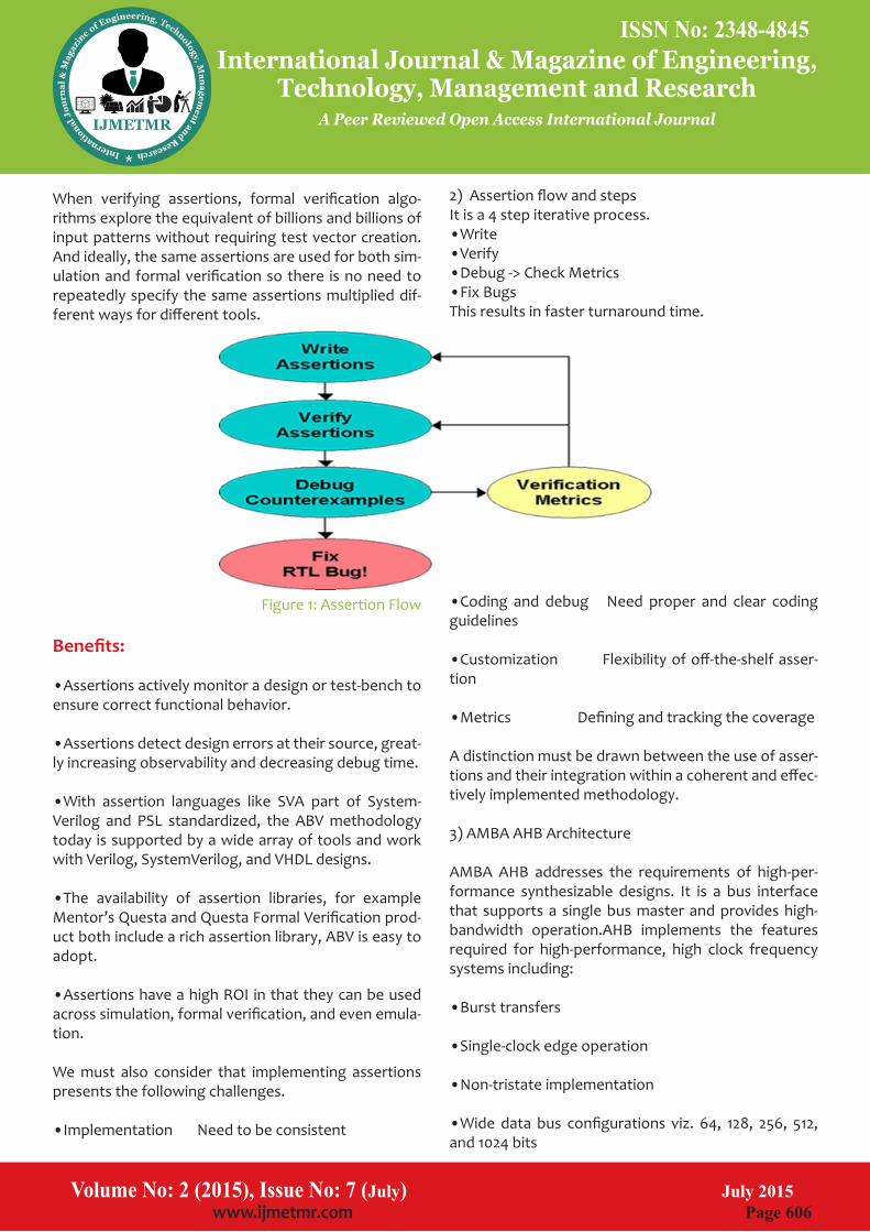
2) Assertion flow and steps It is a 4 step iterative process.•Write•Verify•Debug -> Check Metrics•Fix BugsThis results in faster turnaround time.
•Coding and debug Need proper and clear coding guidelines
•Customization Flexibility of off-the-shelf asser-tion
•Metrics Defining and tracking the coverage
A distinction must be drawn between the use of asser-tions and their integration within a coherent and effec-tively implemented methodology.
3) AMBA AHB Architecture
AMBA AHB addresses the requirements of high-per-formance synthesizable designs. It is a bus interface that supports a single bus master and provides high-bandwidth operation.AHB implements the features required for high-performance, high clock frequency systems including:
•Burst transfers
•Single-clock edge operation
•Non-tristate implementation
•Wide data bus configurations viz. 64, 128, 256, 512, and 1024 bits
When verifying assertions, formal verification algo-rithms explore the equivalent of billions and billions of input patterns without requiring test vector creation. And ideally, the same assertions are used for both sim-ulation and formal verification so there is no need to repeatedly specify the same assertions multiplied dif-ferent ways for different tools.
Figure 1: Assertion Flow
Benefits:
•Assertions actively monitor a design or test-bench to ensure correct functional behavior.
•Assertions detect design errors at their source, great-ly increasing observability and decreasing debug time.
•With assertion languages like SVA part of System-Verilog and PSL standardized, the ABV methodology today is supported by a wide array of tools and work with Verilog, SystemVerilog, and VHDL designs.
•The availability of assertion libraries, for example Mentor’s Questa and Questa Formal Verification prod-uct both include a rich assertion library, ABV is easy to adopt.
•Assertions have a high ROI in that they can be used across simulation, formal verification, and even emula-tion.
We must also consider that implementing assertions presents the following challenges.
•Implementation Need to be consistent
ISSN No: 2348-4845 ISSN No: 2348-4845
Volume No: 2 (2015), Issue No: 7 (July) July 2015 www.ijmetmr.com Page 607
International Journal & Magazine of Engineering, Technology, Management and Research
A Peer Reviewed Open Access International Journal
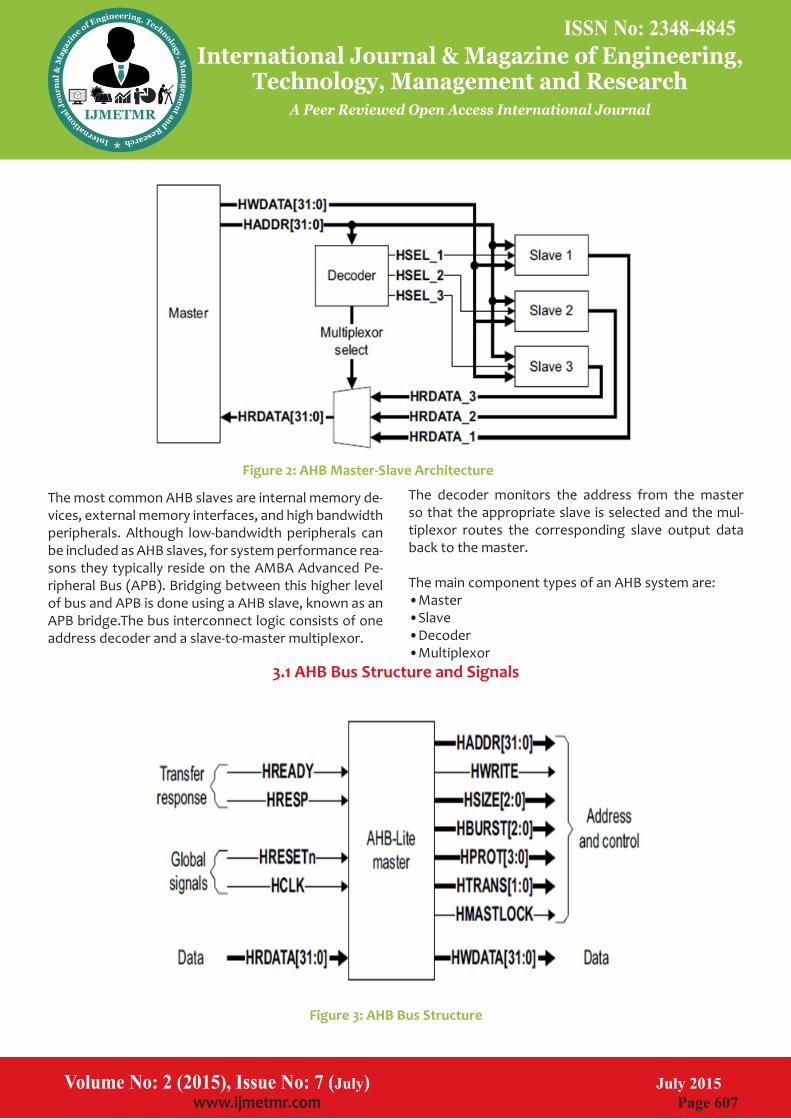
The decoder monitors the address from the master so that the appropriate slave is selected and the mul-tiplexor routes the corresponding slave output data back to the master.
The main component types of an AHB system are:•Master•Slave•Decoder•Multiplexor
The most common AHB slaves are internal memory de-vices, external memory interfaces, and high bandwidth peripherals. Although low-bandwidth peripherals can be included as AHB slaves, for system performance rea-sons they typically reside on the AMBA Advanced Pe-ripheral Bus (APB). Bridging between this higher level of bus and APB is done using a AHB slave, known as an APB bridge.The bus interconnect logic consists of one address decoder and a slave-to-master multiplexor.
Volume No: 2 (2015), Issue No: 7 (July) July 2015 www.ijmetmr.com Page 608
International Journal & Magazine of Engineering, Technology, Management and Research
A Peer Reviewed Open Access International Journal
•HWDATAoThe master output which contains the data it wants to write to an address in a slave. •HRDATAoThe slave output (input to the master) which contains data that is read from a slave.•HSELxoA set of system-specific decoder outputs, generated combinatorially from the decoder’s HADDR input•HRESPoAn output from the slave (input to the master) which indicates whether the transfer was successful •HREADYoThis is an output from each slave which shows when the transfer is completed. •HLOCK/HMASTLOCKo Indicates a locked transfer. •HMASTERoAn arbiter output, in a full AHB system, showing the number of the currently selected master.•HSPLIToAn output from split-capable slaves, to show the ar-biter which masters are currently waiting a response from that
•HCLKo The clock is an input to all elements in an AHB sys-tem and is assumed to come from some external clock generator. •HRESETnoThis active low signal is an input to all elements in AHB. •HADDRoA 32 bit bus, output from the master, which indicates the address to be used for a transfer. •HSIZEoThis master output indicates the size of the read or write transfer to be performed.•HTRANSoAn output from the master (input to slave) which shows the type of transfer to be done. •HWRITEo An output from the master which shows the direc-tion of data transfer.•HBURSToThe master generates this bus to tell the system about the kind of burst it is performing. •HPROTo This allows the master to tell the slave characteristics of the transfer.
Figure 2: AHB Master-Slave Architecture
Figure 3: AHB Bus Structure
3.1 AHB Bus Structure and Signals
ISSN No: 2348-4845 ISSN No: 2348-4845
Volume No: 2 (2015), Issue No: 7 (July) July 2015 www.ijmetmr.com Page 607
International Journal & Magazine of Engineering, Technology, Management and Research
A Peer Reviewed Open Access International Journal
The decoder monitors the address from the master so that the appropriate slave is selected and the mul-tiplexor routes the corresponding slave output data back to the master.
The main component types of an AHB system are:•Master•Slave•Decoder•Multiplexor
The most common AHB slaves are internal memory de-vices, external memory interfaces, and high bandwidth peripherals. Although low-bandwidth peripherals can be included as AHB slaves, for system performance rea-sons they typically reside on the AMBA Advanced Pe-ripheral Bus (APB). Bridging between this higher level of bus and APB is done using a AHB slave, known as an APB bridge.The bus interconnect logic consists of one address decoder and a slave-to-master multiplexor.
Volume No: 2 (2015), Issue No: 7 (July) July 2015 www.ijmetmr.com Page 608
International Journal & Magazine of Engineering, Technology, Management and Research
A Peer Reviewed Open Access International Journal
•HWDATAoThe master output which contains the data it wants to write to an address in a slave. •HRDATAoThe slave output (input to the master) which contains data that is read from a slave.•HSELxoA set of system-specific decoder outputs, generated combinatorially from the decoder’s HADDR input•HRESPoAn output from the slave (input to the master) which indicates whether the transfer was successful •HREADYoThis is an output from each slave which shows when the transfer is completed. •HLOCK/HMASTLOCKo Indicates a locked transfer. •HMASTERoAn arbiter output, in a full AHB system, showing the number of the currently selected master.•HSPLIToAn output from split-capable slaves, to show the ar-biter which masters are currently waiting a response from that
•HCLKo The clock is an input to all elements in an AHB sys-tem and is assumed to come from some external clock generator. •HRESETnoThis active low signal is an input to all elements in AHB. •HADDRoA 32 bit bus, output from the master, which indicates the address to be used for a transfer. •HSIZEoThis master output indicates the size of the read or write transfer to be performed.•HTRANSoAn output from the master (input to slave) which shows the type of transfer to be done. •HWRITEo An output from the master which shows the direc-tion of data transfer.•HBURSToThe master generates this bus to tell the system about the kind of burst it is performing. •HPROTo This allows the master to tell the slave characteristics of the transfer.
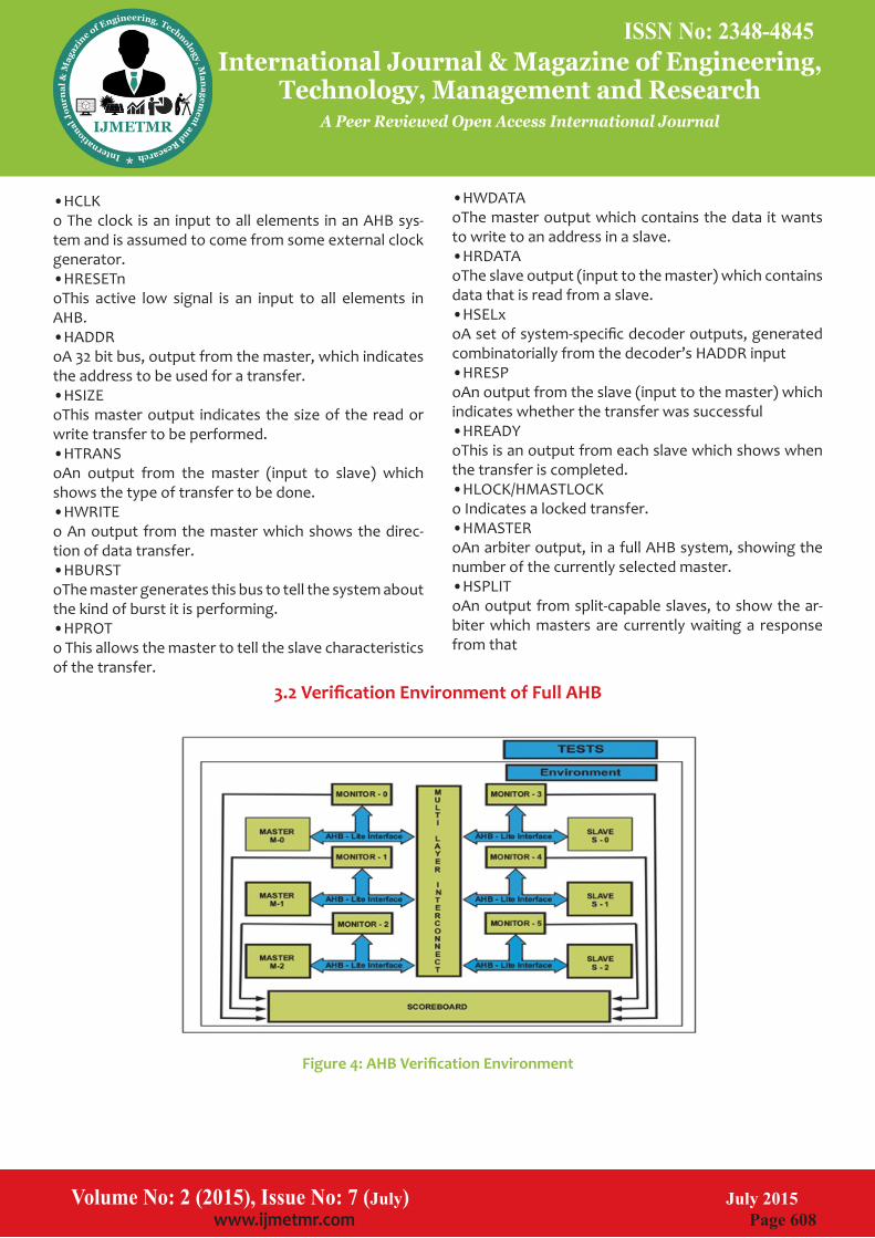
Figure 4: AHB Verification Environment
3.2 Verification Environment of Full AHB
ISSN No: 2348-4845 ISSN No: 2348-4845
Volume No: 2 (2015), Issue No: 7 (July) July 2015 www.ijmetmr.com Page 609
International Journal & Magazine of Engineering, Technology, Management and Research
A Peer Reviewed Open Access International Journal
oThe module which implements all the assertions de-fined in the Assertion Matrix.•AHB ScoreboardoThe class which compares the expected and actual DUT responses and validates the system behavour.•TestsoThe SV class instantiates the verification environment and initiates the stimulus on the design.•SequencesoThe actual stimulus given to the DUT, which wiggles the design pins.
Tools Used:•Modelsim •Questasim
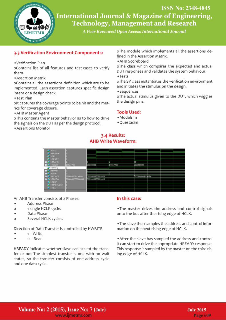
In this case:
•The master drives the address and control signals onto the bus after the rising edge of HCLK.
•The slave then samples the address and control infor-mation on the next rising edge of HCLK.
•After the slave has sampled the address and control it can start to drive the appropriate HREADY response. This response is sampled by the master on the third ris-ing edge of HCLK.
3.3 Verification Environment Components:
•Verification PlanoContains list of all features and test-cases to verify them.•Assertion MatrixoContains all the assertions definition which are to be implemented. Each assertion captures specific design intent or a design check.•Test PlanoIt captures the coverage points to be hit and the met-rics for coverage closure.•AHB Master AgentoThis contains the Master behavior as to how to drive the signals on the DUT as per the design protocol.•Assertions Monitor
An AHB Transfer consists of 2 Phases.• Address Phaseo 1 single HCLK cycle.• Data Phaseo Several HCLK cycles.
Direction of Data Transfer is controlled by HWRITE• 1 -- Write• 0 -- Read
HREADY indicates whether slave can accept the trans-fer or not The simplest transfer is one with no wait states, so the transfer consists of one address cycle and one data cycle.
Volume No: 2 (2015), Issue No: 7 (July) July 2015 www.ijmetmr.com Page 610
International Journal & Magazine of Engineering, Technology, Management and Research
A Peer Reviewed Open Access International Journal
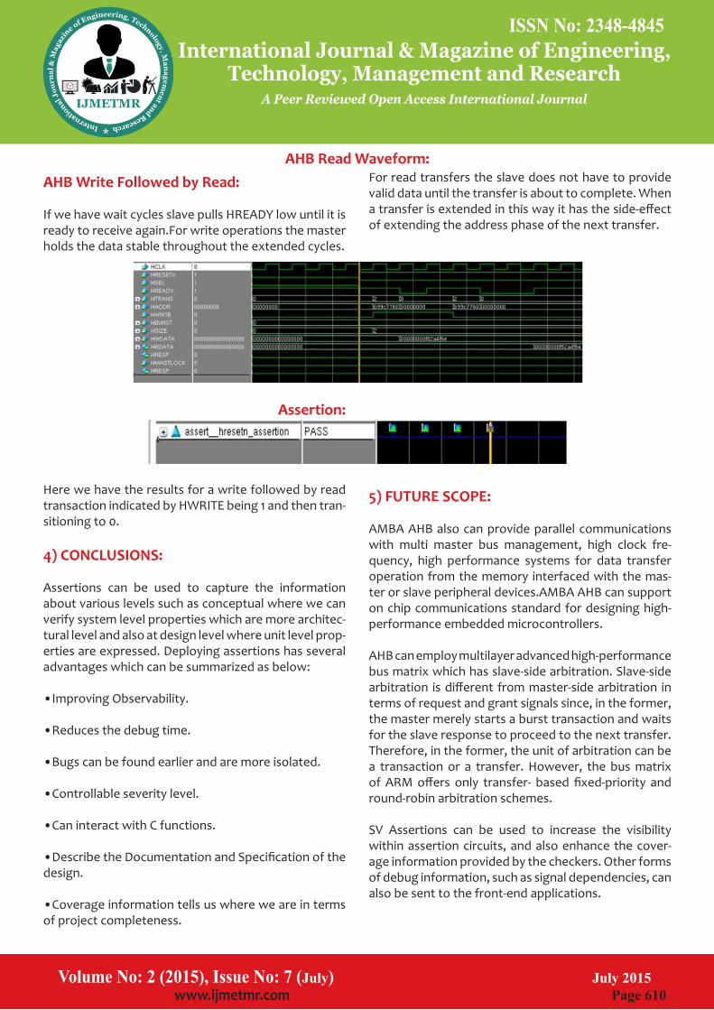
For read transfers the slave does not have to provide valid data until the transfer is about to complete. When a transfer is extended in this way it has the side-effect of extending the address phase of the next transfer.
5) FUTURE SCOPE:
AMBA AHB also can provide parallel communications with multi master bus management, high clock fre-quency, high performance systems for data transfer operation from the memory interfaced with the mas-ter or slave peripheral devices.AMBA AHB can support on chip communications standard for designing high-performance embedded microcontrollers.
AHB can employ multilayer advanced high-performance bus matrix which has slave-side arbitration. Slave-side arbitration is different from master-side arbitration in terms of request and grant signals since, in the former, the master merely starts a burst transaction and waits for the slave response to proceed to the next transfer. Therefore, in the former, the unit of arbitration can be a transaction or a transfer. However, the bus matrix of ARM offers only transfer- based fixed-priority and round-robin arbitration schemes.
SV Assertions can be used to increase the visibility within assertion circuits, and also enhance the cover-age information provided by the checkers. Other forms of debug information, such as signal dependencies, can also be sent to the front-end applications.
AHB Write Followed by Read:
If we have wait cycles slave pulls HREADY low until it is ready to receive again.For write operations the master holds the data stable throughout the extended cycles.
Assertion:
Here we have the results for a write followed by read transaction indicated by HWRITE being 1 and then tran-sitioning to 0.
4) CONCLUSIONS:
Assertions can be used to capture the information about various levels such as conceptual where we can verify system level properties which are more architec-tural level and also at design level where unit level prop-erties are expressed. Deploying assertions has several advantages which can be summarized as below:
•Improving Observability.
•Reduces the debug time.
•Bugs can be found earlier and are more isolated.
•Controllable severity level.
•Can interact with C functions.
•Describe the Documentation and Specification of the design.
•Coverage information tells us where we are in terms of project completeness.
3.4 Results:AHB Write Waveform:
ISSN No: 2348-4845 ISSN No: 2348-4845
Volume No: 2 (2015), Issue No: 7 (July) July 2015 www.ijmetmr.com Page 609
International Journal & Magazine of Engineering, Technology, Management and Research
A Peer Reviewed Open Access International Journal
oThe module which implements all the assertions de-fined in the Assertion Matrix.•AHB ScoreboardoThe class which compares the expected and actual DUT responses and validates the system behavour.•TestsoThe SV class instantiates the verification environment and initiates the stimulus on the design.•SequencesoThe actual stimulus given to the DUT, which wiggles the design pins.
Tools Used:•Modelsim •Questasim
In this case:
•The master drives the address and control signals onto the bus after the rising edge of HCLK.
•The slave then samples the address and control infor-mation on the next rising edge of HCLK.
•After the slave has sampled the address and control it can start to drive the appropriate HREADY response. This response is sampled by the master on the third ris-ing edge of HCLK.
3.3 Verification Environment Components:
•Verification PlanoContains list of all features and test-cases to verify them.•Assertion MatrixoContains all the assertions definition which are to be implemented. Each assertion captures specific design intent or a design check.•Test PlanoIt captures the coverage points to be hit and the met-rics for coverage closure.•AHB Master AgentoThis contains the Master behavior as to how to drive the signals on the DUT as per the design protocol.•Assertions Monitor
An AHB Transfer consists of 2 Phases.• Address Phaseo 1 single HCLK cycle.• Data Phaseo Several HCLK cycles.
Direction of Data Transfer is controlled by HWRITE• 1 -- Write• 0 -- Read
HREADY indicates whether slave can accept the trans-fer or not The simplest transfer is one with no wait states, so the transfer consists of one address cycle and one data cycle.
Volume No: 2 (2015), Issue No: 7 (July) July 2015 www.ijmetmr.com Page 610
International Journal & Magazine of Engineering, Technology, Management and Research
A Peer Reviewed Open Access International Journal
For read transfers the slave does not have to provide valid data until the transfer is about to complete. When a transfer is extended in this way it has the side-effect of extending the address phase of the next transfer.
5) FUTURE SCOPE:
AMBA AHB also can provide parallel communications with multi master bus management, high clock fre-quency, high performance systems for data transfer operation from the memory interfaced with the mas-ter or slave peripheral devices.AMBA AHB can support on chip communications standard for designing high-performance embedded microcontrollers.
AHB can employ multilayer advanced high-performance bus matrix which has slave-side arbitration. Slave-side arbitration is different from master-side arbitration in terms of request and grant signals since, in the former, the master merely starts a burst transaction and waits for the slave response to proceed to the next transfer. Therefore, in the former, the unit of arbitration can be a transaction or a transfer. However, the bus matrix of ARM offers only transfer- based fixed-priority and round-robin arbitration schemes.
SV Assertions can be used to increase the visibility within assertion circuits, and also enhance the cover-age information provided by the checkers. Other forms of debug information, such as signal dependencies, can also be sent to the front-end applications.
AHB Write Followed by Read:
If we have wait cycles slave pulls HREADY low until it is ready to receive again.For write operations the master holds the data stable throughout the extended cycles.
Assertion:
Here we have the results for a write followed by read transaction indicated by HWRITE being 1 and then tran-sitioning to 0.
4) CONCLUSIONS:
Assertions can be used to capture the information about various levels such as conceptual where we can verify system level properties which are more architec-tural level and also at design level where unit level prop-erties are expressed. Deploying assertions has several advantages which can be summarized as below:
•Improving Observability.
•Reduces the debug time.
•Bugs can be found earlier and are more isolated.
•Controllable severity level.
•Can interact with C functions.
•Describe the Documentation and Specification of the design.
•Coverage information tells us where we are in terms of project completeness.
AHB Read Waveform:

ISSN No: 2348-4845 ISSN No: 2348-4845
Volume No: 2 (2015), Issue No: 7 (July) July 2015 www.ijmetmr.com Page 611
International Journal & Magazine of Engineering, Technology, Management and Research
A Peer Reviewed Open Access International Journal
[4] http://www.cadence.com/products/fv/Pages/abv_flow.aspx
[5]http://www.techdesignforums.com/practice/guides/guide-to-assertion-based-verification/
[6] https://verificationacademy.com/courses/assertion-based-verification
[7]http://www.mentor.com/products/fv/methodolo-gies/abv/
6) References:
[1] Assertion-Based Verification using SystemVerilog - Verilab www.verilab.com/files/svug_2007_abv_litter-ick.pdf
[2] SOC Bus Transaction Verification Using AMBA ... - JSTS
[3] www.jsts.org/html/journal/journal_files/.../6/2020_vol2_no2_132.pdf
Volume No: 2 (2015), Issue No: 7 (July) July 2015 www.ijmetmr.com Page 612
International Journal & Magazine of Engineering, Technology, Management and Research
A Peer Reviewed Open Access International Journal