assembly instructions tourmaster side rails - wenger corp tourmaster side rails... · assembly...
TRANSCRIPT
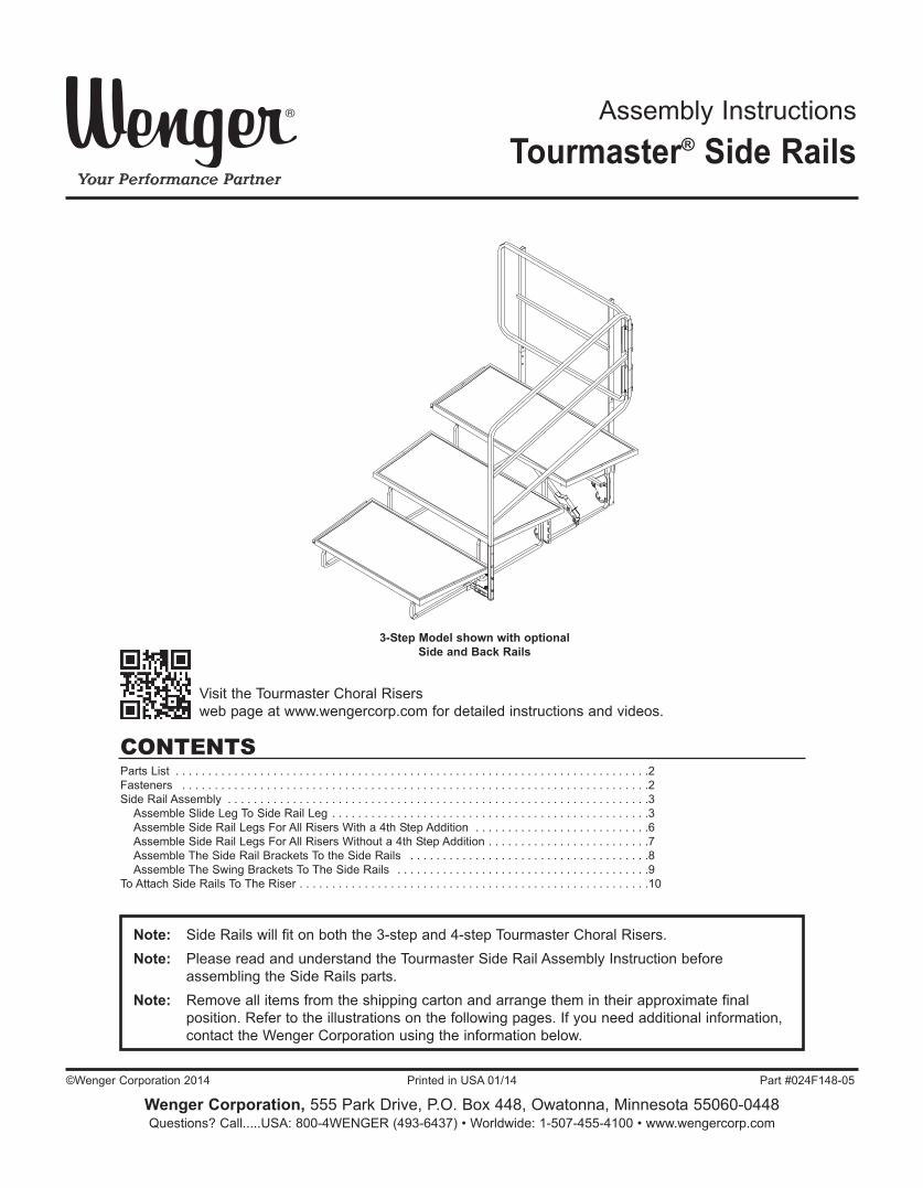
Assembly Instructions
Tourmaster® Side Rails
Parts List . . . . . . . . . . . . . . . . . . . . . . . . . . . . . . . . . . . . . . . . . . . . . . . . . . . . . . . . . . . . . . . . . . . . . . . . .2Fasteners . . . . . . . . . . . . . . . . . . . . . . . . . . . . . . . . . . . . . . . . . . . . . . . . . . . . . . . . . . . . . . . . . . . . . . . .2Side Rail Assembly . . . . . . . . . . . . . . . . . . . . . . . . . . . . . . . . . . . . . . . . . . . . . . . . . . . . . . . . . . . . . . . . .3Assemble Slide Leg To Side Rail Leg . . . . . . . . . . . . . . . . . . . . . . . . . . . . . . . . . . . . . . . . . . . . . . . . .3Assemble Side Rail Legs For All Risers With a 4th Step Addition . . . . . . . . . . . . . . . . . . . . . . . . . . .6Assemble Side Rail Legs For All Risers Without a 4th Step Addition . . . . . . . . . . . . . . . . . . . . . . . . .7Assemble The Side Rail Brackets To the Side Rails . . . . . . . . . . . . . . . . . . . . . . . . . . . . . . . . . . . . .8Assemble The Swing Brackets To The Side Rails . . . . . . . . . . . . . . . . . . . . . . . . . . . . . . . . . . . . . . .9
To Attach Side Rails To The Riser . . . . . . . . . . . . . . . . . . . . . . . . . . . . . . . . . . . . . . . . . . . . . . . . . . . . . .10
Note: Side Rails will fit on both the 3-step and 4-step Tourmaster Choral Risers.Note: Please read and understand the Tourmaster Side Rail Assembly Instruction before
assembling the Side Rails parts.Note: Remove all items from the shipping carton and arrange them in their approximate final
position. Refer to the illustrations on the following pages. If you need additional information, contact the Wenger Corporation using the information below.
3-Step Model shown with optionalSide and Back Rails
CONTENTS
©Wenger Corporation 2014 Printed in USA 01/14 Part #024F148-05
Wenger Corporation, 555 Park Drive, P.O. Box 448, Owatonna, Minnesota 55060-0448Questions? Call.....USA: 800-4WENGER (493-6437) • Worldwide: 1-507-455-4100 • www.wengercorp.com
Visit the Tourmaster Choral Risers web page at www.wengercorp.com for detailed instructions and videos.
2
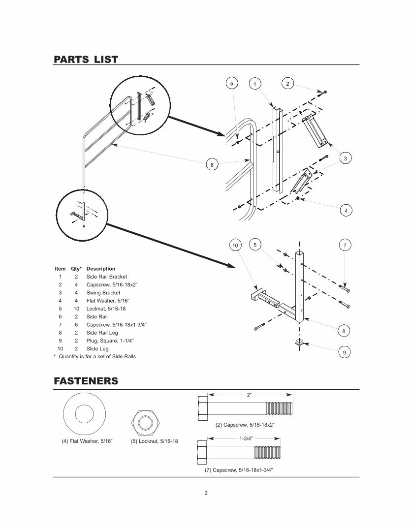
Item Qty* Description1 2 Side Rail Bracket2 4 Capscrew, 5/16-18x2”3 4 Swing Bracket4 4 Flat Washer, 5/16”5 10 Locknut, 5/16-186 2 Side Rail7 6 Capscrew, 5/16-18x1-3/4”8 2 Side Rail Leg9 2 Plug, Square, 1-1/4”10 2 Slide Leg* Quantity is for a set of Side Rails.
PARTS LIST
FASTENERS
(4) Flat Washer, 5/16” (5) Locknut, 5/16-18
(2) Capscrew, 5/16-18x2”
2”
(7) Capscrew, 5/16-18x1-3/4”
1-3/4”
3
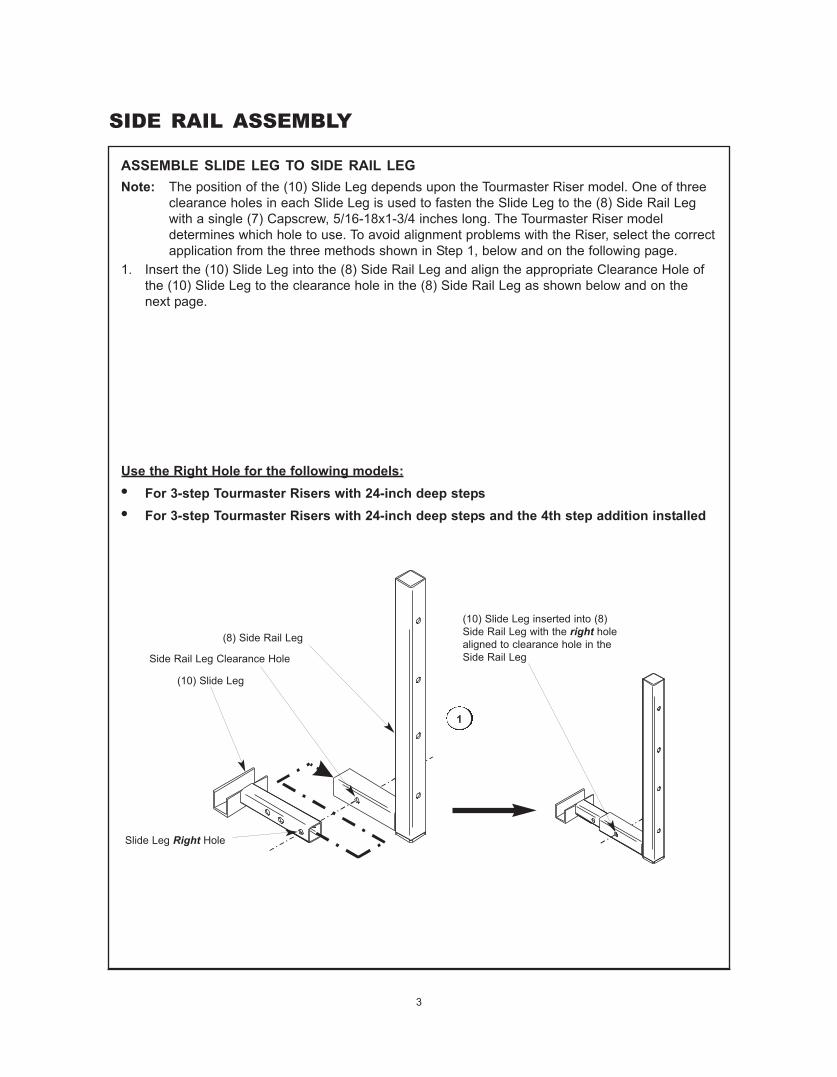
ASSEMBLE SLIDE LEG TO SIDE RAIL LEG
SIDE RAIL ASSEMBLY
Note: The position of the (10) Slide Leg depends upon the Tourmaster Riser model. One of threeclearance holes in each Slide Leg is used to fasten the Slide Leg to the (8) Side Rail Legwith a single (7) Capscrew, 5/16-18x1-3/4 inches long. The Tourmaster Riser modeldetermines which hole to use. To avoid alignment problems with the Riser, select the correctapplication from the three methods shown in Step 1, below and on the following page.
1. Insert the (10) Slide Leg into the (8) Side Rail Leg and align the appropriate Clearance Hole ofthe (10) Slide Leg to the clearance hole in the (8) Side Rail Leg as shown below and on thenext page.
Use the Right Hole for the following models:• For 3-step Tourmaster Risers with 24-inch deep steps• For 3-step Tourmaster Risers with 24-inch deep steps and the 4th step addition installed
1
(10) Slide Leg
Slide Leg Right Hole
(8) Side Rail Leg
Side Rail Leg Clearance Hole
(10) Slide Leg inserted into (8)Side Rail Leg with the right holealigned to clearance hole in theSide Rail Leg
4
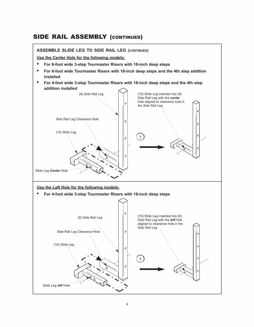
SIDE RAIL ASSEMBLY (CONTINUED)
Slide Leg Center Hole
(8) Side Rail Leg
Side Rail Leg Clearance Hole
1
ASSEMBLE SLIDE LEG TO SIDE RAIL LEG (CONTINUED)
Use the Center Hole for the following models:• For 6-foot wide 3-step Tourmaster Risers with 18-inch deep steps• For 6-foot wide Tourmaster Risers with 18-inch deep steps and the 4th step addition
installed• For 4-foot wide 3-step Tourmaster Risers with 18-inch deep steps and the 4th step
addition installed(10) Slide Leg inserted into (8)Side Rail Leg with the centerhole aligned to clearance hole inthe Side Rail Leg
Use the Left Hole for the following models:• For 4-foot wide 3-step Tourmaster Risers with 18-inch deep steps
(10) Slide Leg
Slide Leg left Hole
(8) Side Rail Leg
Side Rail Leg Clearance Hole
1
(10) Slide Leg inserted into (8)Side Rail Leg with the left holealigned to clearance hole in theSide Rail Leg
(10) Slide Leg
5
SIDE RAIL ASSEMBLY (CONTINUED)
Side Rail Leg Clearance Hole (5) Locknut, 5/16-18
(7) Capscrew, 5/16-18x1-3/4”
(8) Side Rail Leg
(10) Slide Leg
2
3
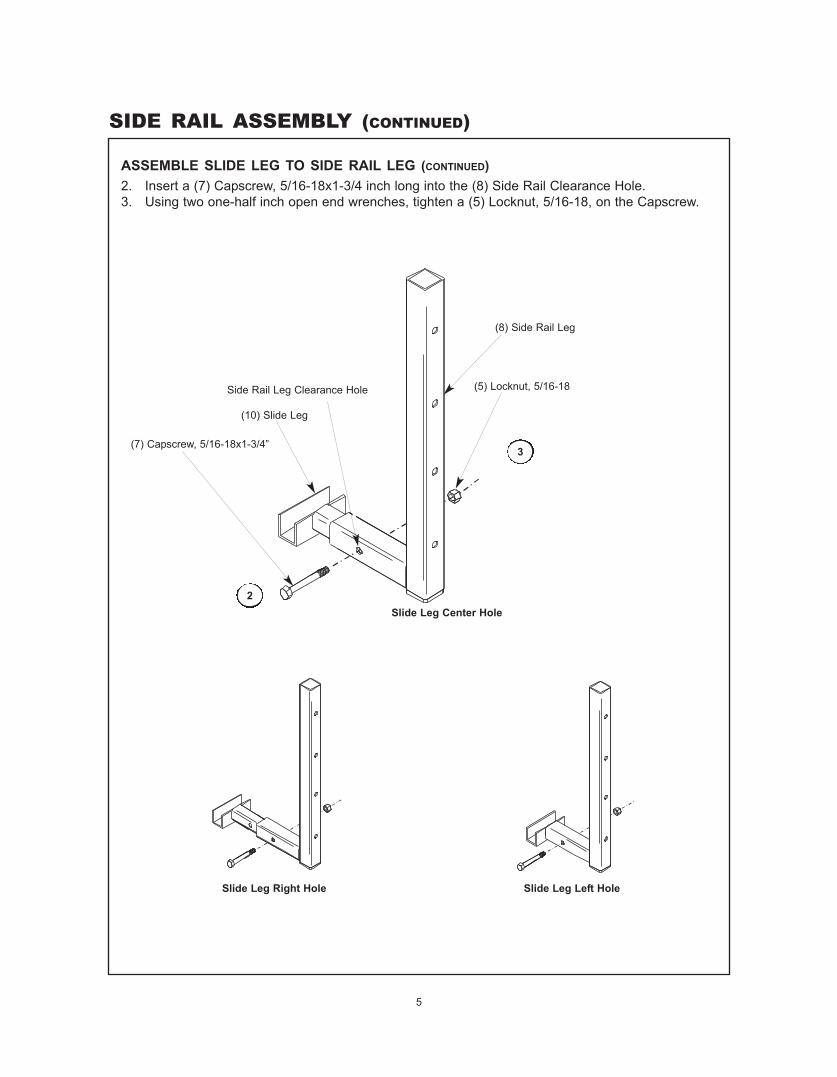
ASSEMBLE SLIDE LEG TO SIDE RAIL LEG (CONTINUED)2. Insert a (7) Capscrew, 5/16-18x1-3/4 inch long into the (8) Side Rail Clearance Hole.3. Using two one-half inch open end wrenches, tighten a (5) Locknut, 5/16-18, on the Capscrew.
Slide Leg Center Hole
Slide Leg Left HoleSlide Leg Right Hole
6
SIDE RAIL ASSEMBLY (CONTINUED)
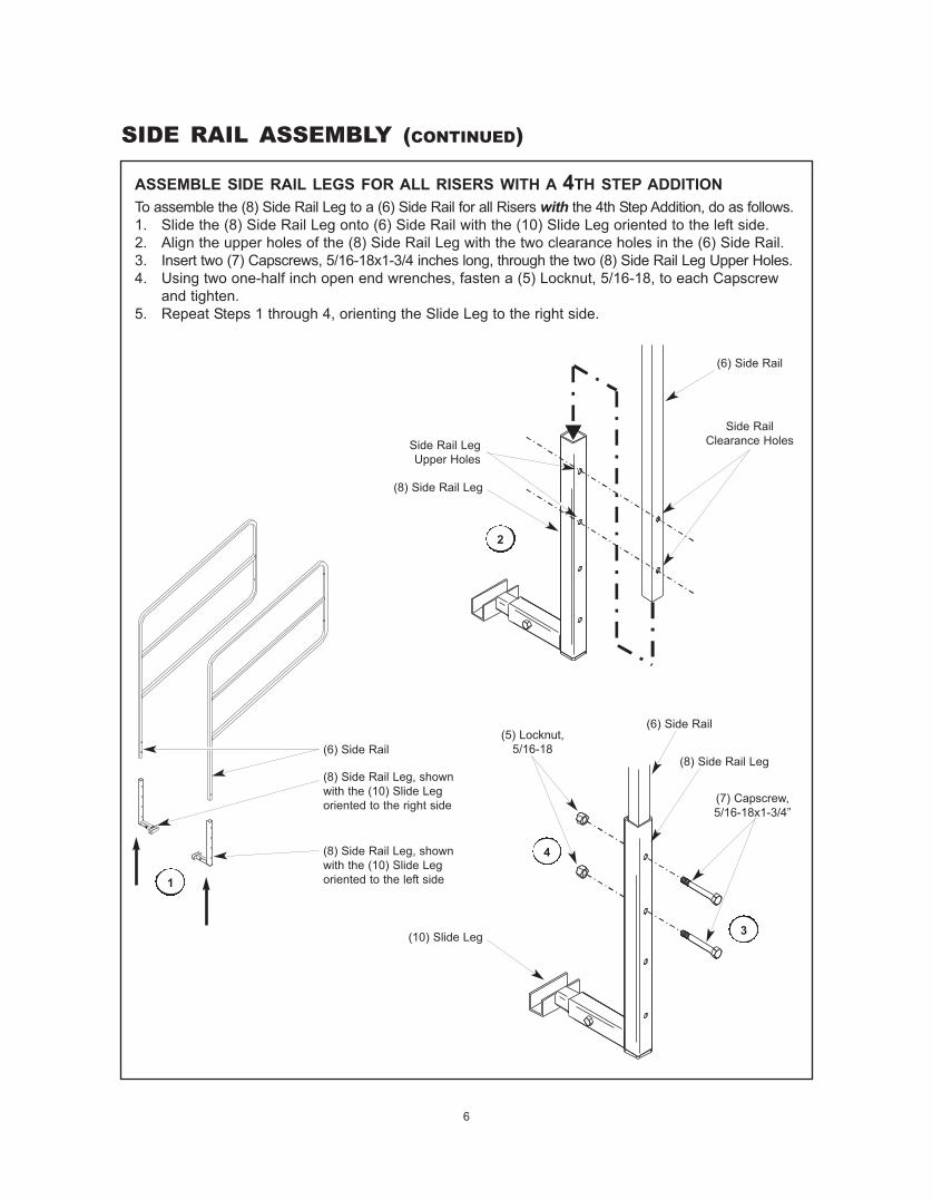
ASSEMBLE SIDE RAIL LEGS FOR ALL RISERS WITH A 4TH STEP ADDITIONTo assemble the (8) Side Rail Leg to a (6) Side Rail for all Risers with the 4th Step Addition, do as follows.1. Slide the (8) Side Rail Leg onto (6) Side Rail with the (10) Slide Leg oriented to the left side. 2. Align the upper holes of the (8) Side Rail Leg with the two clearance holes in the (6) Side Rail.3. Insert two (7) Capscrews, 5/16-18x1-3/4 inches long, through the two (8) Side Rail Leg Upper Holes.4. Using two one-half inch open end wrenches, fasten a (5) Locknut, 5/16-18, to each Capscrew
and tighten.5. Repeat Steps 1 through 4, orienting the Slide Leg to the right side.
(6) Side Rail
(8) Side Rail Leg, shownwith the (10) Slide Legoriented to the right side
(8) Side Rail Leg, shownwith the (10) Slide Legoriented to the left side1
Side Rail LegUpper Holes
Side RailClearance Holes
(5) Locknut,5/16-18
(7) Capscrew,5/16-18x1-3/4”
(6) Side Rail
(8) Side Rail Leg
(10) Slide Leg
2
3
(8) Side Rail Leg
(6) Side Rail
4
7
SIDE RAIL ASSEMBLY (CONTINUED)
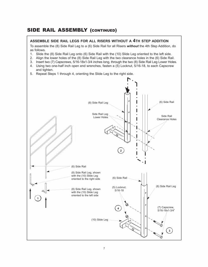
ASSEMBLE SIDE RAIL LEGS FOR ALL RISERS WITHOUT A 4TH STEP ADDITIONTo assemble the (8) Side Rail Leg to a (6) Side Rail for all Risers without the 4th Step Addition, doas follows.1. Slide the (8) Side Rail Leg onto (6) Side Rail with the (10) Slide Leg oriented to the left side.2. Align the lower holes of the (8) Side Rail Leg with the two clearance holes in the (6) Side Rail.3. Insert two (7) Capscrews, 5/16-18x1-3/4 inches long, through the two (8) Side Rail Leg Lower Holes.4. Using two one-half inch open end wrenches, fasten a (5) Locknut, 5/16-18, to each Capscrew
and tighten.5. Repeat Steps 1 through 4, orienting the Slide Leg to the right side.
(6) Side Rail
(8) Side Rail Leg, shownwith the (10) Slide Legoriented to the right side
(8) Side Rail Leg, shownwith the (10) Slide Legoriented to the left side
1
Side Rail LegLower Holes Side Rail
Clearance Holes
2
(8) Side Rail Leg (6) Side Rail
(5) Locknut,5/16-18
(7) Capscrew,5/16-18x1-3/4”
(6) Side Rail
(8) Side Rail Leg
(10) Slide Leg
3
4
8
SIDE RAIL ASSEMBLY (CONTINUED)
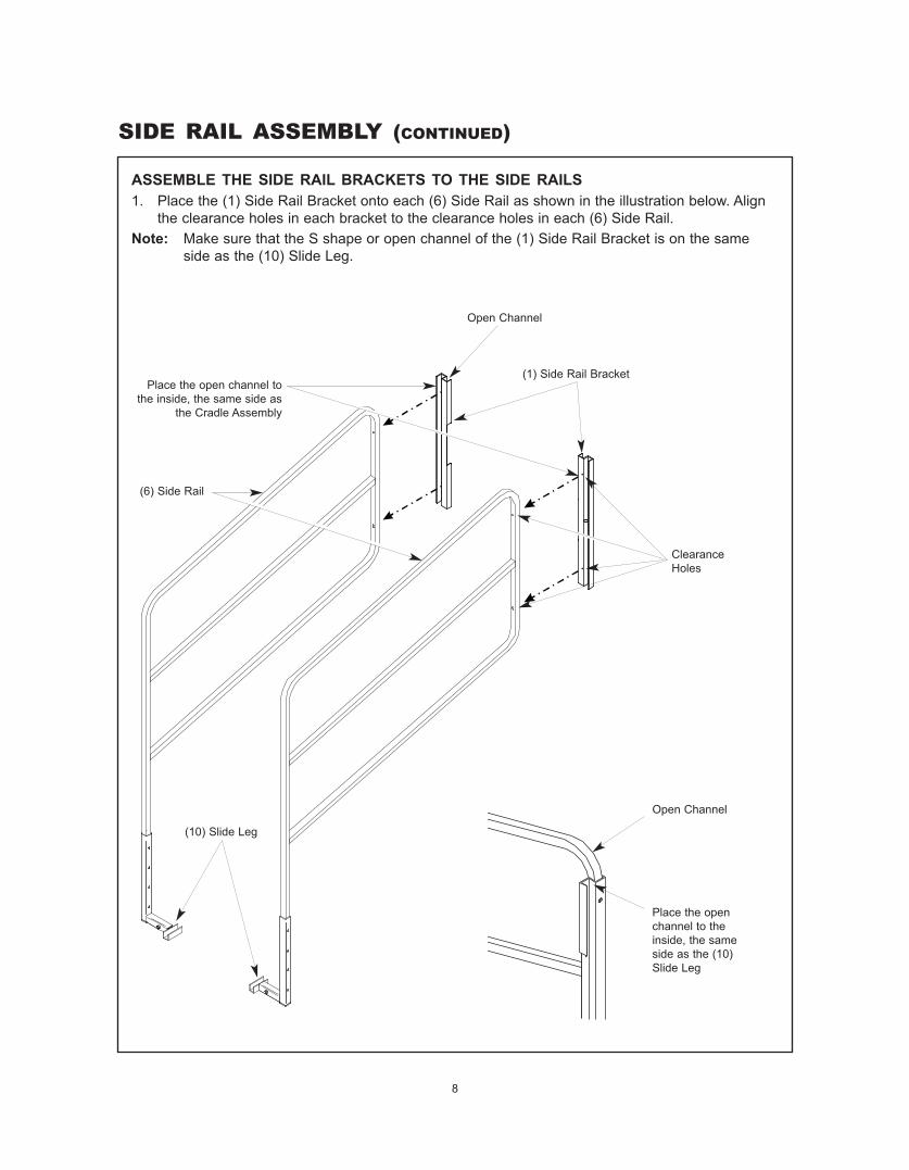
1. Place the (1) Side Rail Bracket onto each (6) Side Rail as shown in the illustration below. Alignthe clearance holes in each bracket to the clearance holes in each (6) Side Rail.
Note: Make sure that the S shape or open channel of the (1) Side Rail Bracket is on the sameside as the (10) Slide Leg.
ASSEMBLE THE SIDE RAIL BRACKETS TO THE SIDE RAILS
(1) Side Rail BracketPlace the open channel to
the inside, the same side asthe Cradle Assembly
ClearanceHoles
Open Channel
(6) Side Rail
Place the openchannel to theinside, the sameside as the (10)Slide Leg
Open Channel
(10) Slide Leg
9
SIDE RAIL ASSEMBLY (CONTINUED)
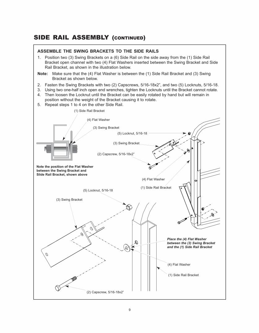
ASSEMBLE THE SWING BRACKETS TO THE SIDE RAILS
(5) Locknut, 5/16-18
(3) Swing Bracket
(2) Capscrew, 5/16-18x2”
(4) Flat Washer
(1) Side Rail Bracket(5) Locknut, 5/16-18
(3) Swing Bracket
(2) Capscrew, 5/16-18x2”
(4) Flat Washer
(1) Side Rail Bracket
Place the (4) Flat Washerbetween the (3) Swing Bracketand the (1) Side Rail Bracket
(4) Flat Washer
(1) Side Rail Bracket
(3) Swing Bracket
Note the position of the Flat Washerbetween the Swing Bracket andSlide Rail Bracket, shown above
1. Position two (3) Swing Brackets on a (6) Side Rail on the side away from the (1) Side RailBracket open channel with two (4) Flat Washers inserted between the Swing Bracket and SideRail Bracket, as shown in the illustration below.
Note: Make sure that the (4) Flat Washer is between the (1) Side Rail Bracket and (3) SwingBracket as shown below.
2. Fasten the Swing Brackets with two (2) Capscrews, 5/16-18x2”, and two (5) Locknuts, 5/16-18.3. Using two one-half inch open end wrenches, tighten the Locknuts until the Bracket cannot rotate.4. Then loosen the Locknut until the Bracket can be easily rotated by hand but will remain in
position without the weight of the Bracket causing it to rotate.5. Repeat steps 1 to 4 on the other Side Rail.
10
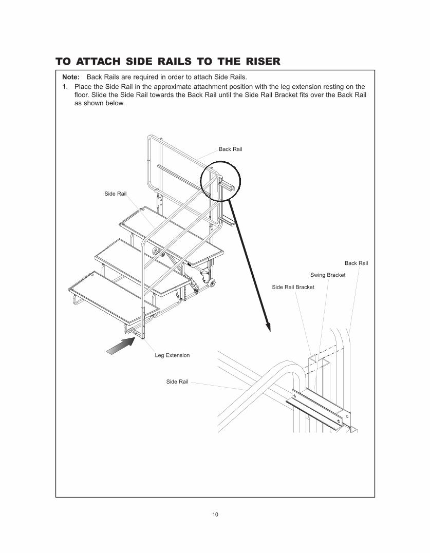
TO ATTACH SIDE RAILS TO THE RISERNote: Back Rails are required in order to attach Side Rails.1. Place the Side Rail in the approximate attachment position with the leg extension resting on the
floor. Slide the Side Rail towards the Back Rail until the Side Rail Bracket fits over the Back Railas shown below.
Back Rail
Side Rail
Side Rail
Back Rail
Side Rail Bracket
Swing Bracket
Leg Extension
11
TO ATTACH SIDE RAILS TO THE RISER (CONTINUED)
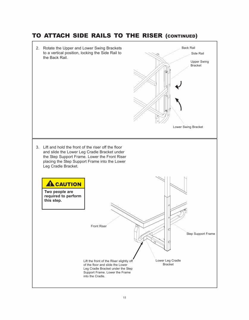
2. Rotate the Upper and Lower Swing Bracketsto a vertical position, locking the Side Rail tothe Back Rail.
Back Rail
Side Rail
Lower Swing Bracket
Upper SwingBracket
3. Lift and hold the front of the riser off the floorand slide the Lower Leg Cradle Bracket underthe Step Support Frame. Lower the Front Riserplacing the Step Support Frame into the LowerLeg Cradle Bracket.
Front Riser
Lower Leg CradleBracket
Step Support Frame
! CAUTIONTwo people arerequired to performthis step.
Lift the front of the Riser slightly offof the floor and slide the LowerLeg Cradle Bracket under the StepSupport Frame. Lower the Frameinto the Cradle.
12
TO ATTACH SIDE RAILS TO THE RISER (CONTINUED)
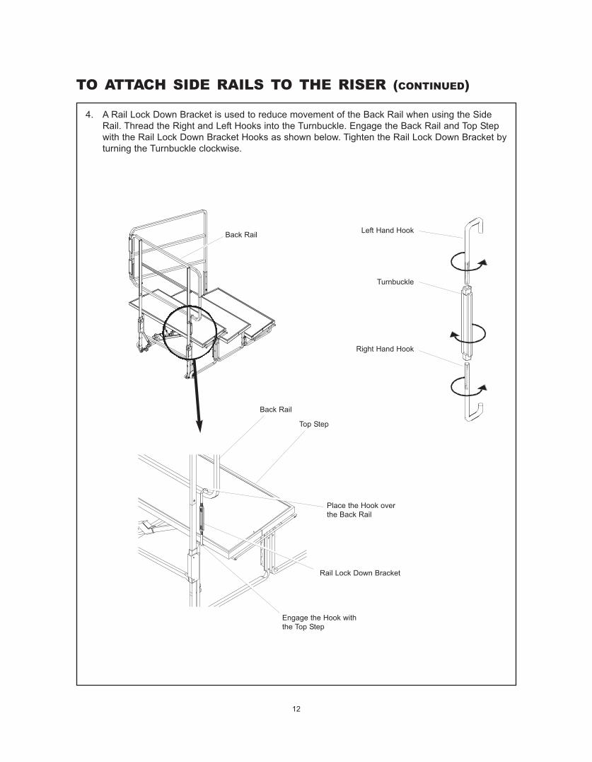
4. A Rail Lock Down Bracket is used to reduce movement of the Back Rail when using the SideRail. Thread the Right and Left Hooks into the Turnbuckle. Engage the Back Rail and Top Stepwith the Rail Lock Down Bracket Hooks as shown below. Tighten the Rail Lock Down Bracket byturning the Turnbuckle clockwise.
Back Rail
Top Step
Rail Lock Down Bracket
Turnbuckle
Left Hand Hook
Right Hand Hook
Back Rail
Engage the Hook withthe Top Step
Place the Hook overthe Back Rail