assembly instructions affordable wheelchair lift …...assembly instructions affordable wheelchair...
TRANSCRIPT
Assembly Instructions Affordable Wheelchair Lift
Model KCSPM3648 (757) 524-3420
Version 3.0.0
1. Introduction Congratulations on your purchase of a new wheelchair lift! We sincerely hope that
this lift will help you accomplish the things that are important to you and those you love.
Note: If you are like me, then you hate reading instructions almost as much as you
hate having to doing things over because you did it wrong. Unfortunately, this product can be assembled backwards, and doing so cannot be remedied without taking it all apart and starting over. These instructions are specifically written to prevent those mistakes. So, please refer to these instructions with each step, and have a pleasant assembly.
Note: The photos in this guide display lifts in various stages of installation. It is
often the case that some recommended safety feature is not yet in place in a specific photo. In particular, the Toe Shear Guard and a basic stair handrail are missing in some of the scenarios we photographed.
Note: There are some minor design changes between different lifts pictured here.
These photos might not exactly match your particular lift. Note: Even if your lift was shipped disassembled, some portions of it may have
been pre assembled for you. Note: If your lift was shipped with some bolts and fasteners already in place and
you find it necessary to temporarily remove them, they must be removed and then re-inserted in the same direction. Inserting the bolt the opposite direction may cause problems.
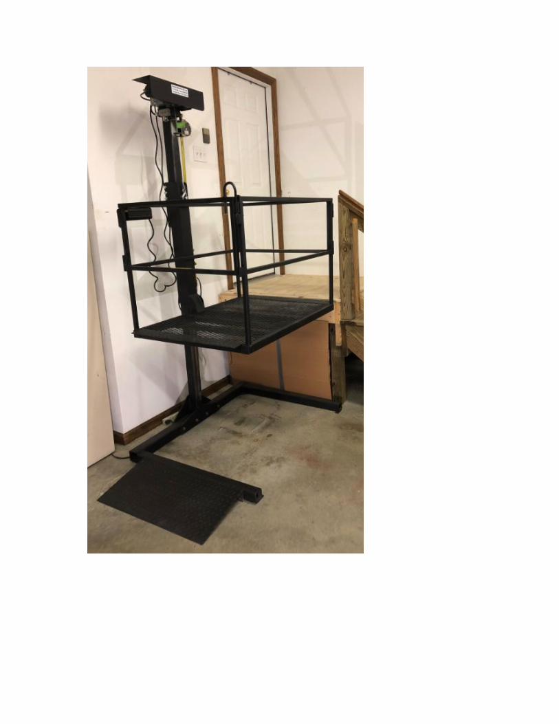
Note: Throughout this document this is used as a caution symbol: Photos of a typical indoor and a typical outdoor installation:

Here is a video of a wheelchair lift in operation:
https://www.youtube.com/watch?v=z47PNqNFF_I
2. Safety Safety is paramount! If you have a question or concern about safe installation or operation please give Affordable Wheelchair Lifts a call. Use common sense when installing or operating this equipment. The installer and operator are responsible for the safe operation of this equipment. It is your responsibility to ensure and verify that this equipment is safely installed. It is your responsibility to know and comply with all applicable legal codes and regulations regarding your wheelchair lift.
Misuse of this equipment can cause serious injury or even death.
3. Assistance If damage has occurred during shipping immediately document it with photographs and notify Affordable Wheelchair Lifts. If you have questions or problems during assembly please give Affordable Wheelchair Lifts a call. We are here to help.
4. A Note On Gates Gates are shipped already assembled and attached to the Platform. You can easily switch the hinging configuration on the gates from left to right. Instructions are below.
5. Assembly Expertise And Physical Ability Requirements
To assemble this equipment you should be familiar with and able to use wrenches, ratchets and sockets, mallets, screwdrivers and a pry-bar. You must be able to turn a wrench to 80 ft/lbs of torque.
6. Required Or Recommended Tools
6.1. Required Tools 6.1.1. ½” wrench (2) 6.1.2. 9/16” wrench (2) 6.1.3. ⅝” wrench (2) 6.1.4. 3/4" wrench (2) 6.1.5. Hammer 6.1.6. Wire cutter 6.1.7. Regular screwdriver 6.1.8. Torque Wrench capable of 80 ft/lbs 6.1.9. Prybar
6.1.10. Vaseline (petroleum jelly) - used to make slip pads stick to metal holder 6.1.11. Temporary support (block, jackstand, or saw horse) 6.2. Recommended Tools
6.2.1. Dolly for moving the Platform 6.2.2. Level 6.2.3. Tapered ½” Drift Pin for aligning bolt holes 6.2.4. Voltmeter (or some other way of establishing that the unit has power) 6.2.5. An additional prybar 6.2.6. Measuring tape 6.2.7. Drop cloth or newspaper to protect floors and walls from paint spray 6.2.8. Stud finder (if attaching bracing to a sheetrock wall) 6.2.9. Short ladder

7. Terminology 7.1. Front, Back, Right and Left - The Column is located on the back side of the
lift. The side of the lift opposite the back side is the front side. Right and left are determined when you face the lift from the front.
7.2. Armless Base - If you lift is wall mounted you may have a lift base with no arms. It would look like this.
7.3. Back Slip Pad Block - This holds the upper back slip pad in place.
7.4. Base With Arms - Free standing lifts must have a base with arms. The Base supports the entire unit. It should be level and can be anchored down. It is shown below without the ramp in place.

7.5. Bracket Cap - Taller lifts require firm bracing at the top of the Column. This is done by attaching beams to a Bracket Cap. This is what a Bracket Cap looks like:
7.6. Brace Kit - Bracing steadies the Column and eliminates any Platform“bounce”. This feature is optional on lifts of 4’ station height or less and is required on medium height lifts between 4’ and 6’. Above 6’ a Bracket Cap approach is required. Below is a photo of our Brace Kit that connects the top of the Column to a nearby wall.

7.7. Bridge(s) - A bridge is the flat diamond plate metal surface attached to each end of the Platform.
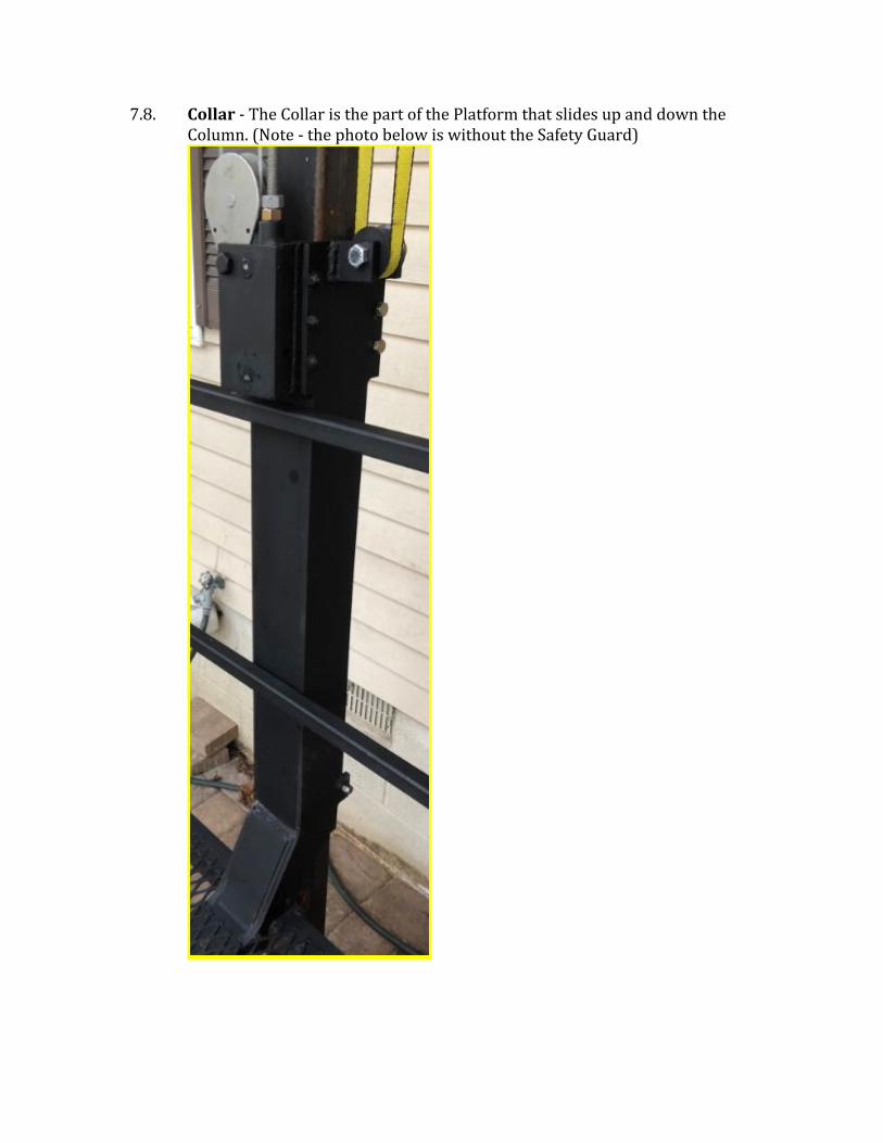
7.8. Collar - The Collar is the part of the Platform that slides up and down the Column. (Note - the photo below is without the Safety Guard)

7.9. Column - Supports the Hoist and the Safety Retractable Lanyard (SRL). (Note - the photo below is without the Safety Guard and also shows an obsolete Hoist Cover)

7.10. Controller - Contains up and down switches. Your model’s Controller may
look different than the ones below. Some controllers have a big red emergency stop button. If the red Emergency Stop button gets pushed it must be manually un-pushed by twisting it.
7.11. Gate(s) - A detachable and reversible Gate is on each end of the Platform. Each Gate has a latch. Your latch may look different than the one in the photo below, as an older style latch is shown.
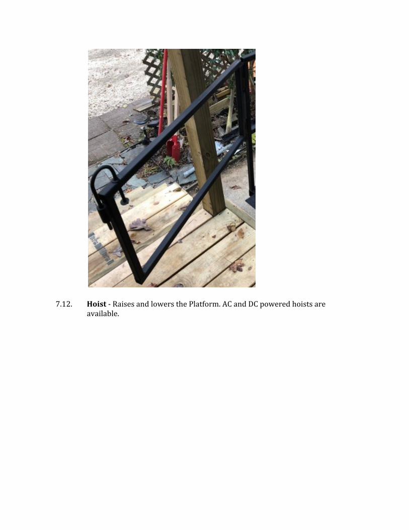
7.12. Hoist - Raises and lowers the Platform. AC and DC powered hoists are available.
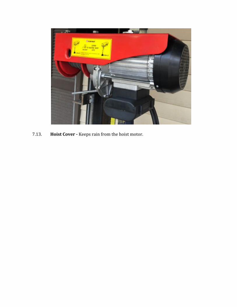
7.13. Hoist Cover - Keeps rain from the hoist motor.

7.14. Hoist Head - The Hoist attaches to the Hoist Head. The Hoist Head mounts on top of the Column. In the photo below the Hoist Head is the black metal part.

7.15. Landing - The upper location where the rider gets on or off the Platform.
7.16. Limit Switch - This switch on the hoist stops the Platform when it reaches a height you preset.

7.17. Limit Switch Actuator - This customer adjustable assembly triggers the Limit Switch to stop the Platform at the Landing height. The photo below shows the various parts of this assembly - the adjustable metal rod, the black EMT/PVC pipe with the trigger, and the grommet (with slot) that protects the cable from wear.
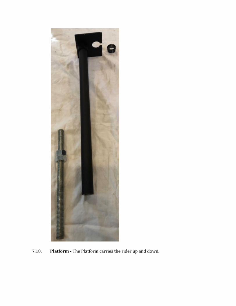
7.18. Platform - The Platform carries the rider up and down.
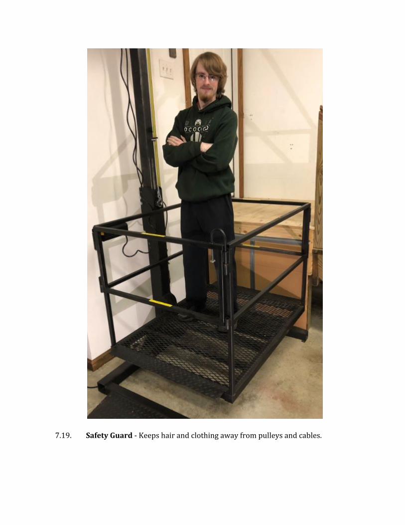
7.19. Safety Guard - Keeps hair and clothing away from pulleys and cables.
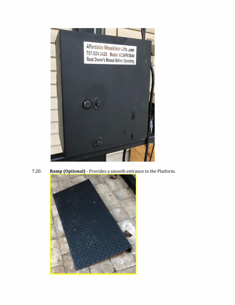
7.20. Ramp (Optional) - Provides a smooth entrance to the Platform.

7.21. SRL (Self Retracting Lifeline) - Serves as a safety backup in case the lifting
mechanism fails. Your model may look different.
7.22. Tether - Connects the controller to the hoist.
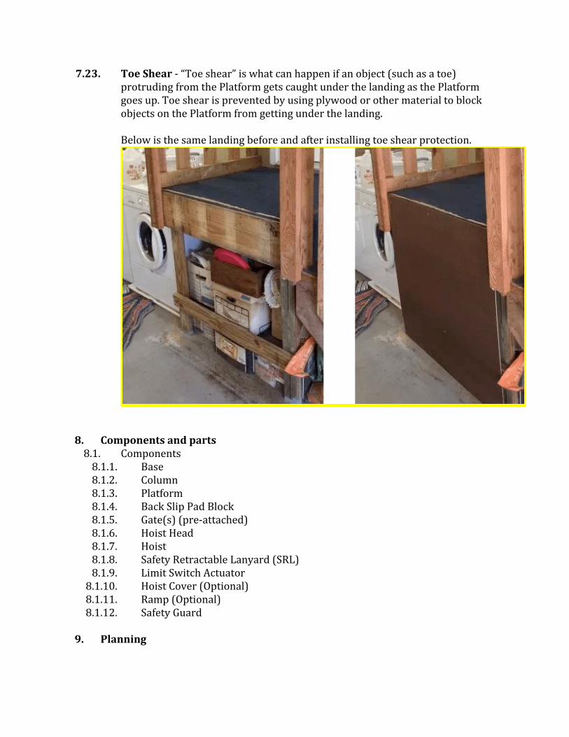
7.23. Toe Shear - “Toe shear” is what can happen if an object (such as a toe) protruding from the Platform gets caught under the landing as the Platform goes up. Toe shear is prevented by using plywood or other material to block objects on the Platform from getting under the landing. Below is the same landing before and after installing toe shear protection.
8. Components and parts
8.1. Components 8.1.1. Base 8.1.2. Column 8.1.3. Platform 8.1.4. Back Slip Pad Block 8.1.5. Gate(s) (pre-attached) 8.1.6. Hoist Head 8.1.7. Hoist 8.1.8. Safety Retractable Lanyard (SRL) 8.1.9. Limit Switch Actuator
8.1.10. Hoist Cover (Optional) 8.1.11. Ramp (Optional) 8.1.12. Safety Guard
9. Planning

Most customers prefer the lift be oriented for straight-through travel from the ramp to the Platform to the landing to inside the home. Sometimes this is not practical. We recommend that if possible, the Column side of the lift be placed closest to a nearby wall. If bracing is desired, then this positioning will make bracing easier.
10. What Should Have When We Are Done
10.1. When going on a journey it helps to know your destination. Below are photos of important sections of the fully assembled lift, with the Hoist Cover and Safety Shields removed.
10.2. Note: The red ring on the end of the hoist cable is probably absent in your model. Please ignore it in the photos.
10.3. Note: The photos in this section are more up to date than the photos in the other sections.
10.4. Here is the Hoist, Hoist Head, SRL and hoist pulley mounted on top of the Column, looking from the platform side.

10.5. Here is the Hoist, Hoist Head, SRL and pulleys mounted on top of the Column, looking from the back side.

10.6. Here is the Hoist, Hoist Head, SRL and pulleys mounted on top of the Column, looking from the left side.

10.7. Here is the Hoist Hook, Pulley Block, Threaded Rod (with nuts) and stop rod. looking from the left/front side.

10.8. Here is how the hoist cables and pulleys should be configured, from the left/front side.


11. Site Preparation Requirements
Before you begin - ● The installation site should be flat and level, clear of debris and as accessible
as possible. ● The lift should sit on a solid surface (concrete, asphalt, etc) or substantial
pavers. ● The landing area should also be flat and level. Toe shear protection should
already be installed. ● Any needed modifications to landing railings, such as cutting away a railing
section or installing a railing safety gate, should be made prior to or during installation.
● Children and pets should be excluded from the area during assembly. ● The amount of electrical power needed to run the lift depends upon which
hoist motor you have chosen. Most require 15 amps. GFI circuits should be used where appropriate. The site in the photo below is clear of obstacles, but the stair railings and toe shear prevention board have yet to be installed.

12. Remove the wheelchair lift from the pallets
What you need: A wrench or socket. An able-bodied adult or two. Remove the plastic wrapping. Remove all the boxes and components from inside the Platform. Slide the Platform off of the Base and off of the pallet. Unbolt the Base from the pallet. Remove the Base from the pallet and discard the pallet.
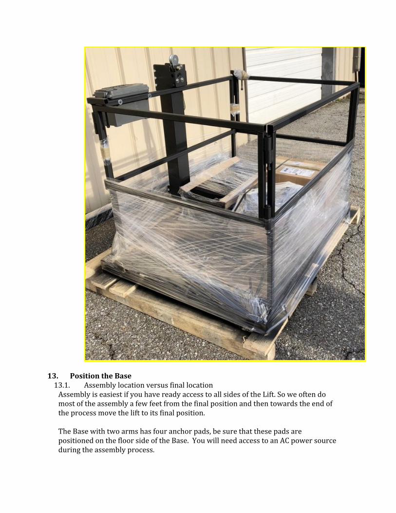
13. Position the Base 13.1. Assembly location versus final location
Assembly is easiest if you have ready access to all sides of the Lift. So we often do most of the assembly a few feet from the final position and then towards the end of the process move the lift to its final position. The Base with two arms has four anchor pads, be sure that these pads are positioned on the floor side of the Base. You will need access to an AC power source during the assembly process.
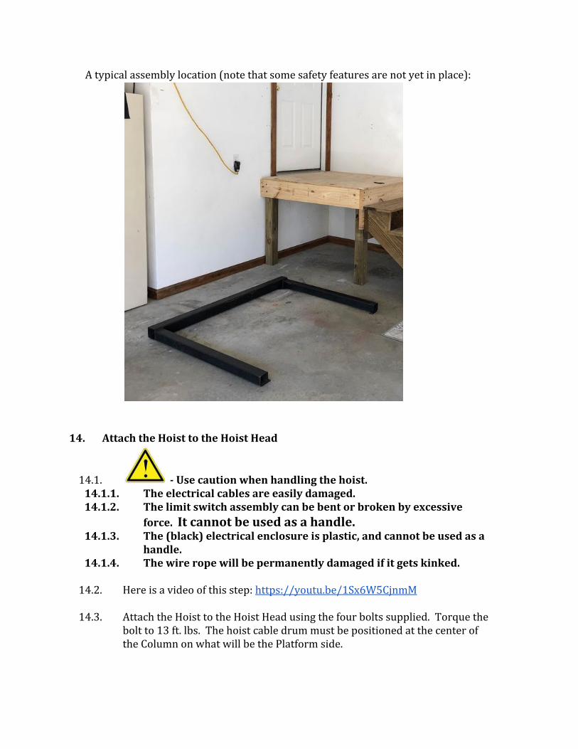
A typical assembly location (note that some safety features are not yet in place):
14. Attach the Hoist to the Hoist Head
14.1. - Use caution when handling the hoist. 14.1.1. The electrical cables are easily damaged. 14.1.2. The limit switch assembly can be bent or broken by excessive
force. It cannot be used as a handle. 14.1.3. The (black) electrical enclosure is plastic, and cannot be used as a
handle. 14.1.4. The wire rope will be permanently damaged if it gets kinked.
14.2. Here is a video of this step: https://youtu.be/1Sx6W5CjnmM
14.3. Attach the Hoist to the Hoist Head using the four bolts supplied. Torque the
bolt to 13 ft. lbs. The hoist cable drum must be positioned at the center of the Column on what will be the Platform side.

14.4. Also attach the cable hook, as shown. Note that the large silver bolts in the upper right of the photo have been replaced on recent units by black set screws.

15. (If you have an Armless Base) Attach the Column to the Base
15.1. Wall mounted lifts can have a base with no arms. When attached to the
column an Armless Base looks like this:

Front:
15.2. Back:
15.3. Side:

15.4. Here is one installed. Note the wooden block between it and the wall that serves to brace it:
15.5. When attaching a Column to an Armless Base be sure the seam on the Column faces to the right or left, not to the front or back. And the vertical flange must face the wall or support it will be bolted to.
16. (If you have a Base with Arms) Attach the Column to the Base
16.1. A free-standing lift must have a base with arms, even if it has a Brace Kit to steady it.
16.2. Here is a video of this step: https://youtu.be/WdD1nXEfCrk
16.3. What you need: The Base and Column. Two ¾” wrenches and/or sockets and ratchets
16.4. Lower the Column over the Base so that the Column flanges straddle the back beam of the Base. It is IMPORTANT that the shorter Column flange is on the inside of the base (towards the side with the base arms). When looking straight along the Column beam ensure that it is parallel with the back beam of the base. Failure to make the Column parallel with the Base will make bolt hole alignment difficult, and bolt insertion impossible.

16.5. Line up the bottom hole in the flange with the end hole of the four (4) hole pattern in the Base. In the case of the illustration below, the BOTTOM hole of the flange must be aligned with the LEFT most hole in the Base.
16.6. Insert a ½-13 x 4 Hex head bolt through the bottom hole. Insert the bolt from the arm side of the Base. By design, the holes are snug on the bolt. It will probably be necessary to tap the bolt through the beams. Do not beat on the bolt if the holes are not aligned. Doing so will only ruin the bolt.
16.7. Install a nut on the bolt. DO NOT TIGHTEN. Once the Column is attached to the Base by a bolt that bolt will serve as a pivot when you later set the Column upright.
17. Attach the Hoist Head
17.1. Here is a video of this step: https://youtu.be/RHXRPaszpU4
17.2. Raise the end of the Column and rest it on a suitable support. This raises it so that the Hoist Head can be attached.

17.3. Carefully attach the Hoist Head by sliding it on the end of the Column. The flat side of the Hoist Head goes to the back of the Column. The cable needs to run down the Platform side of the Column. Secure the Hoist Head by inserting and tightening the Hoist Head bolts. The bolts need only be snug, not tight. Also attach the Hoist Cover to the top of the Hoist Cap. Note - If you are installing bracing then you may wish to install the brace anchor points at this time as well as they use the same bolts as the Hoist Cover. Hoist Covers differ in design. Line up the holes in the Hoist Cover with the holes in the Hoist Cap and insert and secure the bolts.
18. “Walk” the Column upright
18.1. Here is a video of this step: https://youtu.be/Jes-MTH2ggs
18.2. Note: For tall lifts it may be necessary to put the column upright before
attaching the Hoist.
18.3. Before doing this step you may wish to move the platform onto the end of the base arms to secure the Base, as shown below:
18.4. By lifting the Hoist end of the Column, carefully “walk” the Column to a vertical position. Note that the Hoist Head is heavy. This operation may look easy, but it helps to have two people involved.
18.5. Note that the Hoist Head on the end of the column is not displayed in the diagram below.
18.6. - Be careful around the lift at this point. Without the weight of the Platform, the lift is top heavy and not very stable. Especially if the unit is not on a level surface.
18.7. Insert the remaining 3 bolts holding the Column to the base. Tighten all four bolts to 80 ft/lbs.
18.8. Here is a video of this step: https://youtu.be/rbYgvBYk7U4

18.9. Now your Base and Column by themselves look something like this (though your Hoist Head and Hoist Cover may be a different style):
18.10. Do not yet position the lift close to a wall, as you have more work to do on
the back of the Column.
19. Attach the Platform’s Collar to the Column
19.1. Here is a video of this step: https://youtu.be/1qkTeqRj81M
19.2. What you need:
19.2.1. Two 9/16” wrenches and/or sockets 19.2.2. Grease or petroleum jelly 19.2.3. Regular screwdriver
19.3. Move the Platform onto the end of the Base arms.
19.4. Slide the Collar to about a foot away from the Column.
19.5. NOTE: Your plastic slip pads may be white instead of black.
19.6. Clean all of the plastic slip pads of dirt and debris. Ensure that they remain
clean throughout the assembly process. Find one of the two large slip pads
and put a little grease or petroleum jelly on one side of the pad. Use the grease to stick the pad to the inside of the Collar between the pad retainer rails near the bottom of the Collar.
19.7. Here is a video of this step: https://youtu.be/1qkTeqRj81M


19.8. Slide the Platform back so that the Collar surrounds the Column:
19.9. Ensure that the large slip pad has not fallen out. Insert one of the smaller slip pads into the pockets on each side of the Collar. If they are a bit tight you may need to tap them with a hammer and screwdriver, or jiggle the Platform.


19.10. Both lower collar side slip pads are now in place.
19.11. There is no back slip pad for the lower Collar. 19.12. Loosely secure bolt and lock nut.
19.13. Tighten the lock-nut until it will not come off the bolt and no more. The bolt should be able to be spun freely by hand.
19.14. If you over tighten then the Platform will not descend properly under its own weight.
19.15. There is no front slip pad for the top of the Collar.
19.16. Here is a video of this step: https://youtu.be/sNtEJ5L8nTo
19.17. Insert the remaining two small slip pads along the Column at the top of the Collar.
19.18. Position the remaining large slip pad on its holder:

19.19. If you have trouble pulling the Collar close to the column, you can wedge the front of the Platform upwards as shown below:

19.20. Loosely secure the slip pad holder using bolts and lock nuts. There is no top or bottom end for the slip pad block. Tighten the lock-nuts until the bolt does not slide in the holes. The bolts should be able to be spun freely by hand. If you over tighten then the Platform will not descend properly under its own weight.
20. NOTE: 20.1. It is critical that the four (4) adjustment bolts across the back of the collar
are adjusted properly. 20.2. These bolts have Nylock nuts, and do not need to be tight to prevent their
becoming loose. If these bolts are too tight, the platform may bind and may

not descend as the hoist pays out the wire rope. If this happens, the hoist may produce several inches (or feet) of slack, and the platform may then fall until the slack is used up, or the platform will fall until the anti-fall device locks up and stops the platform. Either condition is undesirable.
20.3. Therefore, adjust the three bolts on the back of the top of the collar so that they (the bolts, and the nuts) may be rotated by with finger pressure.
20.4. Adjust the single bolt on the back, near the bottom of the collar so that side to side wobble is acceptable and the unit descends smoothly with no weight in the carriage. It is better to be too loose than too tight.
21. Attach the Pulley Block
21.1. Here is a video of this step: https://youtu.be/6CR5qXSrt_U
21.2. The Pulley Block is where the Hoist cable’s pulley attaches to the Collar.
21.3. Insert the Pulley Block. Insert the ½” bolt through to secure it. Secure the
bolt.
22. Attach the Cable Pulley
22.1. Here is a video of this step: https://youtu.be/uJLEsuZ9Fwk
22.2. - When the hoist has power, anyone with a controller can cause it to activate. If you have wireless controllers for your hoist, then someone in another room playing with a wireless controller can activate the hoist motor. Make sure no one is playing with a controller while the hoist has power and you are working on it or its cables.
22.3. Note - If your lift has two hoist pulleys instead of one then you should follow this diagram:
22.4. What you need:
22.4.1. Components - Hoist and Collar 22.4.2. Tools - ¾” wrench or socket
22.5. Temporarily plug in the hoist power cord so you can operate the hoist:
22.6. Use the hoist’s controller to carefully release enough cable to reach where the cable pulley will be mounted.
- Use gloves when handling the cable. Do not run you hand along the cable, as a loose cable strand can cause a painful injury. This can be true even if you are wearing gloves. Avoid kinking or sharply bending the cable as this reduces the cable strength.
22.7. Attach the cable pulley.
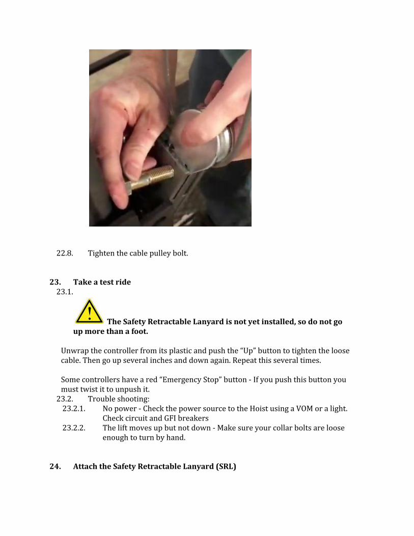
22.8. Tighten the cable pulley bolt.
23. Take a test ride 23.1.
The Safety Retractable Lanyard is not yet installed, so do not go up more than a foot.
Unwrap the controller from its plastic and push the “Up” button to tighten the loose cable. Then go up several inches and down again. Repeat this several times. Some controllers have a red “Emergency Stop” button - If you push this button you must twist it to unpush it.
23.2. Trouble shooting: 23.2.1. No power - Check the power source to the Hoist using a VOM or a light.
Check circuit and GFI breakers 23.2.2. The lift moves up but not down - Make sure your collar bolts are loose
enough to turn by hand.
24. Attach the Safety Retractable Lanyard (SRL)

24.1. Here is a video of this step: https://youtu.be/ZrylaTCa7QU
24.2. What you need: 24.2.1. Components - SRL 24.2.2. Tools 24.2.3. Parts
24.3. Attach the SRL’s cable hook to the inner hole on the Hoist Head.
24.4. Rotate the SRL body so that it will not interfere with the Limit Switch. Make sure the SRL strap is not twisted and then attach the SRL’s carabiner through the outer hole.


24.5. Your SRL model and its cable or strap may be different from what is shown here.
24.6. SRL cable pulley
24.6.1. Do not twist the SRL cable 24.6.2. Attach and secure the SRL cable pulley
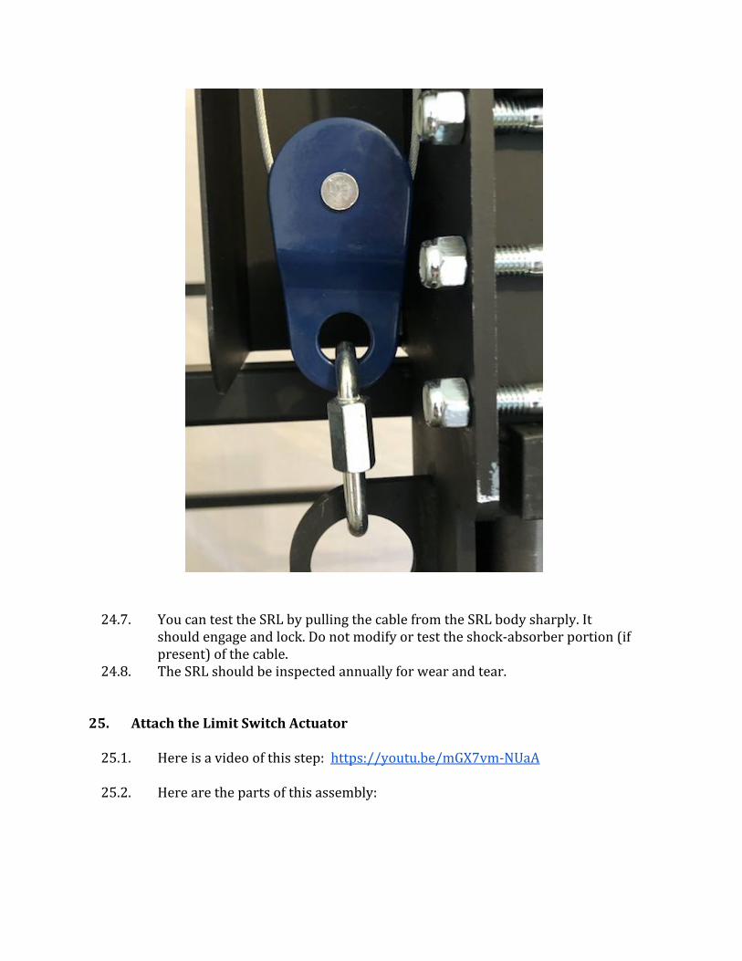
24.7. You can test the SRL by pulling the cable from the SRL body sharply. It
should engage and lock. Do not modify or test the shock-absorber portion (if present) of the cable.
24.8. The SRL should be inspected annually for wear and tear.
25. Attach the Limit Switch Actuator
25.1. Here is a video of this step: https://youtu.be/mGX7vm-NUaA
25.2. Here are the parts of this assembly:
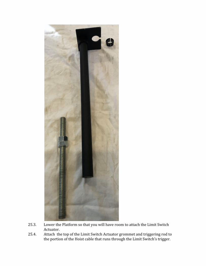
25.3. Lower the Platform so that you will have room to attach the Limit Switch
Actuator. 25.4. Attach the top of the Limit Switch Actuator grommet and triggering rod to
the portion of the Hoist cable that runs through the Limit Switch’s trigger.


25.5. Insert the Limit Switch Actuator metal rod into the Pulley Block. Either end can go in and it will spin freely. Remember that you will use the nuts to adjust the lift stop height.

25.6. Place the top plastic rod over the bottom metal rod.
26. Adjust the Lift’s Maximum Height
26.1. Here is a video of this step: https://youtu.be/7UeOlV95g4g
26.2. Adjust the nut on the Limit Switch Actuator so that the Limit Switch is triggered at the desired Platform height for your Landing. The process for doing this is outlined below.
26.3. Note that you can do the following adjusting process with or without the Safety Guard in place. The metal rod can just slide out once you remove the plastic rod.
26.4. With the plastic rod seated on the metal rod, carefully use the controller to raise the platform until the limit switch stops it. Measure your current Platform height. Then do one of the following steps. (Repeat this process until the Platform stops at the height you desire.)
26.4.1. If the Platform stops at your desired height, then tighten the nuts to each other to prevent them from moving. You have now completed the step of adjusting the lift’s maximum height.
26.4.2. If the Platform stops lower than you want, then shorten the limit switch actuator to allow the Platform to go higher:
26.4.2.1. Determine how many inches higher you want the Platform to actually go.
26.4.2.2. Lower the platform a bit to give you some slack to work with. 26.4.2.3. (You can do the steps below without removing the Safety Guard. The
metal rod can just slide out once you remove the plastic rod.)

26.4.2.4. Shorten the limit switch actuator by the number of needed inches by lowering the nuts on the metal rod.
26.4.2.5. Do not lower the nuts any lower than 2” from the lower end of the metal rod, or the rod will not be stable it its slot.
26.4.2.6. If you cannot lower the nuts enough you can always easily cut the plastic rod with a knife or saw to be slightly shorter. Do not accidentally cut the plastic rod too short or else you will need to either replace the plastic rod or purchase a longer metal rod.
26.4.3. If the Platform stops higher than you want, then lengthen the limit switch actuator to force the Platform to stop lower:
26.4.3.1. Determine how many inches lower you want the Platform to actually go.
26.4.3.2. Lower the platform a bit to give you some slack to work with. 26.4.3.3. (You can do the steps below without removing the Safety Guard. The
metal rod can just slide out once you remove the plastic rod.) 26.4.3.4. Lengthen the limit switch actuator by the number of needed inches
by raising the nuts on the metal rod. 26.4.3.5. Do not raise the nuts any higher than 2” from the upper end of the
metal rod, or the upper rod will not be stable on the lower rod. 26.4.3.6. If you cannot raise the nuts enough you can always replace the
plastic rod with a longer one. The upper rod is simply 1” diameter EMT pipe that can be bought at any hardware store and easily cut to a different length. It is pressure fitted onto the trigger plate, so you can easily attach the trigger mechanism to your new pipe.
27. Attach the Safety Guard
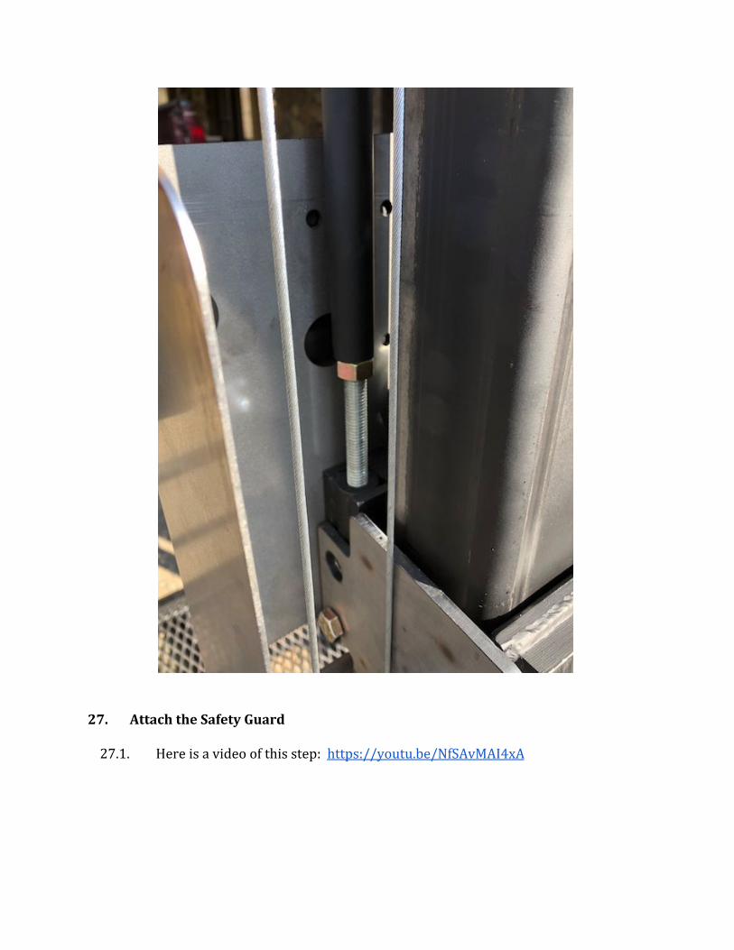
27.1. Here is a video of this step: https://youtu.be/NfSAvMAI4xA
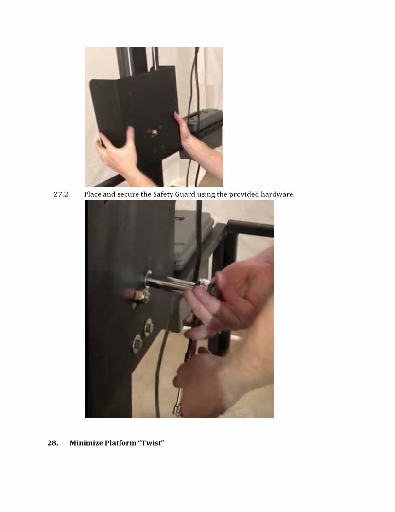
27.2. Place and secure the Safety Guard using the provided hardware.
28. Minimize Platform “Twist”

28.1. Here is a video of this step: https://youtu.be/9kfdEt_R3vg
28.2. Platform “twist” is the side to side movement of the Platform around the Column’s vertical axis. Twist can be minimized by carefully tightening the Collar bolt on the lower Collar.
28.3. If you over tighten the Collar bolts then the platform will not be able to
descend under its own weight. If this happens then loosen the Collar bolts.
29. A Note on the next steps 29.1. Most of the next, final steps interact with each other, and may end up
needing to be repeated as you fine tune your lift. For instance, levelling your lift may require re-adjusting the bracing. If you choose to bolt your lift down, you may need to uninstall and reinstall bracing and shims as a part of that process. Think ahead to minimize rework, but realize that some adjusting and repetition may be needed. Do what is best for your situation.
30. (Optional) Wheels 30.1. This lift can be moved with a dolly or a pry-bar. If you are doing multiple lift
installations or plan to occasionally move your lift you may wish to invest in a set of detachable wheels for moving the lift’s base. Contact Affordable Wheelchair Lifts.
31. Move the lift to its potential final position
31.1. What you need: 31.1.1. Components 31.1.2. Tools 31.1.3. Parts
31.2. Now use a crowbar and some muscle to move the lift into its final position. A dolly might be useful.
31.3. Do not level or shim the lift yet. We will do that later.
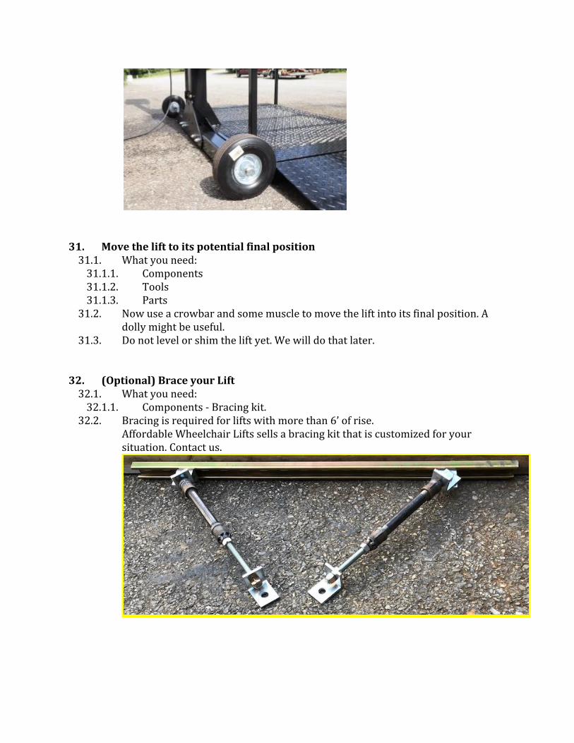
32. (Optional) Brace your Lift
32.1. What you need: 32.1.1. Components - Bracing kit.
32.2. Bracing is required for lifts with more than 6’ of rise. Affordable Wheelchair Lifts sells a bracing kit that is customized for your situation. Contact us.

32.3. See the bracing kit instructions for installation.
33. Position the Entry Ramp 33.1. What you need:
33.1.1. Components - Ramp 33.1.2. Tools 33.1.3. Parts
33.2. The ramp sits on the floor next to one of the base arms. A “U” shaped metal connector can optionally be used to keep the ramp from moving over time. This connector rests on its back with one of its arms on the inside of the base’s arm and the other of its arms on the inside of the ramp’s vertical back.
34. Position and Level your Lift

34.1. What you need: 34.1.1. Components 34.1.2. Tools - Spirit level 34.1.3. Parts
34.2. Use a level and shims to shim the base so that the lift is level. 34.3. You want the edge of the Bridge to be around ¼” from the toe shear board
all along the Platform’s travel, and especially at the top.
35. Wrap Up
35.1. Here is a video of this step: https://youtu.be/uMsfcsGBHOY
36. (Optional) Anchor your lift to the floor 36.1. What you need:
36.1.1. Tools 36.1.2. Parts
36.2. - Do not anchor the lift down until you are sure of the final lift locations. Make sure the gates are properly working and interacting with the landing railings first!
36.3. There are four anchor points built in to the lift base. 36.4. Drilling - If on a concrete pad then drill deep enough so that the anchor can
be hammered down into the floor once the lift is removed. 36.5. Anchoring
37. Gates (re-positioning)
37.1. Here is a video of this step: https://youtu.be/Jze2HWZAxvM

37.2. What you need:
37.2.1. Tools - wrenches and/or sockets 37.2.2. Parts - bolts and lock-nuts
37.3. Each gate comes pre-attached to the Platform. Gate and latch styles may vary. Each gate can hinge on either the right or the left side. The default is to hinge on the left side when entering Platform from either direction.
37.4. This gate is hinged on the left side.
37.5. You can detach easily detach a gate and switch the side it hinges from. 37.6. To change the hinge side for a gate remove the two bolts and lock-nuts to
detach the gate. Position the gate hinges the way you want them, then re-insert and fasten the bolts to re-attach a gate.
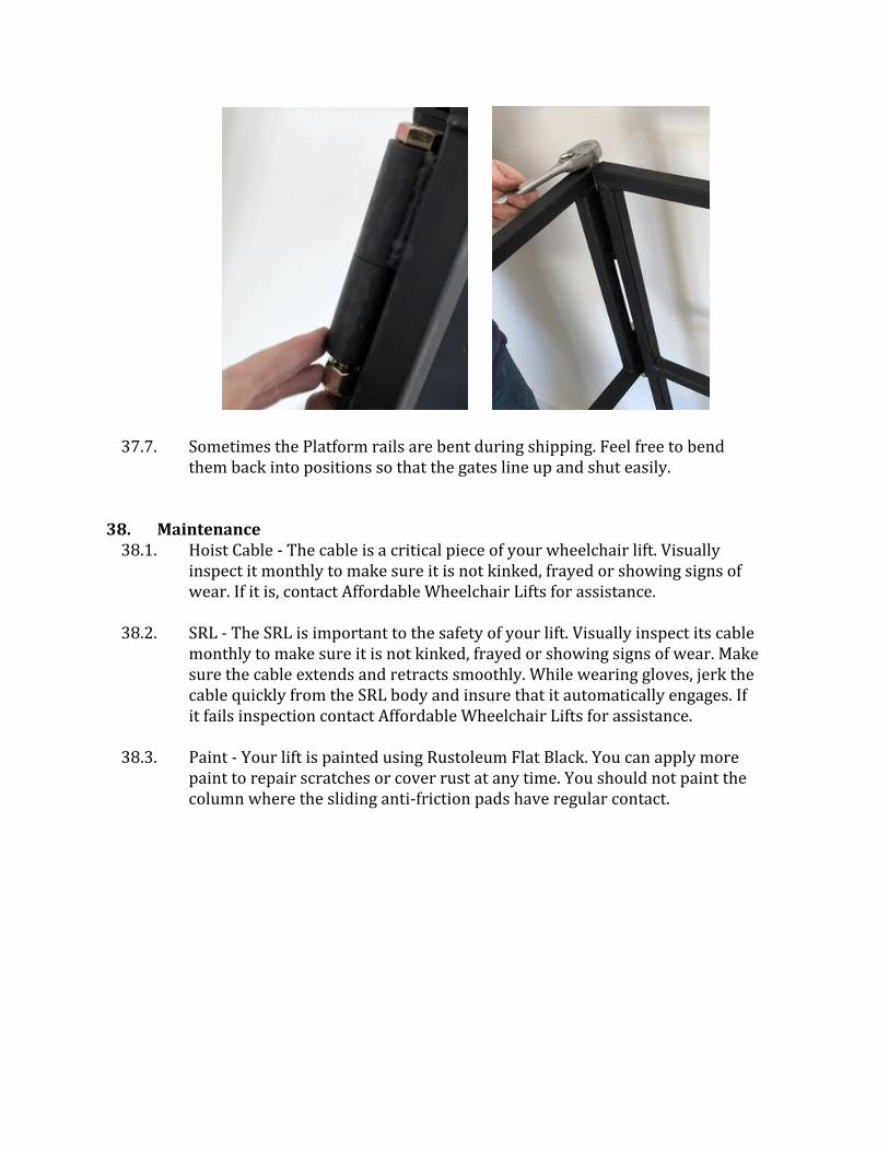
37.7. Sometimes the Platform rails are bent during shipping. Feel free to bend them back into positions so that the gates line up and shut easily.
38. Maintenance
38.1. Hoist Cable - The cable is a critical piece of your wheelchair lift. Visually inspect it monthly to make sure it is not kinked, frayed or showing signs of wear. If it is, contact Affordable Wheelchair Lifts for assistance.
38.2. SRL - The SRL is important to the safety of your lift. Visually inspect its cable
monthly to make sure it is not kinked, frayed or showing signs of wear. Make sure the cable extends and retracts smoothly. While wearing gloves, jerk the cable quickly from the SRL body and insure that it automatically engages. If it fails inspection contact Affordable Wheelchair Lifts for assistance.
38.3. Paint - Your lift is painted using Rustoleum Flat Black. You can apply more
paint to repair scratches or cover rust at any time. You should not paint the column where the sliding anti-friction pads have regular contact.