armstrong fluid technology | ashrae qatar oryx … · achieving ashrae 90.1 and 189.1 with...
TRANSCRIPT
Achieving ASHRAE 90.1 and 189.1 with Armstrong Design Envelope Green Building Solutions - ASHRAE Seminar 2014|May 03, 2014
Armstrong Fluid Technology | ASHRAE QATAR ORYX CHAPTER - Seminar 2014
Achieving ASHRAE 90.1 and 189.1 with Armstrong Design Envelope Green Building Solutions
Achieving ASHRAE 90.1 and 189.1 with Armstrong Design Envelope Green Building Solutions - ASHRAE Seminar 2014|May 03, 2014
Achieving ASHRAE 90.1 and 189.1 with Armstrong Design Envelope Green Building Solutions - ASHRAE Seminar 2014|May 03, 2014
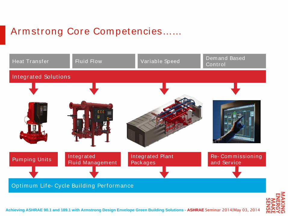
Heat Transfer Fluid Flow Variable Speed Demand Based Control
Integrated Solutions
Pumping Units Integrated Fluid Management
Re-Commissioning and Service
Integrated Plant Packages
Optimum Life-Cycle Building Performance
Armstrong Core Competencies……
Achieving ASHRAE 90.1 and 189.1 with Armstrong Design Envelope Green Building Solutions - ASHRAE Seminar 2014|May 03, 2014
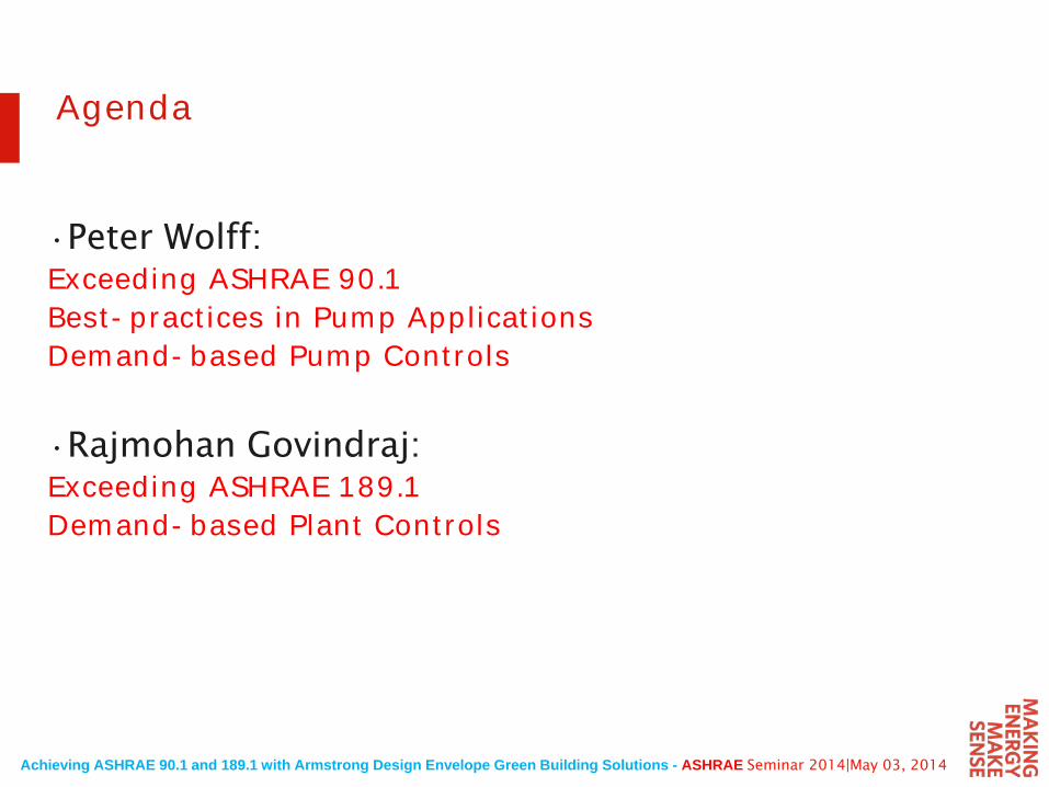
Agenda
•Peter Wolff: Exceeding ASHRAE 90.1 Best-practices in Pump ApplicationsDemand-based Pump Controls
•Rajmohan Govindraj:Exceeding ASHRAE 189.1 Demand-based Plant Controls
Achieving ASHRAE 90.1 and 189.1 with Armstrong Design Envelope Green Building Solutions - ASHRAE Seminar 2014|May 03, 2014
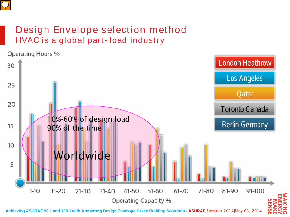
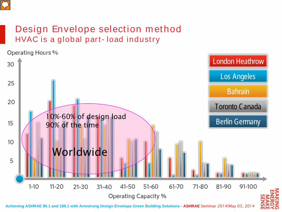
London Heathrow
Los Angeles
Qatar
Toronto Canada
Berlin Germany10%-60% of design load 90% of the time
Worldwide
Design Envelope selection methodHVAC is a global part-load industry
Achieving ASHRAE 90.1 and 189.1 with Armstrong Design Envelope Green Building Solutions - ASHRAE Seminar 2014|May 03, 2014
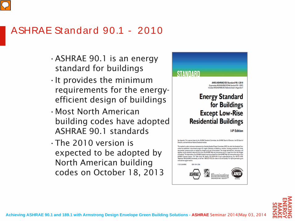
ASHRAE Standard 90.1 - 2010
•ASHRAE 90.1 is an energy standard for buildings
•It provides the minimum requirements for the energy-efficient design of buildings
•Most North American building codes have adopted ASHRAE 90.1 standards
•The 2010 version is expected to be adopted by North American building codes on October 18, 2013
Achieving ASHRAE 90.1 and 189.1 with Armstrong Design Envelope Green Building Solutions - ASHRAE Seminar 2014|May 03, 2014
ASHRAE 90.1- 20106.5.4 Hydronic system design and control
• “6.5.4.1 Hydronic variable flow systems• Individual chilled water pumps serving variable
flow systems having motors exceeding 5hp(3.7kW) shall have controls and / or devices(Such as variable speed control) that will result inpump motor demand of no more than 30% ofdesign wattage at 50% of design water flow”
• Note that the ASHRAE 90.1-2010 requirement starts at 5hp (3.7kW) motors.
• Compare this to the 2007 version which started at 50hp (37kW)
• Progress to all pumps 1hp (0.75kW) and over having integrated controls
Achieving ASHRAE 90.1 and 189.1 with Armstrong Design Envelope Green Building Solutions - ASHRAE Seminar 2014|May 03, 2014
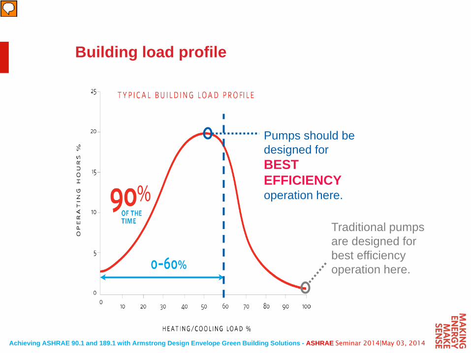
Building load profile
Traditional pumpsare designed for best efficiencyoperation here.
Pumps should bedesigned forBESTEFFICIENCYoperation here.
Achieving ASHRAE 90.1 and 189.1 with Armstrong Design Envelope Green Building Solutions - ASHRAE Seminar 2014|May 03, 2014
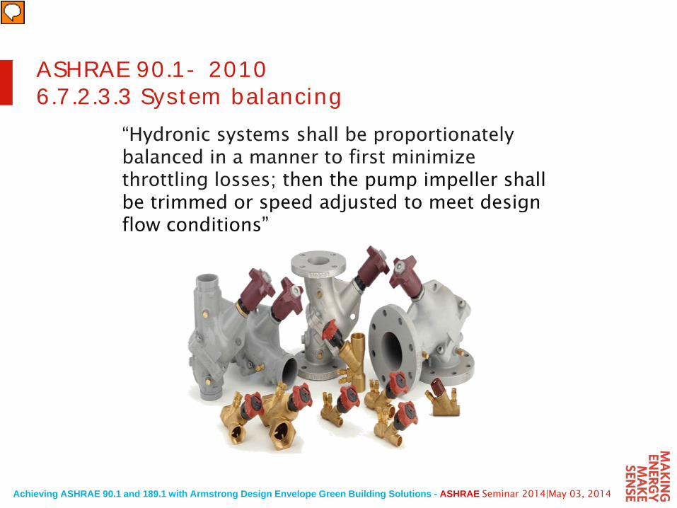
“Hydronic systems shall be proportionately balanced in a manner to first minimize throttling losses; then the pump impeller shall be trimmed or speed adjusted to meet design flow conditions”
ASHRAE 90.1- 20106.7.2.3.3 System balancing
Achieving ASHRAE 90.1 and 189.1 with Armstrong Design Envelope Green Building Solutions - ASHRAE Seminar 2014|May 03, 2014
Flow
Hea
d/P
ress
ure
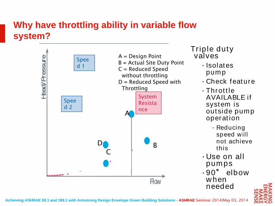
Why have throttling ability in variable flow system?
Triple duty valves• Isolates
pump•Check feature•Throttle
AVAILABLE if system is outside pump operation• Reducing
speed will not achieve this
•Use on all pumps
•90° elbow when needed
System Resistance
Speed 1
Speed 2
A
D
A = Design PointB = Actual Site Duty Point C = Reduced Speed
without throttlingD = Reduced Speed with
Throttling
BC
Achieving ASHRAE 90.1 and 189.1 with Armstrong Design Envelope Green Building Solutions - ASHRAE Seminar 2014|May 03, 2014
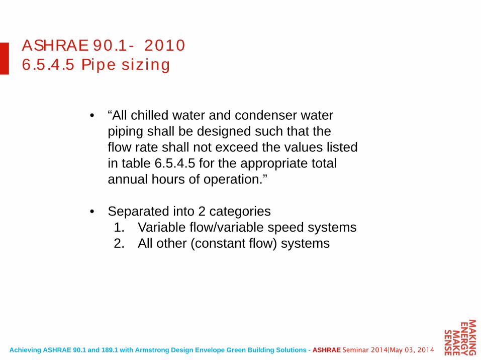
ASHRAE 90.1- 20106.5.4.5 Pipe sizing
• “All chilled water and condenser water piping shall be designed such that the flow rate shall not exceed the values listed in table 6.5.4.5 for the appropriate total annual hours of operation.”
• Separated into 2 categories1. Variable flow/variable speed systems2. All other (constant flow) systems
Achieving ASHRAE 90.1 and 189.1 with Armstrong Design Envelope Green Building Solutions - ASHRAE Seminar 2014|May 03, 2014
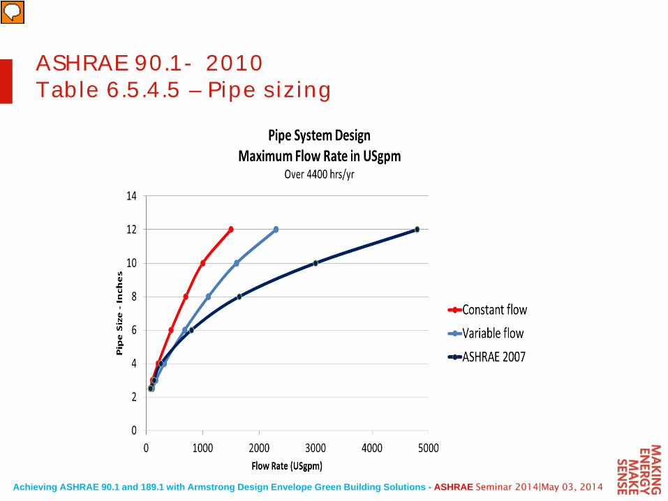
ASHRAE 90.1- 2010Table 6.5.4.5 – Pipe sizing
Achieving ASHRAE 90.1 and 189.1 with Armstrong Design Envelope Green Building Solutions - ASHRAE Seminar 2014|May 03, 2014
ASHRAE 90.1- 20106.5.4.5 Pipe sizing
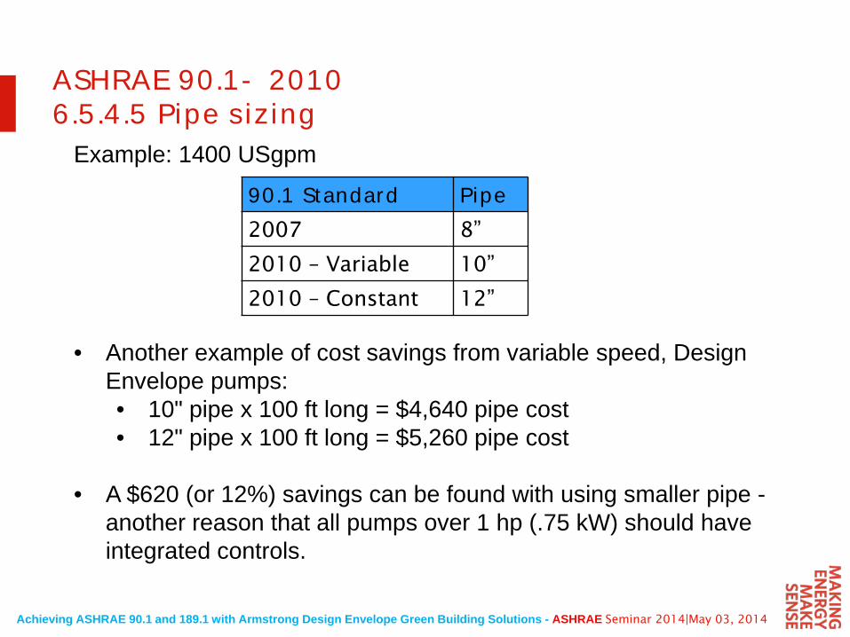
Example: 1400 USgpm
• Another example of cost savings from variable speed, Design Envelope pumps:• 10" pipe x 100 ft long = $4,640 pipe cost• 12" pipe x 100 ft long = $5,260 pipe cost
• A $620 (or 12%) savings can be found with using smaller pipe -another reason that all pumps over 1 hp (.75 kW) should have integrated controls.
90.1 Standard Pipe2007 8”
2010 – Variable 10”
2010 – Constant 12”
Achieving ASHRAE 90.1 and 189.1 with Armstrong Design Envelope Green Building Solutions - ASHRAE Seminar 2014|May 03, 2014
HVAC pump requirements in ASHRAE 90.1
Energy savings through:
• Flow control• Balancing• Pipe sizing
Achieving ASHRAE 90.1 and 189.1 with Armstrong Design Envelope Green Building Solutions - ASHRAE Seminar 2014|May 03, 2014
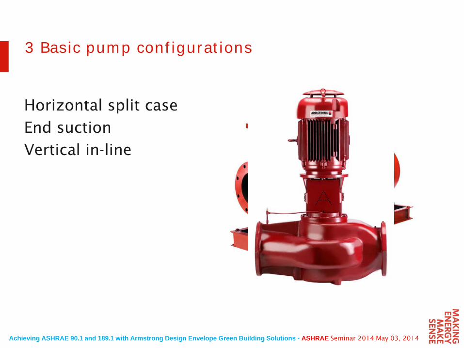
3 Basic pump configurations
Horizontal split case
End suction
Vertical in-line
Achieving ASHRAE 90.1 and 189.1 with Armstrong Design Envelope Green Building Solutions - ASHRAE Seminar 2014|May 03, 2014
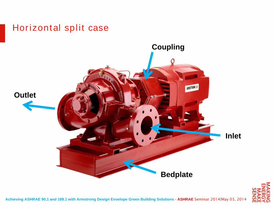
Horizontal split case
Inlet
Outlet
Coupling
Bedplate
Achieving ASHRAE 90.1 and 189.1 with Armstrong Design Envelope Green Building Solutions - ASHRAE Seminar 2014|May 03, 2014
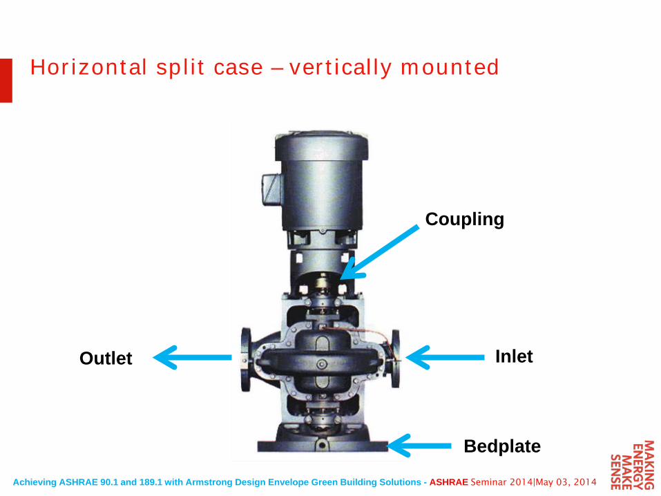
Horizontal split case – vertically mounted
InletOutlet
Coupling
Bedplate
Achieving ASHRAE 90.1 and 189.1 with Armstrong Design Envelope Green Building Solutions - ASHRAE Seminar 2014|May 03, 2014
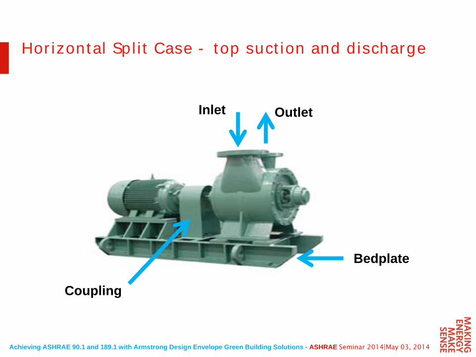
Horizontal Split Case - top suction and discharge
Inlet Outlet
Coupling
Bedplate
Achieving ASHRAE 90.1 and 189.1 with Armstrong Design Envelope Green Building Solutions - ASHRAE Seminar 2014|May 03, 2014
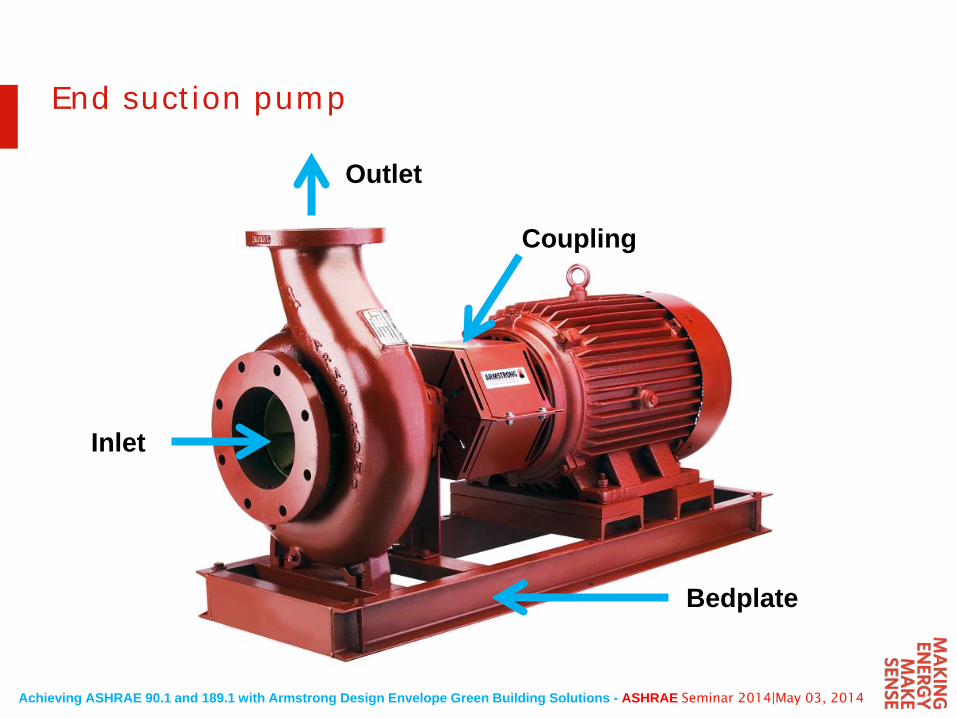
End suction pump
Inlet
Outlet
Coupling
Bedplate
Achieving ASHRAE 90.1 and 189.1 with Armstrong Design Envelope Green Building Solutions - ASHRAE Seminar 2014|May 03, 2014
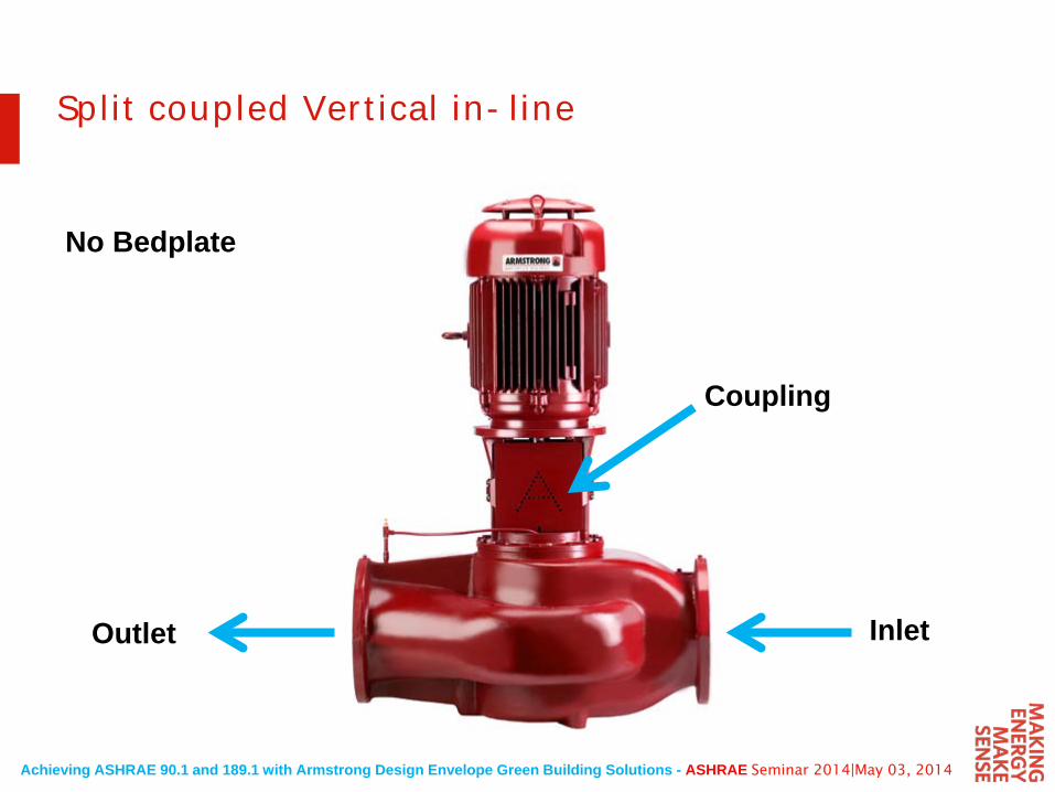
Split coupled Vertical in-line
InletOutlet
Coupling
No Bedplate
Achieving ASHRAE 90.1 and 189.1 with Armstrong Design Envelope Green Building Solutions - ASHRAE Seminar 2014|May 03, 2014
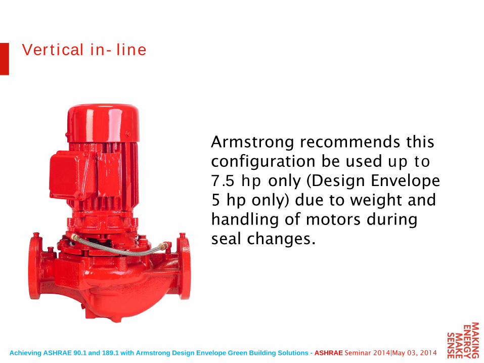
Armstrong recommends this configuration be used up to 7.5 hp only (Design Envelope 5 hp only) due to weight and handling of motors during seal changes.
Vertical in-line
Achieving ASHRAE 90.1 and 189.1 with Armstrong Design Envelope Green Building Solutions - ASHRAE Seminar 2014|May 03, 2014
Which is the bestconfigurationfor the application?
Achieving ASHRAE 90.1 and 189.1 with Armstrong Design Envelope Green Building Solutions - ASHRAE Seminar 2014|May 03, 2014
A. Floor space
B. Ease of installation
C. Maintainability
D. Reliability
E. Energy costs
F. Sustainability – Product Life Cycle
Consider six major criteria
Achieving ASHRAE 90.1 and 189.1 with Armstrong Design Envelope Green Building Solutions - ASHRAE Seminar 2014|May 03, 2014
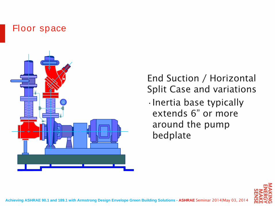
End Suction / Horizontal Split Case and variations
•Inertia base typically extends 6” or more around the pump bedplate
Floor space
Achieving ASHRAE 90.1 and 189.1 with Armstrong Design Envelope Green Building Solutions - ASHRAE Seminar 2014|May 03, 2014
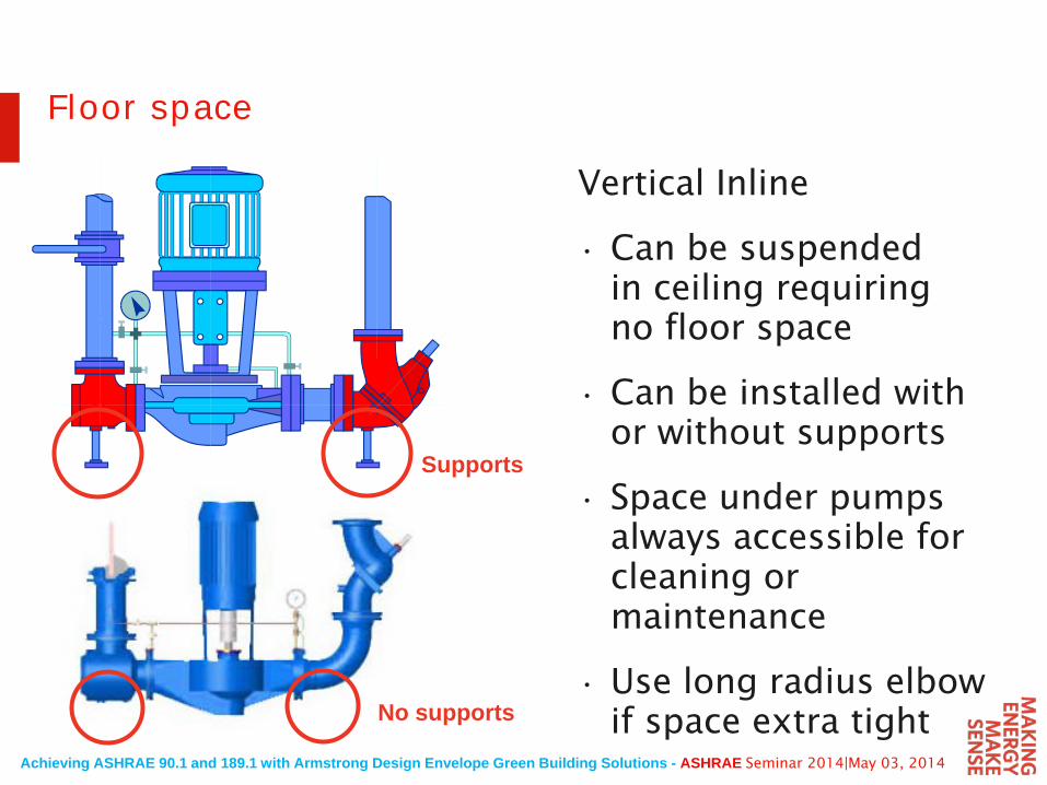
Vertical Inline
• Can be suspended in ceiling requiring no floor space
• Can be installed with or without supports
• Space under pumps always accessible for cleaning or maintenance
• Use long radius elbow if space extra tight
Floor space
Supports
No supports
Achieving ASHRAE 90.1 and 189.1 with Armstrong Design Envelope Green Building Solutions - ASHRAE Seminar 2014|May 03, 2014
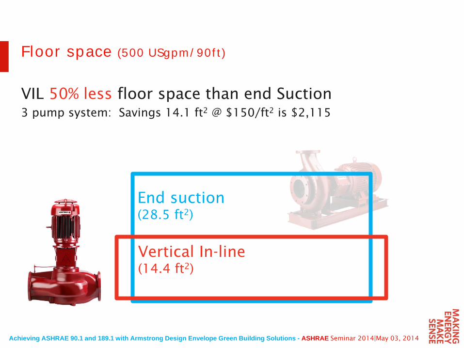
Floor space (500 USgpm/90ft)
End suction (28.5 ft2)
VIL 50% less floor space than end Suction3 pump system: Savings 14.1 ft2 @ $150/ft2 is $2,115
Vertical In-line (14.4 ft2)
Achieving ASHRAE 90.1 and 189.1 with Armstrong Design Envelope Green Building Solutions - ASHRAE Seminar 2014|May 03, 2014
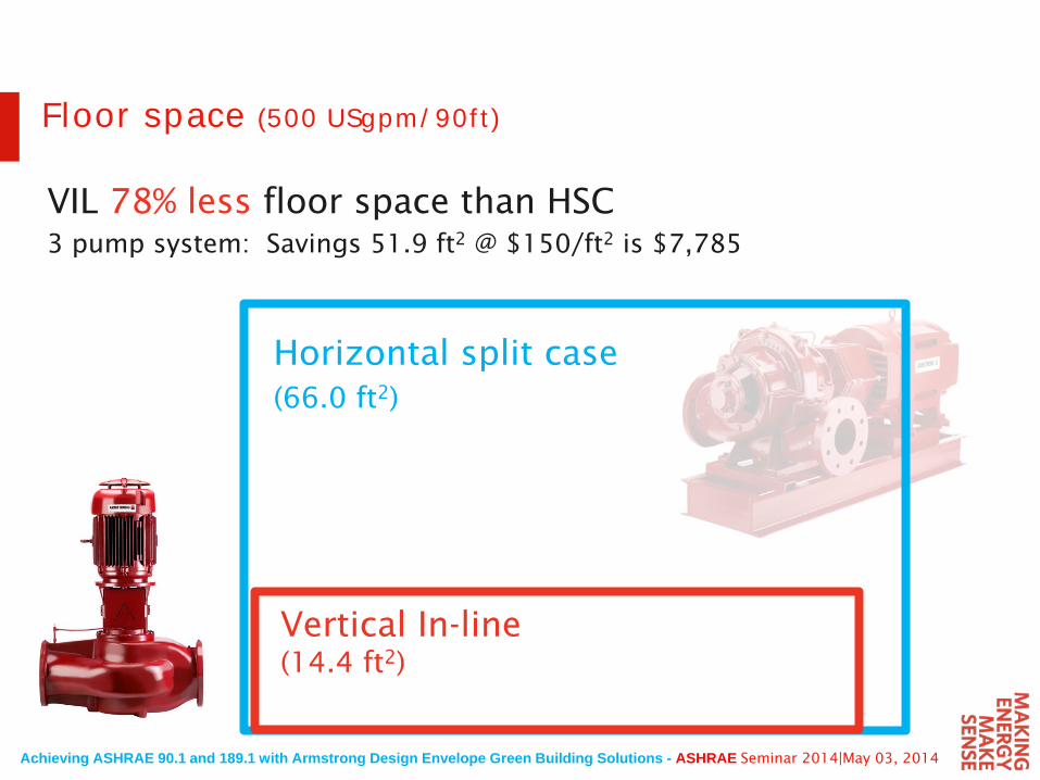
Floor space (500 USgpm/90ft)
VIL 78% less floor space than HSC3 pump system: Savings 51.9 ft2 @ $150/ft2 is $7,785
Horizontal split case(66.0 ft2)
Vertical In-line (14.4 ft2)
Achieving ASHRAE 90.1 and 189.1 with Armstrong Design Envelope Green Building Solutions - ASHRAE Seminar 2014|May 03, 2014
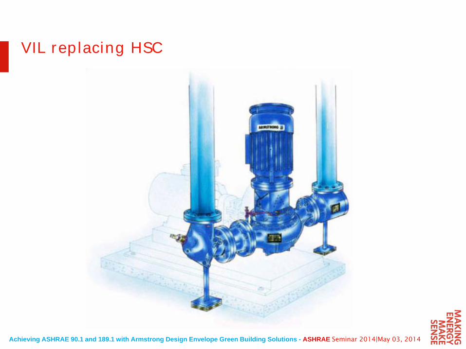
VIL replacing HSC
Achieving ASHRAE 90.1 and 189.1 with Armstrong Design Envelope Green Building Solutions - ASHRAE Seminar 2014|May 03, 2014
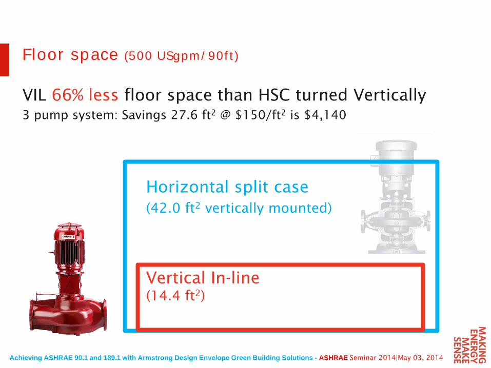
Floor space (500 USgpm/90ft)
VIL 66% less floor space than HSC turned Vertically3 pump system: Savings 27.6 ft2 @ $150/ft2 is $4,140
Vertical In-line (14.4 ft2)
Horizontal split case(42.0 ft2 vertically mounted)
Achieving ASHRAE 90.1 and 189.1 with Armstrong Design Envelope Green Building Solutions - ASHRAE Seminar 2014|May 03, 2014
VerticalIn- Line
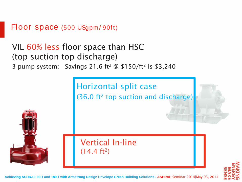
Floor space (500 USgpm/90ft)
VIL 60% less floor space than HSC (top suction top discharge)3 pump system: Savings 21.6 ft2 @ $150/ft2 is $3,240
Horizontal split case(36.0 ft2 top suction and discharge)
Vertical In-line (14.4 ft2)
Achieving ASHRAE 90.1 and 189.1 with Armstrong Design Envelope Green Building Solutions - ASHRAE Seminar 2014|May 03, 2014
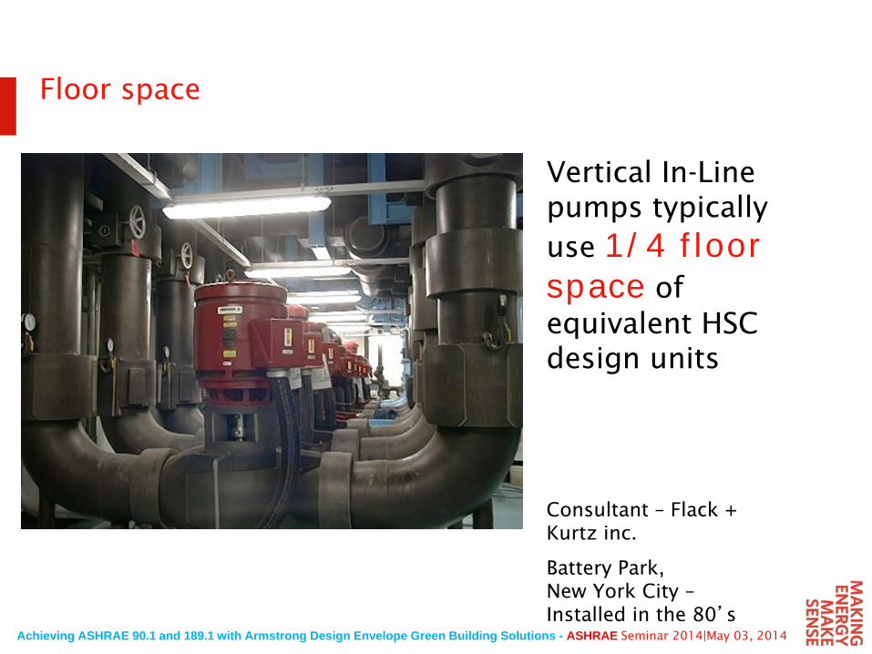
Vertical In-Line pumps typically use 1/4 floor space of equivalent HSC design units
Floor space
Consultant – Flack + Kurtz inc.
Battery Park, New York City –Installed in the 80’s
Achieving ASHRAE 90.1 and 189.1 with Armstrong Design Envelope Green Building Solutions - ASHRAE Seminar 2014|May 03, 2014
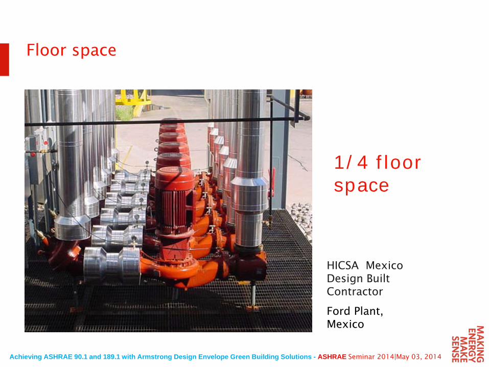
Floor space
1/4 floor space
HICSA MexicoDesign Built Contractor
Ford Plant, Mexico
Achieving ASHRAE 90.1 and 189.1 with Armstrong Design Envelope Green Building Solutions - ASHRAE Seminar 2014|May 03, 2014
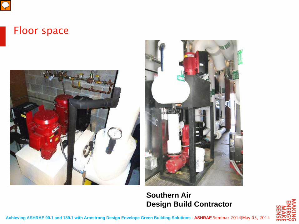
Floor space
Southern AirDesign Build Contractor
Achieving ASHRAE 90.1 and 189.1 with Armstrong Design Envelope Green Building Solutions - ASHRAE Seminar 2014|May 03, 2014
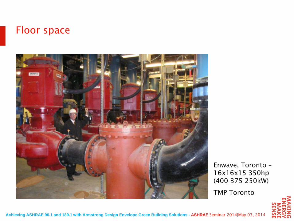
Floor space
Enwave, Toronto –16x16x15 350hp(400-375 250kW)
TMP Toronto
Achieving ASHRAE 90.1 and 189.1 with Armstrong Design Envelope Green Building Solutions - ASHRAE Seminar 2014|May 03, 2014
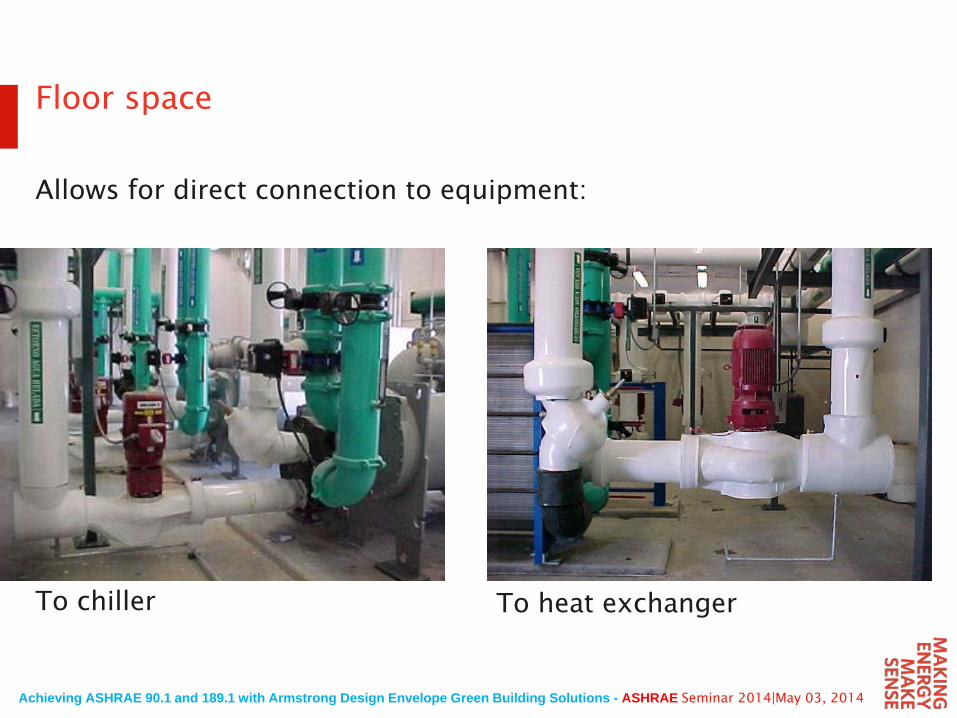
Floor space
Allows for direct connection to equipment:
To chiller To heat exchanger
Achieving ASHRAE 90.1 and 189.1 with Armstrong Design Envelope Green Building Solutions - ASHRAE Seminar 2014|May 03, 2014
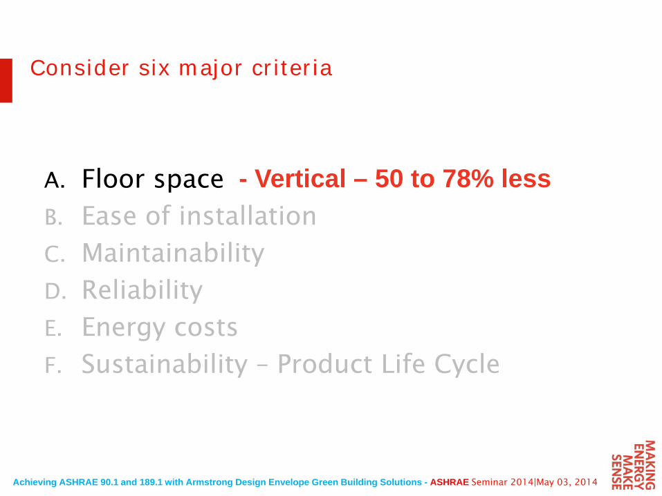
A. Floor space
B. Ease of installation
C. Maintainability
D. Reliability
E. Energy costs
F. Sustainability – Product Life Cycle
Consider six major criteria
- Vertical – 50 to 78% less
Achieving ASHRAE 90.1 and 189.1 with Armstrong Design Envelope Green Building Solutions - ASHRAE Seminar 2014|May 03, 2014
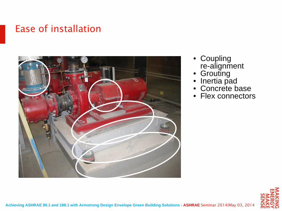
• Coupling re-alignment
• Grouting• Inertia pad• Concrete base• Flex connectors
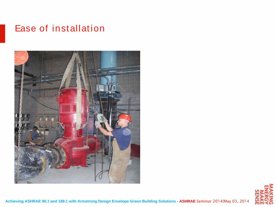
Ease of installation
Achieving ASHRAE 90.1 and 189.1 with Armstrong Design Envelope Green Building Solutions - ASHRAE Seminar 2014|May 03, 2014
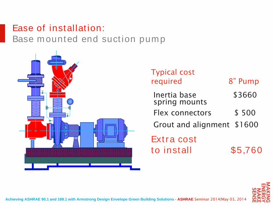
Typical costrequired 8” Pump
Inertia base $3660spring mounts
Flex connectors $ 500
Grout and alignment $1600
Extra cost to install $5,760
Ease of installation:Base mounted end suction pump
Achieving ASHRAE 90.1 and 189.1 with Armstrong Design Envelope Green Building Solutions - ASHRAE Seminar 2014|May 03, 2014
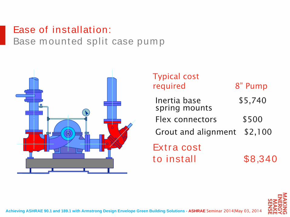
Ease of installation:Base mounted split case pump
Typical costrequired 8” Pump
Inertia base $5,740spring mounts
Flex connectors $500
Grout and alignment $2,100
Extra cost to install $8,340
Achieving ASHRAE 90.1 and 189.1 with Armstrong Design Envelope Green Building Solutions - ASHRAE Seminar 2014|May 03, 2014
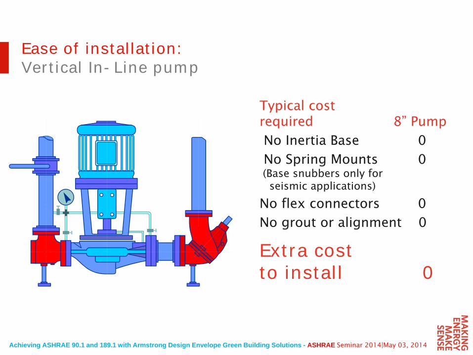
Typical cost required 8” Pump
No Inertia Base 0
No Spring Mounts 0 (Base snubbers only forseismic applications)
No flex connectors 0
No grout or alignment 0
Extra cost to install 0
Ease of installation:Vertical In-Line pump
Achieving ASHRAE 90.1 and 189.1 with Armstrong Design Envelope Green Building Solutions - ASHRAE Seminar 2014|May 03, 2014
Ease of installation
Achieving ASHRAE 90.1 and 189.1 with Armstrong Design Envelope Green Building Solutions - ASHRAE Seminar 2014|May 03, 2014
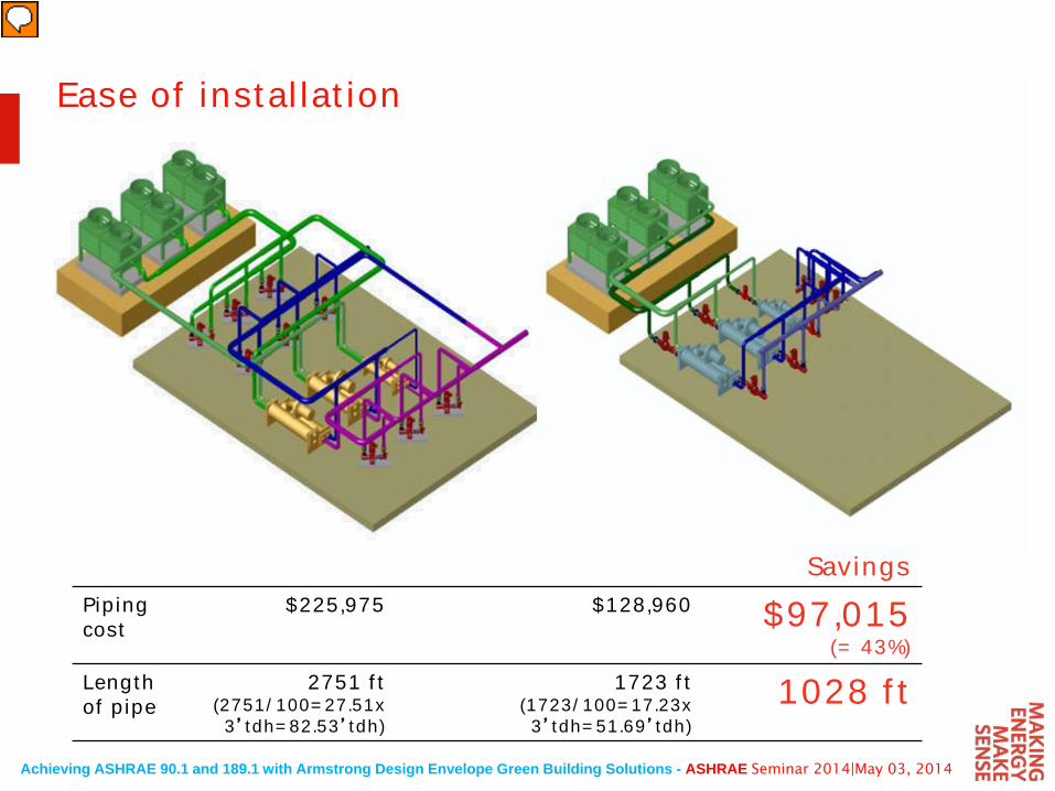
SavingsPiping cost
$225,975 $128,960 $97,015(= 43%)
Length of pipe
2751 ft(2751/100=27.51x3’tdh=82.53’tdh)
1723 ft(1723/100=17.23x3’tdh=51.69’tdh)
1028 ft
Ease of installation
Achieving ASHRAE 90.1 and 189.1 with Armstrong Design Envelope Green Building Solutions - ASHRAE Seminar 2014|May 03, 2014
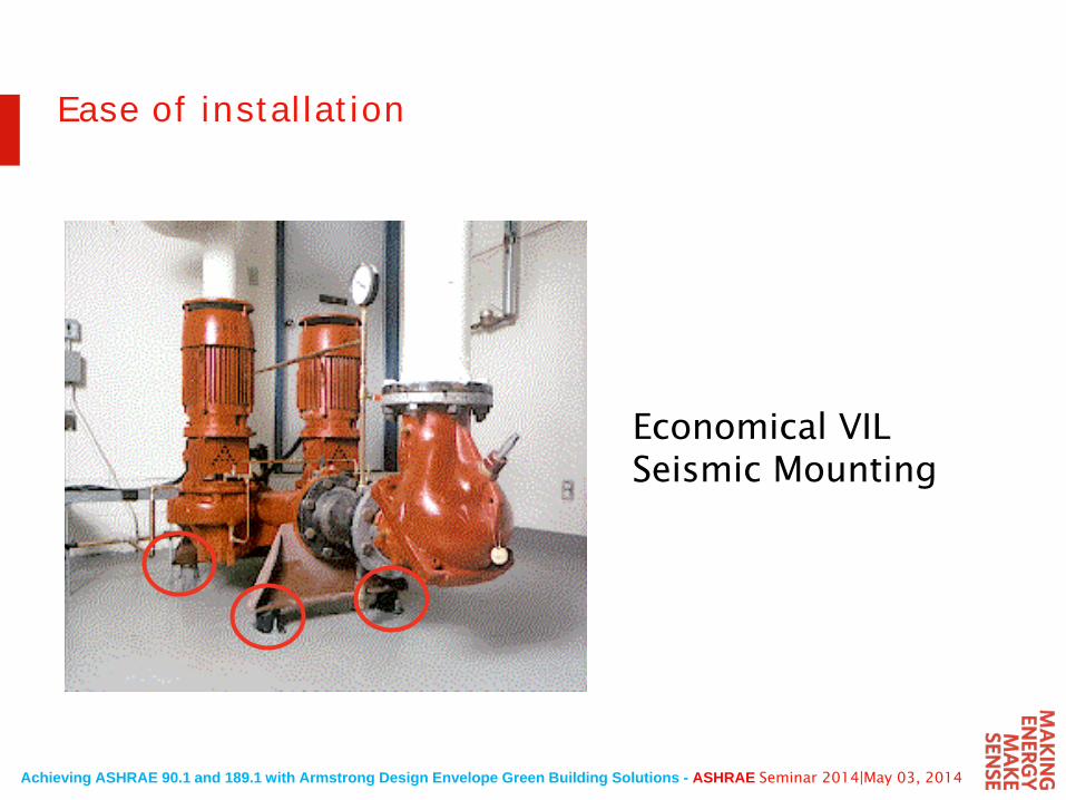
Economical VIL Seismic Mounting
Ease of installation
Achieving ASHRAE 90.1 and 189.1 with Armstrong Design Envelope Green Building Solutions - ASHRAE Seminar 2014|May 03, 2014
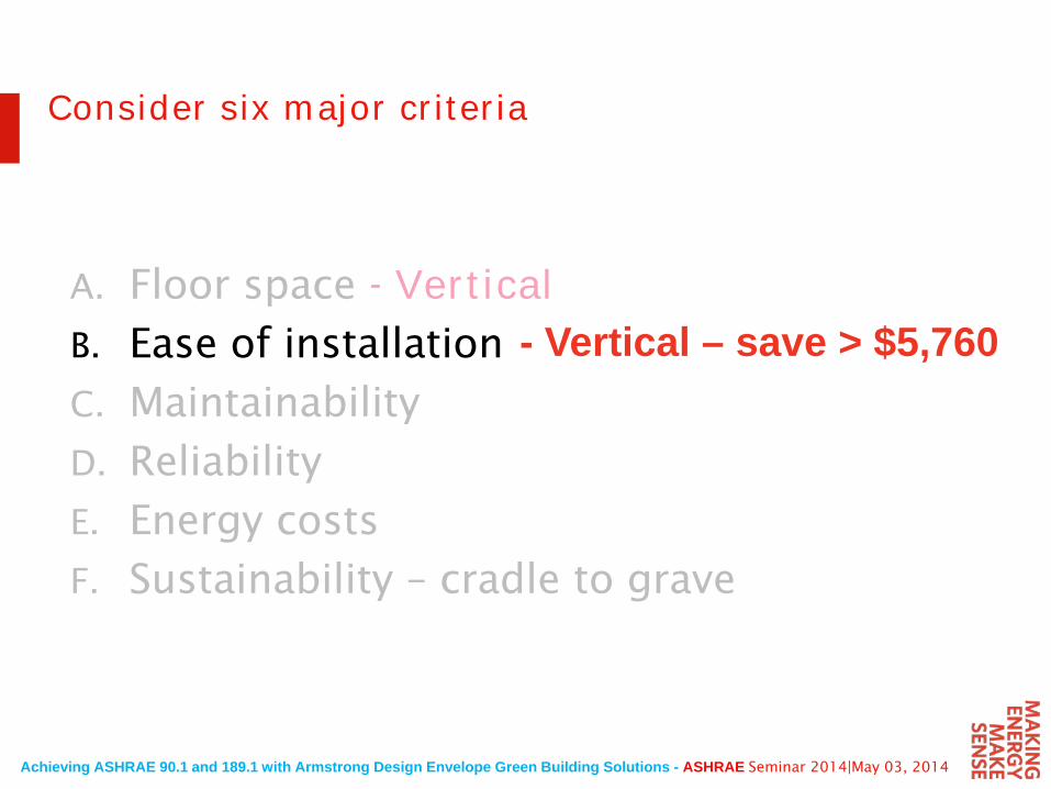
A. Floor space - VerticalB. Ease of installation
C. Maintainability
D. Reliability
E. Energy costs
F. Sustainability – cradle to grave
Consider six major criteria
- Vertical – save > $5,760
Achieving ASHRAE 90.1 and 189.1 with Armstrong Design Envelope Green Building Solutions - ASHRAE Seminar 2014|May 03, 2014
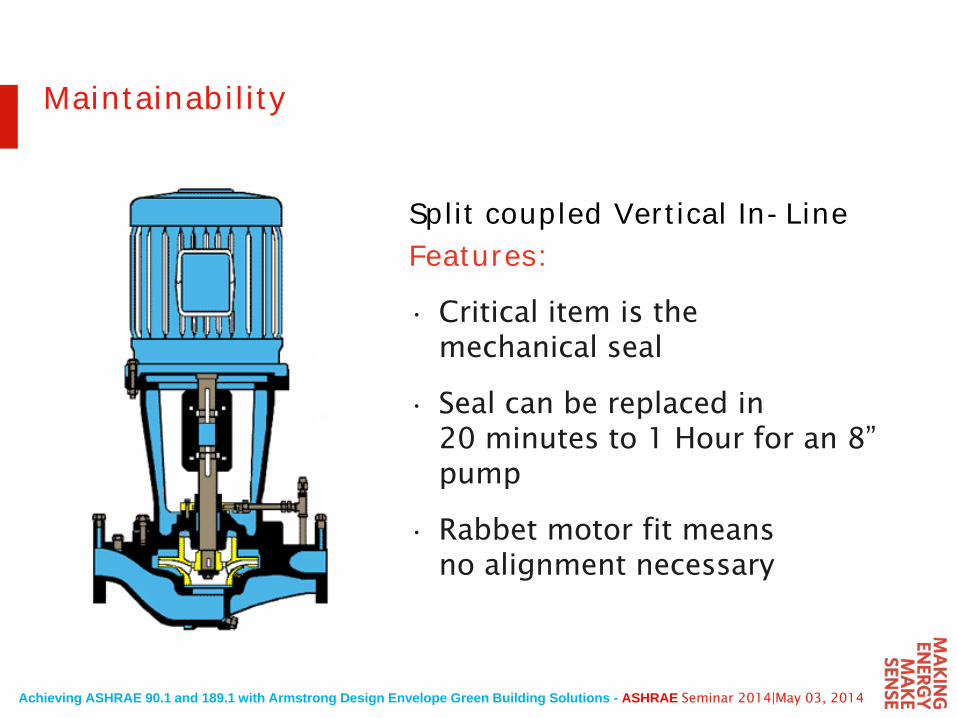
Split coupled Vertical In-LineFeatures:
• Critical item is the mechanical seal
• Seal can be replaced in 20 minutes to 1 Hour for an 8” pump
• Rabbet motor fit means no alignment necessary
Maintainability
Achieving ASHRAE 90.1 and 189.1 with Armstrong Design Envelope Green Building Solutions - ASHRAE Seminar 2014|May 03, 2014
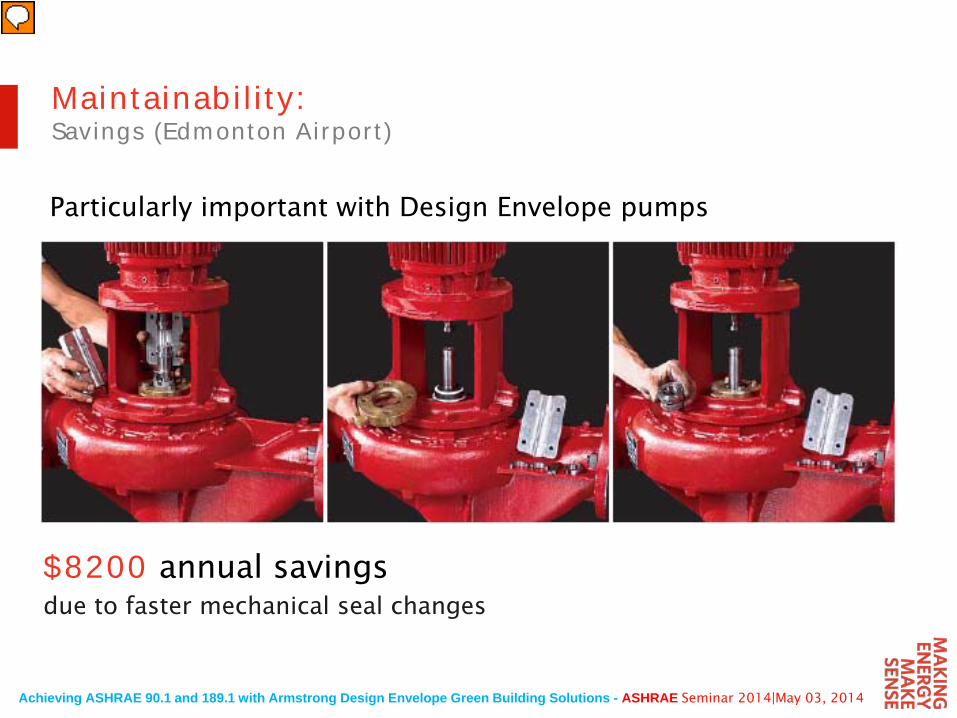
$8200 annual savingsdue to faster mechanical seal changes
Maintainability:Savings (Edmonton Airport)
Particularly important with Design Envelope pumps
Achieving ASHRAE 90.1 and 189.1 with Armstrong Design Envelope Green Building Solutions - ASHRAE Seminar 2014|May 03, 2014
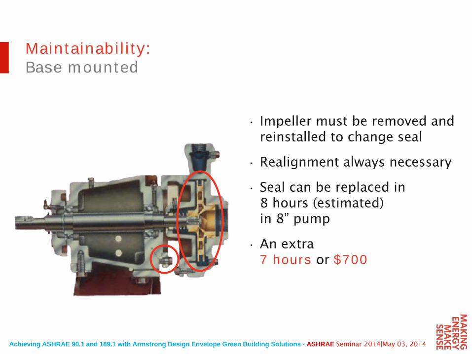
• Impeller must be removed and reinstalled to change seal
• Realignment always necessary
• Seal can be replaced in 8 hours (estimated) in 8” pump
• An extra 7 hours or $700
Maintainability:Base mounted
Achieving ASHRAE 90.1 and 189.1 with Armstrong Design Envelope Green Building Solutions - ASHRAE Seminar 2014|May 03, 2014
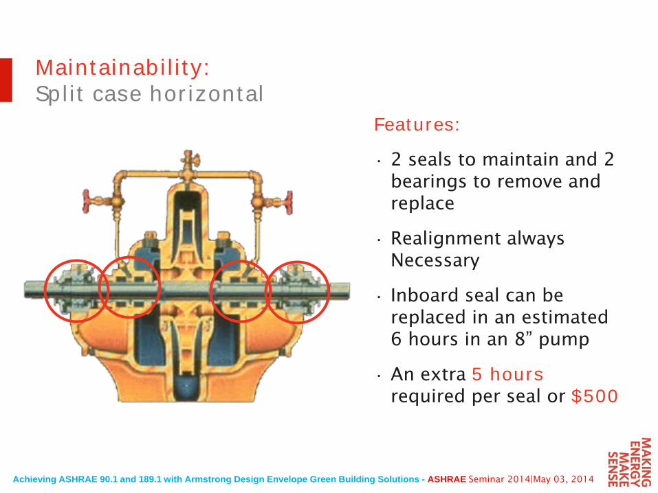
Features:
• 2 seals to maintain and 2 bearings to remove and replace
• Realignment always Necessary
• Inboard seal can be replaced in an estimated 6 hours in an 8” pump
• An extra 5 hours required per seal or $500
Maintainability:Split case horizontal
Achieving ASHRAE 90.1 and 189.1 with Armstrong Design Envelope Green Building Solutions - ASHRAE Seminar 2014|May 03, 2014
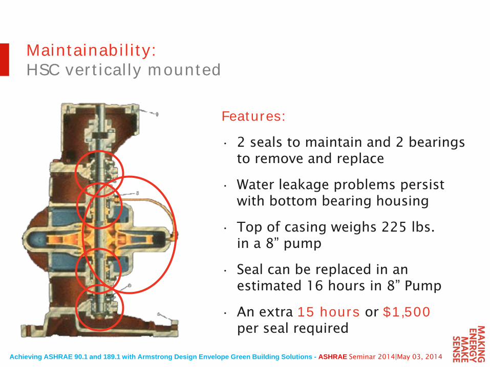
Features:
• 2 seals to maintain and 2 bearings to remove and replace
• Water leakage problems persist with bottom bearing housing
• Top of casing weighs 225 lbs.in a 8” pump
• Seal can be replaced in an estimated 16 hours in 8” Pump
• An extra 15 hours or $1,500 per seal required
Maintainability:HSC vertically mounted
Achieving ASHRAE 90.1 and 189.1 with Armstrong Design Envelope Green Building Solutions - ASHRAE Seminar 2014|May 03, 2014
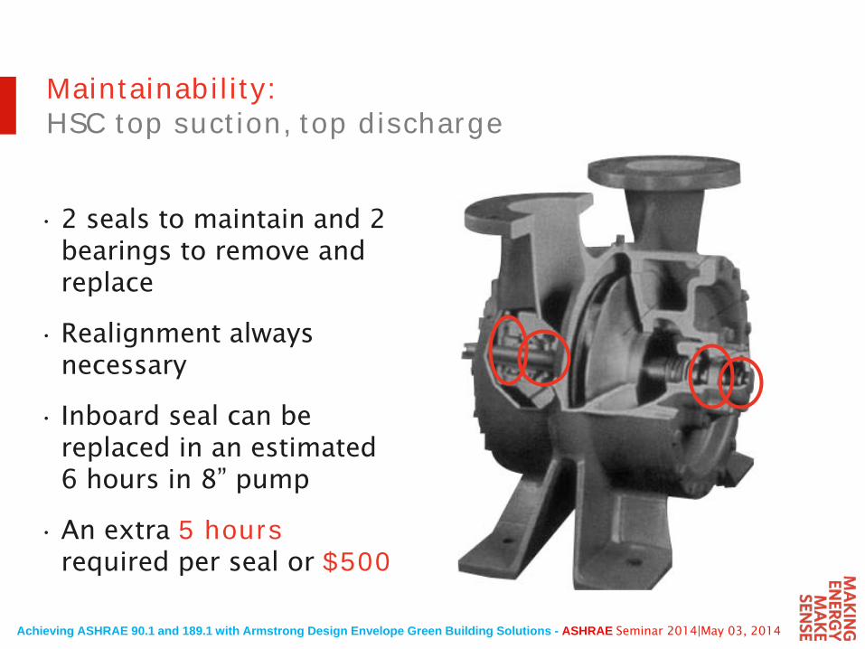
• 2 seals to maintain and 2 bearings to remove and replace
• Realignment always necessary
• Inboard seal can be replaced in an estimated 6 hours in 8” pump
• An extra 5 hours required per seal or $500
Maintainability:HSC top suction, top discharge
Achieving ASHRAE 90.1 and 189.1 with Armstrong Design Envelope Green Building Solutions - ASHRAE Seminar 2014|May 03, 2014
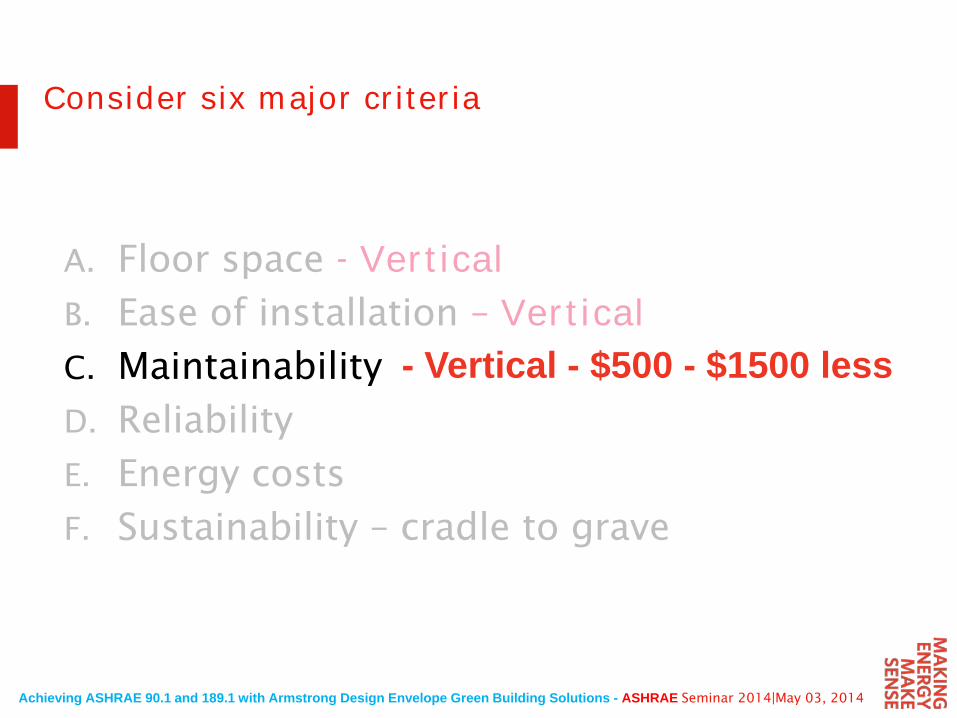
A. Floor space - VerticalB. Ease of installation – VerticalC. Maintainability
D. Reliability
E. Energy costs
F. Sustainability – cradle to grave
Consider six major criteria
- Vertical - $500 - $1500 less
Achieving ASHRAE 90.1 and 189.1 with Armstrong Design Envelope Green Building Solutions - ASHRAE Seminar 2014|May 03, 2014
The vertical configuration has been proven in thousands of installations for over 50 years
Horsepower is available up to 1250 hp and discharge sizes available larger than 20”
Reliability
Achieving ASHRAE 90.1 and 189.1 with Armstrong Design Envelope Green Building Solutions - ASHRAE Seminar 2014|May 03, 2014
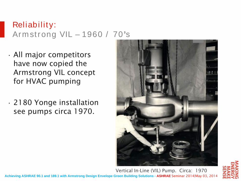
Reliability:Armstrong VIL – 1960 / 70’s
• All major competitors have now copied the Armstrong VIL concept for HVAC pumping
• 2180 Yonge installation see pumps circa 1970.
Still relevant for present day –Add Sustainability concerns
Vertical In-Line (VIL) Pump. Circa: 1970
Achieving ASHRAE 90.1 and 189.1 with Armstrong Design Envelope Green Building Solutions - ASHRAE Seminar 2014|May 03, 2014
Reliability
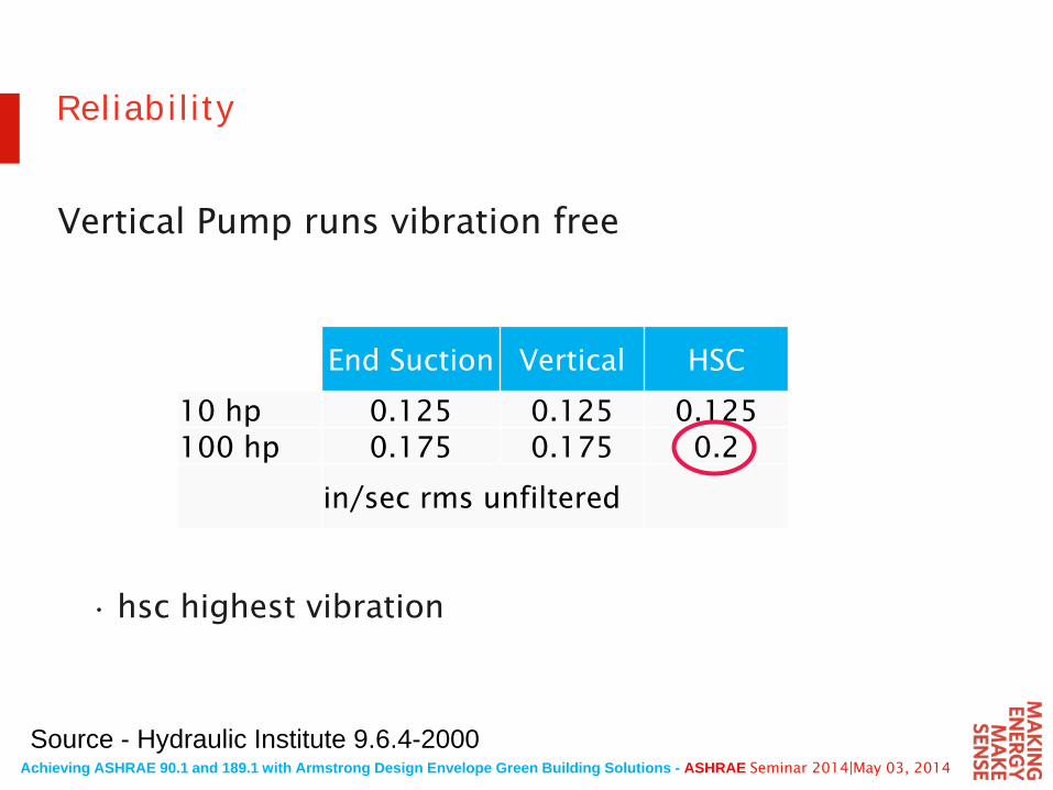
Vertical Pump runs vibration free
• hsc highest vibration
Source - Hydraulic Institute 9.6.4-2000
End Suction Vertical HSC
10 hp 0.125 0.125 0.125100 hp 0.175 0.175 0.2
in/sec rms unfiltered
Achieving ASHRAE 90.1 and 189.1 with Armstrong Design Envelope Green Building Solutions - ASHRAE Seminar 2014|May 03, 2014
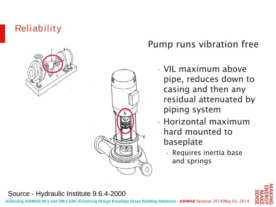
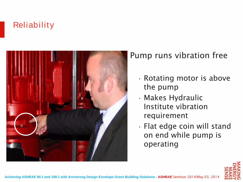
ReliabilityPump runs vibration free
• VIL maximum above pipe, reduces down to casing and then any residual attenuated by piping system
• Horizontal maximum hard mounted to baseplate • Requires inertia base
and springs
Source - Hydraulic Institute 9.6.4-2000
Achieving ASHRAE 90.1 and 189.1 with Armstrong Design Envelope Green Building Solutions - ASHRAE Seminar 2014|May 03, 2014
Reliability
Pump runs vibration free
• Rotating motor is above the pump
• Makes Hydraulic Institute vibration requirement
• Flat edge coin will stand on end while pump is operating
Achieving ASHRAE 90.1 and 189.1 with Armstrong Design Envelope Green Building Solutions - ASHRAE Seminar 2014|May 03, 2014
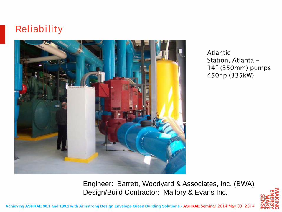
Reliability
Atlantic Station, Atlanta –14” (350mm) pumps 450hp (335kW)
Engineer: Barrett, Woodyard & Associates, Inc. (BWA)Design/Build Contractor: Mallory & Evans Inc.
Achieving ASHRAE 90.1 and 189.1 with Armstrong Design Envelope Green Building Solutions - ASHRAE Seminar 2014|May 03, 2014
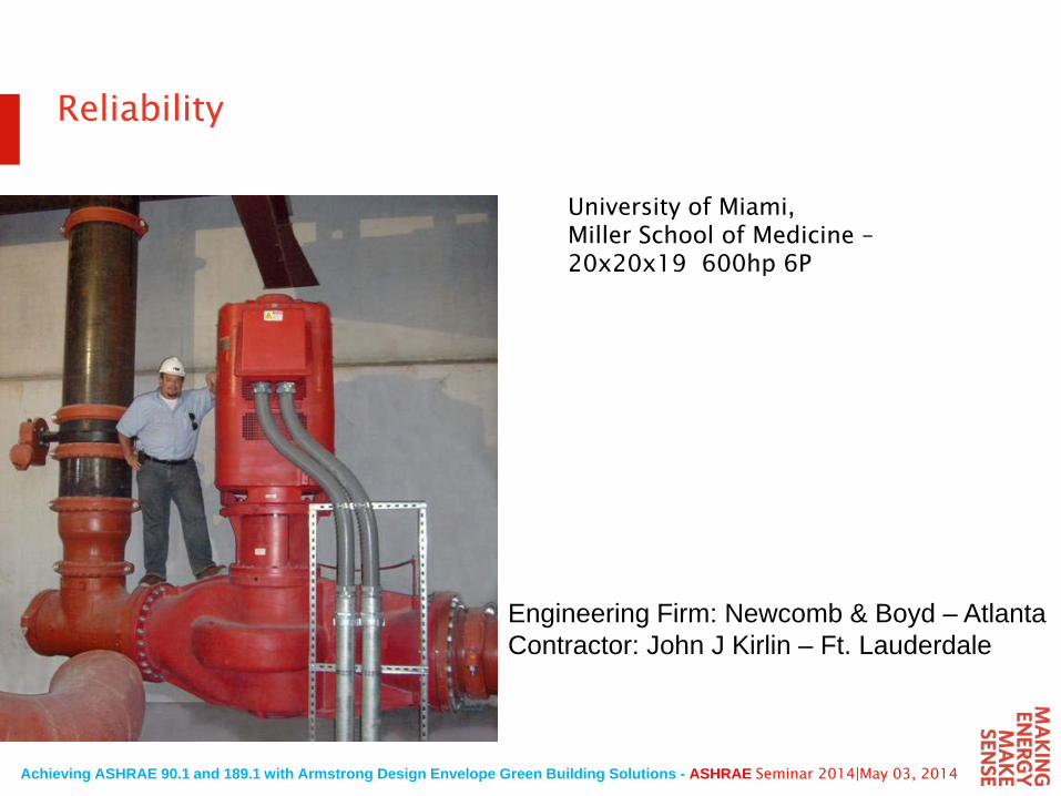
Reliability
University of Miami, Miller School of Medicine –20x20x19 600hp 6P
Engineering Firm: Newcomb & Boyd – AtlantaContractor: John J Kirlin – Ft. Lauderdale
Achieving ASHRAE 90.1 and 189.1 with Armstrong Design Envelope Green Building Solutions - ASHRAE Seminar 2014|May 03, 2014
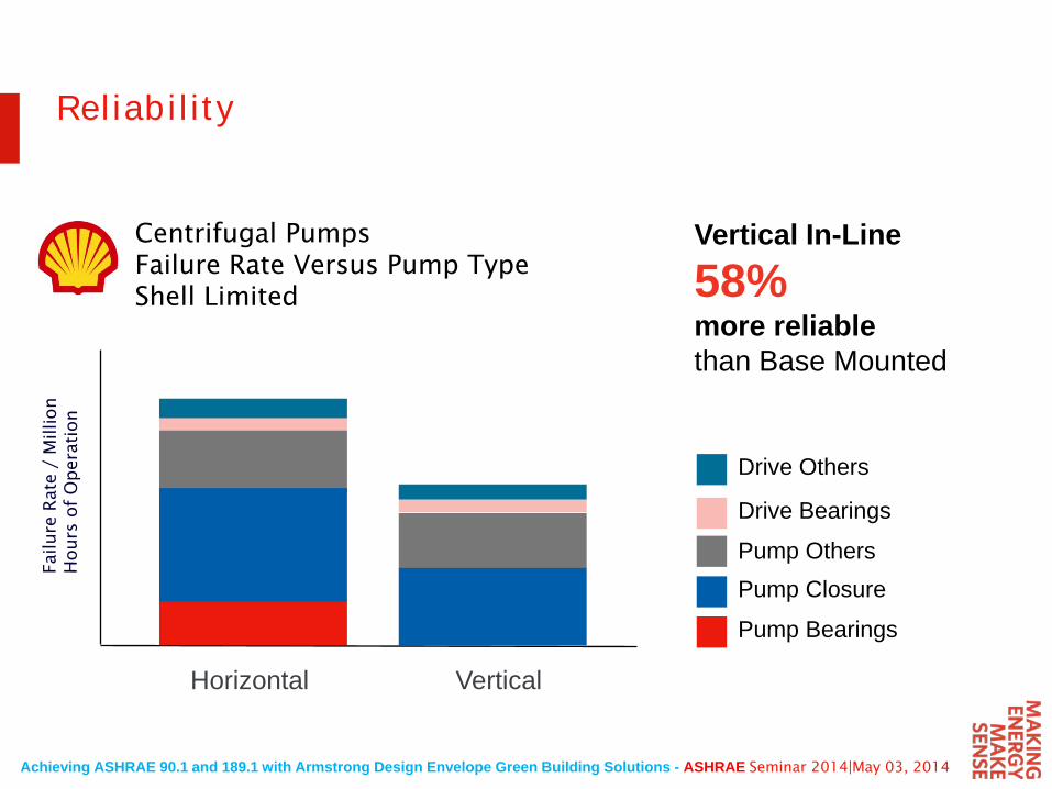
Drive Others
Centrifugal PumpsFailure Rate Versus Pump Type Shell Limited
150 –
100–
50 –
0 –
Horizontal Vertical
Vertical In-Line
58%more reliablethan Base Mounted
Reliability
Pump Bearings
Pump ClosurePump Others
Drive Bearings
Achieving ASHRAE 90.1 and 189.1 with Armstrong Design Envelope Green Building Solutions - ASHRAE Seminar 2014|May 03, 2014
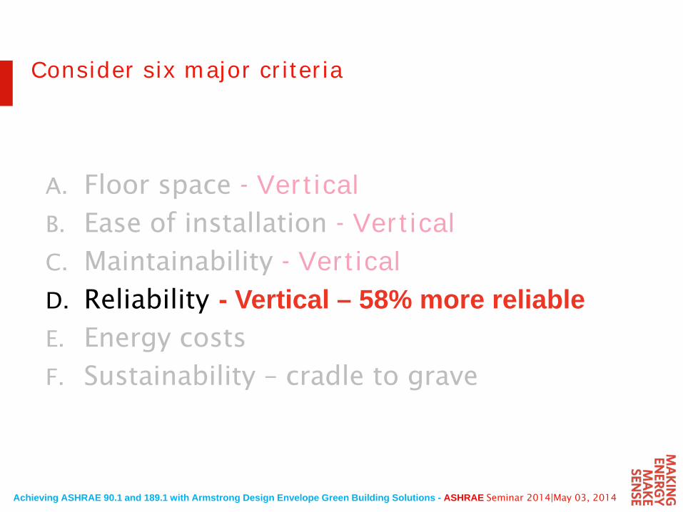
A. Floor space - VerticalB. Ease of installation - VerticalC. Maintainability - VerticalD. Reliability
E. Energy costs
F. Sustainability – cradle to grave
Consider six major criteria
- Vertical – 58% more reliable
Achieving ASHRAE 90.1 and 189.1 with Armstrong Design Envelope Green Building Solutions - ASHRAE Seminar 2014|May 03, 2014
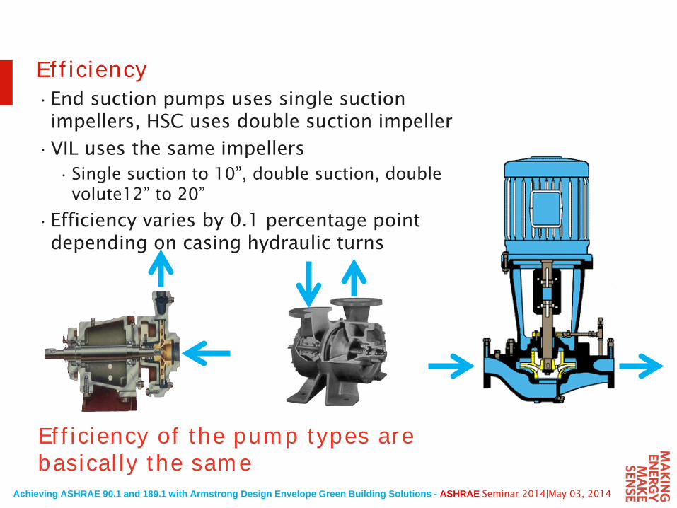
•End suction pumps uses single suction impellers, HSC uses double suction impeller
•VIL uses the same impellers • Single suction to 10”, double suction, double
volute12” to 20”
•Efficiency varies by 0.1 percentage point depending on casing hydraulic turns
Efficiency of the pump types are basically the same
Efficiency
Achieving ASHRAE 90.1 and 189.1 with Armstrong Design Envelope Green Building Solutions - ASHRAE Seminar 2014|May 03, 2014
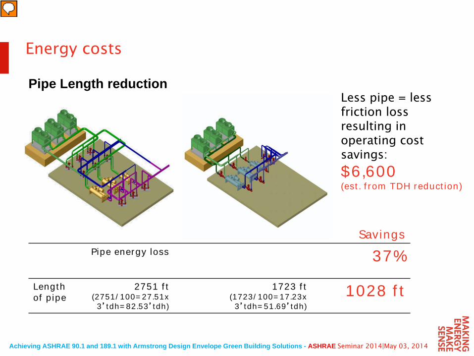
Less pipe = less friction lossresulting in operating cost savings:
$6,600(est. from TDH reduction)
SavingsPipe energy loss 37%
Length of pipe
2751 ft(2751/100=27.51x3’tdh=82.53’tdh)
1723 ft(1723/100=17.23x3’tdh=51.69’tdh)
1028 ft
Energy costs
Pipe Length reduction
Achieving ASHRAE 90.1 and 189.1 with Armstrong Design Envelope Green Building Solutions - ASHRAE Seminar 2014|May 03, 2014
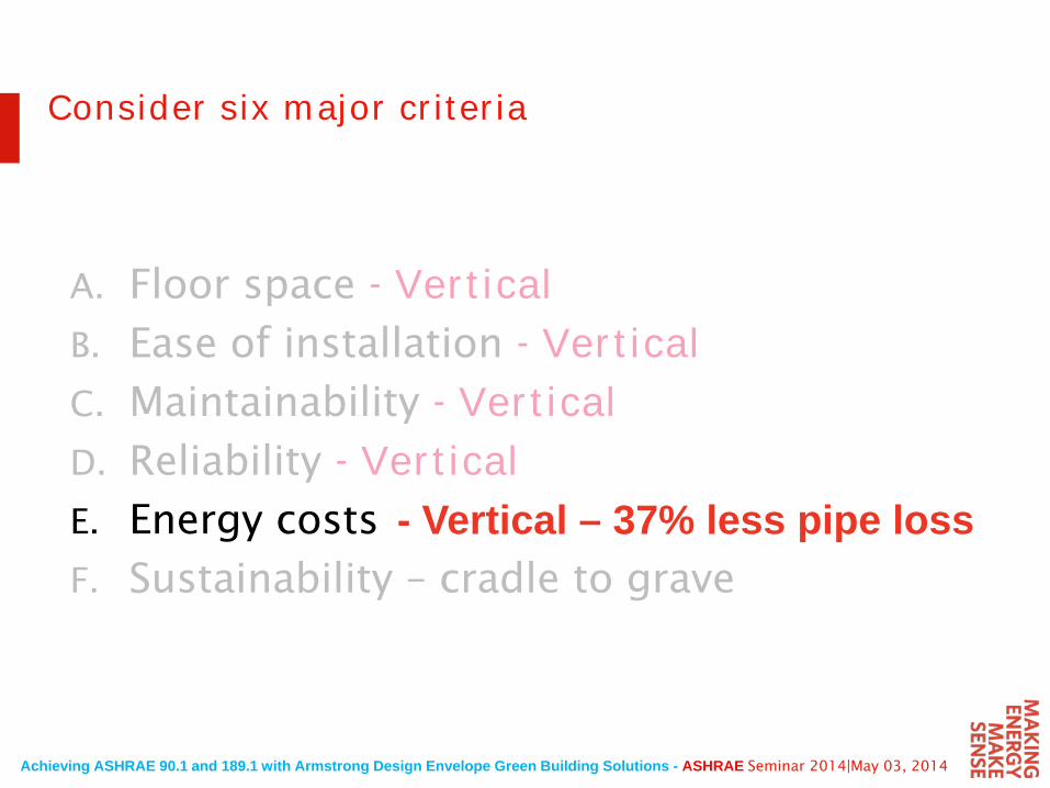
A. Floor space - VerticalB. Ease of installation - VerticalC. Maintainability - VerticalD. Reliability - VerticalE. Energy costs
F. Sustainability – cradle to grave
Consider six major criteria
- Vertical – 37% less pipe loss
Achieving ASHRAE 90.1 and 189.1 with Armstrong Design Envelope Green Building Solutions - ASHRAE Seminar 2014|May 03, 2014
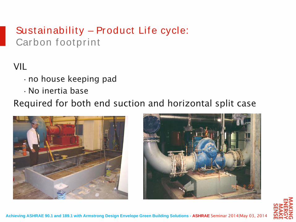
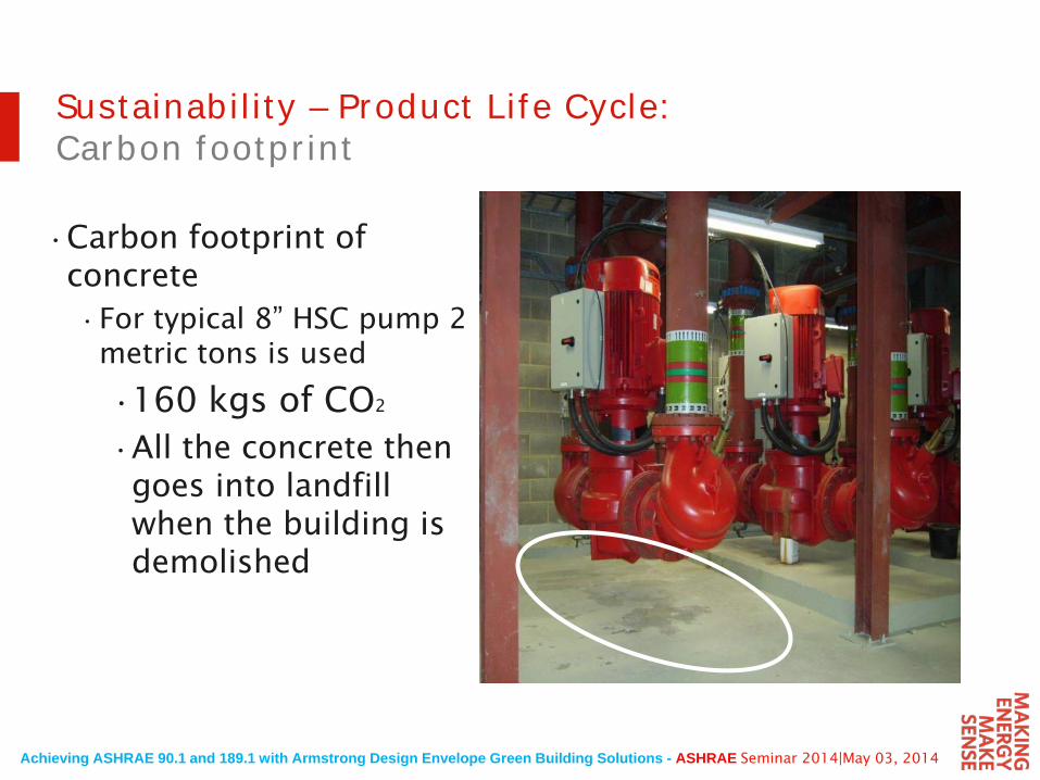
Sustainability – Product Life cycle:Carbon footprint
VIL•no house keeping pad
•No inertia base
Required for both end suction and horizontal split case
Achieving ASHRAE 90.1 and 189.1 with Armstrong Design Envelope Green Building Solutions - ASHRAE Seminar 2014|May 03, 2014
Sustainability – Product Life Cycle:Carbon footprint
•Carbon footprint of concrete •For typical 8” HSC pump 2
metric tons is used
•160 kgs of CO2
•All the concrete then goes into landfill when the building is demolished
Achieving ASHRAE 90.1 and 189.1 with Armstrong Design Envelope Green Building Solutions - ASHRAE Seminar 2014|May 03, 2014
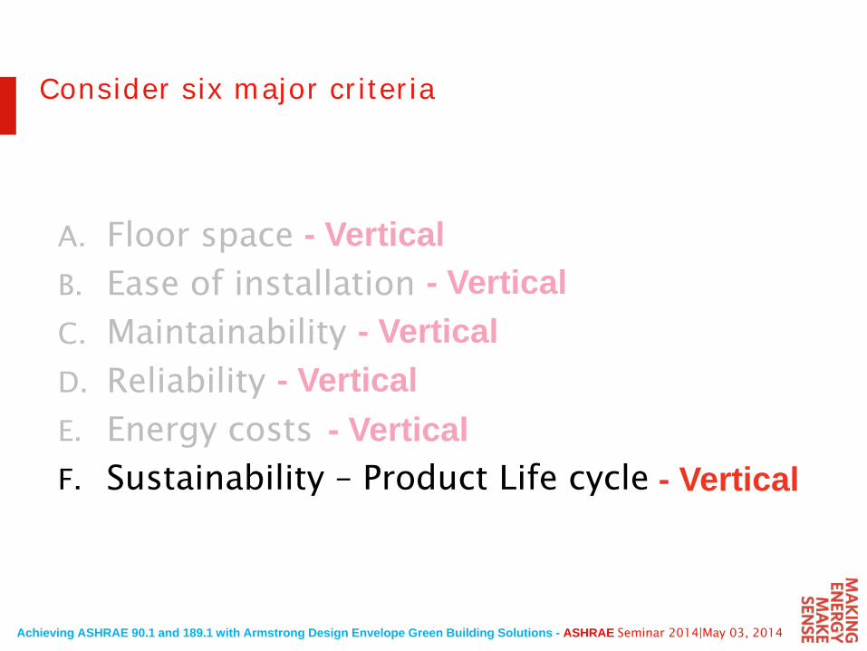
A. Floor space
B. Ease of installation
C. Maintainability
D. Reliability
E. Energy costs
F. Sustainability – Product Life cycle
Consider six major criteria
- Vertical- Vertical
- Vertical- Vertical
- Vertical- Vertical
Achieving ASHRAE 90.1 and 189.1 with Armstrong Design Envelope Green Building Solutions - ASHRAE Seminar 2014|May 03, 2014
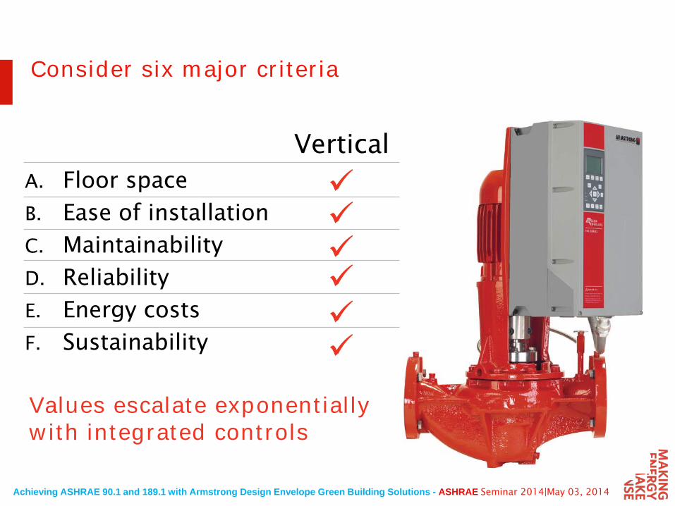
Values escalate exponentially with integrated controls
Consider six major criteria
A. Floor space
B. Ease of installation
C. Maintainability
D. Reliability
E. Energy costs
F. Sustainability
Vertical
Achieving ASHRAE 90.1 and 189.1 with Armstrong Design Envelope Green Building Solutions - ASHRAE Seminar 2014|May 03, 2014
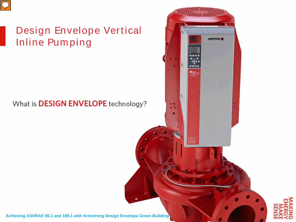
Design Envelope Vertical Inline Pumping
Achieving ASHRAE 90.1 and 189.1 with Armstrong Design Envelope Green Building Solutions - ASHRAE Seminar 2014|May 03, 2014
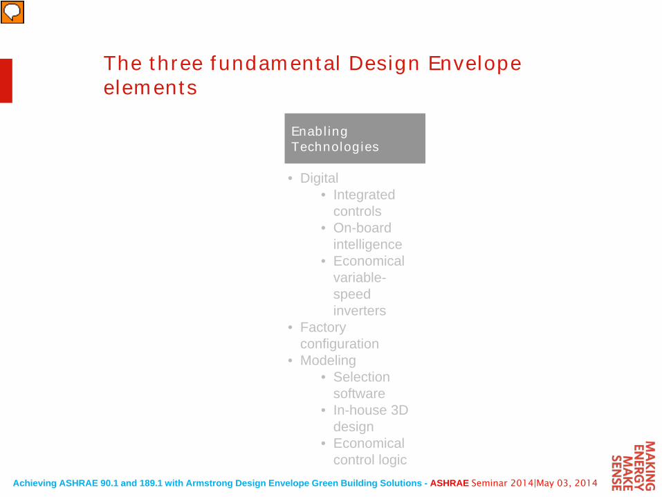
The three fundamental Design Envelope elements
• Digital• Integrated
controls• On-board
intelligence• Economical
variable-speed inverters
• Factory configuration
• Modeling• Selection
software• In-house 3D
design• Economical
control logic
Enabling Technologies
Achieving ASHRAE 90.1 and 189.1 with Armstrong Design Envelope Green Building Solutions - ASHRAE Seminar 2014|May 03, 2014
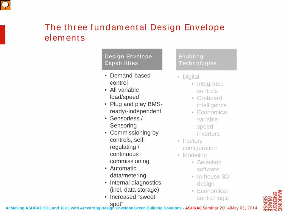
The three fundamental Design Envelope elements
• Demand-based control
• All variable load/speed
• Plug and play BMS-ready/-independent
• Sensorless / Sensoring
• Commissioning by controls, self-regulating / continuous commissioning
• Automatic data/metering
• Internal diagnostics (incl. data storage)
• Increased “sweet spot”
Design Envelope Capabilities
• Digital• Integrated
controls• On-board
intelligence• Economical
variable-speed inverters
• Factory configuration
• Modeling• Selection
software• In-house 3D
design• Economical
control logic
Enabling Technologies
Achieving ASHRAE 90.1 and 189.1 with Armstrong Design Envelope Green Building Solutions - ASHRAE Seminar 2014|May 03, 2014
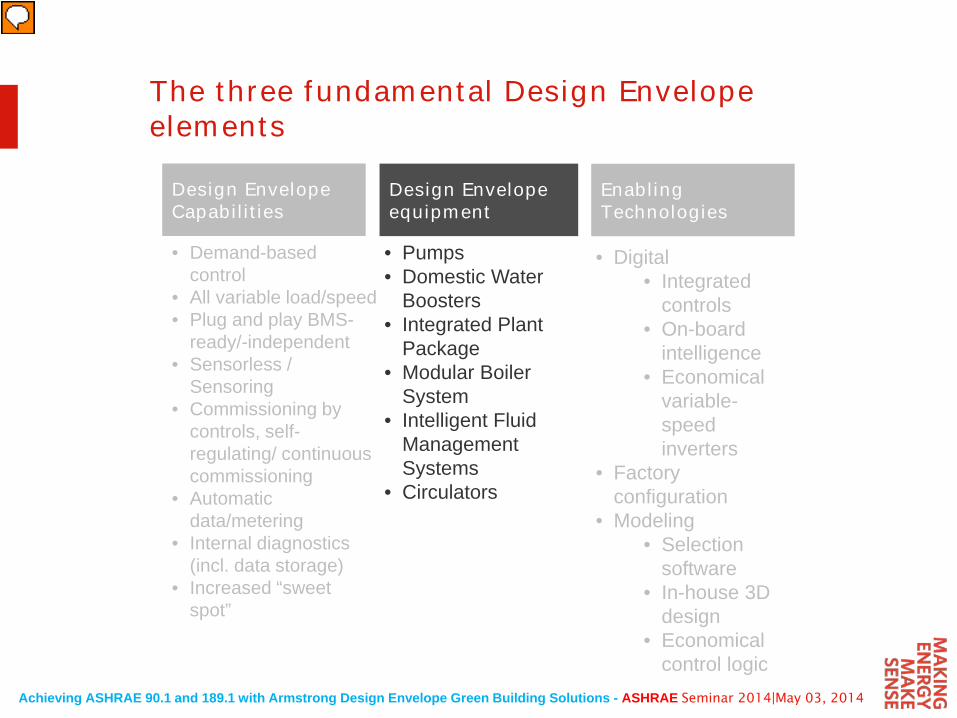
The three fundamental Design Envelope elements
• Pumps• Domestic Water
Boosters• Integrated Plant
Package• Modular Boiler
System• Intelligent Fluid
Management Systems
• Circulators
Design Envelope equipment
• Digital• Integrated
controls• On-board
intelligence• Economical
variable-speed inverters
• Factory configuration
• Modeling• Selection
software• In-house 3D
design• Economical
control logic
Enabling Technologies
• Demand-based control
• All variable load/speed• Plug and play BMS-
ready/-independent• Sensorless /
Sensoring• Commissioning by
controls, self-regulating/ continuous commissioning
• Automatic data/metering
• Internal diagnostics (incl. data storage)
• Increased “sweet spot”
Design Envelope Capabilities
Achieving ASHRAE 90.1 and 189.1 with Armstrong Design Envelope Green Building Solutions - ASHRAE Seminar 2014|May 03, 2014
London Heathrow
Los Angeles
Bahrain
Toronto Canada
Berlin Germany10%-60% of design load 90% of the time
Worldwide
Design Envelope selection methodHVAC is a global part-load industry
Achieving ASHRAE 90.1 and 189.1 with Armstrong Design Envelope Green Building Solutions - ASHRAE Seminar 2014|May 03, 2014
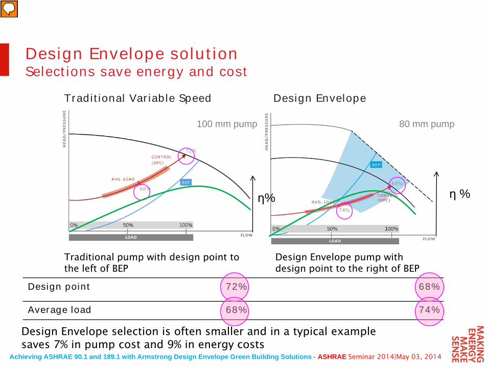
Traditional pump with design point to the left of BEP
Design Envelope pump with design point to the right of BEP
Design Envelope selection is often smaller and in a typical example saves 7% in pump cost and 9% in energy costs
Design point 72% 68%
Average load 68% 74%
100 mm pump 80 mm pump
Traditional Variable Speed Design Envelope
η %η%
Design Envelope solutionSelections save energy and cost
Achieving ASHRAE 90.1 and 189.1 with Armstrong Design Envelope Green Building Solutions - ASHRAE Seminar 2014|May 03, 2014
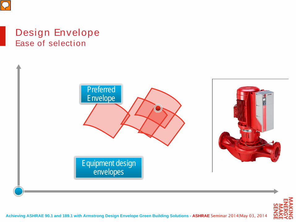
Equipment design envelopes
Preferred Envelope
Design EnvelopeEase of selection
Achieving ASHRAE 90.1 and 189.1 with Armstrong Design Envelope Green Building Solutions - ASHRAE Seminar 2014|May 03, 2014
Take the Load Off
Achieving ASHRAE 90.1 and 189.1 with Armstrong Design Envelope Green Building Solutions - ASHRAE Seminar 2014|May 03, 2014
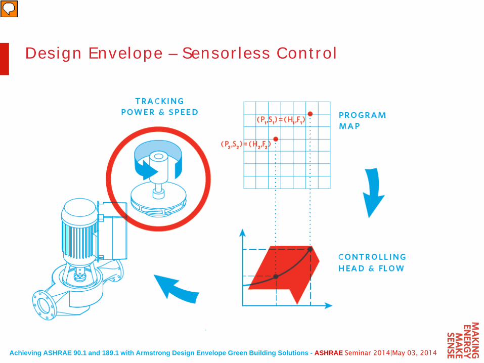
Design Envelope – Sensorless Control
Achieving ASHRAE 90.1 and 189.1 with Armstrong Design Envelope Green Building Solutions - ASHRAE Seminar 2014|May 03, 2014
Hea
d
Flow
Pow
er
12
S1
S2
Original System Curve
S1 System Curve
S2 System Curve
P1P2
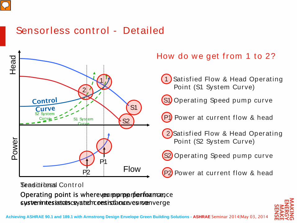
Operating point is wherever pump performance curve intersects system resistance curve
TraditionalSensorless ControlOperating point is where pump performance, system resistance and control curves converge
1 Satisfied Flow & Head Operating Point (S1 System Curve)
P1 Power at current flow & head
S1 Operating Speed pump curve
2 Satisfied Flow & Head Operating Point (S2 System Curve)
S2 Operating Speed pump curve
P2 Power at current flow & head
How do we get from 1 to 2?
Sensorless control - Detailed
Achieving ASHRAE 90.1 and 189.1 with Armstrong Design Envelope Green Building Solutions - ASHRAE Seminar 2014|May 03, 2014
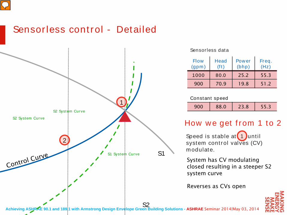
Original System Curve
System has CV modulating closed resulting in a steeper S2 system curve
Speed is stable at 1 until system control valves (CV) modulate.
1
2
S1
S2
S1 System Curve
S2 System Curve
Reverses as CVs open
Flow (gpm)
Head (ft)
Power (bhp)
Freq.(Hz)
1000 80.0 25.2 55.3
900 70.9 19.8 51.2
Constant speed900 88.0 23.8 55.3
Sensorless data
How we get from 1 to 2S2 System Curve
Sensorless control - Detailed
Achieving ASHRAE 90.1 and 189.1 with Armstrong Design Envelope Green Building Solutions - ASHRAE Seminar 2014|May 03, 2014
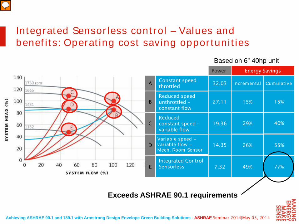
Integrated Sensorless control – Values and benefits: Operating cost saving opportunities
Power Energy Savings
32.03 Incremental CumulativeConstant speed throttled
Reduced speed unthrottled –constant flow
Reduced constant speed –variable flow
Variable speed –variable flow –Mech. Room Sensor
Integrated Control Sensorless
27.11
19.36
7.32
14.35
15%
29%
49%
26%
15%
40%
77%
55%
A
B
C
D
E
Based on 6” 40hp unit
Exceeds ASHRAE 90.1 requirements
Achieving ASHRAE 90.1 and 189.1 with Armstrong Design Envelope Green Building Solutions - ASHRAE Seminar 2014|May 03, 2014
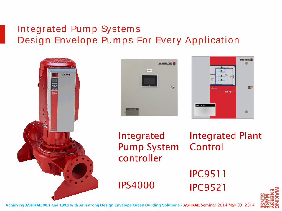
Integrated Pump SystemsDesign Envelope Pumps For Every Application
Integrated Plant Control
IPC9511
IPC9521
Integrated Pump System controller
IPS4000
ARMSTRONG
Achieving ASHRAE 90.1 and 189.1 with Armstrong Design Envelope Green Building Solutions - ASHRAE Seminar 2014|May 03, 2014
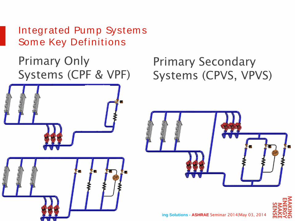
Integrated Pump SystemsSome Key Definitions
Primary Only Systems (CPF & VPF)
Primary Secondary Systems (CPVS, VPVS)
Achieving ASHRAE 90.1 and 189.1 with Armstrong Design Envelope Green Building Solutions - ASHRAE Seminar 2014|May 03, 2014
Integrated Pump SystemsObjectives
•Occupant Comfort
•Energy Savings
•2 way or 3 way valves
•Pumps provide a head pressure for valve authority on flow control
During part load operation
•Reduce pump energy with variable flow and pump speed
•Improve system delta T for performance of other equipment
Achieving ASHRAE 90.1 and 189.1 with Armstrong Design Envelope Green Building Solutions - ASHRAE Seminar 2014|May 03, 2014
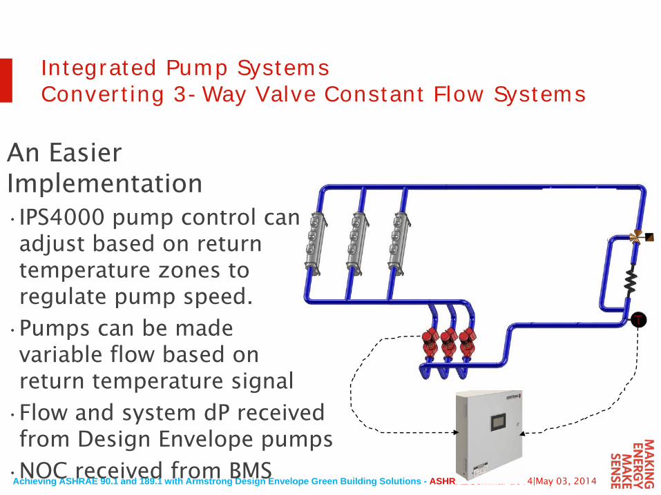
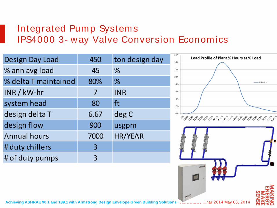
Integrated Pump SystemsConverting 3-Way Valve Constant Flow Systems
An Easier Implementation•IPS4000 pump control can adjust based on return temperature zones to regulate pump speed.
•Pumps can be made variable flow based on return temperature signal
•Flow and system dP received from Design Envelope pumps
•NOC received from BMS
Achieving ASHRAE 90.1 and 189.1 with Armstrong Design Envelope Green Building Solutions - ASHRAE Seminar 2014|May 03, 2014
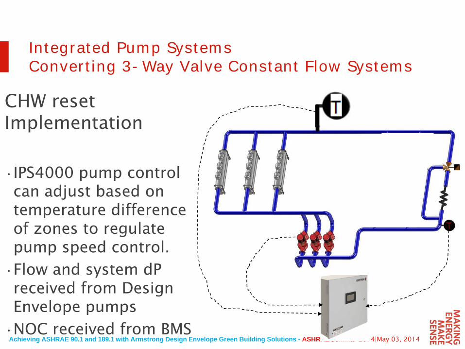
Integrated Pump SystemsConverting 3-Way Valve Constant Flow Systems
CHW reset Implementation
•IPS4000 pump control can adjust based on temperature difference of zones to regulate pump speed control.
•Flow and system dPreceived from Design Envelope pumps
•NOC received from BMS
Achieving ASHRAE 90.1 and 189.1 with Armstrong Design Envelope Green Building Solutions - ASHRAE Seminar 2014|May 03, 2014
Integrated Pump SystemsIPS4000 3-way Valve Conversion Economics
Design Day Load 450 ton design day% ann avg load 45 %% delta T maintained 80% %INR / kW-hr 7 INRsystem head 80 ftdesign delta T 6.67 deg Cdesign flow 900 usgpmAnnual hours 7000 HR/YEAR# duty chillers 3# of duty pumps 3
Achieving ASHRAE 90.1 and 189.1 with Armstrong Design Envelope Green Building Solutions - ASHRAE Seminar 2014|May 03, 2014
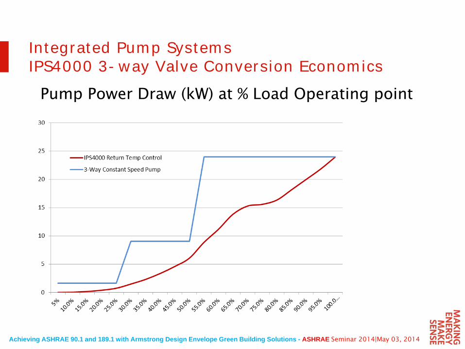
Integrated Pump SystemsIPS4000 3-way Valve Conversion Economics
Pump Power Draw (kW) at % Load Operating point
Achieving ASHRAE 90.1 and 189.1 with Armstrong Design Envelope Green Building Solutions - ASHRAE Seminar 2014|May 03, 2014
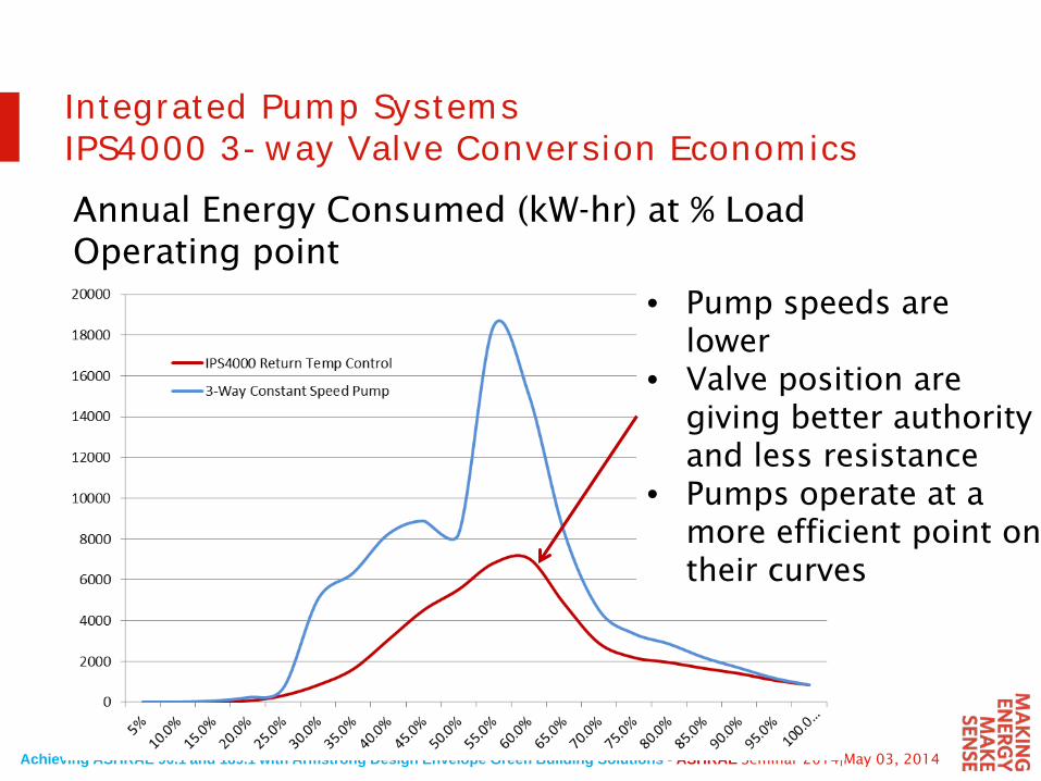
Integrated Pump SystemsIPS4000 3-way Valve Conversion EconomicsAnnual Energy Consumed (kW-hr) at % Load Operating point
• Pump speeds are lower
• Valve position are giving better authority and less resistance
• Pumps operate at a more efficient point on their curves
Achieving ASHRAE 90.1 and 189.1 with Armstrong Design Envelope Green Building Solutions - ASHRAE Seminar 2014|May 03, 2014
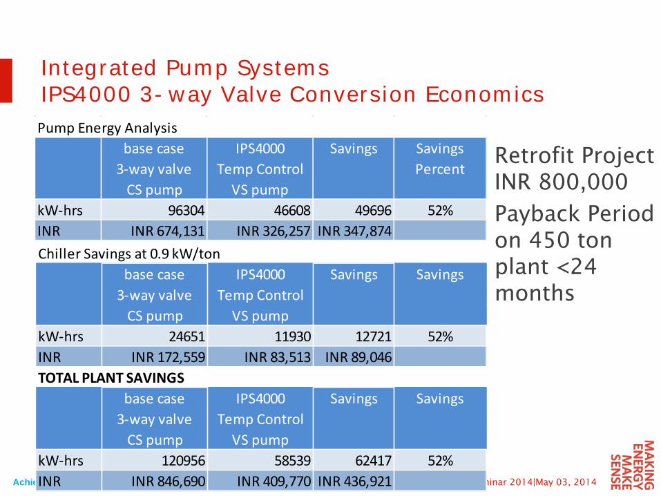
Integrated Pump SystemsIPS4000 3-way Valve Conversion EconomicsPump Energy Analysis
base case IPS4000 Savings Savings3-way valve Temp Control Percent
CS pump VS pumpkW-hrs 96304 46608 49696 52%INR INR 674,131 INR 326,257 INR 347,874 Chiller Savings at 0.9 kW/ton
base case IPS4000 Savings Savings3-way valve Temp Control
CS pump VS pumpkW-hrs 24651 11930 12721 52%INR INR 172,559 INR 83,513 INR 89,046 TOTAL PLANT SAVINGS
base case IPS4000 Savings Savings3-way valve Temp Control
CS pump VS pumpkW-hrs 120956 58539 62417 52%INR INR 846,690 INR 409,770 INR 436,921
Retrofit Project INR 800,000
Payback Period on 450 ton plant <24 months
Achieving ASHRAE 90.1 and 189.1 with Armstrong Design Envelope Green Building Solutions - ASHRAE Seminar 2014|May 03, 2014
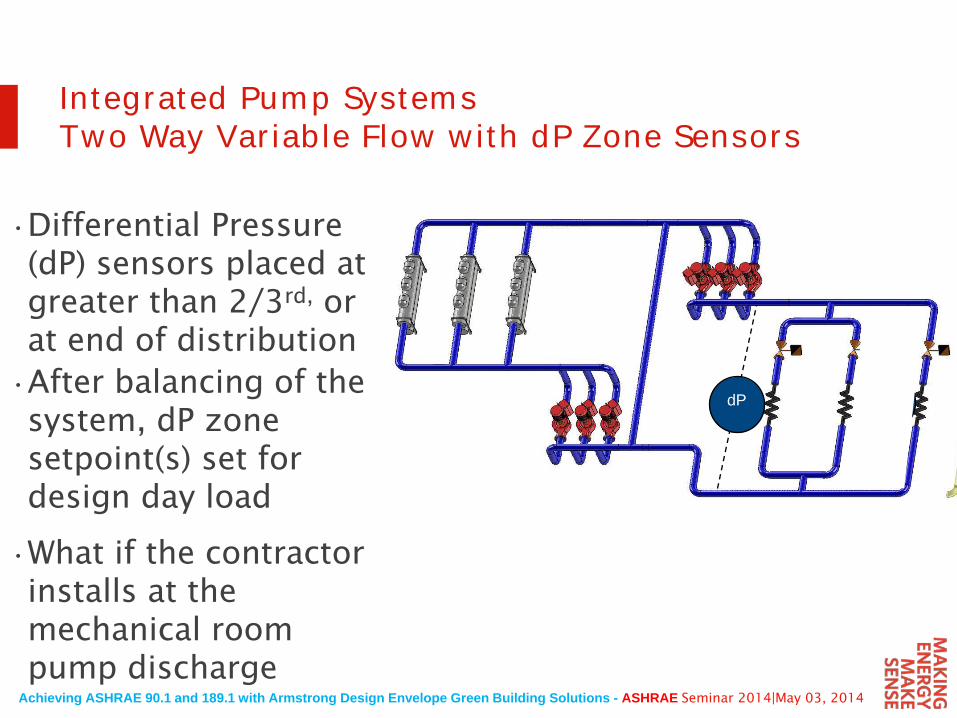
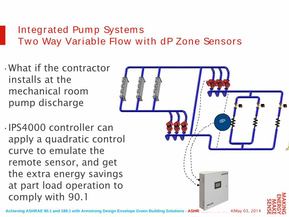
Integrated Pump SystemsTwo Way Variable Flow with dP Zone Sensors
•Differential Pressure (dP) sensors placed at greater than 2/3rd, or at end of distribution
dP•After balancing of the system, dP zone setpoint(s) set for design day load
•What if the contractor installs at the mechanical room pump discharge
dP
Achieving ASHRAE 90.1 and 189.1 with Armstrong Design Envelope Green Building Solutions - ASHRAE Seminar 2014|May 03, 2014
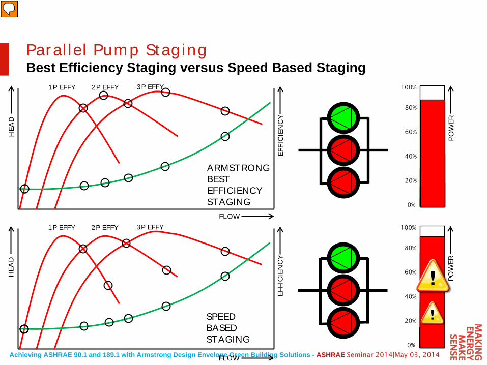
Parallel Pump StagingBest Efficiency Staging versus Speed Based Staging
0%
100%
20%
40%
60%
80%
FLOW
HEA
D
EFFI
CIEN
CY
POW
ER
1P EFFY 2P EFFY 3P EFFY
0%
100%
20%
40%
60%
80%
FLOW
HEA
D
EFFI
CIEN
CY
POW
ER
1P EFFY 2P EFFY 3P EFFY
ARMSTRONGBESTEFFICIENCYSTAGING
SPEEDBASEDSTAGING
Achieving ASHRAE 90.1 and 189.1 with Armstrong Design Envelope Green Building Solutions - ASHRAE Seminar 2014|May 03, 2014
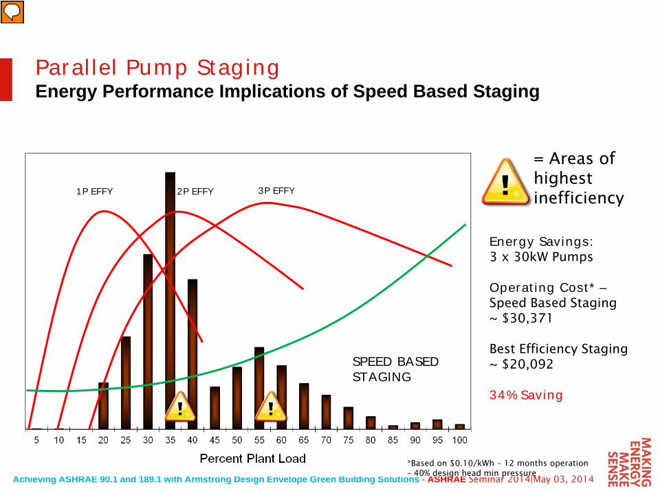
Parallel Pump StagingEnergy Performance Implications of Speed Based Staging
1P EFFY 2P EFFY 3P EFFY
SPEED BASED STAGING
Energy Savings:3 x 30kW Pumps
Operating Cost* –Speed Based Staging~ $30,371
Best Efficiency Staging~ $20,092
34% Saving
*Based on $0.10/kWh – 12 months operation – 40% design head min pressure
= Areas of highest inefficiency
Achieving ASHRAE 90.1 and 189.1 with Armstrong Design Envelope Green Building Solutions - ASHRAE Seminar 2014|May 03, 2014
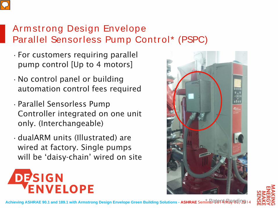
Armstrong Design EnvelopeParallel Sensorless Pump Control* (PSPC)•For customers requiring parallel
pump control [Up to 4 motors]
•No control panel or building automation control fees required
•Parallel Sensorless Pump Controller integrated on one unit only. (Interchangeable)
•dualARM units (Illustrated) are wired at factory. Single pumps will be ‘daisy-chain’ wired on site
* Patent Pending
Achieving ASHRAE 90.1 and 189.1 with Armstrong Design Envelope Green Building Solutions - ASHRAE Seminar 2014|May 03, 2014
Integrated Pump SystemsTwo Way Variable Flow with dP Zone Sensors
•What if the contractor installs at the mechanical room pump discharge
dP
•IPS4000 controller can apply a quadratic control curve to emulate the remote sensor, and get the extra energy savings at part load operation to comply with 90.1
Achieving ASHRAE 90.1 and 189.1 with Armstrong Design Envelope Green Building Solutions - ASHRAE Seminar 2014|May 03, 2014
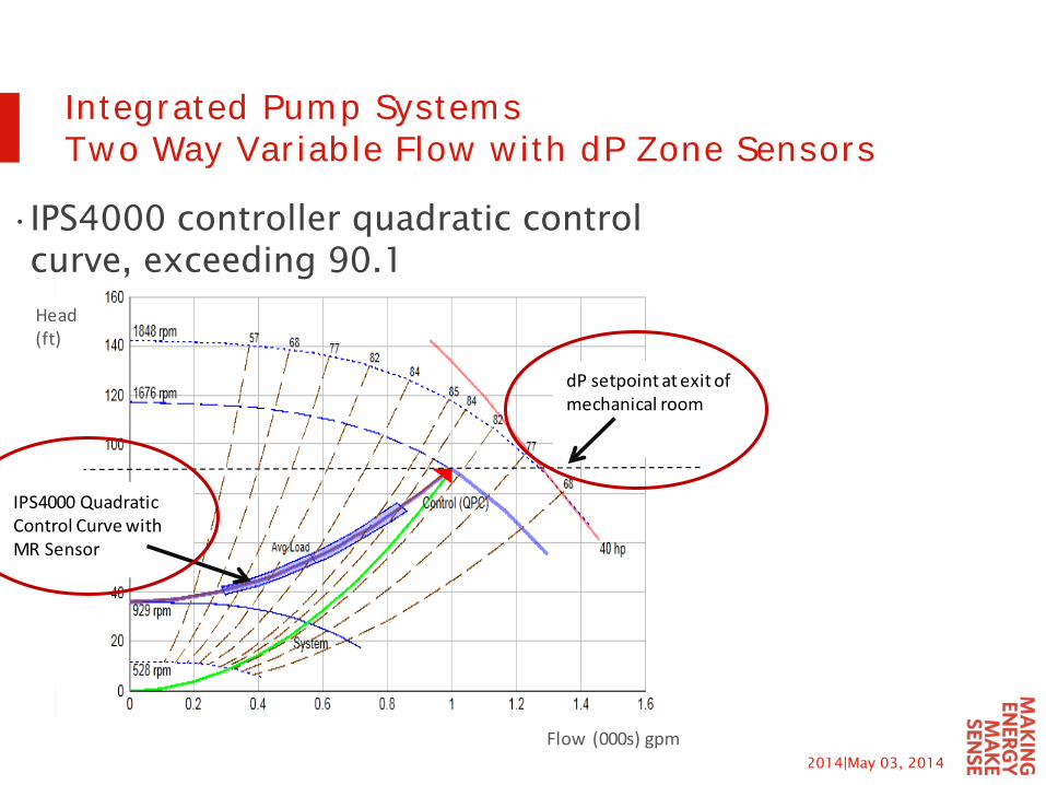
Flow (000s) gpm
Head (ft)
dP setpoint at exit of mechanical room
IPS4000 Quadratic Control Curve withMR Sensor
Integrated Pump SystemsTwo Way Variable Flow with dP Zone Sensors
•IPS4000 controller quadratic control curve, exceeding 90.1
Achieving ASHRAE 90.1 and 189.1 with Armstrong Design Envelope Green Building Solutions - ASHRAE Seminar 2014|May 03, 2014
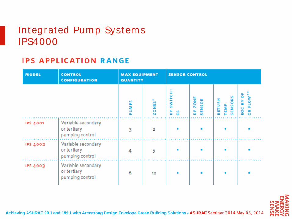
Integrated Pump SystemsIPS4000
Achieving ASHRAE 90.1 and 189.1 with Armstrong Design Envelope Green Building Solutions - ASHRAE Seminar 2014|May 03, 2014
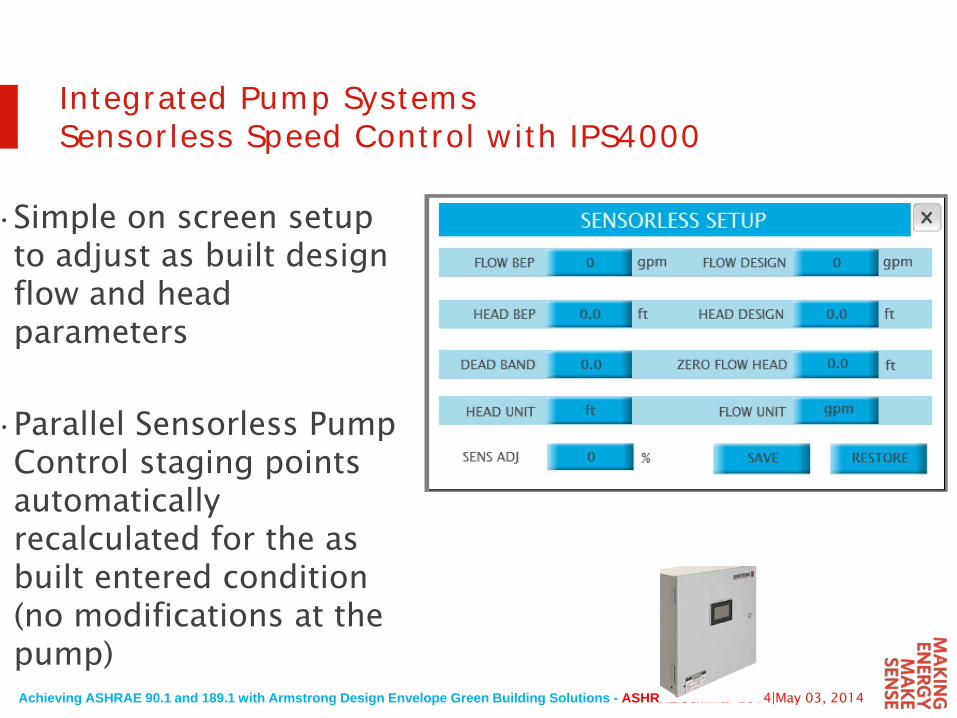
Integrated Pump SystemsSensorless Speed Control with IPS4000
•Simple on screen setup to adjust as built design flow and head parameters
•Parallel Sensorless Pump Control staging points automatically recalculated for the as built entered condition (no modifications at the pump)
Achieving ASHRAE 90.1 and 189.1 with Armstrong Design Envelope Green Building Solutions - ASHRAE Seminar 2014|May 03, 2014
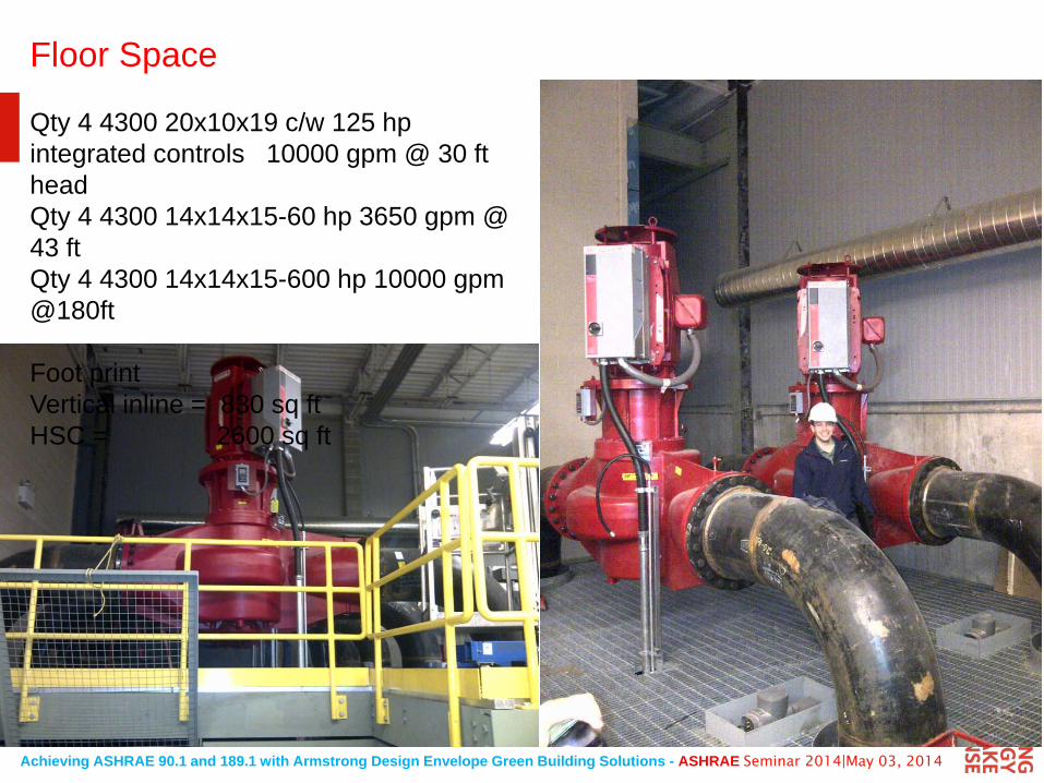
Floor Space
Qty 4 4300 20x10x19 c/w 125 hpintegrated controls 10000 gpm @ 30 ftheadQty 4 4300 14x14x15-60 hp 3650 gpm @ 43 ftQty 4 4300 14x14x15-600 hp 10000 gpm@180ft
Foot print Vertical inline = 830 sq ftHSC = 2600 sq ft
Achieving ASHRAE 90.1 and 189.1 with Armstrong Design Envelope Green Building Solutions - ASHRAE Seminar 2014|May 03, 2014
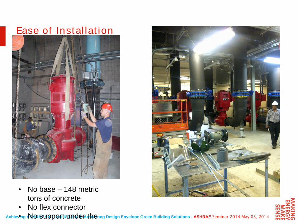
Ease of Installation
• No base – 148 metric tons of concrete
• No flex connector• No support under the
Achieving ASHRAE 90.1 and 189.1 with Armstrong Design Envelope Green Building Solutions - ASHRAE Seminar 2014|May 03, 2014
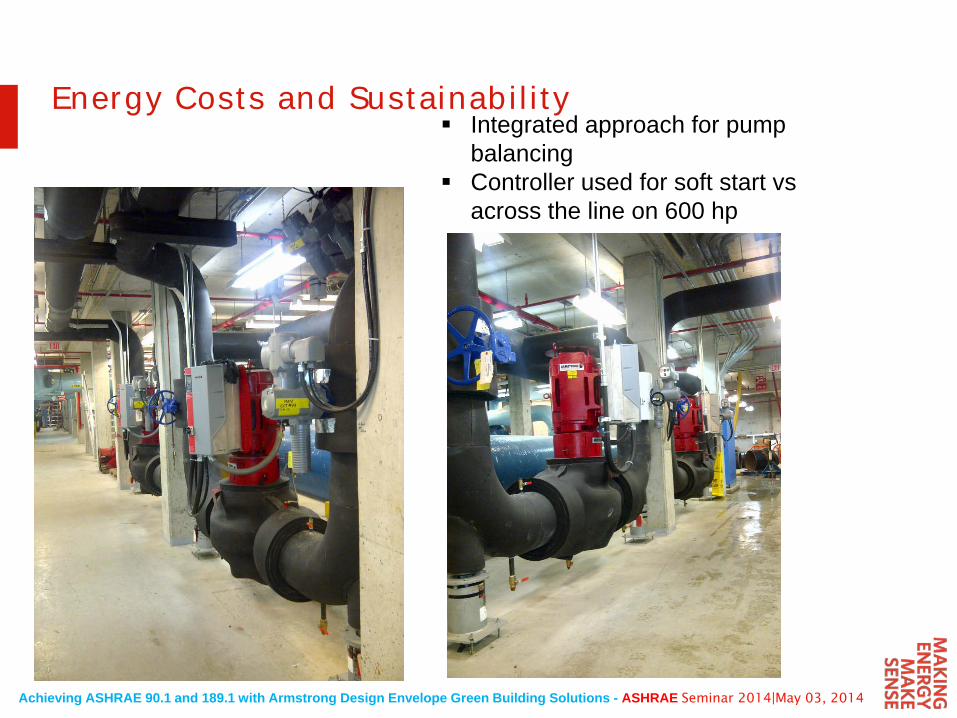
Energy Costs and Sustainability Integrated approach for pump
balancing Controller used for soft start vs
across the line on 600 hp
Achieving ASHRAE 90.1 and 189.1 with Armstrong Design Envelope Green Building Solutions - ASHRAE Seminar 2014|May 03, 2014
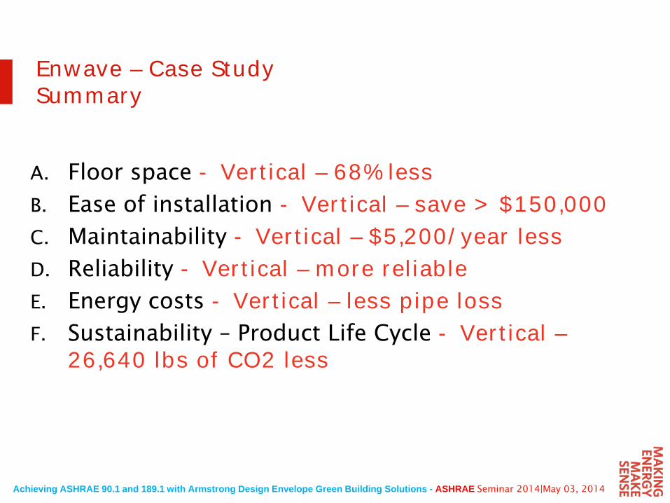
Enwave – Case StudySummary
A. Floor space - Vertical – 68% lessB. Ease of installation - Vertical – save > $150,000C. Maintainability - Vertical – $5,200/year lessD. Reliability - Vertical – more reliableE. Energy costs - Vertical – less pipe lossF. Sustainability – Product Life Cycle - Vertical –
26,640 lbs of CO2 less
Achieving ASHRAE 90.1 and 189.1 with Armstrong Design Envelope Green Building Solutions - ASHRAE Seminar 2014|May 03, 2014
Achieving 189.1 Through Integrated Plant Control
Achieving ASHRAE 90.1 and 189.1 with Armstrong Design Envelope Green Building Solutions - ASHRAE Seminar 2014|May 03, 2014
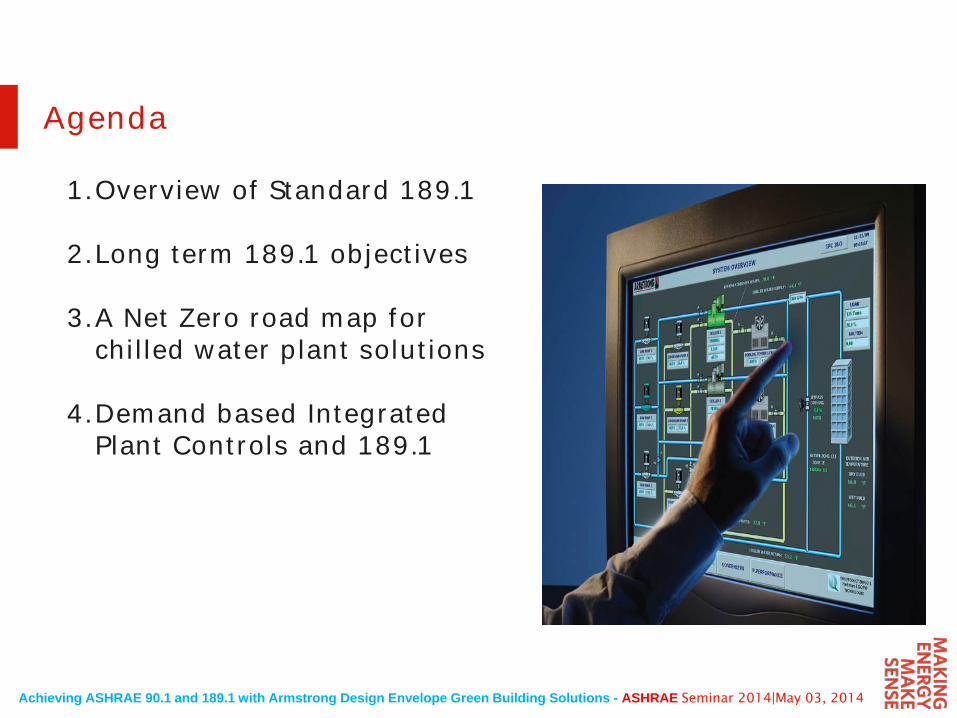
Agenda
1.Overview of Standard 189.1
2.Long term 189.1 objectives
3.A Net Zero road map for chilled water plant solutions
4.Demand based Integrated Plant Controls and 189.1
Achieving ASHRAE 90.1 and 189.1 with Armstrong Design Envelope Green Building Solutions - ASHRAE Seminar 2014|May 03, 2014
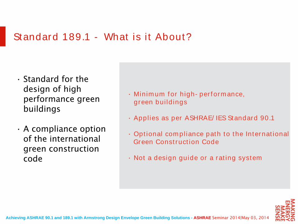
Standard 189.1 - What is it About?
• Standard for the design of high performance green buildings
• A compliance option of the international green construction code
• Minimum for high-performance, green buildings
• Applies as per ASHRAE/IES Standard 90.1
• Optional compliance path to the International Green Construction Code
• Not a design guide or a rating system
Achieving ASHRAE 90.1 and 189.1 with Armstrong Design Envelope Green Building Solutions - ASHRAE Seminar 2014|May 03, 2014
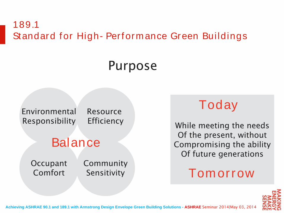
189.1 Standard for High-Performance Green Buildings
Purpose
EnvironmentalResponsibility
Resource Efficiency
OccupantComfort
CommunitySensitivity
While meeting the needsOf the present, without
Compromising the abilityOf future generations
Balance
Today
Tomorrow
Achieving ASHRAE 90.1 and 189.1 with Armstrong Design Envelope Green Building Solutions - ASHRAE Seminar 2014|May 03, 2014
189.1 Application
• Is Voluntary
• Can be adopted as law
• Draws from ASHRAE 62.1 and 90.1
• Applies to the building design, construction and life
• “prescriptive” or “performance” based
Achieving ASHRAE 90.1 and 189.1 with Armstrong Design Envelope Green Building Solutions - ASHRAE Seminar 2014|May 03, 2014
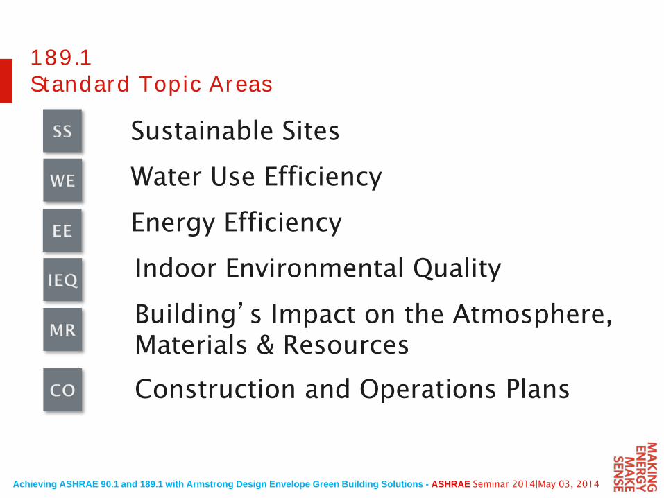
189.1Standard Topic Areas
Sustainable Sites
Water Use Efficiency
Energy Efficiency
Indoor Environmental Quality
Building’s Impact on the Atmosphere, Materials & Resources
Construction and Operations Plans
Achieving ASHRAE 90.1 and 189.1 with Armstrong Design Envelope Green Building Solutions - ASHRAE Seminar 2014|May 03, 2014
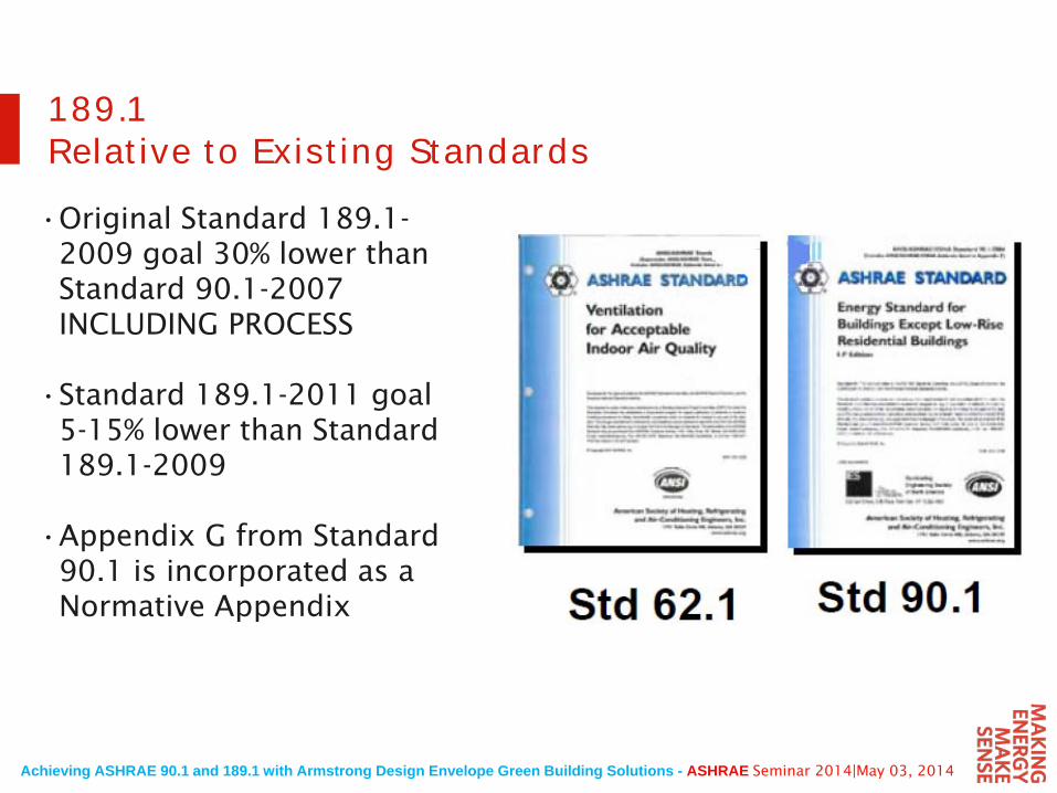
189.1Relative to Existing Standards
•Original Standard 189.1-2009 goal 30% lower than Standard 90.1-2007 INCLUDING PROCESS
•Standard 189.1-2011 goal 5-15% lower than Standard 189.1-2009
•Appendix G from Standard 90.1 is incorporated as a Normative Appendix
Achieving ASHRAE 90.1 and 189.1 with Armstrong Design Envelope Green Building Solutions - ASHRAE Seminar 2014|May 03, 2014
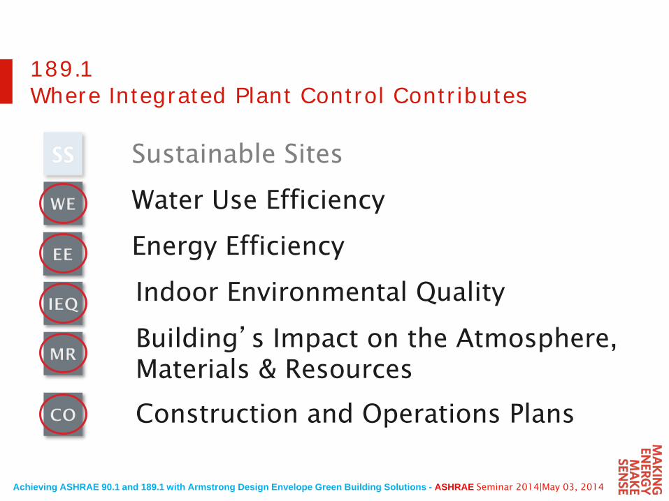
189.1Where Integrated Plant Control Contributes
Sustainable Sites
Water Use Efficiency
Energy Efficiency
Indoor Environmental Quality
Building’s Impact on the Atmosphere, Materials & Resources
Construction and Operations Plans
Achieving ASHRAE 90.1 and 189.1 with Armstrong Design Envelope Green Building Solutions - ASHRAE Seminar 2014|May 03, 2014
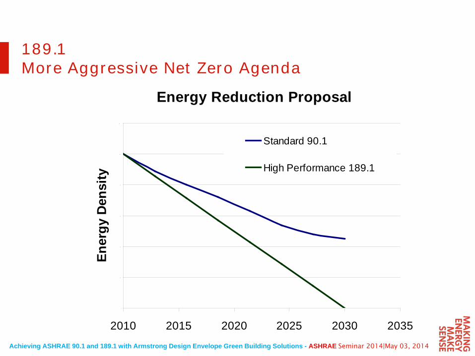
189.1More Aggressive Net Zero Agenda
Energy Reduction Proposal
0
20
40
60
80
100
120
2010 2015 2020 2025 2030 2035
Ener
gy D
ensi
ty
Standard 90.1
High Performance 189.1
Achieving ASHRAE 90.1 and 189.1 with Armstrong Design Envelope Green Building Solutions - ASHRAE Seminar 2014|May 03, 2014
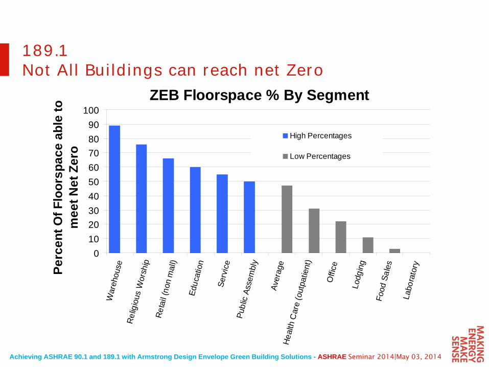
189.1Not All Buildings can reach net Zero
ZEB Floorspace % By Segment
0102030405060708090
100W
areh
ouse
Rel
igio
us W
orsh
ipR
etai
l (no
n m
all)
Educ
atio
n
Serv
ice
Publ
ic A
ssem
bly
Aver
age
Hea
lth C
are
(out
patie
nt)
Offi
ce
Lodg
ing
Food
Sal
es
Labo
rato
ryPerc
ent O
f Flo
orsp
ace
able
to
mee
t Net
Zer
o
High Percentages
Low Percentages
Achieving ASHRAE 90.1 and 189.1 with Armstrong Design Envelope Green Building Solutions - ASHRAE Seminar 2014|May 03, 2014
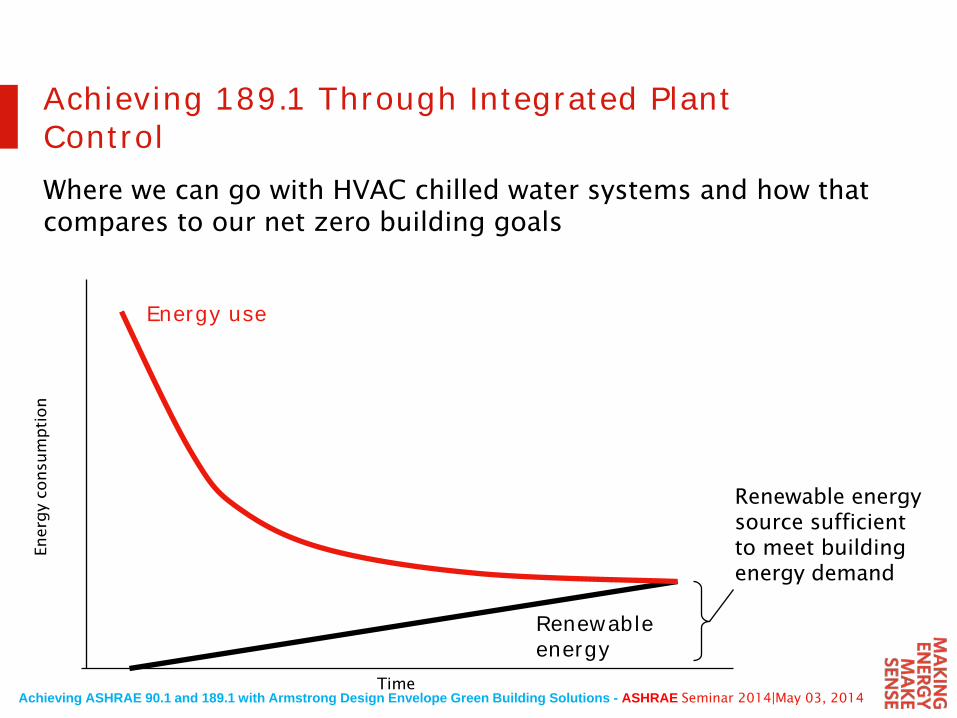
Achieving 189.1 Through Integrated Plant ControlWhere we can go with HVAC chilled water systems and how that compares to our net zero building goals
Energy use
Renewableenergy
Ener
gy
consu
mpti
on
Time
Renewable energy source sufficient to meet building energy demand
Achieving ASHRAE 90.1 and 189.1 with Armstrong Design Envelope Green Building Solutions - ASHRAE Seminar 2014|May 03, 2014
0.0
0.2
0.4
0.6
0.8
1.0
1.2
1.4
1.6
1.8
2.0
Effi
cien
cy k
W/to
n
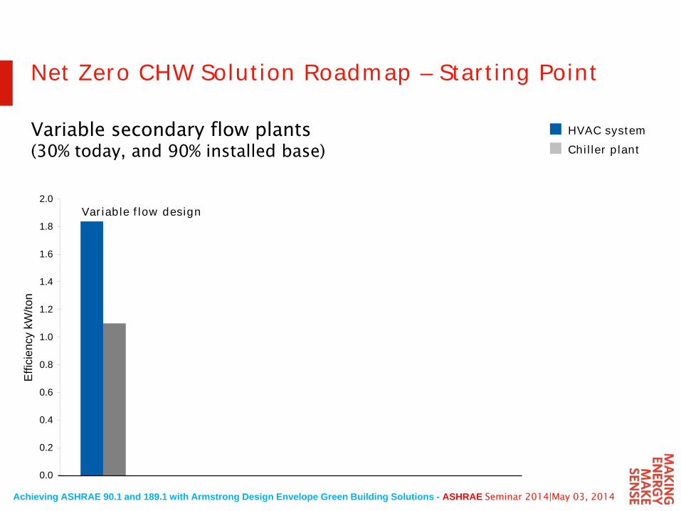
Variable flow design
HVAC systemChiller plant
Variable secondary flow plants (30% today, and 90% installed base)
Net Zero CHW Solution Roadmap – Starting Point
Achieving ASHRAE 90.1 and 189.1 with Armstrong Design Envelope Green Building Solutions - ASHRAE Seminar 2014|May 03, 2014
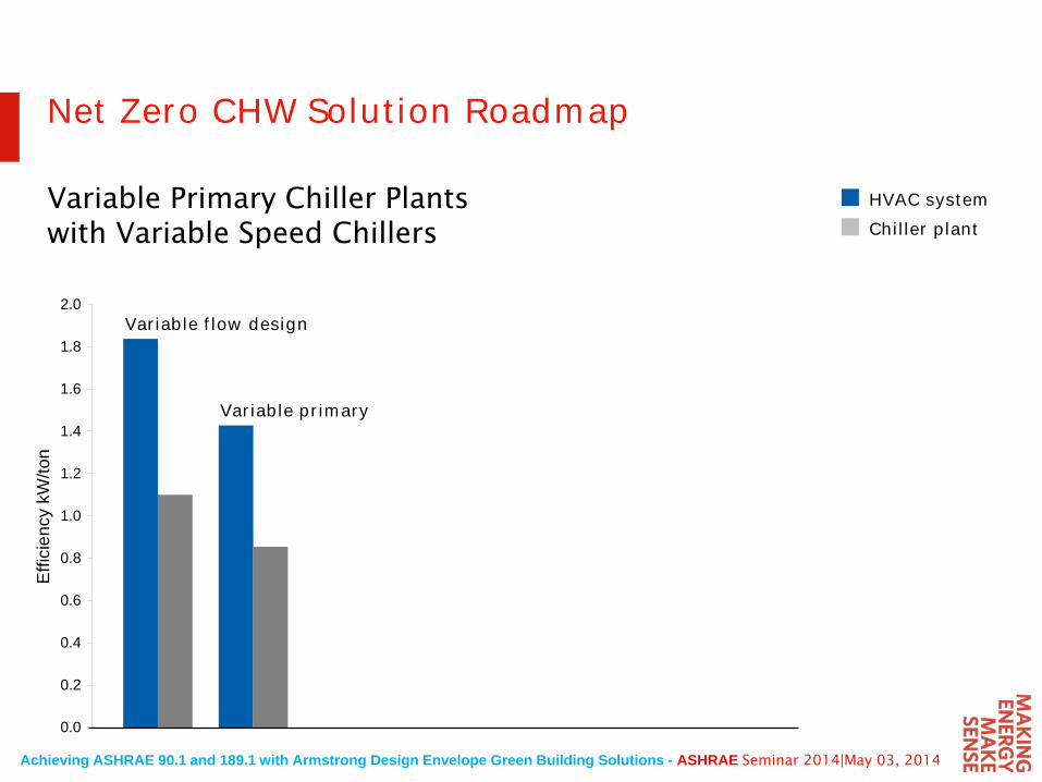
0.0
0.2
0.4
0.6
0.8
1.0
1.2
1.4
1.6
1.8
2.0
Effi
cien
cy k
W/to
n
Variable flow design
Variable primary
HVAC systemChiller plant
Net Zero CHW Solution Roadmap
Variable Primary Chiller Plants with Variable Speed Chillers
Achieving ASHRAE 90.1 and 189.1 with Armstrong Design Envelope Green Building Solutions - ASHRAE Seminar 2014|May 03, 2014
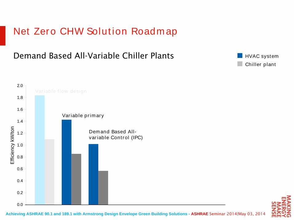
0.0
0.2
0.4
0.6
0.8
1.0
1.2
1.4
1.6
1.8
2.0
Effi
cien
cy k
W/to
n
Variable flow design
Variable primary
Demand Based All-variable Control (IPC)
HVAC systemChiller plant
Net Zero CHW Solution Roadmap
Demand Based All-Variable Chiller Plants
Achieving ASHRAE 90.1 and 189.1 with Armstrong Design Envelope Green Building Solutions - ASHRAE Seminar 2014|May 03, 2014
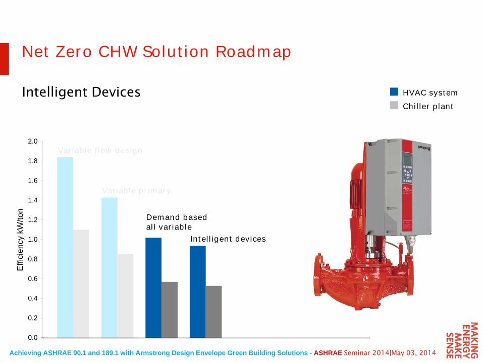
0.0
0.2
0.4
0.6
0.8
1.0
1.2
1.4
1.6
1.8
2.0
Effi
cien
cy k
W/to
n
Variable flow design
Variable primary
Demand based all variable
Intelligent devices
HVAC systemChiller plant
Net Zero CHW Solution Roadmap
Intelligent Devices
Achieving ASHRAE 90.1 and 189.1 with Armstrong Design Envelope Green Building Solutions - ASHRAE Seminar 2014|May 03, 2014
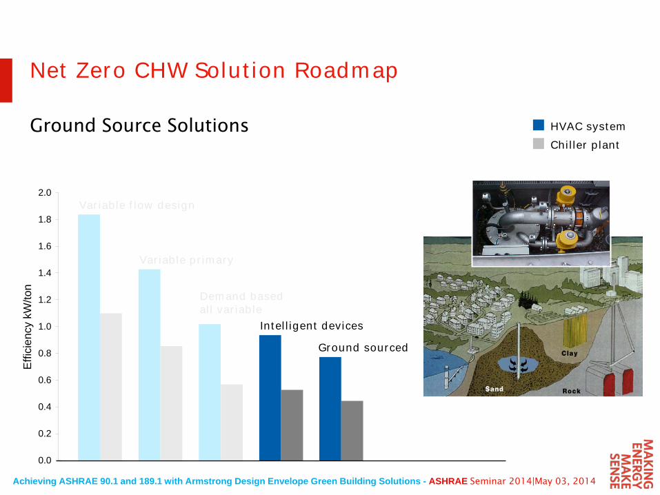
0.0
0.2
0.4
0.6
0.8
1.0
1.2
1.4
1.6
1.8
2.0
Effi
cien
cy k
W/to
n
Variable flow design
Variable primary
Demand based all variable
Intelligent devices
Ground sourced
HVAC systemChiller plant
Net Zero CHW Solution Roadmap
Ground Source Solutions
Achieving ASHRAE 90.1 and 189.1 with Armstrong Design Envelope Green Building Solutions - ASHRAE Seminar 2014|May 03, 2014
0.0
0.2
0.4
0.6
0.8
1.0
1.2
1.4
1.6
1.8
2.0
Effi
cien
cy k
W/to
n
Variable flow design
Variable primary
Demand based all variable
Intelligent devices
Ground sourced
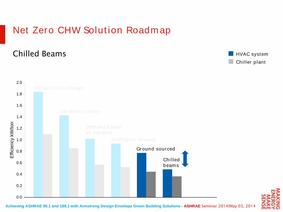
Chilled beams
HVAC systemChiller plant
Net Zero CHW Solution Roadmap
Chilled Beams
Achieving ASHRAE 90.1 and 189.1 with Armstrong Design Envelope Green Building Solutions - ASHRAE Seminar 2014|May 03, 2014
0.0
0.2
0.4
0.6
0.8
1.0
1.2
1.4
1.6
1.8
2.0
Effi
cien
cy k
W/to
n
Variable flow design
Variable primary
Demand based all variable
Intelligent devices
Ground sourced
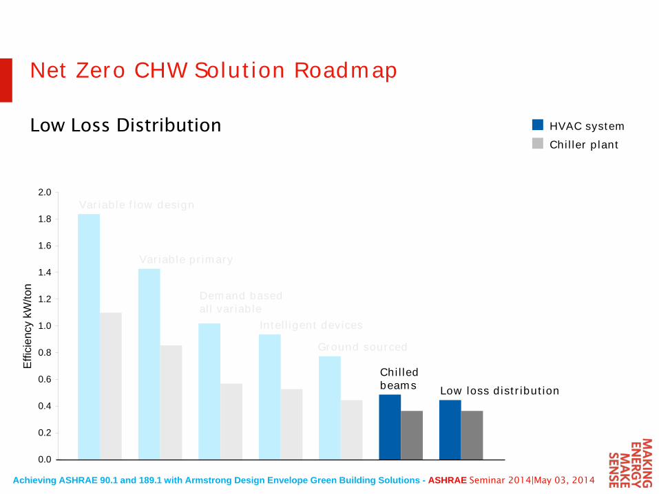
Chilled beams Low loss distribution
HVAC systemChiller plant
Net Zero CHW Solution Roadmap
Low Loss Distribution
Achieving ASHRAE 90.1 and 189.1 with Armstrong Design Envelope Green Building Solutions - ASHRAE Seminar 2014|May 03, 2014
0.0
0.2
0.4
0.6
0.8
1.0
1.2
1.4
1.6
1.8
2.0
Effi
cien
cy k
W/to
n
Variable flow design
Variable primary
Demand based all variable
Intelligent devices
Ground sourced
Chilled beams Low loss distribution
HVAC systemChiller plant
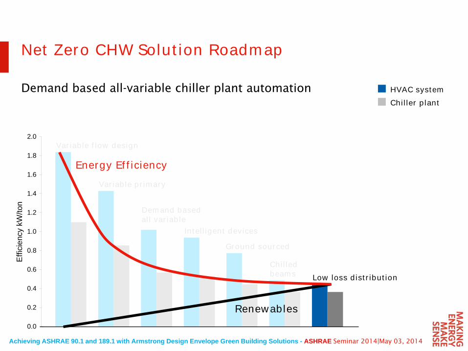
Net Zero CHW Solution Roadmap
Demand based all-variable chiller plant automation
Energy Efficiency
Renewables
Achieving ASHRAE 90.1 and 189.1 with Armstrong Design Envelope Green Building Solutions - ASHRAE Seminar 2014|May 03, 2014
0.0
0.2
0.4
0.6
0.8
1.0
1.2
1.4
1.6
1.8
2.0
Effi
cien
cy k
W/to
n
Variable flow design
Variable primary
Demand based all variable plant automation
Intelligent devices
Ground sourced
Chilled beams Low loss distribution
HVAC systemChiller plant
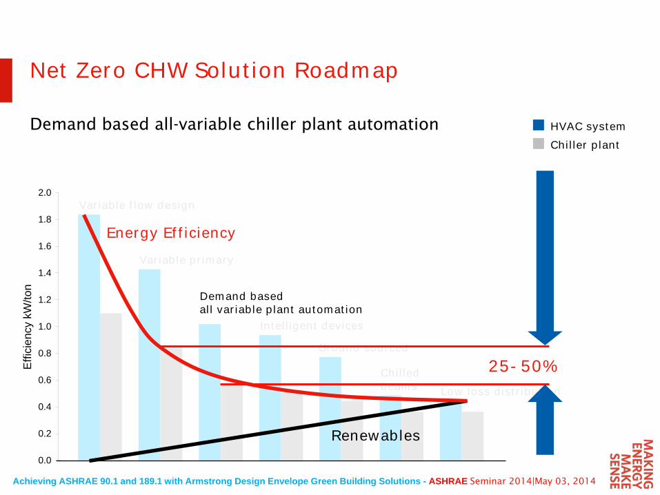
Net Zero CHW Solution Roadmap
Demand based all-variable chiller plant automation
Energy Efficiency
Renewables
25-50%
Achieving ASHRAE 90.1 and 189.1 with Armstrong Design Envelope Green Building Solutions - ASHRAE Seminar 2014|May 03, 2014
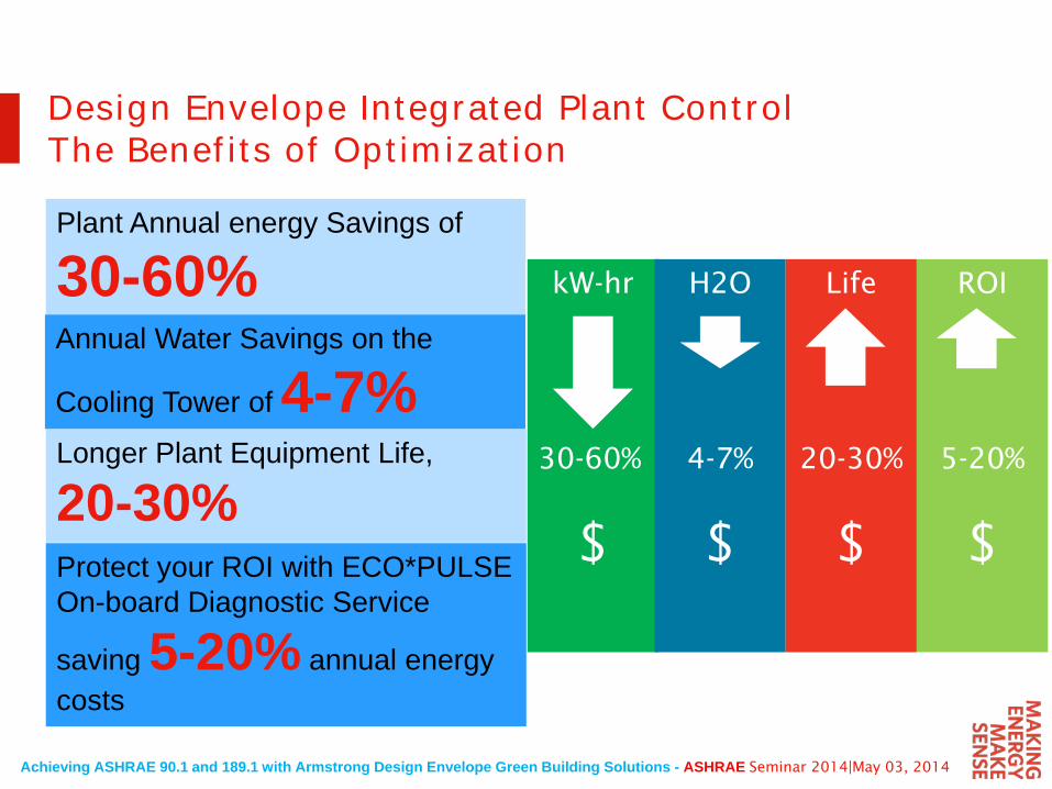
Plant Annual energy Savings of
30-60%
Design Envelope Integrated Plant ControlThe Benefits of Optimization
Annual Water Savings on the
Cooling Tower of 4-7%Longer Plant Equipment Life,
20-30%Protect your ROI with ECO*PULSE On-board Diagnostic Service
saving 5-20% annual energy costs
kW-hr
30-60%
$
H2O
4-7%
$
Life
20-30%
$
ROI
5-20%
$
Achieving ASHRAE 90.1 and 189.1 with Armstrong Design Envelope Green Building Solutions - ASHRAE Seminar 2014|May 03, 2014
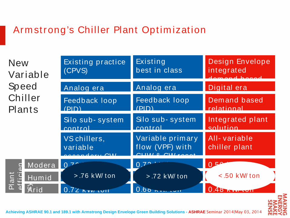
Existing practice(CPVS)
Analog eraFeedback loop (PID)Silo sub-system controlVS chillers, variable secondary CW reset0.76 kW/ton (COP 4.7)0.78 kW/ton (COP 4.6)0.72 kW/ton (COP 4.9)
Existing best in class
Analog eraFeedback loop (PID)Silo sub-system controlVariable primary flow (VPF) with CHW & CW reset0.72 kW/ton (COP 4.9)0.75 kW/ton (COP 4.7)0.68 kW/ton (COP 5.2)
Design Envelope integrated demand basedDigital eraDemand based relationalIntegrated plant solutionAll-variable chiller plant
0.50 kW/ton (COP 7.1)0.56 kW/ton (COP 6.3)0.48 kW/ton (COP 7.4)
ModerateHumidAridPl
ant
effi
cien
cy
New Variable Speed Chiller Plants
>.76 kW/ton >.72 kW/ton <.50 kW/ton
Armstrong’s Chiller Plant Optimization
Achieving ASHRAE 90.1 and 189.1 with Armstrong Design Envelope Green Building Solutions - ASHRAE Seminar 2014|May 03, 2014
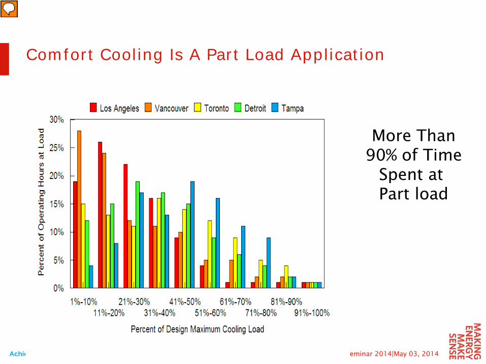
More Than90% of Time
Spent at Part load
Comfort Cooling Is A Part Load Application
Achieving ASHRAE 90.1 and 189.1 with Armstrong Design Envelope Green Building Solutions - ASHRAE Seminar 2014|May 03, 2014
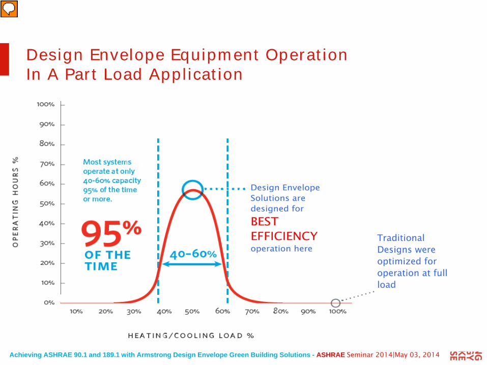
Design Envelope Equipment Operation In A Part Load Application
Design Envelope Solutions are designed for BEST EFFICIENCY operation here
Traditional Designs were optimized for operation at full load
Achieving ASHRAE 90.1 and 189.1 with Armstrong Design Envelope Green Building Solutions - ASHRAE Seminar 2014|May 03, 2014
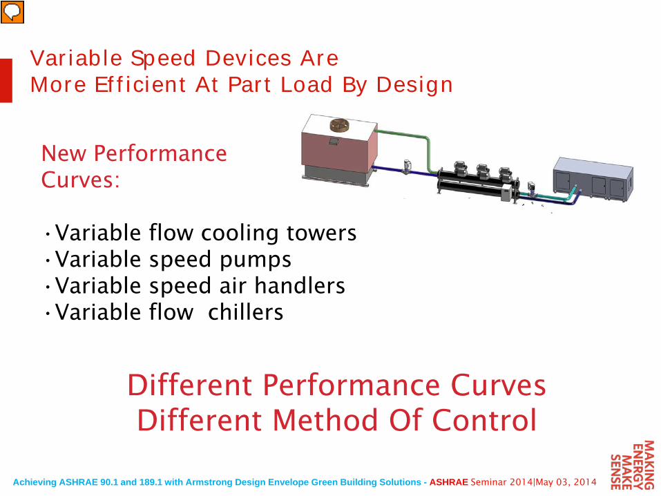
Variable Speed Devices AreMore Efficient At Part Load By Design
Different Performance CurvesDifferent Method Of Control
New PerformanceCurves:
•Variable flow cooling towers•Variable speed pumps•Variable speed air handlers •Variable flow chillers
Achieving ASHRAE 90.1 and 189.1 with Armstrong Design Envelope Green Building Solutions - ASHRAE Seminar 2014|May 03, 2014
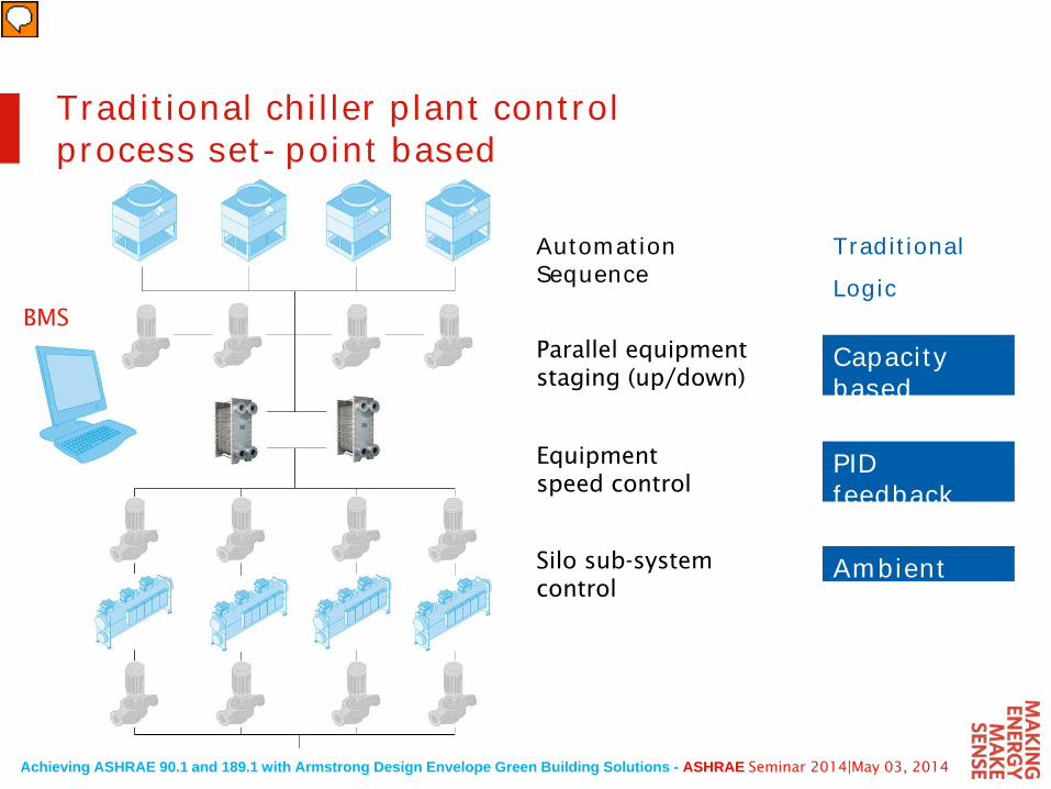
Traditional chiller plant controlprocess set-point based
BMS
Capacity basedsequencing
Automation Sequence
Parallel equipment staging (up/down)
Equipment speed control
Silo sub-system control
PID feedback control loopsAmbient reset
TraditionalLogic
Achieving ASHRAE 90.1 and 189.1 with Armstrong Design Envelope Green Building Solutions - ASHRAE Seminar 2014|May 03, 2014
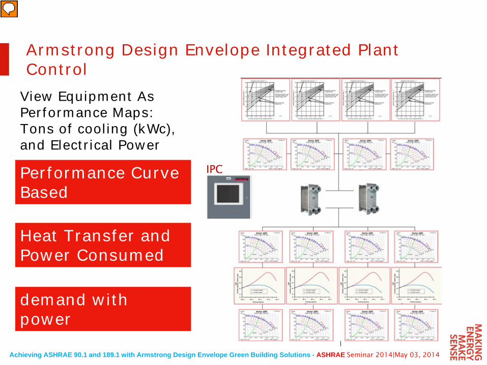
Armstrong Design Envelope Integrated Plant Control
Performance Curve Based
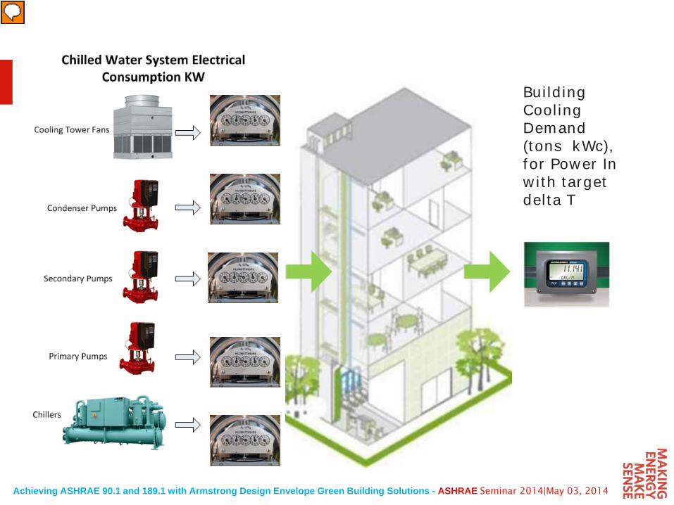
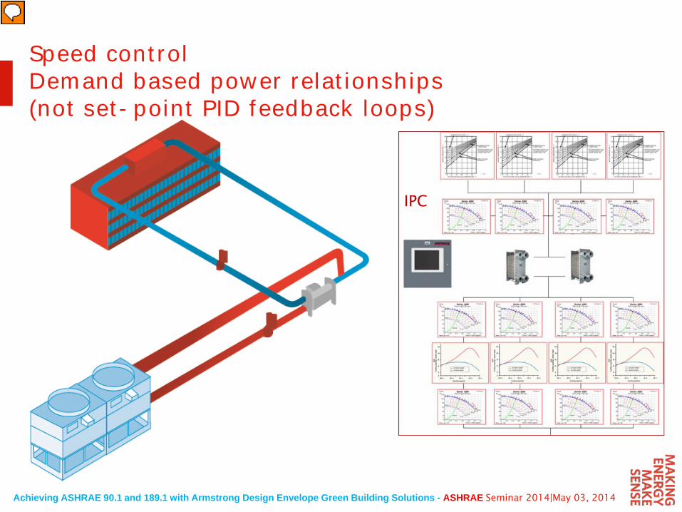
Heat Transfer and Power Consumed
demand with power relationships
View Equipment As Performance Maps: Tons of cooling (kWc), and Electrical Power
IPC
Achieving ASHRAE 90.1 and 189.1 with Armstrong Design Envelope Green Building Solutions - ASHRAE Seminar 2014|May 03, 2014
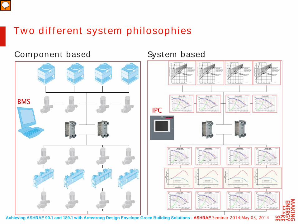
BMSIPC
Two different system philosophies
Component based System based
Achieving ASHRAE 90.1 and 189.1 with Armstrong Design Envelope Green Building Solutions - ASHRAE Seminar 2014|May 03, 2014
Building Cooling Demand (tons kWc), for Power In with target delta T
Achieving ASHRAE 90.1 and 189.1 with Armstrong Design Envelope Green Building Solutions - ASHRAE Seminar 2014|May 03, 2014
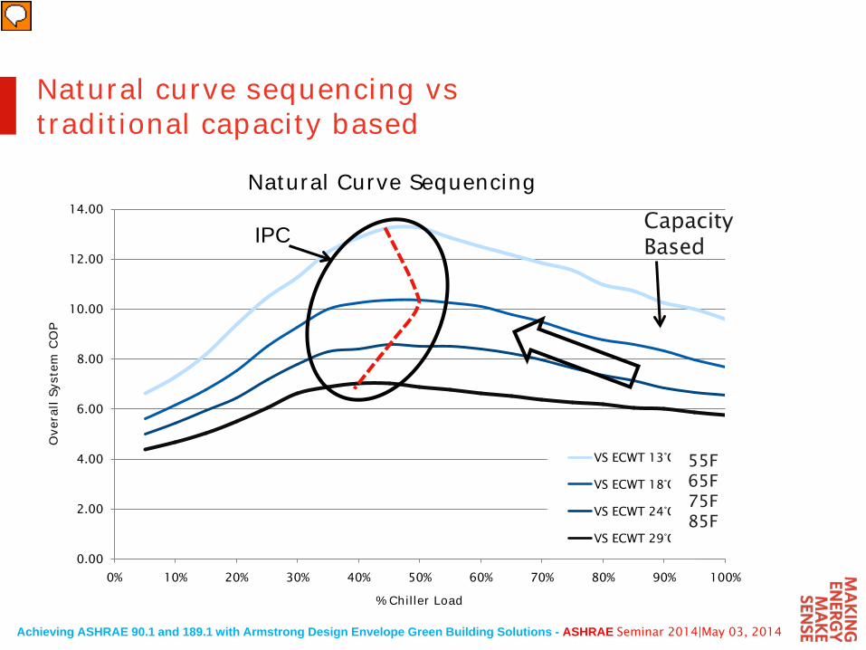
Natural curve sequencing vstraditional capacity based
0.00
2.00
4.00
6.00
8.00
10.00
12.00
14.00
0% 10% 20% 30% 40% 50% 60% 70% 80% 90% 100%
Ove
rall
Syst
em C
OP
% Chiller Load
Natural Curve Sequencing
VS ECWT 13°C
VS ECWT 18°C
VS ECWT 24°C
VS ECWT 29°C
55F65F75F85F
CapacityBasedIPC
Achieving ASHRAE 90.1 and 189.1 with Armstrong Design Envelope Green Building Solutions - ASHRAE Seminar 2014|May 03, 2014
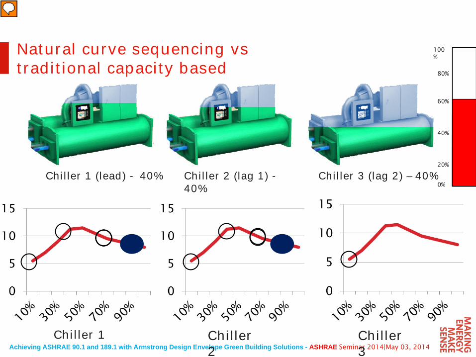
Natural curve sequencing vstraditional capacity based
Chiller 1 (lead) - 40% Chiller 2 (lag 1) -40%
Chiller 3 (lag 2) – 40%
Chiller 1 Chiller 2
Chiller 3
0%
100%
20%
40%
60%
80%
Achieving ASHRAE 90.1 and 189.1 with Armstrong Design Envelope Green Building Solutions - ASHRAE Seminar 2014|May 03, 2014
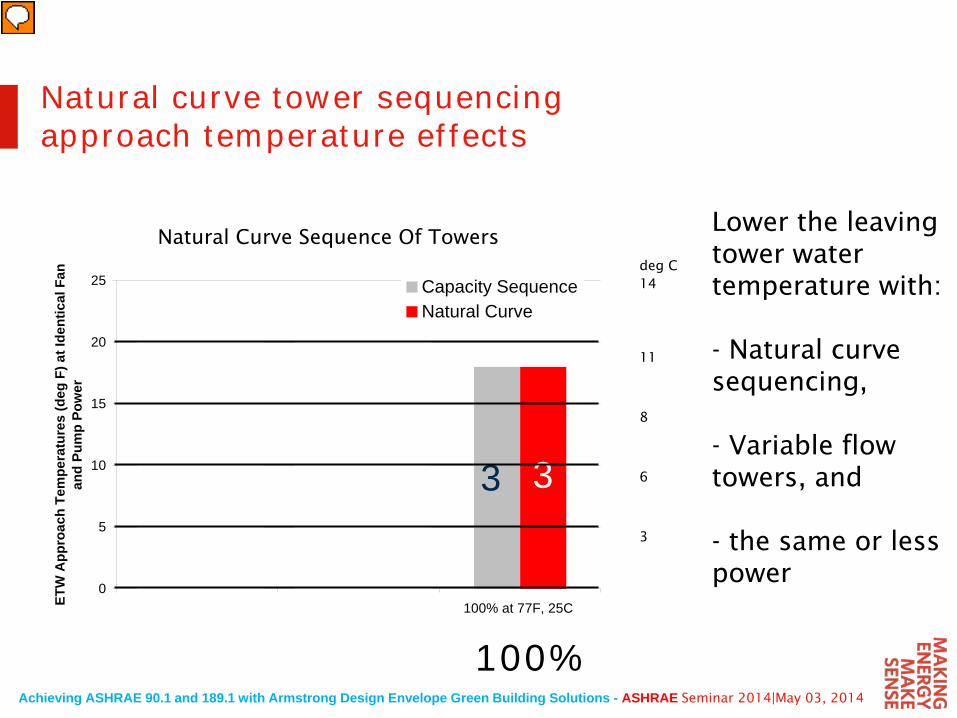
Natural curve tower sequencingapproach temperature effects
Lower the leaving tower water temperature with:
- Natural curve sequencing,
- Variable flow towers, and
- the same or less power
deg C14
11
8
6
3
Natural Curve Sequence Of Towers
0
5
10
15
20
25
33% at 56F, 13C 66% at 65F, 18C 100% at 77F, 25C ETW
App
roac
h Te
mpe
ratu
res
(deg
F) a
t Ide
ntic
al F
an
and
Pum
p Po
wer
Capacity SequenceNatural Curve
333231
33% 66% 100%
Achieving ASHRAE 90.1 and 189.1 with Armstrong Design Envelope Green Building Solutions - ASHRAE Seminar 2014|May 03, 2014
IPC
Speed controlDemand based power relationships (not set-point PID feedback loops)
Achieving ASHRAE 90.1 and 189.1 with Armstrong Design Envelope Green Building Solutions - ASHRAE Seminar 2014|May 03, 2014
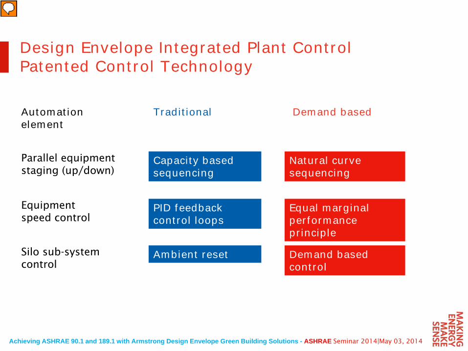
Design Envelope Integrated Plant ControlPatented Control Technology
Capacity basedsequencing
Natural curvesequencing
Automation element
Parallel equipment staging (up/down)
Equipment speed control
Silo sub-system control
PID feedback control loops
Ambient reset
Equal marginal performance principle
Demand based control
Traditional Demand based
Achieving ASHRAE 90.1 and 189.1 with Armstrong Design Envelope Green Building Solutions - ASHRAE Seminar 2014|May 03, 2014
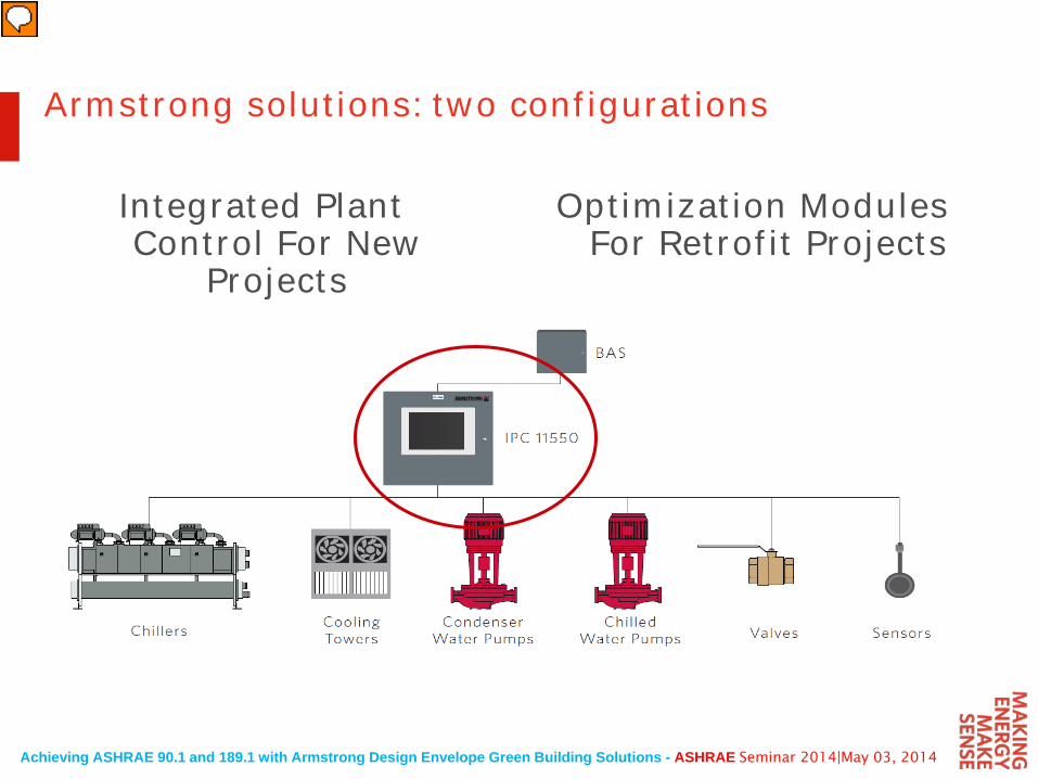
Armstrong solutions: two configurations
Integrated Plant Control For New
Projects
Optimization Modules For Retrofit Projects
Achieving ASHRAE 90.1 and 189.1 with Armstrong Design Envelope Green Building Solutions - ASHRAE Seminar 2014|May 03, 2014
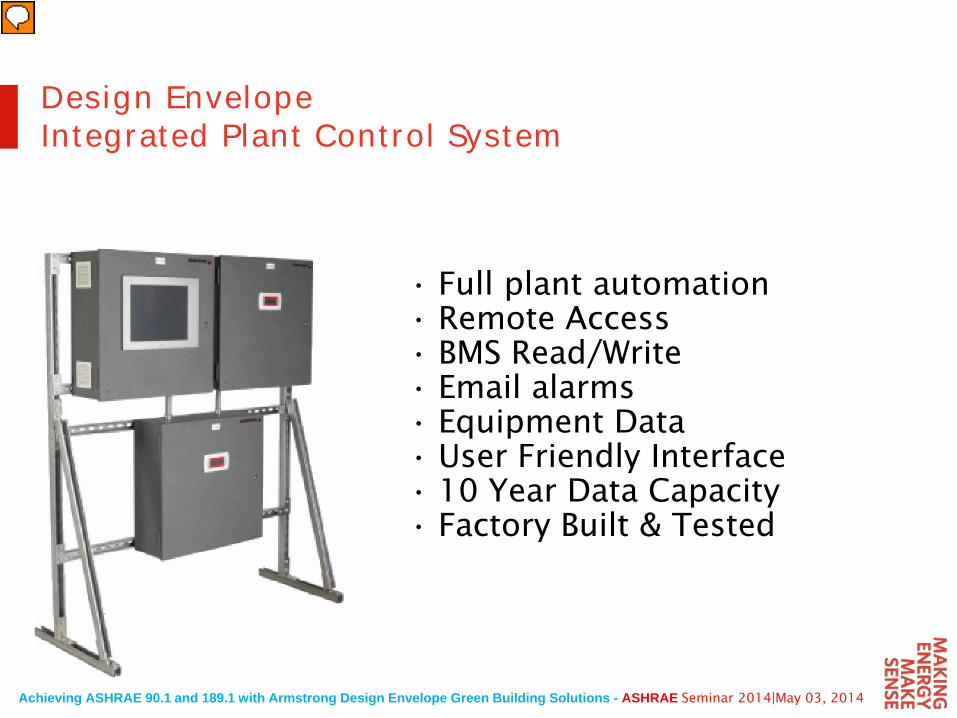
• Full plant automation• Remote Access• BMS Read/Write• Email alarms• Equipment Data• User Friendly Interface• 10 Year Data Capacity• Factory Built & Tested
Design Envelope Integrated Plant Control System
Achieving ASHRAE 90.1 and 189.1 with Armstrong Design Envelope Green Building Solutions - ASHRAE Seminar 2014|May 03, 2014
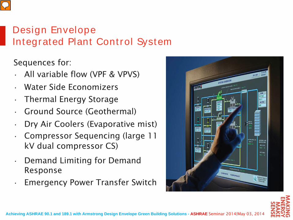
Sequences for:
Design Envelope Integrated Plant Control System
• Emergency Power Transfer Switch
• All variable flow (VPF & VPVS)
• Water Side Economizers
• Thermal Energy Storage
• Ground Source (Geothermal)
• Dry Air Coolers (Evaporative mist)
• Compressor Sequencing (large 11 kV dual compressor CS)
• Demand Limiting for Demand Response
Achieving ASHRAE 90.1 and 189.1 with Armstrong Design Envelope Green Building Solutions - ASHRAE Seminar 2014|May 03, 2014
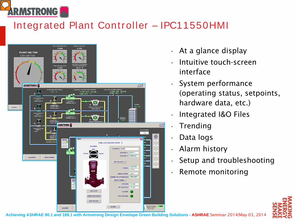
• At a glance display
• Intuitive touch-screen interface
• System performance (operating status, setpoints, hardware data, etc.)
• Integrated I&O Files
• Trending
• Data logs
• Alarm history
• Setup and troubleshooting
• Remote monitoring
0.55 kW/TON
Integrated Plant Controller – IPC11550HMI
Achieving ASHRAE 90.1 and 189.1 with Armstrong Design Envelope Green Building Solutions - ASHRAE Seminar 2014|May 03, 2014
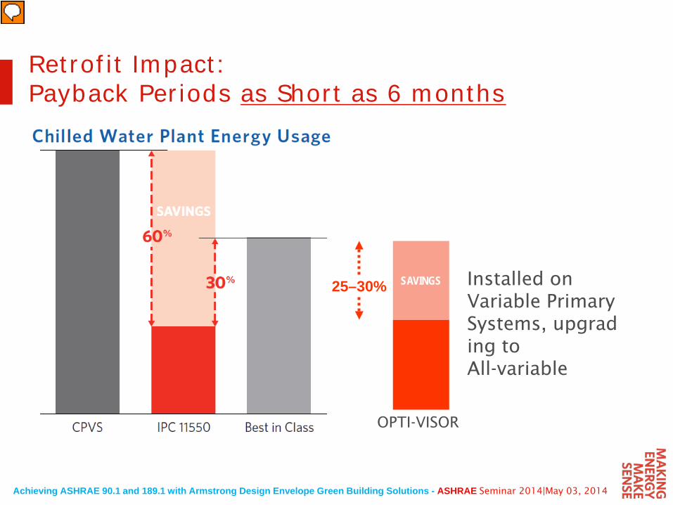
Retrofit Impact: Payback Periods as Short as 6 months
SAVINGS25–30%
OPTI-VISOR
Installed on Variable Primary Systems, upgrading to All-variable
Achieving ASHRAE 90.1 and 189.1 with Armstrong Design Envelope Green Building Solutions - ASHRAE Seminar 2014|May 03, 2014
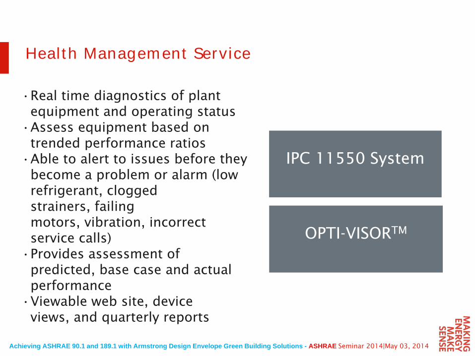
Health Management Service
•Real time diagnostics of plant equipment and operating status
•Assess equipment based on trended performance ratios
•Able to alert to issues before they become a problem or alarm (low refrigerant, clogged strainers, failing motors, vibration, incorrect service calls)
•Provides assessment of predicted, base case and actual performance
•Viewable web site, device views, and quarterly reports
IPC 11550 System
OPTI-VISORTM
Achieving ASHRAE 90.1 and 189.1 with Armstrong Design Envelope Green Building Solutions - ASHRAE Seminar 2014|May 03, 2014
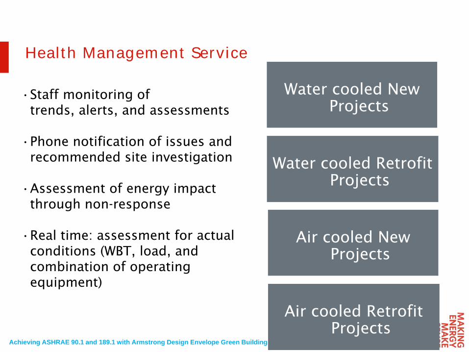
Health Management Service
•Staff monitoring of trends, alerts, and assessments
•Phone notification of issues and recommended site investigation
•Assessment of energy impact through non-response
•Real time: assessment for actual conditions (WBT, load, and combination of operating equipment)
Water cooled New Projects
Water cooled Retrofit Projects
Air cooled New Projects
Air cooled Retrofit Projects
Achieving ASHRAE 90.1 and 189.1 with Armstrong Design Envelope Green Building Solutions - ASHRAE Seminar 2014|May 03, 2014
0.0
0.2
0.4
0.6
0.8
1.0
1.2
1.4
1.6
1.8
2.0
Effi
cien
cy k
W/to
n
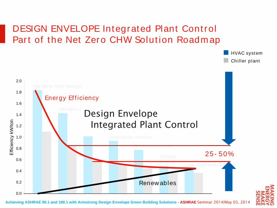
Variable flow design
Variable primary
Demand based all variable plant automation
Intelligent devices
Ground sourced
Chilled beams Low loss distribution
HVAC systemChiller plant
DESIGN ENVELOPE Integrated Plant ControlPart of the Net Zero CHW Solution Roadmap
Design Envelope Integrated Plant Control
Energy Efficiency
Renewables
25-50%
Achieving ASHRAE 90.1 and 189.1 with Armstrong Design Envelope Green Building Solutions - ASHRAE Seminar 2014|May 03, 2014
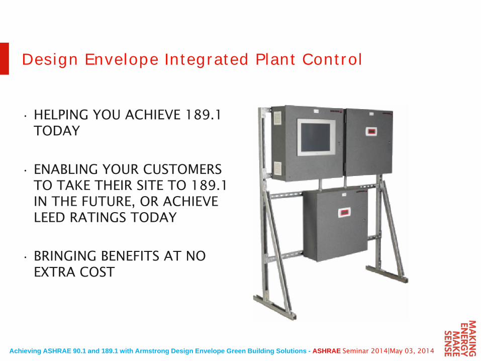
• HELPING YOU ACHIEVE 189.1 TODAY
• ENABLING YOUR CUSTOMERS TO TAKE THEIR SITE TO 189.1 IN THE FUTURE, OR ACHIEVE LEED RATINGS TODAY
• BRINGING BENEFITS AT NO EXTRA COST
Design Envelope Integrated Plant Control
Achieving ASHRAE 90.1 and 189.1 with Armstrong Design Envelope Green Building Solutions - ASHRAE Seminar 2014|May 03, 2014
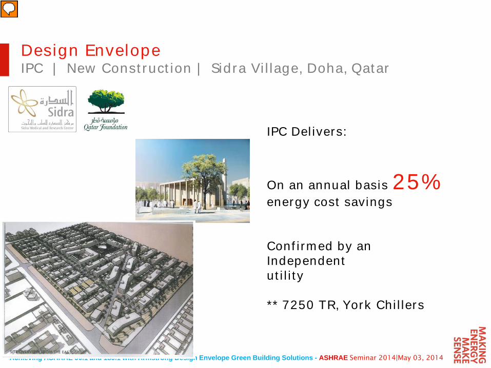
Design EnvelopeIPC | New Construction | Sidra Village, Doha, Qatar
IPC Delivers:
On an annual basis 25%energy cost savings
Confirmed by an Independentutility
** 7250 TR, York Chillers
Achieving ASHRAE 90.1 and 189.1 with Armstrong Design Envelope Green Building Solutions - ASHRAE Seminar 2014|May 03, 2014
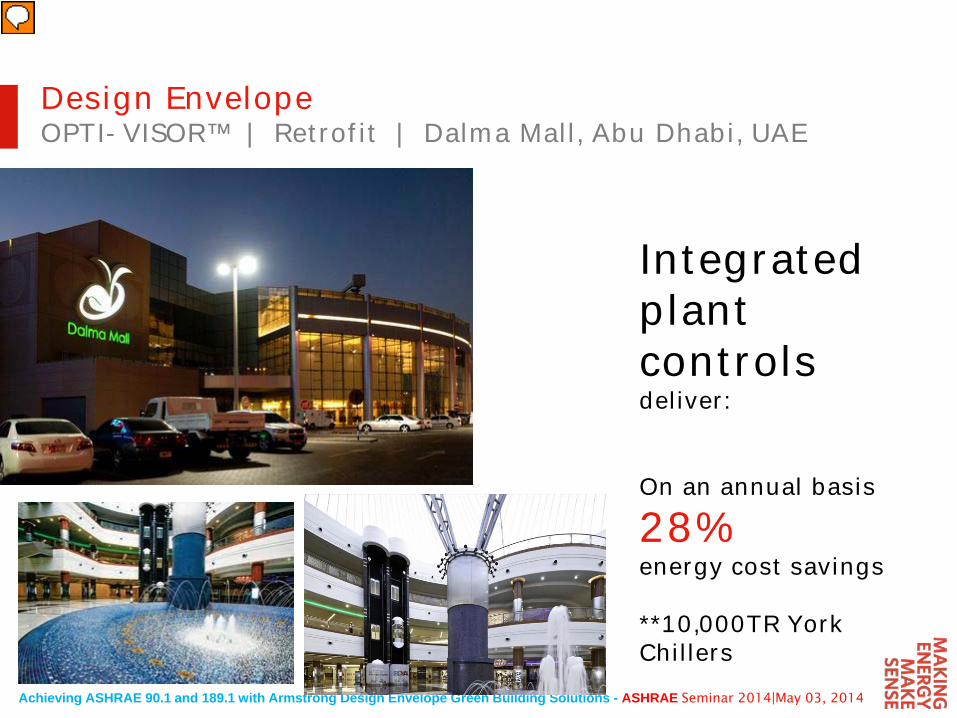
Integrated plant controls deliver:
On an annual basis
28%energy cost savings
**10,000TR York Chillers
Design EnvelopeOPTI-VISOR™ | Retrofit | Dalma Mall, Abu Dhabi, UAE
Achieving ASHRAE 90.1 and 189.1 with Armstrong Design Envelope Green Building Solutions - ASHRAE Seminar 2014|May 03, 2014
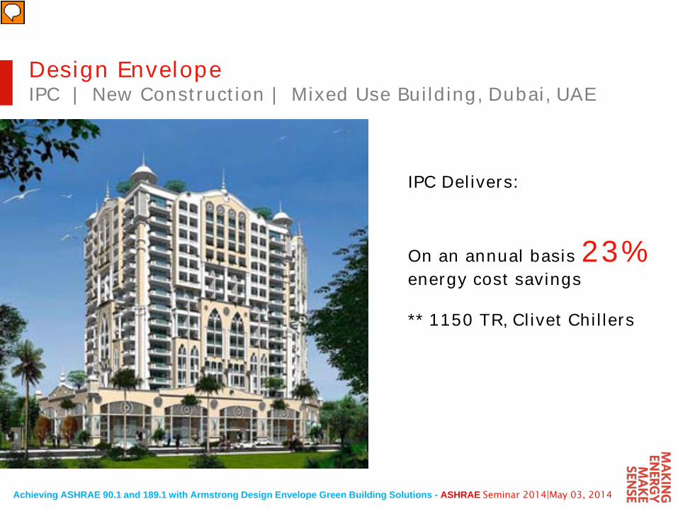
Design EnvelopeIPC | New Construction | Mixed Use Building, Dubai, UAE
IPC Delivers:
On an annual basis 23%energy cost savings
** 1150 TR, Clivet Chillers
Achieving ASHRAE 90.1 and 189.1 with Armstrong Design Envelope Green Building Solutions - ASHRAE Seminar 2014|May 03, 2014
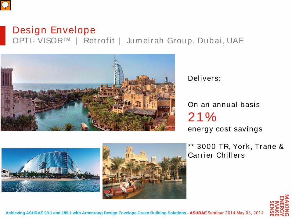
Design EnvelopeOPTI-VISOR™ | Retrofit | Jumeirah Group, Dubai, UAE
Delivers:
On an annual basis
21%energy cost savings
** 3000 TR, York, Trane & Carrier Chillers
Achieving ASHRAE 90.1 and 189.1 with Armstrong Design Envelope Green Building Solutions - ASHRAE Seminar 2014|May 03, 2014
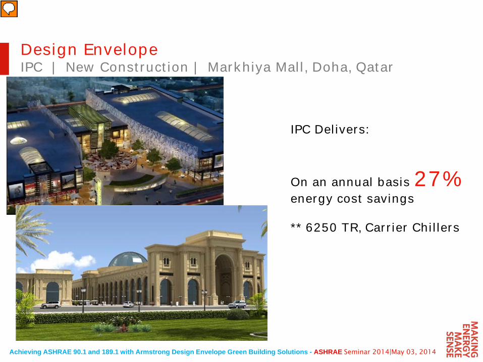
Design EnvelopeIPC | New Construction | Markhiya Mall, Doha, Qatar
IPC Delivers:
On an annual basis 27%energy cost savings
** 6250 TR, Carrier Chillers
Achieving ASHRAE 90.1 and 189.1 with Armstrong Design Envelope Green Building Solutions - ASHRAE Seminar 2014|May 03, 2014
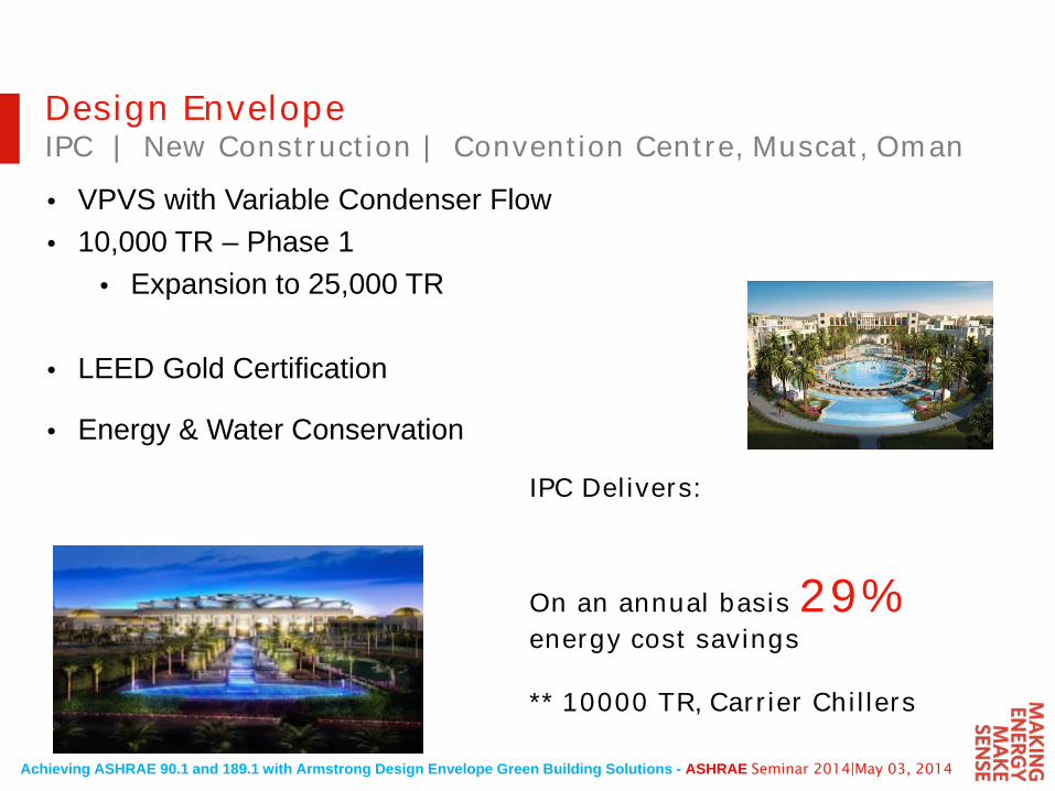
• VPVS with Variable Condenser Flow• 10,000 TR – Phase 1
• Expansion to 25,000 TR
• LEED Gold Certification
• Energy & Water Conservation
Design EnvelopeIPC | New Construction | Convention Centre, Muscat, Oman
IPC Delivers:
On an annual basis 29%energy cost savings
** 10000 TR, Carrier Chillers

Achieving ASHRAE 90.1 and 189.1 with Armstrong Design Envelope Green Building Solutions - ASHRAE Seminar 2014|May 03, 2014
Armstrong Fluid Technology
Thank You For Your Attention
Questions?